1
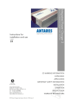
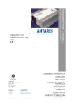
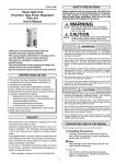
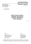
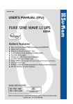
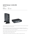
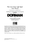
1. Safety and Overview In case of fire around UPS, put out the fire with powder fire extinguishers. Using fluid extinguisher may lead to electric shock. Safety precautions (In order to ensure the safety, please observe the following) Please be sure to read the user’s manual before use. Please charge the product for more than 8 hours before using it. When the battery has been discharged or the storage period has been more than 3 socket in emergency. electric shock. When installing the product, please maintain a distance of more than 50cm away The battery maintenance shall only be carried out by the personnel having professional knowledge of batteries. supporting system and other specific major equipments. The battery life is shortened as the ambient temperature rises. Periodic battery replacement can ensure UPS works properly and there is enough backup time. This product is specially designed for group computers. It shall not be connected with inductive loads (e.g. motor, refrigerator, etc.). It is not recommended for life When it is required to move or re-connect UPS, the AC input power shall be cut off to ensure UPS stops completely, or the output end may be live which may result in months, the battery shall be charged for more than 8 hours in time, so as to ensure it is fully-charged and prevent it from being damaged. Please place the power socket near UPS, so that UPS can be disconnected from the Since the dangers of electric shock and short-circuit current exist, the following from the display. warnings shall be observed in battery replacement to avoid electric shock. The normal temperature of the chassis surface will reach about 50℃ during the use 1) Do not wear watches, rings or other metal objects. of this product, which is a normal phenomenon. 2) Use insulated tools. Do not use UPS which goes beyond the rated load capacity. 3) Wear rubber shoes and glove. Do not open UPS case, or it will lead to electric shock or other dangers. If it is 4) Do not place metal tools or metal parts on the battery. required to conduct an internal overhaul or replace the battery, please deliver it to the 5) First disconnect the load connected to the battery before removing connecting terminals of the battery. designated maintenance center. As internal short-circuit will result in electric shock or fire, any vessel containing 6) shock or fire. liquids shall not be placed on UPS for fear of electric shock or other dangers. When the machine works abnormally, cut off the power immediately, and contact the Do not short-circuit the positive and negative terminals, or it will lead to electric 7) Do not touch the connecting terminal of the battery. Do not separate the battery supplier. circuit from the input voltage circuit. The danger of high voltage exists between Never store or use this product in the following conditions. the battery terminal and ground. 1) 2) The place where there is no air convection The place where combustible gas, corrosive substance or a great deal of dust exists 3) The place where the temperature is extremely high or low (above 40℃ or below 0℃) and the humidity is high (above 90%) 4) 5) 6) The place having direct sun exposure or close to heating equipment The place where violent vibration occurs Outdoor -2- Warning! The equipment must be grounded. When AC utility power is connected, the system shall be grounded reliably. Improper operation will result in huge losses. Please be sure to operate this product according to the requirements of operation instructions. -3- 2 Installation Instructions 25% 25% ON 50% 75% 75% O UT PU T VA C HZ LI 100% OFF 100% ROTA TE /S ET TE S T/MUT E 50% 2.1 Unpacking and checking NE 2.1.1 Unpack UPS, and check accessories Host Instructions Warranty card Communication line Power cord CD Battery connecting wire (not provided for standard UPS) Accessories of fixed support (not provided for tower UPS) Rack (wall-mounted) accessories (not provided for tower UPS) Fig. 2.2 Rack panel 2.3 UPS rear panel view 2.3.1 Tower rear panel Others according to requirements of the contract Note: Please keep the carton and packaging materials of the machine for convenience of future handling. The series of products are very heavy which shall be handled with care. 2.1.2 Check whether UPS is damaged during the transportation. If any damage or missing parts are found, do not start up the machine, and inform the carrier and distributor Fig. 2.3.1 1KVA-2KVA rear panel (left), 3KVA rear panel (right) 2.2 UPS front panel view 2.3.2 Rack rear panel TEST/MUTE ON OFF Fig. 2.2 Tower panel Fig. 2.3.2 2U 1KVA rack rear panel -4- -5- 5. It is recommended to charge the battery for 8 hours before using it. UPS will charge the battery automatically as long as the input utility power meeting requirements is connected to the host. 6. For the extended runtime model, connect the battery first after confirming the battery wires, and then connect the utility power line. 15cm TEST /MUTE ON OF F 15cm Fig. 2.3.2 3U 1.5KVA-3KVA rack rear panel Description of rear panel a) Fan and fan guard Fig. 2.4.1 Installation attentions b) Output power supply socket 2.4.2 Battery installation attentions for extended runtime model c) AC over-current protector d) IEC Input socket Warning: e) Communication interface (standard configuration USB+RJ45) In order to ensure the safety of equipment and personnel, theinstallation must be f) carried out by professionals. SNMP card slot 1. First connect the battery bank with accompanied battery connecting wires (note g) External battery connector the red wire shall be connected to the anode, and the black wire shall be 2.4 Product installation instructions connected to the cathode). 2. Confirm the connection of the battery bank. Measure the identification of the 2.4.1 Installation attentions 1. Put UPS in a well-ventilated place and ensure the heat emission holes and fan battery input socket and the positive and negative of battery wire terminals of peripherals of the chassis meet the ventilation conditions at a distance of UPS with a multimeter. The voltage shall be consistent with UPS’s input DC 150mm above and keep away from water, combustible gases and corrosives. voltage. 2. Turn off the devices which need uninterrupted power supply (such as host 3. Be sure to check whether the installation is correct or not after it is completed. computer), disconnect the power cord from the utility power socket and connect it to the output socket of UPS connect the devices which do not need to be connected with UPS to the common utility power socket. 3. Put UPS input plug into the utility power socket (ensure the zero wire and live wire are correct and the ground wire is good). 4. The ambient temperature of UPS shall be kept between 0℃ and 40℃. Fig. 2.4.2 Schematic diagram of DC24V tower battery connection -6- -7- Vertical installation Combine the connecting extensions and RT foot pieces among the accessories into two racks according to the following figure. Align the racks at a proper distance and place them on the plane in parallel. Connecting extension RT foot piece Fig. 2.4.2 Schematic diagram of DC48V tower battery connection Placed in parallel Fig. 2.4.3 Assembly diagram of foot pieces Keep the machine upright and put it on two racks. Do not turn upside down. Fig. 2.4.2 Schematic diagram of DC24V rack battery connection Fig. 2.4.2 Schematic diagram of DC48V rack battery connection Fig. 2.4.3 Vertically positioned UPS 2.4.3 Installation 1. This product shall be installed by professionals. The provided power cord can be B connected to the wall socket to serve as UPS input power. 2. Before the use of UPS, the battery shall be charged for more than 8 hours. Rack installation Fasten the rack parts among the accessories to both sides of the chassis with screws (as shown below). UPS will charge the battery automatically as long as it is connected to the utility power line. 3. Installation of rack UPS. -8- -9- 3. Function Setting of Panel Keys and Description of LCD Display 3.1 Description of panel keys Screws Rack foot pieces Fig. 2.4.3 Installation of rack parts When the rack parts have been installed, fasten UPS to the rack (as shown below). Description of rack panel keys Key combination Description of tower panel keys Function introduction Press the two keys for 3 seconds to start up. Fig. 2.4.3 Rack installation 1) 2) Press the two keys for 3 seconds to shut down. Press the setting interface for 5 seconds to restore factory settings and exit the setting interface. 1) 2) Press “ ” momentarily to enable inverter mute. In the utility power mode, press “ ” momentarily to enable the battery discharge testing for 15 seconds. Press the key for 5 seconds to enter the setting interface. Press the key momentarily in the setting interface to turn the page. Press the key for 3 seconds to exit the setting interface without saving data. Select the item to be set in the setting interface. After selecting the required setting, page down to “save and exit” 1) 2) 3) 4) 5) 6) -10- page. Choose “Yes”, press “ ” momentarily to save the date and exit the setting mode. In non-setting mode, momentarily press the key twice, and the LCD display content rotates. In setting mode, when it goes to SAVE page, press “ ” or “ ” momentarily, choose “Yes”, press “ ” to complete the setting and exit the mode. -11- 1) 2) 1) 2) 3) In non-setting mode, press the key momentarily to turn the page (page up). In setting mode, the parameter decreasing iterates. In non-setting mode, press the key momentarily to turn the page (page down). In setting mode, the parameter decreasing iterates. In non-setting mode, press the key for 2 seconds to enter the state of automatic page up/down and re-press the key for 2 seconds to exit the state of automatic page up/down. 3.2 Functions of LED indicators 3.3 LCD display functions Graphic display Battery Load Numerical and functional setting Working mode Rack LCD Graphic display Load display Battery capacity Numerical setting display They are respectively output indicator, inverter indicator, bypass indicator and alarm indicator from left to right. 1. The green indicator of UPS is normally on referring to that UPS works in the utility mode or inverter mode. Working mode Functional setting display Tower LCD Graphics, load and battery capacity display area 2. The red inverter indicator is normally on referring to that UPS works in the inverter mode. 1. Each grid of the load and battery capacity display area 25% capacity. The overload icon will flash in case of UPS overload. 3. The yellow bypass indicator is normally on referring to that UPS works in the bypass mode or setting mode. 2. The fan icon displays the working state of the fan. When the fan works, the fan icon is in a rotating state and when the fan stops, the fan icon is normally on. 4. The red alarm indicator lamp flashes referring to UPS failure (battery failure, utility power failure). 3. In case of utility power failure, the failure icon flashes in case of battery failure, the failure icon is normally on. 4. Numerical and functional setting display area. 5. In non-setting mode, the output information displays normally by pressing “Page UP” or “Page Down” key, the input, battery, load and temperature information can be seen. 6. In the setting mode of rack UPS, by pressing functional setting key and “Page UP” or “Page Down” key, the input voltage value, frequency, low voltage shutdown time, charging current and inverter no-load shutdown function can be set. -12- -13- 7. In the setting mode of tower UPS, by pressing functional setting key and “Page Note UP” or “Page Down” key, the output voltage value, frequency, low voltage 1. Before UPS start-up operation, first start UPS and then add the computer and shutdown time, charging current, inverter no-load shutdown function, inverter other loads when shut down, first shut down the computer and other loads no-load power saving mode, DC self-starting function and AC self-starting and then UPS. function can be set. 2. Once the utility power is interrupted, UPS will be powered by the battery. Working mode display area Please conduct save actions or other emergency processing for PC and other The display area mainly displays the working mode, such as STDBY (standby loads in time. mode – rack LCD display), LINE (utility mode), BATT (battery mode), BYPASS 3. If UPS will not be used for more than 7 days, please shut down it according to (bypass mode – tower LCD display). the steps of UPS “shutdown with utility power”. 4. If UPS has not been used for more than 3 months, please refer to the method 4. of UPS startup with utility power, charge UPS for more than 12 hours to keep Startup and Shutdown Operations the battery fully charged and extend battery life. 4.1 Startup operation Startup with utility power After connected with utility power, UPS will start up and beginning self-test (bypass 5. Panel Setting Operation output) automatically and enter normal working state in 15 seconds. As UPS working 5.1 Output voltage setting indicator (green light) goes on and bypass indicator goes off, the user can start PC and other loads. Startup with battery When powered by the battery (without utility power) Press the front panel startup combination button for 3 seconds. UPS will start the inverter, and the power supply output will function normally at this moment, UPS working indicator (green light) lighting, inverter indicator lighting and failure indicator flashes. 1. The left figure shows the output voltage setting interface of rack UPS, and the right figure shows the output voltage setting interface of tower UPS. 4.2 Shutdown operation Shutdown with utility power Press the front panel shutdown combination button for 3 seconds. UPS will enter standby mode (rack) or bypass mode (tower). The yellow bypass indicator goes on. Then cut off the utility power supply to shut down UPS. Shutdown with battery 2. Press the function setting key “ ” for more than 5 seconds to enter the setting interface. Press the key “ ” momentarily to select the output voltage setting interface. Press the key “ ” momentarily to select the voltage. Available voltage values are 220V, 230V and 240V the output voltage is 220V by default. Press the front panel shutdown combination button for 3 seconds to shut down UPS. -14- ” or “ -15- 3. After selecting “Confirm”, press the key “ ” momentarily to save the interface (by reference to “save and exit setting”). Press the key “ momentarily, choose “Yes”, and then press the key “ ” or “ ” ” momentarily to save 1. The left figure shows the boost charge voltage interface of rack UPS, and the right figure shows the boost charge voltage interface of tower UPS. 2. Press the function setting key “ setting interface. Press the key “ and exit it. ” for more than 5 seconds to enter the ” momentarily to select the equalizing charge voltage interface. The equalizing charge voltage cannot be set 5.2 Frequency setting through the panel. It is 14.4V by default. 5.4 Floating charge voltage 1. The left figure shows the frequency setting interface of rack UPS, and the right figure shows the frequency setting interface of tower UPS. 2. Press the function setting key “ ” for more than 5 seconds to enter the setting interface. Press the key “ ” momentarily to select the output voltage standard setting interface. Press the key “ ” or “ ” momentarily to select 1. The left figure shows the floating charge voltage interface of rack UPS, and the right figure shows the floating charge voltage interface of tower UPS. 2. Press the function setting key “ ” for more than 5 seconds to enter the the frequency. Available frequency values are 50Hz and 60Hz the frequency is setting interface. Press the key “ 50Hz by default. charge voltage interface. The floating charge voltage cannot be set through the 3. After selecting “Confirm”, press the key “ ” momentarily to save the interface (by reference to “save and exit setting”). Press the key “ momentarily, choose “Yes”, and then press the key “ ” or “ ” ” momentarily to select the equalizing panel. It is 13.7V by default. 5.5 Battery end of discharge voltage setting ” momentarily to save and exit it. 5.3 Boost charge voltage 1. The left figure shows the battery end of discharge voltage setting interface of rack UPS, and the right figure shows the battery end of discharge voltage setting interface of tower UPS. -16- -17- 2. Press the function setting key “ ” for more than 5 seconds to enter the setting interface. Press the key “ ” momentarily to select the battery end of discharge voltage setting interface. Press the key “ ” or “ 5.7 Inverter no-load shutdown function setting ” momentarily to select the battery end of discharge voltage. Available voltage values are 9.6V-11.5V the end of discharge voltage is 10.2V by default. 3. After selecting “Confirm”, press the key “ ” momentarily to save the interface (by reference to “save and exit setting”). Press the key “ momentarily, choose “Yes”, and then press the key “ ” or “ ” ” momentarily to save 1. The left figure shows the inverter no-load shutdown function setting interface of rack UPS, and the right figure shows the inverter no-load shutdown function and exit it. setting interface of tower UPS. 5.6 Charging current setting 2. Press the function setting key “ setting interface. Press the key “ ” for more than 5 seconds to enter the ” momentarily to select inverter no-load shutdown function setting interface. Press the key “ ” or “ ” momentarily to select the inverter no-load shutdown function. The user can select ON or OFF the inverter no-load shutdown function is off by default. 3. After selecting “Confirm”, press the key “ 1. The left figure shows the charging current setting interface of rack UPS, and the right figure shows the charging current setting interface of tower UPS. ” for more than 5 seconds to enter the setting interface. Press the key “ ” momentarily to select charging current ” or “ interface (by reference to “save and exit setting”). Press the key “ momentarily, choose “Yes”, and then press the key “ 2. Press the function setting key “ setting interface. Press the key “ ” momentarily to save the ” or “ ” ” momentarily to save and exit it. 5.8 Inverter no-load power saving function setting ” momentarily to select the charging current. Available current values are 0A, 1A, 2A for standard model, and 0A-10A, 15A, 20A for extended runtime model the charging current is 1A for standard model and 10A for extended runtime model by default. 3. After selecting “Confirm”, press the key “ ” momentarily to save the interface (by reference to “save and exit setting”). Press the key “ momentarily, choose “Yes”, and then press the key “ ” or “ ” ” momentarily to save 1. The above figure shows the inverter no-load power saving function setting interface of tower UPS (tower UPS can be set through the panel). and exit it. -18- -19- 2. Press the function setting key “ setting interface. Press the key “ ” for more than 5 seconds to enter the 5.10 AC self-start function setting ” momentarily to select inverter no-load power saving function setting interface. Press the key “ ” or “ ” momentarily to select the inverter no-load power saving function. The user can select ON or OFF the inverter no-load power saving function is off by default. 3. After selecting “Confirm”, press the key “ ” momentarily to save the interface (by reference to “save and exit setting”). Press the key “ momentarily, choose “Yes”, and then press the key “ ” or “ ” ” momentarily to save and exit it. 1. The above figure shows AC function setting interface of tower UPS (tower UPS can be set through the panel). 2. Press the function setting key “ 5.9 DC self-start function setting setting interface. Press the key “ ” for more than 5 seconds to enter the ” momentarily to select DC Auto-start function setting interface. Press the key “ ” or “ ” momentarily to select the AC auto-start function. The user can select “ON” or “OFF” the AC Auto-start function is off by default. 3. After selecting “Confirm”, press the key “ ” momentarily to save the interface (by reference to “save and exit setting”). Press the key “ 1. The above figure shows DC function setting interface of tower UPS (tower momentarily, choose “Yes”, and then press the key “ ” or “ ” ” momentarily to save and exit it. UPS can be set through the panel). 2. Press the function setting key “ ” for more than 5 seconds to enter the setting interface. Press the key “ ” momentarily to select DC self-starting function setting interface. Press the key “ ” or “ ” momentarily to select the DC self-starting function. The user can select ON or OFF 5.11 Save and exit setting or direct-exit setting Save and exit setting the DC self-starting function is off by default. 3. After selecting “Confirm”, press the key “ ” momentarily to save the interface (by reference to “save and exit setting”). Press the key “ momentarily, choose “Yes”, and then press the key “ ” or “ ” ” momentarily to save and exit it. 1. The left figure shows “save setting” interface of rack UPS, and the right figure shows the inverter no-load shutdown function setting interface of tower UPS. -20- -21- 2. In setting mode, after confirming the selected parameters, press the key “ momentarily to save the interface. Press the key “ choose “Yes”, and then press the key “ ” or “ ” ” momentarily, ” momentarily to save and exit it. Direct-exit setting 1. Press the key combination “ ” for 5 seconds in the setting interface to restore factory settings of UPS, and then exit the setting interface. 3. Temperature Display the temperature inside the chassis, as shown below (the 2. Press the key “ ” for 3 seconds to exit the setting interface of UPS without saving the data. 6. left figure shows the display interface of rack UPS, and the right figure shows the display interface of tower UPS). Parameter Query Operation Press the query key “ ” or “ ” momentarily to check output, load, temperature, input and battery information in turn. In non-setting mode, press the key “ ” for 2 seconds to enter the state of automatic page up/down and re-press the key for 2 seconds to exit the state of automatic page up/down. 4. Input Display the input voltage and input frequency, as shown below (the left 1. Output Display UPS output voltage and output frequency, as shown below (the left figure shows the display interface of rack UPS, and the right figure shows figure shows the display interface of rack UPS, and the right figure shows the display interface of tower UPS). the display interface of tower UPS). 2. Load Display WATT and VA values of the connected load, depending on load 5. Battery Display the battery voltage and battery capacity, as shown below. type and load value, as shown below (the left figure shows the display interface of rack UPS, and the right figure shows the display interface of tower UPS). -22- -23- Output frequency 50Hz/60Hz±0.3Hz (settable) Waveform Power 7. Technical Specifications Note “S” refers to tower standard model. “H” refers to tower extended runtime model RTS refers to rack RT convertible standard model. RTH refers to rack RT convertible extended runtime model. Model 1000VA (S/H/RT) 1500VA (S/RT) 2000VA (S/H/RT) 3000VA (S/H/RT) 24V 36V (H 48V) 48V 20-30V 30-45V (H 40-60V) 40-60V DC input Rated voltage DC input range (default) AC input range (utility mode) Frequency input range Generator connection 0-300Vac for 220Vac/230Vac/240Vac, 0-150Vac for 100Vac/110Vac/120Vac 165-280Vac for 220Vac, 175-290Vac for 230Vac, 185-300Vac for 240Vac 70-130Vac for 100Vac, 80-140Vac for 110Vac, 90-150Vac for 120Vac 50Hz/60Hz (automatic detection), 45-55Hz for 50Hz, 55-65Hz for 60Hz Yes Output Inverter output range AC output range (bypass mode) AC output range (utility mode) 220Vac/230Vac/240Vac±5% (settable) 100Vac/110Vac/120Vac±5% (settable) 0-300Vac for 220Vac/230Vac/240Vac, 0-150Vac for 100V/110V/120V 188-245Vac for 220Vac, 199-254Vac for 230Vac, 210-264Vac for 240Vac 90-110Vac for 100Vac, 99-121Vac for 110Vac, 108-132Vac for 120Vac -24- Battery capacity (H external expansion) Charging mode 1000VA 1500VA 2000VA 3000VA 0.8 Max 85% It can be set (<3% load) to enter the mode after 80s It can be set (<3% load) to shut down after 80s ≤10ms <5% Yes Yes Yes Overload, short circuit, battery low voltage, battery overcharge 105% 300s, 110% 120s, 125% 60s, 150% 10s (enter bypass mode later) 105% 300s, 110% 60s, 125% 10s, 150% 0.7s (shut down later) Auto mute after 60s or manual mute 12V/7AH*2 (H 12V*2) 12V/9AH*3 (H 12V*4) 2 Stage-Bulk, Float 12V/9AH*2 12V/9AH*4 (H 12V*4) Standard model 1A (default), 0-2A adjustable, Step 1A AC input AC input range (bypass mode) Output power factor Inverter output efficiency (resistive load) Energy saving mode No-load shutdown transfer time THDV (resistive load) Inductive load Capacitive load Resistive load Protection Overload time (AC mode) Overload time (inverter mode) Mute Battery Pure sine wave Charging current Average charge voltage Floating charge voltage Low power shutdown time Warning Power on/off state change Battery low voltage Overload Utility power failure Extended runtime model H 10A (default), Step 1A H Max 10A H Max 15A H Max 10A H Max 15A A single battery 14.4Vdc (default), 13.6-15Vdc adjustable A single battery 13.7Vdc (default), 13.2-14.6Vdc adjustable A single battery 10Vdc (default), 9.6-11.5Vdc adjustable Beep continuously for 0.5s (one beep) Beep continuously for 0.16s, with an interval of 0.16s (quick) Beep continuously for 2s, with an interval of 0.5s (long beep) Beep continuously for 0.32s, with an interval of 0.5s (slow) Others Interface Operating temperature Operating humidity Cooling mode Dimension (mm) Tower Packing Dimension (mm) LCD&BUZZER 5℃- 40℃ Relative humidity ≤ 93% Fan 411.5*215*144 (S) 346.5*215*144 (S/H) 346.5*215*144 (H) 492*316*236 (S) 427*316*236 (S/H) 427*316*236 (H) -25- 467*335.5*190 (S/H) 592*462*320 (S/H) Rack Mount Net Weight (Kg) 12.2 (S) 8.9 (H) 14.2 (S) 18.5 (S) 13.2 (H) 28.1 (S) 22.5 (H) Gross Weight (Kg) 13.2 (S) 10 (H) 15.2 (S) 19.8 (S) 14.2 (H) 30.2 (S) 23.9 (H) Dimension (mm) Packing Dimension (mm) Net Weight (Kg) Gross Weight (Kg) 338*440*88 410*440*132 611*448*208 611*505*235 8. Maintenance 8.1 Preventive maintenance The preventive maintenance of UPS system can ensure UPS reliability and long-term service. The following inspections can be carried out every month. 1. Shut down UPS (specifically refer to operation steps). 2. Check the vent hole to ensure it is not blocked. 14.6 (RTS) 17.2 (RTS) 21.3 (RTS) 26.7 (RTS) 16.8 (RTS) 20.4 (RTS) 24.5 (RTS) 30.5 (RTS) 3. Check whether the cover has collected too much dust or not. 4. Check whether the input, output and battery cables are firm or not and whether Note the cable insulation is good or not. 1. The above products are conventional products of the company. Special customized model shall be subject to the real product. 2. The discharge time is related to the battery capacity and load characteristics, 5. Ensure UPS is well protected against moisture. 6. Start UPS (specifically refer to startup operation). 7. Discharge UPS powered by the battery and other unimportant loads, until the subject to the configuration of the real product. battery low voltage alarm sounds. During the period, there will be no other alarm. 3. “S”` refers to standard model (internal battery). “H” refers to extended runtime If any other alarm is triggered, please contact local service center. model (external battery). The specifications are subject to change without prior notice. The figures provided are for reference. 8.2 Battery maintenance This machine adopts sealed lead-acid battery. The service life of the battery depends on the storage and service environment and battery discharge frequency. The temperature increase will shorten the service life of the battery rapidly. Even if the battery is not used, its performance will decrease gradually. It is recommended to carry out the discharge test once every three months in case of uninterrupted power supply. The checking methods of the battery will be introduced as below (the battery performance will decrease sharply with the approaching of the expiration date, so the following checking and maintenance methods shall be kept in mind) 1. Connect with the utility power line, start UPS, and charge the battery for more than 8 hours. Pay attention to the operation condition of the loads connected to UPS. -26- -27- 2. Maintain the load condition, and record the total power. Disconnect UPS input plug (to simulate the interruption of utility power). UPS enters battery discharge 9. Exception Handing mode, until it is shut down automatically. And record the discharge time. Keep Carry out the self checking according to the following methods in case of abnormal the record of initial discharge time for future use. conditions. If the abnormal condition cannot be eliminated, please contact the nearest a) The total load capacity (power consumption) shall be calculated by watts distributor or warranty unit or directly contact our company. (W). b) If the nameplate only states the volt-ampere (VA) value, multiply it by the power factor (0.8, if not stated) and convert it to watts (W). c) If only the current (A) value is stated, multiply it by the rated voltage (V) and then by the power factor, and convert it to watts (W). 3. 4. Confirmation and countermeasures The utility power is normal, while UPS 1) Check whether the power cord is loose. cannot connect to it 2) Check whether the over-current protector is out. 1) Check whether the battery wire is connected or The utility power is normal, while UPS cannot The battery service life is about 1 – 2 years in normal service conditions. When start normally. The failure indicator is normally the temperature is pretty high and the discharge is conducted frequently, the on, “ ! ” icon is normally on, and LCD function battery service life may be 0.5 – 1 year. display area displays OFF The battery performance decreases gradually (marked by the discharge time) In utility mode, the buzzer beeps continuously, as the application period extends. When the discharge time decreases to 80% “ of initial value, its performance reduction will be accelerated. Accordingly, the bypass mode after a while in inverter mode, battery checking time shall be changed to once per month from once half a the buzzer beeps continuously, “ not. 2) ” icon blinks, and the machine works in Confirm whether the battery is damaged or not. Output overload check whether the condition of overload occurs in UPS load display. ” icon Reduce the load. blinks, and the machine is shut down year. 5. Condition automatically after a while Battery maintenance of extended runtime model (it is crucial to conduct proper 1) maintenance for the battery to prevent the precision equipment from being damaged in case of power outage). a) Clean the dust and dirt on the battery. The “ON” key is pressed too briefly. Press the “ON” key continuously for more than 3 seconds UPS cannot power on after the “ON” key is pressed b) Check internal lines of all batteries for any looseness or corrosion. Carry to start UPS. 2) Check whether the battery is connected. 3) UPS has internal failure. Please contact the supplier. out the replacement and repair if necessary. 1) c) Ensure the battery and battery terminals are firmly fastened. The battery has not been fully charged. Keep UPS connected to utility power persistently for more than 8 hours to charge the battery again. 2) The battery discharge time diminishes UPS is overloaded. Check load capacity, and reduce the load. 3) The battery decreases. is aged Replace and the the battery. capacity Please contact the supplier to obtain the battery and components for replacement. -28- -29-