1
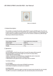
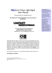
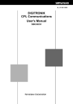
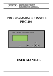
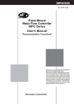
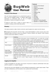
SAFETY PRECAUTIONS CP-SP-1166E Safety precautions are for ensuring safe and correct use of this product, and for preventing injury to the operator and other people or damage to property. You must observe these safety precautions. Also, be sure to read and understand the contents of this manual. Power Gate Unit (Thyristor Type Power Regulator) PGU 410 User's Manual WARNING Warnings are indicated when mishandling this product might result in death or serious injury to the user. CAUTION Cautions are indicated when mishandling this product might result in minor injury to the user, or only physical damage to this product. WARNING • Never touch any terminal with the power turned ON. Additionally, Thank you for purchasing the Power Gate Unit (Thyristor type power regulator) PGU410. This manual contains information for ensuring correct use of the PGU410. It also provides necessary information for installation, maintenance, and troubleshooting. This manual should be read by those who design and maintain devices that use the PGU410. Be sure to keep this manual nearby for handy reference. care should be taken since the electricity is not discharged completely and the terminal may be electrically live even though the power is turned OFF. • Turn off the circuit breaker to completely shut down the external power supply to this unit before proceeding for any maintenance service of this unit. The unit is still under energized state even though it is under operation stop status by the operation command input. • Set the frequency selector switch correctly to a frequency of the power supply to be used. In particular, if this regulator is operated with 50Hz power supply when this selector switch is set at 60Hz, the output tends to increase. RESTRICTIONS ON USE • Do not attempt to touch the heat sink as it remains hot during operation or immediately after operation. This product has been designed, developed and manufactured for general-purpose application in machinery and equipment. Accordingly, when used in applications outlined below, special care should be taken to implement a fail-safe and/or redundant design concept as well as a periodic maintenance program. • Safety devices for plant worker protection • Start/stop control devices for transportation and material handling machines • Aeronautical/aerospace machines • Control devices for nuclear reactors Never use this product in applications where human safety may be put at risk. • Do not supply the power before conforming for correct wiring connections. Because incorrect wiring might cause this unit to break or to be put in the hazardous status. CAUTION • Confirm whether the power supply satisfies and conforms within the limits of specification of operating voltage. If any incorrect power supply is connected, the unit may be damaged. • Do not connect any capacitive load. If any capacitive load is connected, the current increase rate becomes large at power ON, causing the thyristor element to break. • Do not connect any inductive load having a power factor of 0.5 or less. If such inductive load is connected, the phase deviation between the current and voltage becomes large, causing the phase angle to be controlled incorrectly. • Do not operate this unit in a poor noise environment. If a surge voltage is applied to the load or power supply, the thyristor element might be turned ON. REQUEST Ensure that this User's Manual is handed over to the user before the product is used. Copying or duplicating this User's Manual in part or in whole is forbidden. The information and specifications in this User's Manual are subject to change without notice. Considerable effort has been made to ensure that this User's Manual is free from inaccuracies and omissions. If you should find any inaccuracies or omissions, please contact Yamatake Corporation. In no event is Yamatake Corporation liable to anyone for any indirect, special or consequential damages as a result of using this product. CONVENTIONS USED IN THIS MANUAL The following conventions are used in this manual: Handling Precautions Handling Precautions indicate items that the user should pay attention to when handling the power gate unit PGU410. Note Note indicates useful information that the user might benefit by knowing. (1), (2), (3) The numbers with the parenthesis indicate steps in a sequence or indicate corresponding parts in an explanation. 2004 Yamatake Corporation ALL RIGHTS RESERVED 1 1. Overview This power gate unit, thyristor type power regulator model PGU410, is a power regulator using the phase angle control system, which is controlled by a control signal input of 4 to 20mA or manual setting device (QN740A101). 2. Part names and external dimensions (Unless otherwise specified particularly, the tolerance is ±1. Unit: mm) 4.3±0.2 dia. Input/output terminals: Connect the control signal input, operation command input, and overcurrent, heater burnout, and/or element short-circuit failure outputs*1. Cover for display setup section: This cover protects the adjustment and setup volumes. Remove this cover before starting the adjustment and setup. Main circuit terminals: Connect the main circuit load and power supply. *1: Optional 10.5 170 160 150 Terminal short-circuit bar 4.4±0.2 75 34 68 97 2 ● Detailed description of display setup section (Protection cover for display setup section is removed.) Power lamp: Lit in green while the power is being supplied. Frequency selector switch: Set the frequency suitable for the power supply to be used. Set at 50Hz. Set at 60Hz. Ramp output setup volume: Set the ramp showing the ratio of change in main circuit output to the control signal input. As the ramp output setting is changed, it may interfere with the low limit output setting. The default setting is that the ramp is set at its maximum level (volume position: turned clockwise fully). Low limit output setup volume: Set the main circuit output when the control signal input is the low limit (4mA when using 4-20mA input or 0% when using manual setting device). As the low limit output setting is changed, it may interfere with the ramp output setting. The default setting is that the main circuit output is 0% (volume position: approx. 40% position) when the signal control input is 5mA. Soft-up setup volume*2: Set the soft-up time. With this setting, changes in main circuit output can be made gentle when the power is turned ON or the control signal input is increased. Additionally, this function is not activated when the control signal input is decreased. The default setting is that the soft-up time is set at its minimum level (volume position: turned counterclockwise fully). Element short-circuit failure indictor*1: Lit in red if the thyristor element short-circuit failure is detected. Heater burnout indictor*1: Lit in red if the heater burnout is detected. Heater burnout detection level setup switch*1: Set the heater burnout detection level. Over-current indictor*1: Lit in red if the over-current is detected. Heater burnout detection adjustment volume*1: Used to adjust the heater burnout detection level. Heater burnout detection adjustment lamp*1: Used when setting the heater burnout detection. (Yellow) Heater burnout detection fine adjustment volume*1: Used to perform the fine adjustment of the heater burnout detection adjustment volume. Reset switch*1: Resets the heater burnout detection, over-current detection, and/or element failure detection ON status. *1: Optional *2: Not available for the high-speed type. Output voltage (%) Output voltage (%) Handling Precautions • When setting up the ramp output and low limit output, it is necessary to alternately set up the ramp output and low limit output repeatedly while monitoring the main circuit output since the ramp output and low limit output interfere with each other. Control signal input (mA) Control signal input (mA) Relationship between low limit output setting and output voltage (Basic type and high-speed type) Output current (%) Output current (%) Relationship between ramp output setting and output voltage (Basic type and high-speed type) Control signal input (mA) Control signal input (mA) Relationship between low limit output setting and output current (Constant current type) Relationship between ramp output setting and output current (Constant current type) 3 3. External wiring ■ Wiring of control signal input and operation command input ● 4 to 20mA input is used. ● Ramp setting device (QN740A105) is used. ● Manual setting device (QN740A101) is used. 3 2 Shortcircuit bar + 4 to 20mA dc – Ramp setting device* 1 2 + 4 to 20mA dc – 3 1 2 2 3 3 4 4 5 5 6 Operation command input 1 1 Operation command input 7 Manual 3 setting device* 1 6 Operation command input 7 2 4 5 6 7 * Turning the setting device clockwise will increase the set value while turning it counterclockwise will decrease it. ■ Wiring of over-current output, heater burnout output, element short-circuit output and reset input (with optional functions mounted) Heater burnout Load for output 8 alarm output Element short-circuit output Load for 9 alarm output Handling Precautions • When connecting a semiconductor load, such as programmable controller to the load for the alarm output, always select a proper module meeting the current direction. Over-current output Load for 10 alarm output + – 11 12 to 24Vdc 12 Alarm reset input 13 Internal circuit ■ Wiring of power supply and load ● 100/110Vac power supply S1 S1 U1 S2 U2 FG ● 200/220Vac power supply Main circuit load 100/110Vac 50/60Hz U1 S2 U2 FG ■ Wiring Precautions Main circuit load 200/220Vac 50/60Hz Handling Precautions • If a voltage of 200/220Vac is applied to the (S1) terminal, this might cause the unit to break. • Set the frequency selector switch to a frequency of the power supply to be used. ■ Recommended crimp type terminal lug Always use an appropriate crimp terminal suitable for the following dimensions: • Do not use unused terminals as relay terminals. • Prepare a power supply having a sufficient capacity. • Keep the low-voltage signal line 50cm or more away from the power line. • Carry out the grounding work as described below: Grounding resistance : less than 100Ω Grounding cable : Annealed copper cable with crosssectional area of 2mm2 or more (AWG14) Length of grounding :max. 20m cable Input/output terminal (M3 screw) (Unit: mm) Main circuit terminal (M4 screw) (Unit: mm) Handling Precautions • The following shows the proper tightening torque levels of the terminal screws: M3 screw: 0.6N•m or less M4 screw: 1.4N•m or less If the tightening torque exceeds the above level, this might cause the terminal screw to break. 4 4. Setting up the heater burnout detection function This heater burnout detection function outputs “heater burnout output” and turns on “heater burnout” indicator at the same time if the current flowing through the load becomes the preset value or less. ■ Setting up the detection level (1) Make sure that the conduction angle of this unit is 1/6π or more. Set the burnout detection level setup switch (LEVEL) to the ADJ position. Fully turn the adjustment volume (ADJ) clockwise. Fully turn the fine adjustment volume (FINE) counterclockwise. (2) Turn the adjustment volume (ADJ) counterclockwise until the adjustment lamp (ADJ) is lit. (3) Turn the fine adjustment volume (FINE) clockwise until the adjustment lamp (ADJ) is lit thinly. (4) Set the burnout detection level setup switch (LEVEL) to a required detection level to be set. The ratio of the load during setup to the load level to be detected can be set in a range of 25 to 95% at intervals of 5%. Setting position Relationship between heater burnout detection level setup switch and detection level Note If the control signal input is set to approximately 25% or more when operating the basic type (PGU410A) or high-speed type (PGU410H) with default settings before shipment, it is possible to set the conduction angle waveform of this unit to 1/6π or more. The heater burnout detection signal is output during setup. When the reset inputs are short-circuited, the setup can be made without outputting of the heater burnout detection signal. Handling Precautions The resistance value may greatly vary due to the temperature characteristics depending on the heater type. If such heater is used, changes in resistance value caused by temperature must be taken into consideration. 5. Troubleshooting Symptom Main circuit output signal is not output. Main circuit output does not meet the control signal. Main circuit output is too large or too small. Probable cause Corrective action • Input/output terminals 6 and 7 are not short-circuited. • Correct the wiring. (Operation command inputs are not short-circuited.) • When using 4 to 20mA input, input terminals 1 and 2 are not short-circuited. • Frequency selector switch setting does not meet the • Set the frequency correctly. power frequency. 5 6. Specifications ■ Model selection table I (Example) PGU410A II III IV 015 0 000 I II III IV Basic model No. Rated current Rated voltage Option Contents PGU410A Single-phase basic thyristor type power regulator PGU410H Single-phase high-speed thyristor type power regulator PGU410C Single-phase constant current thyristor type power regulator 015 Rated current of main circuit: 15A 030 Rated current of main circuit: 30A 0 100/110Vac or 200/220Vac * 000 No optional functions are mounted. 100 Over-current detection, heater burnout detection, and element short-circuit failure detection functions are provided. * The rated voltage is set to 100V-system or 200V-system by changing the tap. ■ Specifications Model Model Basic model No. Rated current of main circuit Rated voltage of main circuit Feedback Control signal input Input Output Signal Input impedance Number of phases and wire method Rated power supply voltage Operational power supply voltage Rated frequency Adjustment range Min. applicable load Allowable load power factor Off-state leak current Temperature vs output characteristics (See Fig. below.) Basic type PGU410A High-speed type PGU410H 15A or 30A 100/110Vac or 200/220Vac — — 4 to 20mAdc 240Ω ±5%, 1/2W Single-phase 2-wire method 100/110Vac or 200/220Vac selectable 90 to 121Vac or 180 to 242Vac 50±1Hz or 60±1Hz 0 to 98% or more of supply voltage Load with a load current of 1.0A or more 0.5 to 1.0 (delay only) Rated current of main circuit 15A Leak current value 20mA or less Mounting clearance Vertical: 80mm Horizontal: 100mm Vertical: 50mm Horizontal: 50mm Vertical: 50mm Horizontal: 30mm Vertical: 50mm Horizontal: 10mm Constant current characteristic output (Built-in CT, Constant current accuracy: ±3.0% FS) 0 to 100±3% of rated current 30A 30mA or less 0 to 40°C 100% or less of rated current 100% or less of rated current 100% or less of rated current 100% or less of rated current Output (%) 100 80 70 50 40 20 0 20 40 50 60 Operating ambient temperature (¡C) Constant current type PGU410C Operating temperature range 50°C 80% or less of rated current 80% or less of rated current 70% or less of rated current 50% or less of rated current 55°C 70% or less of rated current 50% or less of rated current 40% or less of rated current 0% of rated current Mounting clearances Vertical: 80mm, Horizontal: 100mm Vertical: 50mm, Horizontal: 50mm Vertical: 50mm, Horizontal: 30mm Vertical: 50mm, Horizontal: 10mm Handling Precautions • To use the output current, it is reduced by the mounting clearance and operating ambient temperature. At this time, the graph stated in the temperature vs output characteristics must be referred to. 6 Setting Operation command input Operation Input type Input terminal open voltage Input terminal short-circuit current Allowable contact resistance Ramp setting Allowable open collector input Setting method Setting range Low limit output setting Setting method Setting range Manual setting Setting method Setting range Soft-up setting Setting method (except for high-speed type) Setting range Frequency setting Setting method Setting range Over-current detection function Output operation Option Heater burnout detection function Element short-circuit failure detection function Open collector output specifications Alarm reset General specifications Insulation resistance Dielectric strength Heating value Cooling method Mask color Mounting Mass Operating conditions Accessories Heater burnout detection characteristics and operation Min. detection phase Min. setting phase Min. detection load current Failure detection operation time Output operation Output rating Output type Operation Open: Main circuit output OFF status Short-circuit: Phase angle control status * Even though the operation is in the main circuit output OFF status, the circuit is not shut down completely and voltage is generated by the leak current. Therefore, pay special attention to electric shock. Dry contact or open collector 8±1V (under operating conditions) 12±2mA (under operating conditions) ON: 500Ω or less (Dry contact is used under operating conditions.) OFF: 100kΩ or more (Dry contact is used under operating conditions.) Allowable open collector, Drop voltage at ON: 2V or less (under operating conditions) Allowable open collector, Leak current at OFF: 0.1mA or less (under operating conditions) Ramp output setup volume (on the front panel of the main unit) or ramp setting device QN740A105 (optional) Low limit setting is configured so that the output is 0% at 5mA. • Basic type and high-speed type: 0 to 98% or more (output voltage r.m.s. value to power supply voltage) • Constant current type: 0 to 100%±3% (output current r.m.s. value to rated current) Low limit output setup volume (on the front panel of the main unit) When the ramp setting is configured at 98% or more (basic type and high-speed type) or 100% (constant current type): Output is 20% or more at control signal input of 4mA. to Output is 0% at control signal input of 7mA or more. Manual setting device QN740A101 (Optional) Basic type and high-speed type: 0 to 98% or more (output voltage r.m.s. value to power voltage) Constant current type: 0 to 100%±3% (output current r.m.s. value to rated current) Soft-up setup volume (on the front panel of the main unit) 0.2s or less to 10s or more (with load having power factor of 1.0) Frequency selector switch (on the front panel of the main unit) 50Hz or 60Hz If the main circuit output current becomes 200% or more of the rated current for 0.2s. or longer, the gate of the thyristor is turned OFF, and the alarm output is retained on status by the open collector output and the indicator is lit at the same time. The detection level can be set in a range of 25 to 95% of the set current (at intervals of 5%). If the current becomes the set current or less, the alarm output is retained on status by the open collector output and the indicator is lit at the same time. Approx. 1/6π Approx. 1/6π 30% of rated current 0.5s If the element is turned ON continuously regardless of the control signal, the gate of the thyristor is turned OFF, and the alarm output is retained on status by the open collector output and the indicator is lit at the same time. Rated voltage of external supply: 12 to 24Vdc Allowable voltage of external supply: 10 to 29Vdc Max. load current: 70mA Allowable leak current at OFF: 0.1mA or less Drop voltage at ON: 2V or less Open collector output The alarm output is reset when the RESET switch is turned ON, the alarm reset inputs are short-circuited, or the power is turned ON again. (The alarm reset input specifications are the same as those of the operation command input.) 50MΩ or more (Insulation resistances between main circuit and chassis, between main circuit and control circuit, and between chassis and control circuit are measured using 500Vdc Megger.) Between main circuit and chassis: 2000Vac for 1min Between main circuit and control circuit: 2000Vac for 1min Between chassis and control circuit: 500Vac for 1min Approx. 13J/s (The rated current of the main circuit is 15A and the rated output is used.) Approx. 24J/s (The rated current of the main circuit is 30A and the rated output is used.) Natural convection cooling Pale purple metallic Wall mounting Approx. 1.1kg Ambient temperature 0 to 55 °C *1 Ambient humidity 10 to 90%RH (No condensation allowed.) Vibration resistance 0.00 to 1.96m/s2 Shock resistance 0.0 to 4.9m/s2 Mounting angle (Reference plane) ±10° Power supply voltage 90 to 121Vac (100/110V terminal is used.) 180 to 242Vac (200/220V terminal is used.) Power frequency 50.0±1.0Hz (Frequency is set at 50Hz.) 60.0±1.0Hz (Frequency is set at 60Hz.) Terminal short-circuit bar: 2 pcs. (Bars have been mounted between terminals 1 and 2 and between terminal 6 and 7 at shipment.) *1: 0 to 50°C for instrumentation with vertical mounting clearance of 50 mm and horizontal mounting clearance of 10mm. 7 Specifications are subject to change without notice. Advanced Automation Company Totate International Building 2-12-19 Shibuya Shibuya-ku Tokyo 150-8316 Japan URL: http://www.yamatake.com Printed in Japan. 1st Edition: Issued in Apr., 2004(A) This has been printed on recycled paper. (02)