1
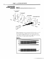
w
A ROCKWELL
INTERNATIONAL
User’s
COMPANY
Mama/
Bulletin 2755
Enhanced
MediumScan Head
(Catalog
40062-I 33-01 (A)
No.
2755~64FAA,
-i4FRA,
-L4FCA,
-L.4FDA,
2755~L4RAA,
-i4RBA,
-b4RCA, -L4RDA,
2755~LSRAA,
-LSRBA,
-LSRCA,
-LSRDA)
Publication
2755-829 - October, 1989
lmportan t User
lnforma tion
Solid-state equipment has operational characteristics differing
from those of electromechanical
equipment. “Application
Considerations for Solid-State Controls” (Publication SGI-1.1)
describes some important differences between solid-state
equipment and hard wired electromechanical
devices. Because
of this difference, and also because of the wide variety of uses for
solid-state equipment, all persons responsible for applying this
equipment must satisfy themselves that each intended
application of this equipment is acceptable.
In no event will Allen-Bradley Company be responsible or liable
for indirect or consequential damages resulting from the use or
application of this equipment.
The examples and diagrams in this manual are included solely
for illustrative purposes. Because of the many variables and
requirements associated with any particular installation,
Allen-Bradley Company cannot assume responsibility or
liability for actual use based on the examples and diagrams.
No patent liability is assumed by Allen-Bradley
Company with
respect to use of information, circuits, equipment, or software
described in this manual.
Reproduction of the contents of this manual, in whole or in part,
without written permission of the Allen-Bradley
Company is
prohibited.
Q 1989 Allen-Bradley
$25.00
Company
Table
of Contents
Chapter
I
Tit/e
Using this Manual
Chapter Objectives ...............................
.........................
Overview of This Manual
Intended Audience ...............................
Warnings and Cautions ...........................
Danger and Caution Labels .......................
2
2-l
2-l
2-3
2-4
2-5
2-5
2-6
How the System Operates
Chapter Objectives ...............................
How the Scan Head Operates ......................
Positioning Symbols Correctly .....................
4
l-l
l-l
l-2
I -2
1-3
Description
Chapter Objectives ...............................
Overview
.......................................
Lens Combinations ...............................
Reading Distance ................................
Features ........................................
Cabling .........................................
Accessories ......................................
3
Page
3-1
3-l
3-1
Installing the Scan Head
Chapter Objectives ...............................
Warnings and Cautions ...........................
Before You Start .................................
ToolsYou Will Need ..............................
How to Handle Excessive Noise ....................
Grounding Recommendations .....................
Connecting Your Equipment ......................
Determining Space Requirements
.................
Installing the Scan Head ..........................
How to Install the Swivel Mounting Base ...........
Using the Flat Mounting Plate .....................
Installing the Package Detect Assembly ............
4-1
4-1
4-l
4-2
4-2
4-2
4-2
4-3
4-4
4-4
4-5
4-6
Tab/e of Contents
Chapter
5
Page
Title
Maintenance
and Troubleshooting
..............................
Chapter Objectives
......................
Maintaining the Equipment
Scan Window Removal ...........................
Cleaning the Glass Window .......................
Cleaning the Plastic Window ......................
Troubleshooting the System ......................
6
Specifica Cons
Scan Head
......................................
5-1
5-l
5-l
5-2
5-3
5-4
6-l
-
Chapter
Using This Manual
I
-
Chapter Objectives
Overview
of This Manual
Read this chapter to familiarize yourself with the rest of the
manual. You will learn about:
l
Contents of the manual.
l
Intended audience.
l
Warnings and cautions.
This manual is for Catalog No. 2755-L4FAA, -L4FBA,
-L4FCA, -L4FDA, -L4RAA, -L4RBA, -L4RCA, -L4RDA,
-L5RAA, -L5RBA, -L5RCA, and -LSRDA Enhanced
Medium-Speed Scan Heads.
1 Chapter
1
I ’ I
-
I * I
I 3 I
Title
Using This Manual
Provides an overview of
the manual.
Description
Features and capabilities
are described.
How the System Operates
I 4 I
Installing the Scan Head
I 5 I
Maintenance and
Troubleshooting
6
I
Purpose
Specifications
Glossary
Index
Bar code operation
is
Rules and recommendations are detailed.
Troubleshooting
guidelines are provided.
Electrical, mechanical,
environmental and operational information is
listed.
Chapter
Intended Audience
Warnings and Cautions
Using This Manual
1
No special knowledge is needed to read this manual and
follow its directions. If the system will be used to
communicate with a higher level controller, we assume you
are familiar with communication terminology.
-
Both warnings and cautions are found in this manual and on
the equipment. The following symbols are used:
A
n
CAUTION:
This laser caution symbol appears
where laser radiation is present.
WARNING:
A warning symbol means people
might be injured if the procedures
are not followed.
CAUTION:
A caution symbol is used when
machinery could be damaged if
the procedures are not followed.
7
0
7
0
_
Chapter
-
Danger and Caution
Labe/s
1
Using This Manual
7-3
The scan head is labeled in accordance with federal
regulations. If any label is removed, lost, or becomes
illegible, order a replacement from your Allen-Bradley
representative. Figure 1.1 shows location of the labels on the
scan head.
n1
No user maintenance of the scan
head is required. Do not open the enclosure!
WARNING:
l
WARNING:
Improperly controlling, adjusting,
or operating the scan head can result in
hazardous radiation exposure.
Figure 1 .l
Location of Warning and Caution Labels on the Scan Head
WARNING
I \
HIGH VOLTAGE POWER SUPPLY
DISCONNECT POWER AND DISCHARGE
ANODE BEFORE SERVICING
Chapter
2
Description
-
Chapter Objectives
Overview
The capabilities of the scan head are described when
connected to a Catalog No. 2755DMl or DM6 Decoder.
The Enhanced Medium-Speed Scan Head is a moving beam,
bar code scan head capable of scanning symbols up to 50
inches away, when connected to a Catalog No. 2755-DMl or
-DM6 Decoder. Scanning is bi-directional at approximately
200 scans per second. Scan heads are available in 3 different
configurations:
l
l
l
Front scanning (Catalog No. 2755-L4FxA*)
Side scanning (Catalog No. 2’755-L4RxA*)
Raster scanning (Catalog No. 2755-L5RxA*)
* The x stands for one of 4 different range selections,
The range selections, A through D, are illustrated
in Figure 2.1
-
The front scaltlting model allows the beam to exit through
the front of the scan head. The side scalznirtg model uses an
additional mirror to reflect the beam out the side of the scan
head. The raster scanning model uses a mirror, oscillating at
20H2, to project what appears to be a number of parallel
beams. This type of scan head is useful when attempting to
scan poor quality or misaligned labels. Chapter 3 explains
how to correctly position labels and illustrates a raster
pattern (figure 3.6) created by a raster scan head.
Figure 2.1 illustrates the average reading ranges, relative
to the symbol’s minimum bar width, that you should expect
when using a Catalog No. 2755-DMl or DM6 Decoder.
Not all symbols or applications are perfect, so, slight
variations in the the reading distances will occur.
Chapter
2
Description
Overview
(continued)
Figure 2.1
Average Scan Range vs. Minimum
Bar Width
Minimum
Bar Width
(mils)
...... .:............
5
10
15
20
25
30
. ...........
35
Scan Range (inches from scan window)
0
0
@
. ..........
. ............
40
45
50
@@ @
Distances WIII be reduced by 10% on all side scanning models (2755-L4R, -LSR)
Scan Range will vary with symbol quality. This appllcatlon was based on no more than 30” pitch
and 20” skew.
For applications outslde of the designated areas, and for applications using a 2755-DMl to
decode UPC or Code 128 labels, consult the factory.
Chapter
2
Description
2-3
-
Lens C2 mbina tions
Table 2.A compares the minimum bar width to the scan
range of each catalog number.
‘able 2.A
755-L4 Catalog Number identification
Minimum
Bar Width
7.5 mil
10mil
20 mil
Scan Ran e
(inches)@@
83 @
6.5-8.5
6 -9
5- 12
Front Scanning
Side Scanning
Raster Scanning
2755-L4FAA
2755-L4RAA
2755-L5RAA
11 mil
20 mil
25 mil
lo- 16
8- 19
6-21
2755-L4FBA
2755-L4RBA
2755-L5RBA
20 mil
35 mil
15-32
15-50
2755-L4FCA
2755-L4RCA
2755-L5RCA
50 mil
15-50
17mil
25 mil
35 mil
lo-24
8-27
6-33
2755-L4FDA
2755-L4RDA
2755-L5RDA
0
0
0
0
Distances will be reduced by 10% on all side scanning models (2755-L4R, -LSR)
Thrsapplrcatron
gurde was based on no more
Scan Range will vary with symbol quality
than 30” pitch and 20” skew.
For applications outside of the designated areas, and for applrcatlons usrng a 2755-DMl
to decode UPC or Code 128 labels, consult the factory.
Symbol lengths greater than one half the usable beam width
range.
will
restrict the near
Chapter
2
Description
2-4
Reading Distance
Figure 2.2 shows the size and shape of the scanning window.
The black area is a no read area.
-
The Usable Beam Length (bottom of chart) is compared to the
the Reading Distance (top of chart). The Usable Beam
Length is slightly less than the total beam length. The
reading distance is measured from the scan window to the
center of the label.
Figure 2.2
Reading Distance vs. Usable Beam Length
Catalog No 2755- L4F, - L4R
Reading Distance@ @
0" 5" 10" 15" 20" 25" 30" 35" 40" 45" 50".
.
.
.
.
.
.
.
.
.
.
.
.
.
.
.
.
.
.
.
.
.
.
.
.
.
.
.
.
:
:
.
*
.
*
.
.
.
.
.
Usable
Beam
Length
.
.
.
.
.
.
.
.
:
.
.
.
.
.
.
.
.
.
.
.
.
.
.
.
.
.
.
.
1
.
.
.
.
.
.
-
:
.
.
.
:
I
NA 6'90"
14" 18" 22" 27"
31" 35" 39" 43"
Usable Beam Length
Catalog No 2755-LSR
Reading Distance @@
0" 5" 10n 15" 20" 25" 3088 3588 40" 45" 50"
.
.
.
.
.
.
.
.
.
.
.
.
:
.
.
.
.
.
.
.
.
.
.
.
.
.
.
.
.
.
.
.
.
.
.
.
.
.
.
’
.
.
.
I
Usable
Beam
length
.
.
.
.
.
.
.
.
.
.
.
.
.
.
.
.
.
.
.
.
.
.
.
.
.
NA
.
.
.
.
.
.
.
.
.
.
I
.
5" 8"
II"
14" 18"
21" 24" 27" 31" 34"
Usable Beam Length
o Measured
from the scan window
o Distances
will
to the center of bar code symbol
be reduced by 10% on all side scanning models (2755-L4R. -L5R)
2
Chapter
Description
2-5
Features
Shutter
control.
the laser beam.
Rotate this knob to prevent projection of
There are two LEDs on the back of the
scan head. They are defined in Table 2.B.
LED indicators.
Table 2.B
The LED on the Scanner
I
Label
I
PWR ON
I
VALID READ
Meaning
I
The scan head must be connected to the decoder
must be ON before this LED lights.
I Flashes momentarily
and the decoder
after any valid label IS scanned
Package Detect Port. Connect the optional Package
Detect Assembly (Catalog No. 2755-NPl) to this port to
allow the scan head to be turned on only when there is a
package present.
Figure 2.3
Scan Head Features
\
Shutter
Control
Cabling
PWR
ON
VALID
READ
Package
Detect
Port
To provide maximum installation and application
possibilities, the scan head is housed in a separate enclosure
from the decoder. The small size of the scan head allows it to
be installed in tight areas. Refer to table 2.C for information
necessary to order a cable.
Chapter
2
Description
2-6
Several accessories are available to provide installation and
operational flexibility, including:
Accessories
l
a
l
This assembly consists
of a photoelectric switch and a reflector. You use the
switch to indicate to the Decoder when a package is
present.
Package
detector
assembly.
Mounting
hardware.
A swivel ball mounting base
and flat mounting plate are available for the scan
head to provide installation flexibility.
Replaceable
Windows.
Replaceable glass and
plastic windows are available.
Table 2.C lists system accessories.
Ta bie 2.C
Accessories Available
for the Scan Head
Catalog
Description
Item
Number
2755-NPl
Package Detector Assembly
An infrared photoelectric switch and reflector.
“package present” detection.
2755-NC7
Package Detector Port
Connector
Use to connect user-supplied
head
For
package detector to scan
Universal swivel ball mount for greater installation
flexibility.
2755NM
1
2755-NM2
2755-NM3
Swivel Mounting
“T” Mounting
Flat Mounting
Base
Note: Must be used with “T” Mounting
No. 2755NM2).
Plate (Catalog
Plate
Use to mount Swivel Mounting
NM 1) to scan head.
Base (Catalog No. 2755-
Plate
Attach this plate to scan head in order to use your own
brackets, or to use the Swivel Mounting Base (Catalog
No. 2755NM 1) when you want the swivel ball close to
the base of the scan head.
2755-Cl
I 10-ft Cable
1 Connects Catalog No. 2755-DM 1 Decoder to scan head
2755C2
I 25-ft Cable
I Connects Catalog No. 2755-DM 1 Decoder to scan head
2755-CKlO
I 104% Cable
I Connects Catalog No. 2755-DM6
Decoder to scan head
2755-CK25
I 25ft
1 Connects Catalog No. 2755-DM6
Decoder to scan head
W77119-023-010
( Replacement Window
W77119-159-010
Replacement Window
Cable
0
I Anti-reflective,
optical glass replacement
Hard coated, anti-reflective,
window
Replacement
part number
window
plastic replacement
-
Chapter
Chapter Objectives
How the Scan
Head Operates
3
How the System Operates
Bar code operation is briefly described. The importance of
proper symbol positioning and movement is also discussed.
Inside the scan head is the laser, the lens and mirror system
and the electronics. The laser generates a small,
concentrated light beam that is focused and projected
through a window. This light is reflected by a label and
returned to the scan head for processing. The signal is then
sent to the decoder for further processing. Refer to figure 3.1
Figure 3.1
How the Scan Head Operates
Video generator board:
Video detector
Scanner driver
Laser enable
r --------I
Diffusely
I
reflected
( light from
I label (Diffuse
Return)
1
I
;
i
: ------ -,A
Positioning the
Symbols Correctly
As the symbols move past the scan head, they must be
correctly oriented. The laser’s line of light must cut through
all the bars and spaces in one sweep.
Laser’s line of
light cuts
through the
entire symbol
Chapter
3
How the System Operates
3-2
Positioning the
Symbols Correct/y
(continued)
For example, if the scan head is mounted so the laser beam is
in the vertical direction, then the symbol must also be
mounted vertically, commonly known as the Ladder
orientation. Figure 3.2 shows a vertically oriented system.
-
Figure 3.2
Scan Head and Symbol in a Ladder Orientation
Scan head is mounted on its narrower side
If the scan head is mounted so the beam is in the horizontal
direction, the symbol must also be in the horizontal
direction. This is termed pi&et fence orientatiort.
Refer to figure 3.3 for an example of the scan head and
symbol in a pi&et fence orientation.
Figure 3.3
Scan Head and Symbol in a Picket Fence Orientation
Scan head is mounted on its wider side
-
Chapter
How the System Operates
3
3-3
-
Positioning the
Symbols Correct/y
(continued)
When setting up a front or side scanning model, you should
attempt to have the laser line of light perpendicular to the
bars and spaces of the symbol. For optimal performance,
mount the scan head at a 10” to 20” angle off normal from the
label, as shown in figure 3.4.
Figure 3.4
Proper Mounting
of Scan Head
Label
-
The scan head can successfully decode symbols that are up to
+ 50” out of alignment, provided that the projected, or
apparent, bar element widths are within the minimum
widths shown in table 2.A. Symbols that are pitched or
tilted up to * 45”, are still readable. Skewed symbols can
also be read as long as the misalignment is less than * 50”.
Figure 3.5 shows a correctly placed symbol as well as
misaligned symbols.
n
t
l
WARNING: If at any time during operation an
intense dot of light is reflected onto a label
instead of a line of light, rotate the shutter
control knob on the scan head to close the scan
window. Then turn the decoder OFF.
Chapter
3
How the System Operates
3-4
Positioning the
Symbols cOWect/y
(continued)
Figure 3.5
Examples of Correctly Positioned and Misaligned
Symbols
Skewed package
and symbol
Correct/y positioned
symbol and package
-
When setting up a raster scaning model, the pattern created
by the raster can overlap the entire symbol, to aid in the
scanning of misaligned symbols, or be restricted to cover
only a portion of the label, which is helpful when scanning
symbols of poor quality. Refer to figure 3.6
Figure 3.6
-Riaster pattern
\
Chapter
Chapter Objectives
Installing the Scan Head
4
Carefully read this chapter before installing the system. We
will present rules and recommendations for installing and
connecting the scan head.
Warnings and Cautions
l
1
A
l
l
WARNING:
Do not make adjustments to the
equipment. Only use procedures specified in
this manual.
WARNING: If at any time during operation
an intense dot of light is generated instead of
a thin line of light, immediately close the
shutter control on the scan head and remove
power.
Do not look directly into the laser
beam since you could damage your eyes.
CAUTION:
A
A
1
0
1
0
Before
YOU
Start
CAUTION: No user maintenance of the
hardware is required. Do not open the unit’s
housing!
WARNING: Do not open the unit’s housing.
No user maintenance of the scan head is
required.
The angle and distance between the scan head and the labels
is an important consideration. These considerations,
orientation and alignment, are described in Chapter 3.
Chapter
4
installing the
ScanHead
4-2
Wi// Need
Normally, the only tool you will need for installation is an
adjustable, open-ended wrench. If the optional Swivel
Mounting Base and Plate are used (Catalog No. 2755NM1
and 2755NM2), you will also need a screwdriver and a 3/l&
inch allen wrench.
HOW to Hand/e
When the system is operating in a noise-polluted industrial
environment, special consideration should be given to
possible electrical interference. The effect of electrical
interference has been minimized by the basic design of the
hardware. Properly grounding the equipment, correctly
routing wires and the use of shielded cables will also help
minimize interference.
TOO/S YOU
Excessive Noise
Grounding
Recommendations
Grounding is an important safety measure in electrical
installations. With solid-state systems, grounding also helps
limit the effects of noise due to electromagnetic interference
(EMI).
An authoritative source on grounding requirements is the
National Electrical Code published by the National Fire
Protection Association of Boston, Massachusetts. Article
250 of the Code discusses the types and sizes of wire
conductors and safe methods of grounding electrical
equipment and components.
Connecting
Your Equipment
Connect your equipment using the appropriate cables.
Follow the step-by-step procedure described below.
Step 1
Connect the scan head to the port labeled SCAN
HEAD on the back of the decoder.
Step 2
Connect the terminal that will be used for
programming to the proper port on the decoder
(refer to the User’ Manual supplied with your
decoder).
Step 3
The initial programming should be done at this
time, if it was not done earlier (refer to the User’s
Manual supplied with your decoder).
-
Chapter
4
Installing the Scan Head
4-3
Connecting
Your Equipment
Step 4
If a host computer will be used, connect it to the
port labeled COMM on the back of your Catalog
No. 2755-DMl decoder, or the port marked HOST
on your Catalog No. 2755-DM6 decoder (refer to
the User’s Manual supplied with your decoder).
Step 5
If output devices will be used, connect them to the
decoder (refer to the User’s Manual supplied with
your decoder).
Step 6
If a package detector will be used, connect it to the
small port on the scan head.
(continued)
The decoder and scan head are separate units that can be
mounted on separate surfaces. A lo- or 25-foot cable is used
to connect the two units. Figure 4.1 illustrates the
dimensions of the scan head.
Determining the
Space Requirements
Figure 4.1
Mounting Dimensions of the Scan Head
-e-m-
.+)--------?--I
I
I
I
i
I
Side Scanning Model
2 13"
I
I
All Models
f
t
;M
I
3 75"
.75"
I
1
I
-e-m
:
T
2 19"
:
~
I,
225” 4
Front Scanning Model
1
----
Location of beam In
Scanning Window
(A/! Models)
Chapter
4
Installing
the Scan Head
4-4
Installing the
Scan Head
Before installing the scan head, review the following
information:
-
Determine the optimum position of the scan head
relative to the labels that are to be read. Refer to
Chapter 3 for positioning information.
If you are using the optional swivel base or brackets,
add their dimensions into your positioning
calculations.
Allow a minimum clearance of 8 inches at the rear of
the scan head so you can attach the cables to the
various ports.
Securely mount the scan head to a rigid surface to
ensure proper operation of the scanning mechanism.
Because the thickness of the mounting surface (table top,
shelf or bracket) determines the length of the screws or bolts
required, fasteners are not supplied with the scan head.
You will need two IO-32 hexagon-head cap screws, with flat
and split washers. Select a length that equals the thickness
of the mounting surface, thickness of the washers plus s/8inch (depth of screw holes).
HOW to /nsta// the
Swivel Mounting Base
(Catalog No. 2755-NM I
and 2755-NM2)
For greater installation flexibility, you can attach the
scan head to an optional Swivel Mounting Base. The
installation dimensions of the Swivel Base and its
associated “T” Mounting Plate are shown in Figure 4.2.
-
Chapter
4
Installing the Scan Head
4-5
Figure 4.2
Mounting Dimensions
of Swivel and “T” Mounting
-41.00
r
- -r
I.
n
N
i
/-
r
7/G
Swivel Mounting
-
180
-20
UUF-
DIA
2A
Base
Using the Flat
Mountmg P/ate
(Ca ta/og No. 2755- NM21
Plate
-WI
4
.-I5
I---
l-7'"
'
3.
“T” Mounting
Plate
A Flat Mounting Plate is also available. By attaching this
plate to the bottom of your scan head, you can position the
swivel mounting ball close to the base of the scan head. You
may also use the Flat Mounting Plate when you want to
mount the scan head with brackets of your own design.
The dimensions are shown in Figure 4.3.
Figure 4.3
Mounting Dimensions
of the Flat Plate
Chapter
4
Installing the Scan Head
4-6
Installing the Packa e
Detect Assem Bly
(Catalog No. 2755-NM)
The Package Detect Assembly consists of:
1. A self-contained photoelectric switch.
2. A 3-inch diameter reflector.
The switch has the following specifications:
l
Maximum operating range: 18 feet.
l
Operating temperature: -13” to 158” F (-25” to 70” C).
l
Tolerance to ambient sunlight: 10,000 foot candles.
When installing the switch, we recommend you observe the
following guidelines:
l
l
l
Install the switch at an angle to the labels to minimize
the affect of light reflecting off the labels.
Install the reflector so it does not exceed its operating
range.
The package detector beam must be broken before the
label is in position to be read.
-
Figure 4.4 shows a typical package detector installation.
Figure 4.4
Recommended
Placement of the Package
Detect Switch and Reflector.
Reflector@
Photoelectric
A
Scan Head
Switch
-
Chapter
4
Installing the Scan Head
4-7
-
Installing the Packa e
Detect Assem t?ly
Figure 4.5 specifies which pins on the Package Detector Port
Connector (Catalog No. 2755NC7) are used.
(Catalog No. 2755-NPI)
(continued)
Figure 4.5
Pins Used on Package Detector Connector
+ 12v
1
I
c
Common
2
I
t
3
’
Package Detect Input @
I
Package Detect Port on Scan Head
3
If trlggerlng on package detect, with Pin 3 open, no bar code lnformatton
IS decoded
and the Package Detect LED is OFF. The package detect input must be pulled low In
order to decode informatlon.
The package detect LED on the Decoder WIII light
when the package detect Input IS active.
Note: If the laser is programmed to be ON only upon a
package detect, the laser will be OFF until the
package detector is triggered.
-
Chapter
5
Chapter Objectives
Maintenance procedures are stated and troubleshooting
charts are provided in this chapter.
Maintaining the
Equipment
No user maintenance of the scan
head is required. Do not open the enclosure!
WARNING:
t
n
Scan Window
Removal
Maintenance and
Troubleshooting
l
The scan window fits into a cut-out in the front or
side of the scan head. A gasketed cover is then tightly
secured over the window to ensure a Nema 12/13 rating.
To remove the scan window:
1. Remove the six Phillips head screws from the cover.
,-
2. Lift the cover away from the scan head. Handle the
scan window by the edges to avoid finger prints.
Make sure the scan window does not fall out. Refer to
figure 5.1
Figure 5.1
Scan Window
Chapter
5
Maintenance
and Troubleshooting
5-2
Cleaning the
Glass Window
Do not use abrasive materials, such as disposable paper
wipes, to clean the glass scan window. Most disposable
wipes, or paper towels, use glass fibers which will scratch
and cloud the window. Instead, you may use the following
materials:
Solvent:
Wipe:
-
Isopropyl alcohol (100% solution).
Optics quality lens cleaning paper and
cotton-tipped swabs.
Use the following procedure to clean the glass:
At
0
Do not use abrasive materials, such
as disposable paper wipes, to clean the glass scan
window. Most disposable wipes, or paper towels,
use glass fibers which will scratch and cloud the
window.
CAUTION:
Step 1
Turn the decoder OFF. The switch is located on the
rear of the decoder.
Step 2
Check that the PWR ON indicators on both the
decoder and scan head are OFF.
Step 3
Remove the scan window. Figure 5.1 illustrates
the removal.
Step 4
Use the lens cleaning paper to wipe any dust or
foreign material from the window. Be careful not
to scratch the window with any grit that might be
on the window.
Step 5
For stubborn film and finger prints, use isopropyl
alcohol (100% solution) and cotton-tipped swabs.
To avoid smearing film and fingerprints, rotate the
cotton-tipped swab, while it’s on the glass, nearly
one revolution then discard it.
Step 6
Replace the scan window.
Step 7
Turn the decoder ON. The PWR ON indicators on
both the decoder and scan head should be ON.
Note:
When the window is clean, you will barely be able
to see the reflection of the laser beam on the clear
glass.
-
Chapter
5
Maintenance
and Troubleshooting
5-3
-
CIeaning the
P/astic Window
Do not use abrasive materials, such as disposable paper
wipes, to clean the plastic scan window. Most disposable
wipes, or paper towels, use glass fibers which will cloud and
blur the window, thus reducing the effectiveness of the scan
head. Instead, you may use the following materials:
Air:
Solution:
Wipe:
Optics rated clean air
Optics rated cleaning solution designed for
use on plastic coated lenses
Optics quality lens cleaning paper designed
for use on plastic lenses
Use the following procedure to clean the plastic window:
t
n
l
CAUTION: Do not use organic solvents on the
plastic window.
CAUTION: Do not use abrasive materials, such
as disposable paper wipes, to clean the scan
window. Most disposable wipes, or paper towels,
use glass fibers which will scratch and cloud the
window.
-
Step 1
Turn the decoder OFF. The switch is located on the
rear of the decoder.
Step 2
Check that the PWR ON indicators on both the
decoder and scan head are OFF.
Step 3
Remove the scan window. Figure 5.1 illustrates
the removal.
Step 4
Use the optics rated clean air to blow any any dust
or foreign material off of the window.
Step 5
For stubborn film and finger prints, apply any
optics rated cleaning solution designed for plastic
lenses. To avoid smearing film and fingerprints
you should blot, not rub, the surface of the window.
Each time you blot the surface, use a new (dry)
section of the optics quality lens cleaning paper.
Step 6
Replace the scan window.
Step 7
Turn the decoder ON. The PWR ON indicators on
both the decoder and scan head should not be ON.
Note: When the window is clean, you will barely be able
to see the reflection of the laser beam in the
window.
Chapter
5
Maintenance
and Troubleshooting
5-4
Troubleshooting the
System
Probable Cause
Problem
)WR ON indicators
In both scan head
3nd decoder do not
ight.
DWR ON indicator on
;can head does not
fight, but PWR ON
Indicator on decoder
15lit.
Decoder is not turned ON.
Turn decoder ON.
improper connection to power
suPPlY*
Reconnect power cord to source.
Line fuse on decoder is blown.
Replace fuse on decoder:
Faulty power cord or switch.
No incoming power.
Check that voltage is present at
service outlet.
Interconnect cable between decoder
and scan head is loose.
Reconnect cable and check
connections.
interconnect
Replace cable.
cable is damaged.
Scan head is damaged
Replace scan head
Shutter on scan head is closed.
Rotate shutter
No scan trigger signal.
Verify sending of scan trigger by
either package detect or host
command.
No laser beam
emitted from
window of scan head
Improperly
Unable to read a
label.
Laser beam expands
and contracts.
Warning!
Laser beam is an
intense dot of light.
Possible Solution
positioned
labels.
control knob.
Check that reading distance is
correct and orientation of labels to
scan head is correct.
Poor quality labels.
Check that labels are good quality
and within specifications.
Shutter control knob is not fully
open.
Rotate shutter control knob on
Scan head.
Decoder is improperly
Refer to the appropriate
Manual
programmed.
User’s
Loose cables or connections.
Check cables and connections.
Shutter on scan head is not fully
open.
Rotate shutter control knob.
Scan head is not securely mounted.
improve mounting.
Laser scanning mechanism is not
operating correctly.
Rotate shutter control knob in
order to close window and then
turn decoder OFF.
-
Chapter
6
Specifications
Chapter Objectives
Scan Head
Electrical
Receives power from decoder.
(Catalog No. 2755-L)
Mechanical
Cast aluminum
Enclosure
LED Indicators
l
Power On
l
Valid Read
NEMA 12/13
Weight
4lhs(Ukg)
Dimensions
10.25” x 4.25” x 2.50”
(26.0 x 10.8 x 2.50 cm)
Environment
Ambient temperature range, 32” to
122°F (0” to 50°C)
Meets Class II standards
CDRH
Standards
Optical
Light Source
Power
Fixed Scan Rate
Scan sweep angle
Focused helium-neon (He-Ne) laser
(632.8nm)
1.5 mW max.
200 scans/second, +_ 5%
Raster at 20 cycles per second
Front scanning unit 47”
Side scanning
-
unit 47”
Raster scanning unit 40”
5” to 50” from scan window oo
5” to 50” from scan window oo
Scan Range
Depth of Field
5” to 50” from normal 0
Label Skew
Label Pitch
5” to 45” from normal 0
Package Detect
Min. OFF-State
Voltage
Max. ON-State Voltage
11 VDC
2 VDC
0
Depending
0
Distances
will be reduced
side scanning
models
on the model
0
Depending
selected
on label quality
by 10% on all
G
Glossary
A
AIM
Acronym for Automatic
Identification
Manufacturers.
alignment
The relative position of a scanner or light source to the target or the
receiving element.
alphanumeric or alphameric
The character set which contains letters, digits, and other characters
such as punctuation marks.
aspect ratio
The ratio of height to width of a bar code symbol. A code twice as high
as wide would have an aspect ratio of 2; a code twice as wide as high
would have an aspect ratio of + or 0.5.
attended system
A Scanner/decoder
an operator.
combination
that must be activated, or attended,
by
average background reflectance
Expressed as a percent, this is the simple arithmetic average of the
background reflection reading from at least five different points on a
sheet.
average edge
An imaginary line bisecting the irregularities
8
background
The area surrounding
of the character edge.
a printed symbol.
bar
The dark element of a printed symbol.
bar code
The vertical bars and spaces found in a bar code symbol.
bar code density
The number of characters which can be represented
in a lineal inch.
bar code label
A label that carries a bar code and is sui table to be affixed to an article.
bar code reader
A device used to identify and read a bar code symbol. Also know as a
decoder
bar code symbol
A group of vertical bars ,that represents a character or group of
characters whose spacing is determined by a specific set of rules. In most
cases, human readable characters are also printed below the bars.
bar length
The bar dimension
perpendicular
to the bar width.
G
Glossary
G-2
bar width
The thickness of a bar measured from the edge closest to the symbol’s
start character to the trailing edge of the same bar.
bi-directional symbol
A bar code symbol that can be read in complementary
binary code
A power-of-two
code; each bit position has a weighted
(two) directions.
value.
bit
An acronym for Binary Digit. The smallest unit of information in the
binary numbering system. Represented by the digits 0 and 1.
C
CCD
Acronym for Charge Couple Device; a linear image sensor that scans at
high speeds (approximately 4,000 times per second) and detects the
presence or absence of marks passing under the device.
character
A single group of barsand spaces representing an individual number,
letter or punctuation mark. A graphic shape representing a letter,
number or symbol.
character alignment
The vertical or horizontal
reference Ii ne.
position of characters with respect to a given
character density
The dimension, in linear inches, required to encode one character.
character reading
Reading of alpha or numeric characters,and/or
means.
symbols, by optical
character set
Those characters available for encoding purposescharacter skew
See skew.
character spacing
The horizontal distance between two adjacent characters.
check digit
A digit included within a symbol whose value is based mathematically
on other characters included in the symbol. It is used to mathematically
check the accuracy of the read.
clear area
A clear space, containing no dark marks, that precedes the start
character of a symbol and follows the stop character. That region of a
document reserved for OCR characters and the required clear space
around these characters.
-
G
Glossary
G-3
-
code
A set of rules governing how the bars and spaces of the symbol will
represent characters and groups of characters. bar code.
code medium
The material used to construct a machine readable code. Such materials
may be retroreflective or opaque.
code reader or scanner
A device that examines a spatial pattern, one part after another, and
generates analog or digital signals corresponding to the pattern.
contact scanner
A code reader that requires physical contact with the code medium.
continuous code
A bar code or symbol that does not use an intercharacter gap between
characters in the code. Code 128 is an example of intercharacter gap.
D
decoder
An unattended device used to decode, or make usable, a diqital or
analog signal transmitted from a scanning device.
-
decoder logic
The electronic package which receives the signals from the scanner,
interprets the signals into meaningful data and provides the interface to
other devices.
depth of field
The distance between the maximum and minimum
symbol can be read.
plane where a
diffuse reflection
Reflection of liqht in all directions. Diffuse reflection
glossy surfaces: (Also see specular reflection)
occurs from non-
dirt
In paper, refers to the presence of relatively non-reflective foreign
particles imbedded in the sheet. The size and lack of reflectance of the
particles may cause the optical scanner to mistake the dirt for inked
areas.
discrete code
A bar code or symbol where the space between characters,
intercharacter gap, are not part of the code; as with Code 39. (Also see
continuous code)
diverging beam
A beam of light that is optically controlled
different directions from the source.
so the light extends in
G
Glossary
G-4
r
t
EAN
Acronym for European Article Numbering System, the international
standard bar code for retail food packages.
edge error
Irregularities
with respect to the average edge of an element.
element
1) A single binary position in a character. 2) Dimensionally
narrowest width in a character, bar or space.
the
encoded area
The total linear dimension consisting of all the characters of a code
pattern, including start/stop characters and data.
extraneous ink
Ink in a scan area not intended to be there.
F
first read rate
The first read rate is the percentage of bar code symbols that are read
with the first pass of the bar code wand under ideal conditions. Bar
code symbols should have a first read at least 90% of the time. A first
read rate of less than 90% usually means that either the bar code
symbols or scanning device need some type of adjustment or
modification. This does not mean that a system which has a first read
rate of less than 90% is unacceptable.
zuard bars
The bars at the ends and center of a UPC and EAN symbol. They ensure
a complete scan of the bar code.
H
hand held scanner
Refers to any scanning device that must be held over the bar code
symbol.
height-of-scan
The maximum vertical scanning dimension of a moving beam scanner at
a specific distance from the face of the scanner.
helium neon laser
The type of laser most commonly used in bar code scanners. Because the
laser beam is bright red, bars must not be printed with red ink since they
would be indistinguishable from the background.
horizontal bar code (Picket Fence)
A bar code or symbol presented in such a manner that its overall length
dimension is parallel to the horizon. The bars look like a picket fence.
I
incandescent light source
Intense white light used to illuminate
camera.
an object as it passes under a CCD
G
Glossary
G-5
-
intercharacter gap
The space between two adjacent bar code characters.
white space between two characters in AIM USS-39.
For example, the
interleaved bar code
A bar code in which characters are paired together using bars to
represent the first character and spaces to represent the second; as in
USS-I 2/5
K
key mark or trigger
A code bit(s) that provides the scanner with the instruction that the code
is in a position to be read; used in some fixed beam readers.
f
ladder orientation
See vertical bar code.
laser scanner
An optical bar code reading device using a low energy laser light beam
as the source of illumination.
-
Light Emitting Diode (LED)
A semiconductor diode generally made from gallium arsenide, that can
serve as a near infrared light source when voltage is applied
continuously or in pulses. LED’s have extremely long lifetimes when
properly operated; being solid-state, they are very resistant to shock and
vi bration.
light operated
Condition in which the control operates when the light beam in
uninterrupted.
M
mis-encodation
When the characters which were to be represented in symbol form are
not correctly encoded. Example: desired number is 1,2,3,4; the
encoded number is 1,2,5,4.
misread
A condition which occurs when the data output of a reader does not
agree with the encoded data presented. See substitution error.
module
A group of elements-The term module is used by the Uniform Product
Code Council in it descriptions of the UPC code. A module is the
narrowest unit of measure in the code. A module may be “black” or
“white”. Contiguous modules are used to form bars or spaces that are
wider than one unit.
modulo check digit or character
A calculated character within a data field used for error detection. The
calculated character is determined by applying a code algorithm to the
data field contents.
modulus 43 check character
Used in Code 39 for data security in addition to the built-in self-checking
characters. The check-character is the modulus 43 sum of all of the
character values in a given message and is the last character in the code.
G
Glossary
G-6
moving beam scanner
A device which dynamically searches for a bar code pattern by sweeping
a moving optical beam through a field of view.
N
nanometer
Unit of measure used to define the wavelength
of light.
10 -9 meters.
no-read, non-read, non-scan
The absence of data at the scanner output after an attempted
to no code, defective code, scanner fai I ure or operator error.
scan due
nominal size
The standard size for a bar code symbol. Most codes can be used over a
range of magnifications from 0.80 to 1.20, nominal.
numeric
A machine vocabulary that includes only the numbers as contrasted to
alphanumeric which includes both letters and numerals.
0
OCR
Acronym for Optical Character Reader. An information processing
device that scans and decodes human readable OCR symbols.
OCR-A
An abbreviation commonly appl ied to the character set contained
ANSI Standard x3.17- 1974.
in
OCR-B
An abbreviation commonly appl ied to the character set contained
ANSI Standard x3.49- 1975.
in
off-line
Refers to devices that operate independently
unit.
of a central processing
on-line
An operation in which peripheral devices are connected directly to the
computer central processor unit.
opacity
1) The property of paper that minimizes the show through of printing
from the back side or the next sheet. 2) The ratio of the paper
reflectance with a black backing to the paper reflectance with a white
backing.
scanning range
The sum of the scan head’s optical throw and depth-of-field.
optical throw
The distance from the face of the scanning device to the center of the
depth of field.
orientation
The alignment of bars and spaces to the scanner. Often referred to as
vertical (picket fence) or horizontal (ladder).
-
G
Glossary
G-7
-
overhead
The fixed number of characters required for start, stop and checking in a
given symbol. For example, a symbol requiring a start/stop and two
check characters contains four characters of overhead. To encode three
characters of data, seven characters are required.
P
parallel beam
A beam of light that is optically controlled so the light travels in a
parallel path. Generally used when the object is larger than the lens
diameter.
parallel code
A code configuration that is optically scanned in its entirety at one time.
Since all codes marks are read simultaneously, the code can move pass
the reader in either direction.
parity bar, parity bit, parity module
A parity bit is added to a binary array to make the sum of all the bits
always odd or always even; a fundamental check.
permanent code
A code which is indefinitely
reused in a bar code application.
picket fence code
See horizontal bar code.
-
pitch
1) Rotation of a code pattern about the X axis. 2) The normal distance
between the centerline or adjacent characters.
pre-pri nted symbol
A symbol which is printed in advance of application
on the article to be identified.
either on a label or
Print Contrast Signal (PCS)
A measurement of contrast (brightness difference) between the bars
and spaces of a symbol. A minimum PCS value is needed for a symbol to
be scannable.
PCS = (RL-RD)/ RL, where RLis the reflectance factor of the light
background and Rb is the reflectance factor of
the dark bars. PCS values can be calculated and
displayed automatically on suitable instruments.
print quality
The complete analysis of a printed symbol with regard to reflectance
properties as well as bar and space resolution with regard to symbol
specification. The inter-relationship
of printed material and imprinted
material that affects the optimum performance of the scanner.
proximity sensor
A method of object detection in which the source and detector are
located on the same side; the detector senses energy from the source
which is bounce back by the object being detected.
Q
quiet area, quiet zone
See clear area.
G
Glossary
G-8
R
raster scanner
Also available as an optional raster assembly. Raster scanners are similar
to standard scanners. The beam still travels from left to right, but it now
does so in a sinusoidal, or top to bottom, pattern. This allows the
scanner to see different scan paths so if a bar is deformed or soiled in
one place it may still be read due to the sinusoidal sweep of the beam.
read
A successful scan of a bar code symbol.
reflectance
The amount of light returned from an illuminated
surface.
reflectance, absolute
The ratio of the total reflectance by a document to the total light
incident on the document.
reflectance, diffuse
Reflected light whose angle of reflection varies from the angle of
incidence of the illuminating light; such as reflection from a non-glossy
surface.
reflectance, specular
Reflected light whose angle of reflection is equal, or nearly equal, to the
angle of incidence of the illuminating light, as in reflection from a
mirror.
reflex
A method of object detection in which the source and detector are
located on the same side; a retroreflector on the far side returns the
energy from the source to the detector.
reject
See no-read, non-read, non-scan.
resolution
1) The measure of the ability of a lens, a photographic material or a
photographic system to distinguish detail under certain specific
conditions. 2) The dimension of the smallest element which can be
printed employing a particular technique. 3) The narrowest element
dimension which can be distinguished by a particular reading device.
retro
See retroreflective.
retroreflective
Characteristic of material causing it to reflect light back to its source
regardless of angle of incidence.
retroref lector
A reflector, specially constructed, which reflects energy back to the
source from which it came. It is also known as a “corner reflector”.
reverse image
A symbol in which the normal dark areas are represented
areas.
in the light
G
Glossary
G-9
-
5
scan
The search for a symbol or marks which are to be optically recognized.
scan area
The area intended to contain a symbol.
scan head, scanner
A device that optically scans bar code symbols and converts the optical
information into digital or analog form and sends it to a decoder.
scanning curtain
The effective reading area (width x height) of a moving beam scanner,
which is equal to its depth-of-field and height-of scan at a specific
operating range.
scanning range
The combined distance of optical throw and depth of field.
scanning wand
See wand.
segment
See element.
-
self-checking
A bar code or symbol using a checking algorithm which can be applied
to each character to guard against undetected errors. Non-self-checked
codes may employ a check digit or other redundancy in addition to the
data message.
serial code
A bar code symbol typically used with a fixed beam scanner where the
scanning action is caused by the motion of the symbol past the scanning
head. The bits of the symbol are evaluated one at a time (serially).
skew
Rotation about the Y axis. Rotational deviation from correct horizontal
and vertical orientation may apply to a single character, line or the
entire encoded item.
space
The lighter element of a bar code formed by the background
bars.
between
space encoding
See interleaved bar code.
special symbol/character
In a character set, a character that is neither a numeral, letter, or a
blank: for example, @ $ % Q & *.
spectral response
The variation in sensitivity of a device to light of different
wavelengths-
specular reflection
Reflection of light from a surface at an angle equal but opposite to the
angle of incidence. See reflectance, specular.
G-IO
G
Glossary
spots
Ink or dirt spots within the spaces or clear area of a bar code which may
reduce first read rate.
4
start/stop character
A bar code character that provides the scanner with start and stop
reading instructions as well as code orientation.
stepladder code
See vertical bar code.
substitution error
This error can be seen in a mis-encodation, mis-read, or human operator
error. Characters are substituted with erroneous information.
Example:
correct information is 1,2,3,4; substitution is 1,2, 5,4. Substitution
errors are usually the result of bar code labels with printing defects.
Substitution errors are extremely difficult to determine and are usually
not found until the data has been processed and an obvious data error is
noti ted.
symbol
A combination of characters including start/stop characters and check
characters, as required, which form a complete scannable entity.
symbol density
The number of characters per linear inch.
symbol length
The length of the symbol measured from the beginning of the quiet
area adjacent to the start character to the end of the quiet area adjacent
to a stop character.
-
u
unattended system
A Scanner/decoder combination that is triggered, or activated, by an
external source such as a computer, PLC or mechanical switch.
UPC
Universal Product Code. The standard bar code symbol for retail food
packaging in the United States.
V
vertical bar code (ladder orientation)
A code pattern in which the overall coded area from start to stop is
perpendicular to the horizon. The individual bars appear as rungs of a
ladder.
void(s)
The absence of ink within printed bars. The absence of ink within the
confines of a character.
W
wand
A hand held scanning device used as a contact bar code or OCR reader.
4
Index
A
accessories . . . . . . . . . . .._..........................
2-6
alignment
. . . . . . . . . . . . . . . . . . . . . . . ..-.-......
3-l - 3-3
anti-reflective replacement windows
. . . . . . . . . . . . . . . 2-6
attaching
flatplate
. . . . . . . . . . . . . . . . . . . . . . . . . . . . . . . . . . . . . 4-5
scan head . . . . . . . . . . . . . . . . . . . . . . . . . . . . . . . . . -. -. 4-4
swivel ball
4-4
Tmountingpia;e’::::::::::::::::::::::::::::::
4-5
B
bar
code . . . . . . . . . . . . . . . . . . . . . . . . . . 2-2 - 2-4,3-l
- 3-4,
width
2-2 - 2-4,3-3
beamwidth’:::::::::::::::::::::::::::::.
2-4
brackets . . . . . . . . . . . . . . . . . . . . . . . . . . . . . . . . . i:6; 414 - 4-5
c
-
cabling . . . . . . . . . . . . . . . . . . . . . . . . . . . . . . . . . . . . . . . . . . 2-5
caution . . . . . . . . . . . . . . . . . . . . . . . . . . . . .
l-l - l-3,4-1,5-3
charts . . . . . . . . . . . . . . . . . . . . . . . . . . . . . . . . . . . . . . . 2-2,2-4
clearance . . . . . . . . . . . . . . . . . . . . . . . . ..-.............
4-4
code
2-2 - 2-3
COMM”:::::::::::::::::::::::::::::::::::::.....
4-2
configurations
. . . . . . . . . . . . . . . . . . . . . . . . . . . . . . 2-2 - 2-4
connections . -. . . . . . . . . . . . . . . . . . . . . . . . . . . . . . . . . . . . 5-4
connector . . . . . . . . . . . . . . . . . . . . . . . . . . . . . . . ..-..
2-6,4-7
considerations
. . . . . . . . . . . . . . . . . . . . . . . . . . . . . . . . . . . 4-l
cut-out
. . . ..-....................................
5-l
D
danger
. . . . . . . . . . . . . . . . . . . . . . . . . . . . . . . . . . . . . . . . . . l-3
decode . . . . . . . . . . . . . . . . . . . . . . . . . . . . . 2-2 - 2-3,3-3,4-7
decoder
2-5,3-3,4-2
- 4-3,4-7,5-2
diffusereturn’::::::::::::::::..........
3-l
DMl Decoder(expectations)
. . . . . . . . . . . . . :::::““’ 2-l - 2-4
DM6 Decoder (expectations) . . . . . . . . . . . . . . . . . . 2-1 - 2-4
E
effectiveness (reduction)
EMI . . . . . . . . . . . . . . . . . . . . . . . . . . . . . . . . . . . . . . . . . . . . .
enclosure (warning) . . . . . . . . . . . . . . _. . . . . . . . . . . . . . . .
-
5-2
4-2
l-3
F
front scanning- m1: 1:: 1:: 1: 1: 1:: 1: 1:: 1: 1: 1:
fasteners
4-4
*m
2:; Si Y4,4-3
index
I-2
G
gasketed cover ..................................
grit (removal from window)
.......................
grounding .......................................
5-1
5-2
4-2
I
illegible labels . . . . . . . . . . . . . . . . . . . . . . . . . . . _. . . . . . - 1-3
installation
. . . . . . . . . . . . . . . . . . . . . . 2-5 - 2-6,4-2,4-4‘4-6
intended audience
. . . . . . . . . . . . . . . . . . . . . . . . . . . . . . . l-2
interconnect
. . . . . . . . . . . . . . . . . _. . . . . . . . . . . . . . . . . . _ 5-4
isopropyl alcohol . . _. . . . . . . . . . . . . . . . . . . . . . . . . . . . . . 5-2
L
L4FAA ...........................................
L4FBA ........................................
L4FCA ........................................
L4FDA ........................................
L4R
L4RAA”:::::::::::::::::::::::::::::::::::::::”l--1,2-2
L4RBA ........................................
L4RCA ........................................
.......................................
L4RDA
L5R
LSRAA”::::::::::::::::::::::::::::::::::::::.
LSRBA ........................................
LSRCA ........................................
L5RDA
.......................................
laser ...............
l-2,2-5,3-1
LEDs ............................................
2-2
l-1,2-2
l-l, 2-2
l-l, 2-2
2-4
- 3-2,4-l,
l-l, 2-i
l-1,2-2
l-1,2-2
2-2 - 2-3
l-l, 2-2
l-1,2-2
l-l, 2-2
l-1,2-2
4-6 - 4-7, 5-2
2-5
M
maintenance
5-l - 5-4
minimumbarwib;h”::::::::::::::::::::::::::
2-2-2-3
misaligned
. . . . . . . . . . . . . . . _ . . . . . . . . . . . . . . . . . . 3-3 - 3-4
mounting
. . . . . . . . . . . . . . . . . . . . . . . . . . . . . . . 2-6,4-3 - 4-5
N
1-1,6-l
nema12
. . . . . . . . . . . . . . . . . . . . . . . . . . . . . . . ..-....
noise-polluted
. . . . . . . . . . . . . . . . _. . . . . . . . , . . . . . . . . . 4-2
0
optics . . . . . . . . . . . . . .
optimum position . . .
orientation
.........
oscillating . . . . . . . . . .
. . . . . . . . . . . . . . . . . . . . . . . . . 5-2 - 5-3
. . . . . . . . . . . . . . . . . . . . . . . . . . . . . 4-4
. . . . . . . . . . . . . . . . . 3-1 - 3-2,4-l, 5-4
. . . . . . . . . . . . . . . . . . . . . . . . . . . . . 2-l
index
l-3
-
P
package detector
.............................
picket fence .....................................
positioned ....................................
positioning
...................................
programmed
.............................
PWR ....................................
2-6,4-7
3-2
3-4,5-4
3-1,4-4
4-2,4-7,5-4
2-5,5-2-5-4
R
range ...............................
2-l -2-3,4-6,6-l
raster
raster scanner ......................
2-1,2-4,3-4,6-l
read .......
l-l -1-2,2-4-2-5,3-3,41,4-4,4-6,5-4-6-l
reading distance .................................
2-4
recommendations
4-l
4-2
............................
reflection ....................................
5-2 - 5-3
replaceable windows .....................
2-6,5-l - 5-3
restrict near range ................................
2-3
s
-
scan head ....
1-1,1-3-2-1,2-5-3-3,4-1-4-5,5-l-5-4
scan range .......................................
2-3
scan window .................................
5-1 - 5-3
abrasive materials .............................
5-2
cleaning
5-2 - 5-3
.................................
removal ..................................
5-l - 5-3
scanning ........................................
3-4
scanned .........................................
2-5
scanning ...........
2-1,2-3-2-4,3-1,3-4,4-3
-4-4,5-4
self-contained
4-6
...................................
shielded .........................................
4-2
shutter ...............................
2-5,3-3,4-l,
5-4
sidescanning
2-l -2-3,3-2
............................
skew ....................................
2-2 -2-3,6-l
skewed labels ................................
3-3 - 3-4
smearing ....................................
5-2 - 5-3
solvent ......................................
5-2 - 5-3
specifications
............................
4-6‘5-4-61
step-by-step procedure
4-2
swab(cotton)
. . . . . . . . . . . . . . . . . . . . . . . . . . . 5-2
.........
swivel ball ...............................
2-6,4-4 -4-5
swivel mounting base .................
2-6,4-2,4-4
- 4-5
symbol .........................
1-2,2-l - 2-4,3-l - 3-4
index
l-4
T
terminology
. . . . . . . . . . . . . . . . . . . . . . . . . . . . . . . . . . . . . l-2
tolerance . . . . . . . . . . . . . . ..-.......................
4-6
triggered
. . . . . . . . . . . . . . . . . . . . . . . . . _ . . . . . . . . . . . . . . 4-7
troubleshooting
.............................
5-1,5-4
u
upc .........................................
usable .......................................
user-supplied
....................................
2-2-2-3
2-3-2-4
2-6
W
warning
. . . . . . . . . . . . . . . . . . . . l-l -l-3,3-3,4-1,5-1,5-4
washers . . . . . . . . . . . . . . . . . . . . . . . . ..-..............
4-4
width
. . . . . . . . . . . . . . . . . . . . . . . . . . . . . . . . . . . 2-2 - 2-3,3-3
window, scan . . . . . . . . . . . . . . . . . . . . . . . . . . . . . 2-6,4-3,5-2
wipes . . . . . . . . . . . . . . . . . . . . . . . . . . . . . . . . . . . . . . . . . . . 5-2
-
c ALLEN-BRADLEY
m
w
A ROCKWELL
INTERNATIONAL
COMPANY
With offices in major cities worldwide.
WORLDHEADQUARTERSEUROPE/MIDDLE
EAST/AFRICA ASIA/PACIFICHEADQUARTERSCANADA HEADOUARTERS LATlNAMERICA
1201South Second Street
Milwaukee, WI 53204 USA
Tel: (414)3&Z-2000
Telex: 43 11016
FAX:(414)3624444
Publication
SALESHEADOUARTERS
Allen-BradleyEuropa B.V.
Amsterdamseweg 15
1422ACUithoorn
The Netherlands
Tel: (31)2975/60611
Telex: (844)18042
FAX:(31)2975/60222
2755-829 - October, 1989
Allen-Bradley(HongKong)Limited
2901Great Eagle Center
23 Harbour Road
G.P.O.Box9797
Wanchai, Hong Kong
Tel: (852)5/739391
Telex: (780)64347
FAX:(852)5/8345162
Allen-BradleyCanada Limited
135Dundas Street
Cambridge, OntarroNlR 5X1
Canada
Tel: (519)623-1810
Telex: (069)59317
FAX:(519)623-8930
HEADOUARTERS
1201South Second Street
Milwaukee,WI 53204USA
Tel: (414)382-2000
Telex: 43 11016
FAX:(414)382-2400
40062-I 33-01(A)