1
DIMSY
Digital Cinema
Communicator for S2
Installation Manual
Important Information
Important Information
Precautions
Please read this manual carefully before using your
NC-TP6402/NC-TP6401 Touch Panel Controller and
keep the manual handy for future reference.
CAUTION
To turn off main power, be sure to remove the plug
from power outlet.
The power outlet socket should be installed as near to
the equipment as possible, and should be easily
accessible.
CAUTION
TO PREVENT SHOCK, DO NOT OPEN THE CABINET.
NO USER-SERVICEABLE PARTS INSIDE. REFER
SERVICING TO QUALIFIED SERVICE PERSONNEL.
AC power cable (NC-TH6403 accessory) for UK
In UK, a BS approved power cable with moulded
plug has a Black (five Amps) fuse installed for use
with this equipment.
If a power cable is not supplied with this equipment,
please contact your supplier.
• Other product and company names mentioned in
this user's manual may be the trademarks of their
respective holders.
NC-TP6402
RF Interference (for USA only)
WARNING
This is a Class A product. In a domestic environment this
product may cause radio interference in which case
the user may be required to take adequate
measures.
CAUTION
This symbol warns the user that uninsulated
voltage within the unit may be sufficient to cause
electrical shock. Therefore, it is dangerous to
make any kind of contact with any part inside of
the unit.
This symbol alerts the user that important
information concerning the operation and
maintenance of this unit has been provided.
The information should be read carefully to
avoid problems.
WARNING
TO PREVENT FIRE, SHOCK, OR OTHER HAZARDS,
DO NOT EXPOSE THIS UNIT TO RAIN OR MOISTURE.
DO NOT USE THIS UNIT’S GROUNDED PLUG WITH AN
EXTENSION CORD OR IN AN OUTLET UNLESS ALL
THREE PRONGS CAN BE FULLY INSERTED.
DO NOT OPEN THE CABINET. THERE ARE HIGH VOLTAGE
COMPONENTS INSIDE. ALL SERVICING MUST BE
DONE BY QUALIFIED SERVICE PERSONNEL.
DOC Compliance Notice for Europe
This Class B digital apparatus meets all requirements of
the Canadian Interference-Causing Equipment
Regulations.
Machine Noise Information Regulation - 3. GPSGV,
The highest sound pressure level is less than 70 dB
(A) in accordance with EN ISO 7779.
2
• In order to reduce any interference with radio
and television reception use a signal cable with
ferrite core attached. Use of signal cables without a
ferrite core attached may cause interference with
radio and television reception.
• This equipment has been tested and found to
comply with the limits for a Class A digital device,
pursuant to Part 15 of the FCC Rules. These
limits are designed to provide reasonable protection
against harmful interference when the equipment is
operated in a commercial environment. This
equipment generates, uses, and can radiate radio
frequency energy and, if not installed and used in
accordance with the installation manual, may cause
harmful interference to radio communications.
Operation of this equipment in a residential area
is likely to cause harmful interference in which
case the user will be required to correct the
interference at his own expense.
Important Information
CAUTION
Do not press firmly the surface of the liquid
crystal panel or the frame of the touch panel;
they may be scratched or break down. Do not
have the liquid crystal panel touched with a
sharp-pointed tool such as a mechanical pencil
or a screwdriver.
Should the liquid crystal panel be damaged, do
not put the internal liquid into your mouth or
touch it. If the liquid gets in your mouth, gargle
immediately. If the liquid comes in contact with
your skin or it gets in your eye, first rinse your
skin or eye with running water for more than 15
minutes and then consult medical attention
immediately.
3
Important Information
For questions relating to unclear points or
repairs
Contact your dealer or the following support
branches for questions relating to unclear points,
malfunctions and repairs of the product.
4
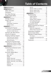
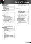
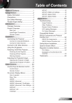
Table of Contents
Table of Contents
Important Information................................................................................................... 2
Table of Contents ........................................................................................................... 5
1. Overview of Software ................... 8
1-1.
Overview of DCC.......................................................................................... 8
1-1-1. Operating environment of PC version DCC ..............................................................8
1-2.
DCC installation/version upgrading ............................................................ 9
1-2-1. DCC (touch panel) version upgrading .....................................................................9
1-2-2. PC version DCC installation/version upgrading ......................................................10
1-2-3. PC version DCC uninstalling ................................................................................10
1-3.
Activation and termination of DCC ............................................................ 11
1-3-1. Activation and termination of DCC (touch panel) ...................................................11
1-3-2. Activation and termination of PC version DCC .......................................................12
1-4.
Setting a connection destination............................................................... 13
2. Setting Up Your Projector ......... 15
2-1.
Following Setup......................................................................................... 15
2-2.
Adjusting Colors ........................................................................................ 16
2-2-1. Changing the Control Mode to Installation Mode....................................................16
2-2-2. Creating "MCGD" Data........................................................................................17
2-2-3. Projecting Red, Green, Blue, and White Colors ......................................................20
2-3.
Adjusting the Lens Setup and Lamp Brightness........................................ 21
2-3-1. Adjusting the Lens .............................................................................................21
2-3-2. Adjusting the Brightness of the Lamp...................................................................22
2-4.
Registering Titles ...................................................................................... 23
2-4-1. Information on Default Titles...............................................................................23
2-4-2. Overview of Titles ..............................................................................................28
2-4-3. Displaying TITLE Screen .....................................................................................29
2-4-4. Creating New Titles ............................................................................................30
2-4-5. Editing a Title ....................................................................................................34
2-4-6. Deleting a Title ..................................................................................................35
2-4-7. Registering a Test Pattern for a Title.....................................................................35
2-5.
Creating a PCF File .................................................................................... 37
2-5-1. Overview of PCF File...........................................................................................37
2-5-2. Creating a New PCF File......................................................................................37
2-6.
Creating a SCREEN File.............................................................................. 42
2-6-1. Overview of SCREEN files....................................................................................42
5
Table of Contents
2-6-2. Creating a New SCREEN File ...............................................................................42
3. Menu Functions [For projector operation] .... 46
3-1.
Project Operation Menu List...................................................................... 47
3-2.
START Screen ............................................................................................ 49
3-1-1. List of Menu Items of the Tool bar........................................................................48
3-2-1. Changing the menu mode...................................................................................50
3-3.
MAIN Screen ............................................................................................. 51
3-4.
LENS Screen .............................................................................................. 57
3-5.
LAMP Screen ............................................................................................. 59
3-3-1. Configuring the Preset Buttons ............................................................................55
3-5-1. LAMP Screen (Adjust).........................................................................................59
3-5-2. LAMP Screen (Information) .................................................................................61
3-5-3. LAMP Screen (Setup) .........................................................................................62
3-6.
STATUS Screen.......................................................................................... 64
3-7.
TITLE Screen ............................................................................................. 65
3-7-1. Title Advanced Screen ........................................................................................68
3-7-2. PCF Setting Screen ............................................................................................69
3-7-3. SCREEN Setting Screen ......................................................................................72
3-7-4. 3D Controls Screen ............................................................................................73
3-8.
INFO Screen .............................................................................................. 74
3-8-1. INFO Screen (Status) .........................................................................................75
3-8-2. INFO Screen (Status2) .......................................................................................78
3-8-3. INFO Screen (Log) .............................................................................................79
3-8-4. INFO Screen (SIB) .............................................................................................89
3-9.
SETUP Screen ............................................................................................ 91
3-9-1. SETUP Screen (Setup)........................................................................................91
3-9-2. SETUP Screen (Installation) ................................................................................95
3-9-3. SETUP Screen (Color Setting)..............................................................................98
3-9-4. SETUP Screen (MMS Setting) ..............................................................................99
3-9-5. SETUP Screen (Option Slot) .............................................................................. 100
3-10. LAN Screen.............................................................................................. 101
3-10-1. LAN Screen (IP Address)................................................................................... 102
3-10-2. LAN Screen (Mail) ............................................................................................ 103
3-10-3. LAN Screen (SNMP) ......................................................................................... 104
3-11. UPDATE Screen ....................................................................................... 106
3-11-1. Backing Up and Restoring Setting Information .................................................... 108
3-11-2. Comparing Cinema Files ................................................................................... 109
3-11-3. Setting the Setup Date of the Projector .............................................................. 110
3-11-4. Checking Log Files Using the Information Viewer................................................. 111
3-11-5. Checking the Version Information ...................................................................... 113
3-11-6. Updating the Firmware ..................................................................................... 115
6
Table of Contents
3-11-7. Macro File Tools ............................................................................................... 116
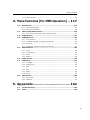
4. Menu Functions [For MMS Operation] .. 117
4-1.
Basic Screen ............................................................................................ 117
4-1-1. Menu Bar Explanation....................................................................................... 118
4-1-2. Status Bar Explanation ..................................................................................... 118
4-2.
Table of adjustment menus..................................................................... 119
4-3.
START Screen .......................................................................................... 122
4-4.
SOURCE Screen ....................................................................................... 123
4-2-1. Using the Service Personnel Menu (Mode switching) ............................................ 121
4-4-1. Input Terminal ................................................................................................. 124
4-4-2. Test Pattern [Support of upgrading is planned].................................................... 124
4-4-3. Entry List ........................................................................................................ 125
4-4-4. Default List [Support of upgrading is planned]................................................... 134
4-5.
ADJUST Screen........................................................................................ 135
4-5-1. Picture ............................................................................................................ 136
4-5-2. Input Settings ................................................................................................. 137
4-5-3. Resize............................................................................................................. 142
4-5-4. Options........................................................................................................... 146
4-6.
SETUP Screen .......................................................................................... 149
4-7.
LAN Screen.............................................................................................. 153
4-7-1. IP Address ...................................................................................................... 154
4-7-2. Network Type .................................................................................................. 155
4-7-3. WEP ............................................................................................................... 156
4-7-4. Mail ................................................................................................................ 157
4-7-5. DHCP.............................................................................................................. 158
4-7-6. Status............................................................................................................. 159
4-8.
INFO Screen ............................................................................................ 160
4-8-1. Source Info. .................................................................................................... 160
4-8-2. MMS Info. ....................................................................................................... 161
5. Appendix................................... 162
5-1.
Trouble Shooting..................................................................................... 162
5-2.
Index....................................................................................................... 163
7
1.
Overview
1-1. Overview of DCC
DCC is the software that is pre-installed in the touch panel. By using DCC, you can operate
NC
Series projectors and MM2000/MM2000B(*).
The PC version DCC that can be operated in the same way as DCC without a touch panel is also
available. By installing PC version DCC in the personal computer that is connected to a projector
in the LAN connection, DCC can be operated from the personal computer also.
(*) By using PC version DCC, you can operate MM2000/MM2000B. MM2000/MM2000B cannot
be connected from the touch panel DCC
1-1-1.
Operating environment of PC version DCC
This software can be used with the personal computer that fills the following environments.
Supported OS
Windows Vista, Windows XP, Windows 2003 Server, Windows 2000 Professional
Supported hardware
IBM PC/AT compatible personal computers
CPU
Pentium 300 MHz or higher required
Memory
128 MB or more
Network
TCP/IP-compatible LAN environment required
environment
8
1. Overview of Software
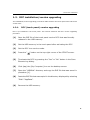
1-2. DCC installation/version upgrading
The installation/version upgrading procedures differ between the touch panel DCC and the PC
version DCC.
1-2-1.
DCC (touch panel) version upgrading
DCC is pre-installed in the touch panel. This section describes the DCC version upgrading
procedure.
[1]
Save the EXE file of the touch panel version DCC that was formally
released in the USB memory.
[2]
Set the USB memory in the touch panel after activating the DCC.
[3]
Set the DCC to a service mode.
[4]
Press the “
[5]
Terminate the DCC by pressing the “Yes” or “No” button in the Save
Execute Log dialog.
[6]
Click (tap) the [My Computer] icon on the desktop screen.
[7]
Open the “USBDisk” directory and copy the EXE file that was saved in
procedure [1].
[8]
Paste the EXE file that was copied in the directory displayed by selecting
“Disk”-“AppData”.
[9]
Remove the USB memory.
” button on the top-right corner of the START screen.
9
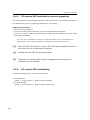
1. Overview of Software
1-2-2.
PC version DCC installation/version upgrading
This section describes the installation procedure of PC version DCC. Use the same procedure as
for installation for version upgrading (installation by overwriting).
Preparatory operation:
- Boot up your PC's Windows.
- If you have already started Windows, quit all running application programs.
If you do not quit all running programs before installing the DCC Software, you risk having
unsuccessful installation.
You must have "Administrators" privileges to install and uninstall the PC Control Software in
Windows 2000, and "Computer Administrators" privileges to do the same in Windows XP.
[1]
Save the EXE file of the PC version DCC that was released formally in
the local drive of the personal computer.
[2]
Double-click the EXE file that was saved.
[3]
Install the PC version DCC (version upgrading) according to the
instruction of the installer.
1-2-3.
PC version DCC uninstalling
Uninstall the Software from the menu shown below.
- For Windows XP
[Start] -> [Control Panel] -> [Add or Delete Program]
- For Windows 2000
[Start] -> [Control Panel] -> [Add or Delete Applications]
10
1. Overview of Software
1-3. Activation and termination of DCC
The activation method and termination method differ between the touch panel DCC and the PC
version DCC.
- Activation and termination of the touch panel DCC
:See 1-3-1 section (this page).
- Activation and termination of the PC version DCC
:See 1-3-2 section (next page).
When the DCC is initially activated first, the
“Language Select” screen appears. In this case,
select the display language.
In the following cases, the language selection
screen is not displayed since Chinese display is not
supported.
- Your touch panel is the NC-TP6401.
- You use the PC version DCC and the
Chinese font is not installed in your
personal computer.
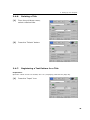
1-3-1.
Activation and termination of DCC (touch panel)
The touch panel power works together with the projector. When you turn on the main power to
your projector, it enters standby mode and the software automatically starts. Turning off the
main power to the projector causes the software to automatically exit.
11
1. Overview of Software
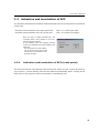
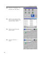
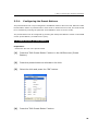
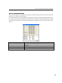
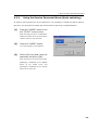
1-3-2.
Activation and termination of PC version DCC
Activate the PC version DCC.
The connection destination of the PC version DCC must be specified in advance on the
Communication Settings screen that is displayed at activation.
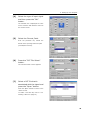
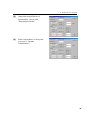
[1]
From the [Start] menu of Windows,
click [All the programs] → [Projector
User Supportware]→[Digital Cinema
Communicator(DCC)] in that order.
The Communication Settings screen is
displayed.
For the details of the Communication
Settings screen, see “3-4. Setting a
connection destination” (page 38).
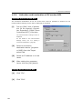
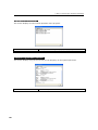
[2]
Select a connection
destination device (projector
or MMS) from the Target
select field.
[3]
Select an IP address or a host
name.
[4]
After setting the necessary
items, click the [OK] button.
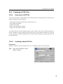
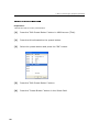
Exiting the PC version DCC.
12
[1]
Click “File”.
[1]
Click “Exit”.
1. Overview of Software
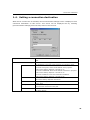
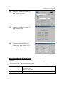
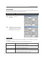
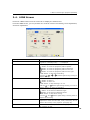
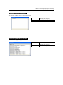
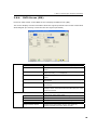
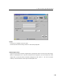
1-4. Setting a connection destination
When the PC version DCC is activated, the Communication Settings screen is displayed. Set a
connection destination on this screen. This screen can be displayed also by selecting
[Communication Settings] from the Setup menu of the tool bar.
Target Select
Select a device of the connection destination. Select Projector or
MMS.
Communication Device Settings
Enter the network setting of the connection destination device. Select
the IP address or the host name and enter the necessary items.
IP Address
Enter the IP address.
● Connect to Projector: Enter the IP address of the projector.
Value set at factory shipment: 192.168.10.10
● Connect to MM2000B: Enter the IP address of the built-in projector.
Value set at factory shipment: 192.168.10.10
● Connect to MM2000: Enter the IP address of MM2000.
Value set at factory shipment: 192.168.10.20
Host Name
Enter a host name of the device of the connection destination.
Value set at factory shipment: NC-Series
Port
Normally, no change is necessary.
Value: 7142
History button
Displays the History screen that shows the connection destinations
Search button
Displays the Search screen that searches connection destinations on
that have been connected in the past.
the same network.
13
1. Overview of Software
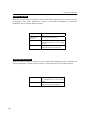
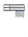
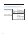
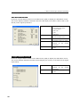
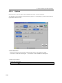
History screen
When the “History” button is pressed on the Communication Settings screen, the History screen
is displayed. This screen displays the history of connection destinations. A connection
destination can be selected from the history.
“Delete” button
Deletes the history selected in the
list.
“All Delete”
Deletes the entire history.
button
“OK” button
Enter the connection destination of
the selected history in the setting
screen.
“Cancel” button
Returns to the Communication Settings
without performing any processing.
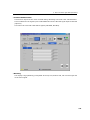
Search List screen
When the “Search” button is pressed on the Communication Settings screen, the Search List
screen is displayed. Use this screen to search a connection device on the same network.
“OK” button
Enter the connection destination of
the selected device in the setting
screen.
“Cancel” button
Returns to the Communication Settings
without performing any processing.
14
2.
Setting Up the
Projector
This chapter describes how to initialize the projector using the touch panel
2-1. Following Setup
●STEP1
Adjusting Colors
●STEP2
Creating "MCGD" Data
●STEP3
Adjusting the color tone of the test pattern
●STEP4
Adjusting the Lens and the Brightness of the Lamp
●STEP5
Creating New Titles
15
2. Setting Up Your Projector
2-2. Adjusting Colors
This corrects the chromaticity of the colors of the image projected on the screen by means of a
color meter and performs the setting of target colors (TCGD) during test pattern projections.
You can also project an image in target colors (TCGD file) with red, green, blue and white colors
selected.
The projector measures the value of each native color (color before corrections) and saves it in
a file (MCGD) to allow the user to faithfully reproduce the specified color (i.e., target color or
TCGD).
Initial Preparation
- Use a colorimeter to make preparations so that the value of the screen center can be
measured.
- Display the “Cross Hatch” test pattern to adjust the screen center.
- Set the brightness of the room to projection conditions (i.e., turn off all illumination).
- Use of a PR-650 manufactured by PHOTO RESEARCH is recommended in measurement of the
chromaticity level.
- Adjust the alignment of the valve prior to measuring the MCGD.
- Wait at least 15 minutes for the projector to warm up and the brightness becomes constant
before adjusting alignments.
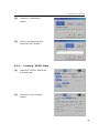
2-2-1.
Changing the Control Mode to Installation Mode
To perform advanced adjustments, you need to select the Installation (or Service) mode.
Color adjustment is not available in the User mode.
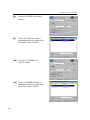
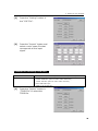
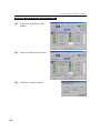
[1]
Press the “MODE” button from
the “START” menu screen.
The
Mode"
appears.
16
"Control
screen
2. Setting Up Your Projector
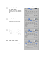
[2]
Press the “Installation”
button.
[3]
Enter your passcode and
press the “OK” button.
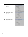
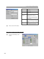
2-2-2.
Creating "MCGD" Data
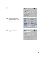
[1]
Press the “SETUP” button on
the menu bar.
[2]
Press the "Color Setting"
button.
17
2. Setting Up Your Projector
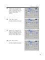
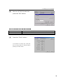
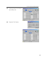
[3]
Press the “Create” button in
the “MCGD Setup”.
The "Red", "Green", "Blue", and "White"
buttons within MCGD Setup will become
valid.
[4]
Press “Red” button.
There will be projection to the screen in
the native color (red) of the projector.
[5]
Measure the chromaticity [x,
y] of the screen center, then
enter the measured value into
the [x] section and the [y]
section located under [Red].
[6]
Press “Green” button.
There will be projection to the screen in
the native color (Green) of the projector.
18
2. Setting Up Your Projector
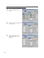
[7]
Measure the chromaticity [x,
y] of the screen center, then
enter the measured value into
the [x] section and the [y]
section located under
[Green].
[8]
Press “Blue” button.
There will be projection to the screen in
the native color (Blue) of the projector.
[9]
Measure the chromaticity [x,
y] of the screen center, then
enter the measured value into
the [x] section and the [y]
section located under [Blue].
[10] Press “White” button.
There will be projection to the screen in
the native color (White) of the projector.
19
2. Setting Up Your Projector
[11] Measure the chromaticity [x,
y] of the screen center, then
enter the measured value into
the [x] section and the [y]
section located under [White].
[12] Save the settings.
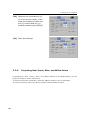
2-2-3.
Projecting Red, Green, Blue, and White Colors
By pressing the "Red", "Green", "Blue", and "White" buttons in the “MCGD Setup”, you can
project an image in colors, respectively.
To select a target color (TCGD file), press the “SELECT” button in the “TCGD Setup”.
You can also select a native color of the projector with the “Native” button.
20
2. Setting Up Your Projector
2-3. Adjusting the Lens Setup and Lamp Brightness
You can register adjusted lens settings (lens memory function) or adjusted brightness of the
lamp (lamp memory function). Assign registered settings to titles to call them up later. For
information on the lens and lamp memory functions, refer to the NC-TP6402/NC-TP6401 Touch
Panel Controller User's Guide.
2-3-1.
Adjusting the Lens
The projector zoom, focus and projected screen (lens shift) are adjusted with the “LENS” screen
for information on how to adjust them, refer to the NC-TP6402/NC-TP6401 Touch Panel
Controller User's Manual.
When the projector main unit is used in the NC1600 Series, the following functions cannot be used.
- Copy of the Lens Memory function ([Copy] button on the Lens Memory screen)
- Paste of the Lens Memory function ([Paste] button on the Lens Memory screen)
- With Focus of the Lens Memory function (With Focus check box of the Lens Memory Setup field
of the Lens Memory screen)
21
2. Setting Up Your Projector
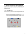
2-3-2.
Adjusting the Brightness of the Lamp
The brightness of the lamp is adjusted using the LAMP screen. For information on how to adjust
it, refer to the NC-TP6402/NC-TP6401 Touch Panel Controller User's Guide.
Setting FeedBack to “Enable” allows the set brightness to be maintained automatically.
In the case of movies, adjust the brightness of your DLP Cinema Projector to approximately 12
or 14 (ftl).
The set value will be invalidated after replacement of the lamp, therefore, you must set lamp
brightness once again.
If you set 100% of the lamp output, automatic brightness adjustment (FeedBack mode) will be
disabled.
22
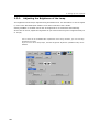
2. Setting Up Your Projector
2-4. Registering Titles
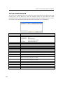
2-4-1.
Information on Default Titles
The data listed below have been cataloged in your projector before shipping from our factory.
When projecting an image source covered by these data, you do not need to change the
settings of your projector. When projecting an image source other than those mentioned above
(data listed below), follow the procedures given in Section, “2-4-4. Creating New Titles” (Page.
30) Title Creation and Editing" and subsequent sections.
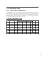
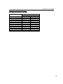
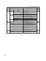
List of Default Titles (NC2000c )
Macro
Key No.
TITLE
Input
FILES
source
PCF
SCREEN
active
TCGD
aspect
Anamorphic Lens
1
CS-SCOPE1920
SDI-A
CS-SCOPE
1920x1080
Anamo1.25
SCOPE
1920x1080
2.35
P7v2
theatre
1.25
2
VV-FLAT 1920
SDI-B
VV-FLAT
1920x1080
DC2K VISTA
1920x1080
1.85
P7v2
theatre
none
3
HDTV
SDI-A
HDTV
1920x1080
DC2K HDTV
1920x1080
0
Rec 709
none
4
SDI-DUAL-RGB
SDI-A,B
SDI DUAL RGB
1920x1080
2048x1080 No 1920x1080
Crop
0
P7v2
theatre
none
5
DVI-A
DVI-A
DVI 2048x1080
DC2K DVI
2048x1080
0
P7v2
theatre
none
6
DVI-B
DVI-B
DVI 2048x1080
DC2K DVI
2048x1080
0
P7v2
theatre
none
7
DVI-TWIN
DVI-A,B
DVI 2048x1080
DC2K DVI
2048x1080
0
P7v2
theatre
none
List of Default Titles (NC1600 series)
23
2. Setting Up Your Projector
NOTES:
24
2. Setting Up Your Projector
NOTES:
25
2. Setting Up Your Projector
List of Default SCREENs
SCREEN FILE NAME
Anamo125 SCOPE.SCREEN
DC2K SCOPE.SCREEN
DC2K DUAL.SCREEN
DC2K DVI.SCREEN
DC2K HDTV AREA.SCREEN
DC2K HDTV.SCREEN
DC2K SXGA AREA.SCREEN
DC2K VISTA AREA.SCREEN
DC2K VISTA.SCREEN
1280x1024 No Crop.SCREEN
1400x1050 No Crop.SCREEN
2048x1080 No Crop.SCREEN
26
anamorphic factor
1.25
1
1
1
1
1
1
1
1
1
1
1
screen presentation
2048x1080
2048x1080
2048x1080
2048x1080
1920x1080
2048x1080
1280x1024
1998x1080
2048x1080
1280x1024
1400x1050
2048x1080
2. Setting Up Your Projector
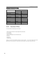
List of Default SOURCEs
SOURCE FILE NAME
1280x1024 SCOPE.SOURCE
1920x817 SCOPE.SOURCE
1920x1024 SCOPE.SOURCE
1920x1080 SCOPE.SOURCE
2048x1080 SCOPE.SOURCE
1280x1024 VISTA.SOURCE
1920x1024 VISTA.SOURCE
1920x1038 VISTA.SOURCE
1920x1080 VISTA.SOURCE
2048x1080 VISTA.SOURCE
1280x1024 HDTV.SOURCE
1920x1024 HDTV.SOURCE
1920x1080 HDTV.SOURCE
2048x1080 HDTV.SOURCE
source
active
1280x1024
1920x817
1920x1024
1920x1080
2048x1080
1280x1024
1920x1024
1920x1038
1920x1080
2048x1080
1280x1024
1920x1024
1920x1080
2048x1080
aspect
2.35
0
2.35
2.35
2.35
1.85
1.85
0
1.85
1.85
1.778
1.778
0
1.778
27
2. Setting Up Your Projector
List of Default SOURCEs
SOURCE FILE NAME
source
active
aspect
1280x1024 1778
1280x1024
1.778
1280x1024 185
1280x1024
1.85
1280x1024 235
1280x1024
2.35
1280x1024 Square Pixels
1280x1024
1.25
1800x1080 1667
1800x1080
1.667
1920x1038 185
1920x1038
1.85
1920x1080 1778
1920x1080
1.778
1920x803 239
1920x803
2.39
1920x817 235
1920x817
2.35
2048x1024 Square Pixels
2048x1024
2
2048x1080 Square Pixels
2048x1080
1.896
2048x857 239
2048x857
2.39
2048x871 235
2048x871
2.35
Auto Square Pixels
0x0
0
2-4-2.
Overview of Titles
You can preset the followings for each title.
- Select Signal (selection of input signal and signal type)
- Lens memory
- Lamp memory
- Setup of anamorphic lens motorized turret
- PCF files
- MCGD files
- SCREEN files
Calling up a preset title facilitates switching of input signals. You can also assign titles to the
Macro keys on the projector's control panel and call them up directly using these keys.
28
2. Setting Up Your Projector
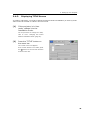
2-4-3.
Displaying TITLE Screen
To create or edit a title, you need to change the Control Mode to Installation (or Service) mode.
Titles cannot be created or edited in the User mode.
[1]
If the projector is in User
mode, change it to the
Installation mode.
For the procedure to change the mode,
refer to “2-2-1. Changing the Control
Mode to Installation Mode” (page 16).
[2]
Press the “TITLE” button on
the menu bar.
The “TITLE” screen will appears.
If the "TITLE” button is not visible, press
the “
” button on the menu bar and then
scroll the menu bar.
29
2. Setting Up Your Projector
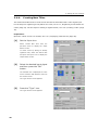
2-4-4.
Creating New Titles
This section describes how to create a new title that is associated with a video signal input.
For the steps for registering a test pattern for a title, see 2-4-7, Registering a Test Pattern for
a Title (Page 35). For the steps for editing a registered title, see “2-4-5, Editing a Title” (Page
34).
Preparation:
Open the "TITLE" screen. For details, see 2-4-3, Displaying TITLE Screen (Page 29).
[1]
Set the Input icon.
Select
“Create
New
Title”
from
the
pull-down menu to display the “Input
Select” screen.
To create a title by editing an already
registered title, select the desired title
and press the Input icon to display the
“Input Select” screen.
[2]
Select the desired input signal
and then press the “OK”
button.
The selected icon is displayed as a blue
cursor. Press the “OK” button to return to
the “TITLE” screen.
The "Type Select" screen appears.
[3]
Press the “Type” icon.
The "Type Select" screen appears.
30
2. Setting Up Your Projector
[4]
Select the type of input signal
and then press the “OK”
button.
The selected icon is displayed as a blue
cursor. Press the “OK” button to return to
the “TITLE” screen.
[5]
Select the Format, Path.
From the pull-down list, selects the
format of the input signal and the path
(Cinema/Non-Cinema).
[6]
Press the “PCF File Select”
button.
The “PCF File Select” screen appears.
[7]
Select a PCF file that is
associated with the signal and
press the “Open” button.
Press the “Open” button to return to the
“TITLE” screen.
To create a new PCF file, refer to “2-5.
Creating a PCF File” (Page 37).
31
2. Setting Up Your Projector
[8]
Press the “MCGD File Select”
button.
[9]
Select an MCGD file that is
associated with the signal and
press the “Open” button.
[10] Press the “SCREEN File
Select” button.
[11] Select a SCREEN file that is
associated with the signal and
press the “Open” button.
32
2. Setting Up Your Projector
[12] Press the "Advanced” button.
[13] Configure the advanced
settings depending on the
input signal and press the
"Exit" button.
[14] Press the "Store As ..."
button.
33
2. Setting Up Your Projector
2-4-5.
Editing a Title
Preparation:
Open the "TITLE" screen. For details, see 2-4-3, Displaying TITLE Screen (Page 29).
34
[1]
From the pull-down menu,
select a desired title.
[2]
Edit the settings.
[3]
Press the "Store As ..."
button.
2. Setting Up Your Projector
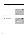
2-4-6.
Deleting a Title
[1]
From the pull-down menu,
select a desired title.
[2]
Press the "Delete" button.
2-4-7.
Registering a Test Pattern for a Title
Preparation:
Open the "TITLE" screen. For details, see 2-4-3, Displaying TITLE Screen (Page 29).
[1]
Press the "Input" icon.
35
2. Setting Up Your Projector
36
[2]
Select the "Test Pattern" icon
and press the "OK" button.
[3]
Select the test pattern (TGA
File) you want to register and
press the "Open" button.
[4]
Select the type of the test
pattern signal.
[5]
Press the "Store As ..."
button.
2. Setting Up Your Projector
2-5. Creating a PCF File
2-5-1.
Overview of PCF File
The PCF file (Projector Configuration File) includes the items mentioned below, which are the
setting information of the projector.
- Input signal information (Resolution, aspect ratio, etc.)
- Color Space information
- Gamma information
- Native color information (MCGD)
- Target color information (TCGD)
To create a PCF file, use the "Setting" button on the "TITLE" screen. One creation method is to
call an existing file, make changes, and then save the file, and another method is to create a
new file; however, the basic operations are the same and the method of creating a new file will
be described here
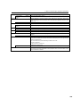
2-5-2.
Creating a New PCF File
Preparation:
Open the "TITLE" screen. For details, see 2-4-3., Displaying TITLE Screen (Page 29).
[1]
From the pull-down menu,
select a signal.
37
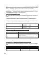
2. Setting Up Your Projector
[2]
Press the “Setting” button in
the “PCF File Select”
[3]
Press the “Setting” button in
the SOURCE File.
[4]
Enter the Aspect Ratio and
Input Size, then press "EXIT"
button.
Example of setting SOURCE File
Conditions:
- Screen sizes
:Project the screen size in Vista (Aspect ratio is 1:1.85)
- Input signal format: HD-SDI 1920x1080@24psF
Squeeze signals
(Signals that have been compressed at the control side 1920 to 1280 in the
horizontal direction and 1080 to 1024 in the vertical direction)
Aspect Ratio :1.85
Input Size :1280x1024
38
For signals other than
Aspect Ratio :1.85
squeeze signals
Input Size :1920x1080
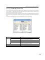
2. Setting Up Your Projector
[1]
Press the “Setting” button in
the “CSC File”.
[2]
Press the "Import" button and
select a color space file that
corresponds to the input
signal.
Example of selecting a CSC file:
For DVI connector
-RGB input: "Unity RGB.CSC" (same as "Mk7 Unity RGB.CSC")
For HD-SDI connector
- Component input:10-bit 64-940.CSC"
"YCbCr 240M.CSC" (same as "Mk7 YCbCr 240M.CSC")
"YCbCr 709.CSC" (same as "Mk7 YCbCr 709.CSC")
- DUAL LINK RGB input:
"RGB 10-bit 64-940.CSC"
[1]
Press the "Import" button in
"TCGD File" to select the
TCGD file.
39
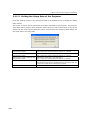
2. Setting Up Your Projector
40
[2]
Press the "Import" button in
"LUT-AL File" to select the
LUT-AL file.
[3]
Press the "Import" button in
"LUT-CLUT File" to select the
LUT-CLUT file.
[4]
Press the "Setting" button in
"LUT-DG File".
2. Setting Up Your Projector
[5]
Set the LUT-DG file and then
press the "OK" button.
Example of setting LUT-DG File
Movies
"Gamma 2.6.LUT-DG" (equivalent to "Mk7 PL2.6.LUT-DG)
PC and Other Input
"Graphics_Enhanced.LUT-DG
When using Parametric
Select "Parametric" to enter the degamma value.
[1]
Press the "Save" button.
To overwrite an existing file, check that
the file being edited is selected before
pressing the "OK" button.
41
2. Setting Up Your Projector
2-6. Creating a SCREEN File
2-6-1.
Overview of SCREEN files
SCREEN files includes the items mentioned below, which are the setting information of the
projector.
- display area information
- Anamorphic Lens information
- Crop information
To create a SCREEN file, use the "Setting" button on the "TITLE" screen. One creation method
is to call an existing file, make changes, and then save the file, and another method is to create
a new file; however, the basic operations are the same and the method of creating a new file will
be described here.
For information on assigning a PCF file to a title, see 2-4-4, “Creating New Titles” (Page 30).
2-6-2.
Creating a New SCREEN File
Preparation:
Open the "TITLE" screen.
[1]
From the pull-down menu,
select a signal.
To create a SCREEN file, the current title
(the currently selected signal) needs to
be selected.
[2]
42
Press the "Setting" button on
the right-hand side of
"SCREEN File Select".
2. Setting Up Your Projector
[3]
Input the magnification of
Anamorphic Lens in the
“Anamorphic factor”
[4]
Enter information on the pixel
you use in "Screen
Presentation".
43
2. Setting Up Your Projector
SCREEN file
This sets the horizontal display area to be used when the primary lens zooming feature does not
meet the required projection in a fixed wide-screen format.
VISTA Screen
Call the DC2K VISTA AREA.SCREEN file.
HDTV Screen
Call the DC2K HDTV AREA.SCREEN file.
[1]
Select the "Letterbox"
checkbox.
[2]
"Cropping" is used when the
projected image is too large to
be displayed in the screen.
"Cropping"
Select the item you want to adjust the amount of cropping (x- and y-coordinate) or the amount
of curvature.
You can make adjustments using the scroll bar or entering numerical values.
Upper Left
Sets the amount of cropping at the upper left of the screen. (This becomes
the reference point of the XY coordinates.)
Left Curve
Sets the amount of curvature of the left vertical line of the screen.
Enter the value of the relative value from the x coordinates of Upper Left
and Lower Left. Setting this value to a negative value permits the correction
of the distortion of the anamorphic lens.
Lower Left
Sets the amount of cropping at the lower left of the screen
Top Curve
Sets the amount of curvature of the top horizontal line of the screen.
Enter the value of the relative value from the y coordinates of Upper Left
and Upper Right. Setting this value to a negative value permits the
correction of the distortion of the anamorphic lens.
44
2. Setting Up Your Projector
Bottom Curve
Sets the amount of curvature of the bottom horizontal line of the screen.
Enter the value of the relative value from the y coordinates of Lower Left
and Lower Right. Setting this value to a positive value permits the
correction of the distortion of the anamorphic lens.
Upper Right
Sets the amount of cropping at the upper right of the screen.
Right Curve
Sets the amount of curvature of the right vertical line of the screen.
Enter the value of the relative value from the x coordinates of Upper Right
and Lower Right. Setting this value to a positive value permits the
correction of the distortion of the anamorphic lens.
Lower Right
[1]
Sets the amount of cropping at the lower right of the screen.
Press the "Save" button.
45
3.
Menu Functions
This chapter describes the functions of the projector operation menus. See “4. Menu functions
[For MMS operation]” (page 117) for the menus for multimedia switcher (MMS) operation.
This is a screen example of the NC2000 Series.
46
3. Menu Functions [For projector operation]
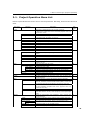
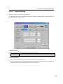
3-1. Project Operation Menu List
Menus in parentheses are menus for our service personnel. Normally, these menus cannot be
used.
Main menu
Submenu
START
POWER On/Off
Lamp
MODE
MAIN
Preset Button
Title
Test
Anamorphic Out/In
Douser Open/Close
(Edit Preset Button)
LENS
Fine-adjust Mode
Shift
Zoom
Focus
Lens Memory
Lens Mount Initialize
LAMP
Adjust
Lamp Output
Feedback
Lamp Memory
Information
(Setup)
STATUS
(TITLE)
INFO
Status
Status2
Log
SIB
(SETUP)
Setup
Installation
(Color Setting)
(TCGD Setup)
MMS Setting
Option Slot
Description
This screen is displayed when the controller is started.
It displays the model name of the connected projector main unit
and the DCC version.
To turn on and off the projector.
To turn on and off the lamp. Use this when you do not want to turn
on the light though the power is turned on.
To change the menu mode.
Select the input signal from this screen.
To display the titles assigned to the preset buttons*.
To display the title list registered in the projector.
To display the test pattern list.
To control the anamorphic lens.
To control the Douser function.
To set the titles to be assigned to the preset buttons*.
Control the lens from this screen.
Set to operate only while pressing the Lens Shift, Zoom, or Focus
buttons.
To shift the lens.
To zoom in and zoom out.
To adjust focus.
Edit titles and display for the lamp.
To reset the lens control system in an emergency. You should not
normally use this.
Control the lamp from this screen.
To adjust the lamp brightness.
To adjust the lamp output.
To set the lamp brightness constant mode that uses a brightness sensor.
To save the current lamp settings, and call the saved settings.
To display the lamp information.
Configures detailed lamp settings.
Projector setting status is displayed in this screen.
Set titles and display the list in this screen. This is used by the
service personnel.
Screen for display of various information about the projector.
To check version information and error information for the projector
main unit, ICP board, and multi media switcher (MMS). You can also
save the logs that have accumulated in the projector main unit.
To check the states of slot A and slot B in the projector main unit
and the installation complete date of the projector main unit
(warrantee start date).
To check the state of the projector main unit and the various logs.
To check the status and version information of the signal input
board itself and the security circuit (Enigma) on the signal input
board.
Screen for initial setting upon installation. This is used by the
service personnel.
Screen for configuring various settings of the projector main unit.
Screen for configuring settings upon installation.
Set a target color file (TCGD). This is a post production menu.
Ref.
page
49
51
57
59
64
65
74
91
Configures whether or not the MMS is used.
Screen for configuring the settings of slot A and slot B.
47
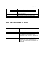
3. Menu Functions [For projector operation]
(LAN)
IP Address
Mail
SNMP
(UPDATE)
button
Shield button
Screen for LAN setting. This is used by the service personnel.
Screen for configuring the IP address.
Screen for configuring the email notification function settings.
Screen for configuring SNMP settings.
This screen is used to update various firmware and system data,
backup and restore projector settings files, view log files, etc. This is
used by the service personnel.
Buttons that switch pages for the main menu bar.
- Menu items for page 1: START, MAIN, LENS, LAMP, and STATUS
- Menu items for page 2: TITLE, INFO, SETUP, LAN and UPDATE
This button enables and disables the DCC button operations.
101
106
-
-
* Preset buttons 1 to 8 correspond to preset buttons 1 to 8 on the projector.
3-1-1.
List of Menu Items of the Tool bar
Menu
File
Submenu
Description
Exit
Terminates DCC.
Save Execute Log
This is only displayed while in Service mode.
The communication packets between the DCC and the target
projector can be captured and saved in a text format file.
Setup
Communication Setting
Displays the connection setting dialog. (See page 13)
Option
Always on Top
Select whether the DCC screen is always displayed as the first
screen. At activation, “Not display first” is selected.
Not checked: The DCC screen is not displayed in the
foreground.
Checked: The DCC screen is always displayed in the
foreground.
Disp Local Time
Sets the date and time for when logs are displayed using DCC.
Not checked: Uses universal coordinated time (UTC).
Checked: Uses the local time set in the projector main unit.
(See page 96)
48
3. Menu Functions [For projector operation]
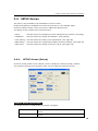
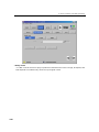
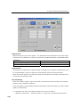
3-2. START Screen
When the soft is activated or when you pre ss the “START” button from the menu bar, the
START screen is displayed.
From the START screen, you can turn on and off (standby status) the projector, turn on and off
the lamp and change the menu mode.
System
Shows the model name of the projector.
Version
Displays the version of the software.
LAN
Displays the IP address of the target projector.
Power “On” button
Turns on and off (standby status) the power.
Power “Off” button
Lamp
Turns on and off the lamp. Use this when you do not want to turn on the light
though the power is turned on. If this button is set to “Off” in the standby
mode, you can turn on the power without tuning on the lamp.
“Disable Lamp On
Enables or disables turning on/off of the lamp immediately after switching
while cooling”
between On and Off for the lamp.
check box
- With check mark:
You cannot switch between On and Off of the lamp
for about 5 minutes after On/Off switching.
- Without check mark: You can turn on or off the lamp immediately after
On/Off switching.
Usually, use the system with a check mark in this check box.
“On” button
“Off” button
“MODE” button
Turn on the lamp.
Turn off the lamp.
This button changes the menu mode.
49
3. Menu Functions [For projector operation]
3-2-1.
Changing the menu mode
There are four menu modes available. The menu items that can be used differ depending on the
mode.
When you press “MODE” on the START screen, you can switch the menu mode. Dedicated
passcodes need to be entered in order to switch to any mode other than user mode.
User mode
Advanced User mode
Menu for usual operation. To display the basic menu items only.
Menu for replacement of the lamp. The lamp settings menu can be used in
addition to the menus that can be used in User mode.
Installation mode
Menu for installation.
Service mode
Menu for the service personnel.
Pospro mode
Menu for the post productions.
A menu item equivalent to the Service mode can be used and detail setup of a
target color file (TCGD) is enabled.
When the mode is changed from the User mode, the “MODE” button and the “Shield” button are
displayed as shown below.
50
- In Advanced User mode:
“MODE (A)”, “Shield (A)”
- In Installation mode:
“MODE (I)”, “Shield (I)”
- In Service mode:
“MODE (S)”, “Shield (S)”
- In Pospro mode:
“MODE (P)”, “Shield (P)”
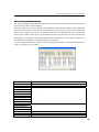
3. Menu Functions [For projector operation]
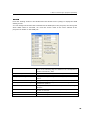
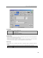
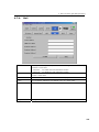
3-3. MAIN Screen
Press the “MAIN” button from the menu bar to display the MAIN screen.
The MAIN screen is used to select the signal to input to the projector, control the anamorphic
lens/wide converter lens, and control the douser. The input signal selection can be switched
between the following three types by pressing the button in the Select field.
- Preset Button:
Displays a list of the preset buttons registered in the projector main unit.
- Selects the title (input signal) registered in the preset button
- Sets the preset button
- Title:
Displays a list of the titles registered in the projector main unit.
- Selects the title to project
- Sets the preset button
- Test:
Displays a list of test patterns.
- Selects the test pattern to project
- Sets the test pattern
MAIN screen (Preset Button)
MAIN screen (Title)
MAIN screen (Test)
51
3. Menu Functions [For projector operation]
Select
Select the input signal.
“Preset Button” button
These buttons have the same function as macro keys 1-8 provided on
the control panel of the projector. Press the title buttons to select the
titles (input signals) assigned to the preset buttons 1-8.
“Title” button
- Title displayed in blue:
Title is selected.
- Title displayed grayed out:
The title cannot be selected.
To display the title list registered in the projector. From this screen,
you can select the title (input signal).
“Test” button
To display the test pattern list from this screen, you can select the
test pattern.
“Edit” button*
To go to the test pattern edit mode to change the registration of the
test pattern.
“Advanced” button*
Displays a detailed setting screen (Test Pattern Advanced) for the
currently selected test pattern. This button can only be used while a
test pattern is selected.
Anamorphic “Out” button
These buttons control the anamorphic lens/wide converter lens.
Anamorphic “In” button
- “Out” button:
To disable anamorphic lens/wide converter lens.
- “In” button:
To enable anamorphic lens/wide converter lens.
Douser “Open” button
The following buttons control the douser.
Douser “Close” button
- “Open” button: Cancels the douser function and let the projection
light go.
- “Close” button: Causes the douser to shut off the projection light.
“Edit Preset Button” button*
This button is used to edit the preset buttons. (See page 55)
This cannot be used while the MAIN screen (Test) is being displayed.
*
52
This menu is only available in the Installation or Service mode.
3. Menu Functions [For projector operation]
The icons displayed on the MAIN screen (Preset Button) and MAIN screen (Title) have the
following meanings.
Input icon
Shows the input signal terminal.
Input for SDI-A
Input for SDI-B
Dual input for SDI-A
terminals
terminals
and SDI-B terminals
Input for SDI-C
Input for SDI-D
Dual input for SDI-C
terminals
terminals
and SDI-D terminals
Quad input through
the SDI-A, SDI-B,
-
-
-
-
SDI-C, and SDI-D
ports (currently not
supported)
Input for DVI-A
Input for DVI-B
Dual/Twin input for
terminals
terminals
DVI-A and DVI-B
Input for the image
Multi media switcher
media block (IMB)
(MMS) input (TWIN
terminal
input)
terminals
Built-in test pattern
Type icon
Indicates a signal type.
SCOPE
FLAT
HDTV
SDTV
PC
TEST signal
Signal of
3D
Signal
Multi-media switcher
of
Image
media block (IMB)
(MMS)
If none is selected:
53
3. Menu Functions [For projector operation]
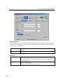
Test Pattern Advanced Screen
This screen can be displayed only when a test pattern is selected in Installation mode or Service
mode.
Press the “Advanced” button with the test pattern selected in the MAIN screen (Test) to display
the Test Pattern Advanced screen. Detailed settings of the test patterns are configured on this
screen.
Image Scaler
Turns on and off the image scaler of
On/Off
the selected test pattern.
SCREEN File
Sets the SCREEN file of the selected
Setting
test pattern.
Test Pattern
Set the MCGD file and the TCGD file of
Setting
the selected test pattern.
“Exit” button
Closes the Test Pattern Advanced
screen and returns to the MAIN screen.
54
3. Menu Functions [For projector operation]
3-3-1.
Configuring the Preset Buttons
The preset buttons can only be configured in Installation mode or Service mode. When the “Edit
Preset Button” button is pressed while in User mode or Advanced User mode, the mode needs
to be switched by entering the passcode for Installation mode or Service mode.
The preset buttons can be configured by pressing the “Edit preset Button” button on the MAIN
screen (Preset Button) or MAIN screen (Title).
For MAIN screen (Preset Button)
Preparation:
- Selects the title set in the preset button.
[1]
Press the “Edit Preset Button” button in the MAIN screen (Preset
Button).
[2]
Press the preset button to allocate to the title.
[3]
Select the title and press the “OK” button.
[4]
Press the “Edit Preset Button” button.
55
3. Menu Functions [For projector operation]
For MAIN screen (Title)
Preparation:
・Selects the title set in the preset button.
56
[1]
Press the “Edit Preset Button” button in MAIN screen (Title).
[1]
Press the title allocated to the preset button.
[2]
Select the preset button and press the “OK” button.
[3]
Press the “Edit Preset Button” button.
[4]
Press the “Preset Button” button in the Select field.
3. Menu Functions [For projector operation]
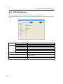
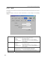
3-4. LENS Screen
Press the “LENS” button from the menu bar to display the LENS screen.
From the LENS screen, you can perform lens controls such as lens shifting, zoom adjustment,
and focus adjustment.
“Fine-adjust Mode” button
Lens Firmware Version
Press the “Fine-adjust Mode” button for fine adjustment.
Displays the firmware version of the lens mount. When the
projector is in standby mode, “---” is displayed.
Shift
Move the projection screen vertically and horizontally.
“ ” button: To move the projection position upward.
“ ” button: To move the projection position downward.
“ ” button: To move the projection position to the left.
“ ” button: To move the projection position to the right.
“STOP” button: To stop the lens shifting.
Press the “ ” “ ” “ ” or “ ” buttons again during moving to
stop the moving.
Zoom
Zoom in and zoom out the projection screen.
“ ” button: To zoom in.
“ ” button: To zoom out.
“STOP” button: To stop zooming in or out.
Press the “ ” or “ ” button again during zooming in or out to
stop the zoom-in or zoom-out operation.
Focus
Adjust the focus of the projection screen.
“ ” button: To set the focus distance longer.
“ ” button: To set the focus distance shorter.
“STOP” button: To stop focus moving.
Press the “ ” and “ ” button again during a moving focus to
stop the focus moving.
Lens Memory
The values after adjustment through the LENS screen
(Adjustment values for lens shift, zoom, and focus) can be
saved to the memory in the projector. (See page 58)
Lens Mount Initialize
Resets the lens control system in an emergency. You should
not normally use this.
57
3. Menu Functions [For projector operation]
Lens Memory Screen
Press the [Memory List] on the LENS window to display the Lens Memory window.
The values after adjustment through the LENS screen (Adjustment values for lens shift, zoom,
and focus) can be saved to the memory in the projector.
“Entry” button
Saves the current adjustment value
“Delete” button
Deletes the memory selected in the
“Test” button
Tests the adjustment value of the
“Copy” button
Copies the memory selected in the
to the memory.
list from the Lens Memory.
memory selected in the list.
list.
“Paste” button
Saves the copied memory and
overwrites the memory selected in
the list.
Len Memory Setup
Enables/disables
the
memory
selected in the list.
- Enable: Enables memory call-up.
- Disable: Disables memory call-up.
- With Focus: Apply a check mark
here to turn it on to also call up focus
adjustment values
(Only when the setting is "Enable").
“OK” button
Closes the Lens Memory window and
returns to the LENS window.
58
3. Menu Functions [For projector operation]
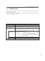
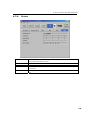
3-5. LAMP Screen
Press the “LAMP” button from the menu bar to go to the LAMP screen.
From the LAMP screen, you can adjust the lamp output and display the lamp information.
- Adjust
:To adjust the lamp brightness. (See This page)
- Information
:To display the lamp information. (See page 61)
- Setup
:To configure detailed lamp settings. (See page 62)
3-5-1.
LAMP Screen (Adjust)
Press the “Adjust” button on the LAMP screen to display the LAMP screen (Adjust).
The lamp output is adjusted using this screen.
Lamp Output
Displays the current lamp output. Press [ ]/[ ] button to adjust the
output. The output value can be adjusted by dragging the slide bar
between the [ ] and [ ] buttons.
If the lamp is off or the douser is closed, “Disabled by . . . (Lamp
Off/Douser Close/Lamp Off, Douser Close)” is displayed. When this
happens, the output value cannot be adjusted.
FeedBack
Sets the lamp brightness constant mode that uses a brightness
sensor. The box on the right side displays the operational status of
the Feedback function.
- Disable: Disables the lamp brightness constant mode (the color of
the box is gray).
- Enable: Enables the lamp brightness constant mode (the color of
the box is blue).
Lamp Memory
The lamp output values after adjustment through the LAMP screen
can be saved to the memory in the projector. Press the “Memory List”
button to display Lamp Memory screen. (See page 60)
59
3. Menu Functions [For projector operation]
Lamp Memory Screen
Press the [Memory List] on the LAMP window (Adjust) to display the Lamp Memory window.
The lamp output values after adjustment through the LAMP screen can be saved to the memory
in the projector.
“Entry” button
Saves the current lamp output
“Delete” button
Deletes the memory selected in the
value to the memory.
list from the Lens Memory.
“Test” button
Tests the adjustment value of the
memory selected in the list.
“Copy” button
Copies the memory selected in the
list.
“Paste” button
Saves the copied memory and
overwrites the memory selected in
the list.
“OK” button
Closes the Lamp Memory window
and returns to the LAMP window.
60
3. Menu Functions [For projector operation]
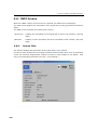
3-5-2.
LAMP Screen (Information)
Press the “Information” button on the LAMP screen to display the LAMP screen (Information).
You can check the current lamp type and output, the lamp bulb information and the bulb and
lamp house utilization hours on this screen.
Lamp PS Type
Displays the type of lamp.
Lamp PS Version
Displays the version information of the lamp.
Product Model
Product Number
Hard Version
Soft Version
Lamp Bulb
Displays the version information of the lamp bulb.
Name
Displays the product name of the lamp bulb.
Min Current
Displays the minimum current setting value (A) of the lamp
Max Current
Displays the maximum current setting value (A) of the lamp
bulb.
bulb.
Typical Watt
Displays the rated output of the lamp bulb.
Max Watt
Displays the maximum output of the lamp bulb (kW).
Warning Time
Output
Douser Count
Displays the warning time setting value of the lamp bulb.
Displays the output value of the lamp.
Displays the number of times the douser has been opened and
closed.
Usage
Displays the usage time of the lamp bulb, lamp house, and
cooling fan.
Warning
Displays the usage warning time of the lamp bulb and lamp
house.
61
3. Menu Functions [For projector operation]
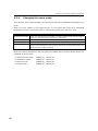
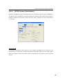
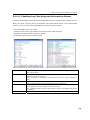
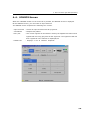
3-5-3.
LAMP Screen (Setup)
This menu is only available in the Installation or Service mode.
Press the “Setup” button on the LAMP screen to display the LAMP screen (Setup). On the LAMP
screen (Setup), you can register and change the lamp bulb, display the bulb alignment value,
set the bulb alarm time and the usage mode of the lamp house, etc.
New Bulb
Selects or edits a new entry of the lamp bulb (available in standby
status only). Press the “Entry List” button to display the "Bulb Entry"
screen. (See page 63)
New Lamp House
Press the “Usage Clear” button to clear the lamp house utilization
hours (available in standby status only).
Bulb Alignment
This sets the lamp bulb alignment value. Press the “Execute” button
to display the "Bulb Alignment” screen.
Bulb Warning
This sets the lamp bulb alarm time (available in standby status only).
- Use Bulb Entry: uses the time set by the Bulb Entry screen.
- Manual: Uses the value set manually.
For manual setting, input the time and press the “Apply” button.
Setting is available from 0 to 9999H.
House Usage Mode
This sets the lamp house usage mode (available in standby status
only).
- Single: To use the lamp house in the single mode
- MultiLamp House 1: To use the lamp house in multiple mode and
select the lamp house 1
- MultiLamp House 2: To use the lamp house in multiple mode and
select the lamp house 2
Douser Count
The number of times the douser has been opened and closed is
cleared by pressing the “Clear” button.
62
3. Menu Functions [For projector operation]
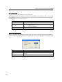
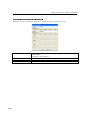
Bulb Entry Screen
Press the “Entry List” button in the LAMP screen (Setup) to display the "Bulb Entry" screen.
You can select or edit a new entry of the lamp bulb on this screen.
“Edit” button
Edits the entry selected in the
“Delete” button
Deletes the entry selected in the
list.
list from the Bulb Entry.
“Select” button
Sets the entry selected in the list
to the active status.
“Exit” button
Closes the Bulb Entry screen and
returns to the LAMP screen.
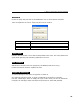
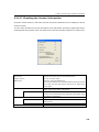
Bulb Alignment Screen
Press the “Execute” button in the LAMP screen (Setup - Bulb Alignment) to display the "Bulb
Alignment" screen. This screen is used when adjusting the lamp bulb shaft.
Peakhold
Displays the peak value.
Average
Displays the average.
“Peakhold Reset”
Resets the peak value.
button
“Exit” button
Closes the Bulb Alignment
screen and returns to the LAMP
screen.
63
3. Menu Functions [For projector operation]
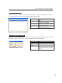
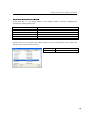
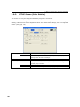
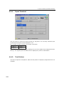
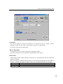
3-6. STATUS Screen
Press the “STATUS” button from the menu bar to go to the STATUS screen.
From the STATUS screen, you can check the input signal information and the Projector setting
status.
Input Signal
Active Files
Port
Displays the terminal of input signal.
Type
Displays the type of input signal.
PCF
Displays the name of PCF file selected.
SCREEN
Displays the name of SCREEN file selected.
3D
Displays the name of 3D file selected.
Active
Displays the resolution.
Aspect
Displays the aspect ratio.
Anamorphic factor
Sub Title
Anamorphic
Displays the anamorphic factor.
Indicates whether to use subtitles (currently not supported).
Displays the status of anamorphic lens/wide converter lens
control (Out/In).
64
Lamp
Displays the status of lamp output control (On/Off).
Douser
Displays the status of douser control (Open/Close).
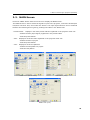
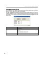
3. Menu Functions [For projector operation]
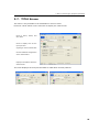
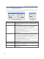
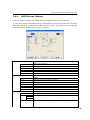
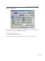
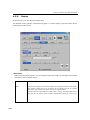
3-7. TITLE Screen
This menu is only available in the Installation or Service mode.
Press the "TITLE" button on the menu bar to display the TITLE screen.
Used to select, delete, and
save titles.
Used to display and set the
input port and
signal type of the selected title
Used for detailed configuration
of the selected title.
Displays information about the
selected title.
The items displayed in the Input field differ for MMS titles and test patterns.
65
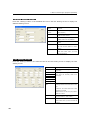
3. Menu Functions [For projector operation]
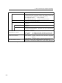
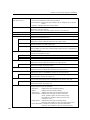
Title names
Displays the title name to be edited.
(pull-down menu)
- (Current): Indicates the title is being selected.
- Preset Button: Shows that the selected title is assigned to the preset
button.
- (Update): Indicates the title is being edited.
Select
Selects the title selected from the pull-down menu (an asterisk (*) is
attached to the title number).
Some of the buttons cannot be used if the title is not selected.
Delete
Deletes the title selected in the pull-down menu.
Store As...
Registers the title using the information displayed.
Input
A field that shows or sets the input terminal. Pressing the icon allows you to
change the corresponding icon.
PNG File
(Displayed only when the test pattern is selected.)
Displays the name of PNG file selected in the right column.
Component/RGB
(Displayed only when the test pattern is selected.)
Selects Component or RGB signal input.
MMS Setting
(Displayed only when MMS is selected.)
Sets the MMS. The name of the selected signal and Entry No. are displayed in
the right column.
Type
A field that shows or sets the input source. Pressing the icon allows you to
change the corresponding icon.
Format
Selects a format for the input source.
Data Type
Selects a data type for the input source.
Advanced
Sets the details of the input source.(See page 68)
PCF File Select
Selects a PCF file. (See page 67)
Displays the name of PCF file selected in the right column.
Setting
This button changes and saves the PCF file settings being used by the title
selected for output. (See page 6923)
MCGD File Select
Selects a MCGD file. (See page 67)
Displays the name of MCGD file selected in the right column.
SCREEN File Select
Selects a SCREEN file. (See page 67)
Displays the name of SCREEN file selected in the right column.
Setting
This button changes and saves the SCREEN file settings being used by the
title selected for output. (See page 72)
3D File Select
This button selects the 3D file. (See page 67)
The currently selected file name is displayed in the field on the right.
Setting
This button changes and saves the 3D file settings being used by the title
selected for output. (See page 73)
(View status)
Shows information on the title selected. Any information shown in this status
display space is set to the projector.
- Input Size:
Displays the input resolution setting.
- Aspect:
Displays the input aspect setting.
- Anamorphic:
Displays the setting of the anamorphic lens.
- Tolerance Box: Displays the setting of the white correction
mode. (Enable: White correction with priority
for brightness; Disable: White correction with
priority for color.)
- Image Scaler:
Displays the setting of the Image Scaler.
(Same as the indication in the Title Advanced screen.)
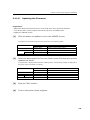
- Frame Rate Ratio: Displays the setting of the Frame Rate Ratio.
(Same as the indication in the 3D Controls screen.)
66
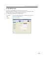
3. Menu Functions [For projector operation]
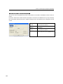
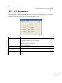
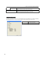
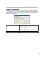
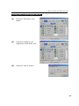
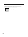
Selecting the Settings File
If you press the “*** File Select” button or the “Import” button, a screen is displayed for
selecting an existing settings file.
PCF File Select screen
Selects a PCF file.
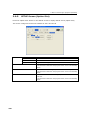
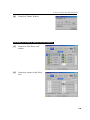
MCFD File Select screen
Selects a MCFD file.
SCREEN File Select screen
Selects a SCREEN file.
3D File Select screen
Selects a 3D file.
TCGD File Select screen
Selects a TCGD file.
LUT-CLUT File Select screen
Selects a LUT-CLUT file.
LUT-DG File Select screen
Selects a LUT-DG file.
Select the file to use and press the “Open” button to use the selected file. This screen is an
example of the PCF File Select screen.
“Open” button
Uses the selected file.
“Cancel” button
Returns to the previous screen.
67
3. Menu Functions [For projector operation]
3-7-1.
Title Advanced Screen
Press the “Advanced” button on the TITLE screen to display the Title Advanced screen. On the
Title Advanced screen you set the details of signal type.
For normal titles and MMS titles
For test patterns
Memory
Displays the title (number and name) selected.
Preset Button
Displays preset button numbers if preset buttons are assigned.
For assignment of preset buttons, refer to “3-3-1 Configuring the Preset
Buttons” (page 55).
“Lens Memory” Button
Select a lens memory to associate with the selected title when the lens
memory is used. Press the "Lens Memory" button to display the "Lens
Memory" screen. For the setup of lens memory, see the description of
"Memory List" buttons on the "LENS" screen. (See page 58)
- When you want to use the lens memory, select it from the "Lens Memory"
screen and press the "OK" button.
- When you do not want to use the lens memory, select "Not Use" from the
"Lens Memory" screen and press the "OK" button.
- The associated lens memory appears in the right column of the "Lens
Memory" button.
“Lamp Memory” Button
Select a lamp memory to associate with the selected title when the lamp
memory is used. Press the "Lamp Memory" button to display the "Lamp
Memory" screen. For the setup of lamp memory, see the description of
"Memory List" buttons on the "LAMP" screen. (See page 60)
- When you want to use the lamp memory, select it from the "Lamp Memory"
screen and press the "OK" button.
- When you do not want to use the lamp memory, select "Not Use" from the
"Lamp Memory" screen and press the "OK" button.
- The associated lamp memory appears in the right column of the “Lamp
Memory” button.
Image Scaler
Controls the scaling circuit. Keep Enable in normal operations.
Turret Title Select
Sets whether the power turret of anamorphic lens is used or not.
- With Anamo.
: Turret is used.
- Without Anamo. : Turret is not used.
“Exit” button
Used to save all the settings entered and quit the Title Edit
submenu/operation.
68
3. Menu Functions [For projector operation]
3-7-2.
PCF Setting Screen
Press the “Setting” button on the TITLE screen to display the PCF Setting screen. On the PCF
Setting screen, PCF files are created using the PCF Setting screen.
PCF File Name
Displays the name of PCF file selected.
“Import” button
Used to call an existing PCF file. (See page 67)
SOURCE File
The SOURCE file settings can be changed. Press the “Setting” button to display
the SOURCE Setting screen. (See page 70)
CSC File
The CSC file settings can be changed. Press the “Setting” button to display the
CSC Setting screen. (See page 70)
TCGD File
Selects a TCGD file. Press the “Import” button to display TCGD File Select
screen. (See page 67)
LUT-CLUT File
Selects a LUT-CLUT file. Press the “Import” button to display the LUT-CLUT File
Select screen. (See page 67)
LUT-DG File
Selects a LUT-DG file. Press the “Setting” button to display the LUT-DG screen.
(See page 71)
“Save” button
“Exit” button
Used to create a new PCF file. (Do not use this button in other cases.)
Returns to the TITLE screen. Press this button when you have entered all
values.
69
3. Menu Functions [For projector operation]
SOURCE Setting Screen
Press the “Setting” button in the SOURCE File field in the PCF Setting screen to display the
SOURCE Setting screen.
SOURCE
File
Displays the name of SOURCE file
Name
selected.
"Import"
Used to call an existing SOURCE file.
button
(See page 67)
Aspect Ratio
Enter or select the final aspect ratio
of the content entered.
Position
Sets the image display position.
Usually select 0 for all positions.
Input Size
Enter the effective area of the input
signal.
“Save” button
Used to create a new SOURCE file.
(Do not use this button in other
cases.)
“Exit” button
Returns to the previous screen.
Press this button when you have
entered all values.
CSC Setting Screen
Press the “Setting” button in the CSC File field in the PCF Setting screen to display the CSC
Setting screen.
CSC File Name
Displays the name of CSC file selected.
"Import" button
Used to call an existing CSC file. (See
page 67)
Coefficience
To change the setting, enter a number.
Offset
This does not normally need to be
Brightness
changed.
Contrast
Saturation
Hue (deg)
“Set all 3” check
This is used when setting all of the
box
setting values to the same value in one
go.
Checked: The value entered in G also
applies to R and B.
Not checked: You can set G, R, and B to
different values.
“Save” button
Used to create a new CSC file. (Do not
use this button in other cases.)
“Exit” button
Returns to the previous screen. Press
this button when you have entered all
values.
70
3. Menu Functions [For projector operation]
LUT-DG Setting Screen
Press the “Setting” button in the LUT-DG File field in the PCF Setting screen to display the
LUT-DG Setting screen.
File Select
You should normally select “File Select”.
Parametric
"Import" button
Used to call an existing LUT-DG file.
(See page 67)
“OK” button
Confirms the settings.
“Cancel” button
Abandons the settings and returns to
the previous screen.
71
3. Menu Functions [For projector operation]
3-7-3.
SCREEN Setting Screen
Press the “Setting” button in the SCREEN File Select field in the TITLE screen to display the
SCREEN Setting screen. This screen is used to create new SCREEN files and to modify the
settings in previously created SCREEN files.
72
3. Menu Functions [For projector operation]
3-7-4.
3D Controls Screen
Press the “3D Controls” button in the 3D File Select field of the Title screen to display the 3D
Controls screen. This screen is used to create new 3D files and to change the settings in
previously created 3D files.
73
3. Menu Functions [For projector operation]
3-8. INFO Screen
Press the “INFO” button on the menu bar to display the INFO screen.
The INFO screen is made up of the following four screens that allow you to check information
and various logs of the projector main unit and multi media switcher.
- Status:
Allows you to check version information and error information for the projector main
unit, ICP board, and multi media switcher (MMS). You can also save the logs that are
saved in the projector main unit onto a computer. (See page 75)
- Status2: Allows you to check the states of slot A and slot B in the projector main unit and the
installation complete date of the projector main unit (warrantee start date). (See
page 78)
- Log:
Allows you to check the state of the projector main unit and the various logs. (See
page 79)
- SIB:
Allows you to check the status and version information of the signal input board
itself and the security circuit (Enigma) on the signal input board. (See page 89)
74
3. Menu Functions [For projector operation]
3-8-1.
INFO Screen (Status)
Press the “Status” button on the INFO screen to display the INFO screen (Status).
You can check version information and error information for the projector main unit CPU board,
ICP board, and multi media switcher (MMS) using this screen. You can also save the logs that
are saved in the projector main unit onto a computer.
System
Displays the version information of the projector main unit and the CPU
board in the projector.
Serial
Displays the serial number of the CPU board.
BIOS
Displays the BIOS version of the CPU board.
Firmware
Displays the firmware version of the CPU board.
Data
Displays the data version of the CPU board.
System Usage
Displays the hours of use of the projector main unit.
IP Address
Displays the IP address and the subnet mask of the projector main unit.
MMS
Displays the version information of the MMS connected to the projector
head.
Serial
Displays the serial number of the MMS.
BIOS
Displays the BIOS version of the MMS.
Firmware
Displays the firmware version of the MMS.
Data
Displays the data version of the MMS.
FPGA
Displays the FPGA version of the MMS.
Cfg FPGA
Displays the Configuration FPGA version of the MMS.
IP Address
Displays the IP address of use of MMS.
Cinema Board
Displays the version information of the ICP board or Satellite board.
ICP
Satellite
Displays the ICP system working version.
Red
Displays the satellite board type of the ICP board (2xLVDS/DDR).
Green
Blue
DMD
Displays the DMD type (0.98” DC2K/1.2” DC2K).
75
3. Menu Functions [For projector operation]
“ICP Status” button
Displays the ICP Status screen. (See page 76)
Displays detailed information about the ICP board.
Error
Displays the error currently occurring.
“Save Information” button
Saves various information about the CPU board, the ICP board, the
MMS and the signal input board (SIB) in text format.
ICP Status Screen
Press the “ICP Status” button in the Cinema Board field of the INFO screen (Status) to display
the ICP Status screen. You can check the status of the ICP board using this screen.
“Refresh” button
Updates the displayed contents to
“Exit” button
Returns to the previous screen.
the newest information.
76
3. Menu Functions [For projector operation]
Log Filter Setting Screen
Press the “Save Information” button in the Error field of the INFO screen (Status) to display the
Log Filter Setting screen. This screen is used to configure whether or not to save the log of when
the lamp bulb, lamp housing, fans, and air filters are reset (Usage Reset Log) to match the
period of the log saved on the PC.
“Include Usage Reset Log” check box
Sets whether or not to include the log of when the lamp bulb,
lamp housing, fans, and air filters are reset (Usage Reset Log)
in the log saved on the PC.
Checked:
Includes the Usage Reset Log when saving the
log
Not checked: Does not include the Usage Reset Log when
saving the log
“Save” button
Saves the log onto the PC using the configured settings.
“Exit” button
Returns to the previous screen.
77
3. Menu Functions [For projector operation]
3-8-2.
INFO Screen (Status2)
Press the “Status2” button on the INFO screen to display the INFO screen (Status2).
You can check the states of slot A and slot B in the projector main unit and the installation
complete date of the projector main unit (warrantee start date) using this screen.
Option Slot Status
Displays information about slot A and slot B. The slot settings are
configured from the SETUP screen (Option Slot).
Slot B
Displays the settings of slot B. Parentheses () are added to the device
name when the projector is in standby mode or the installed devices
cannot be identified.
Slot A
Displays the settings of slot A. Parentheses () are added to the device
name when the projector is in standby mode or the installed devices
cannot be identified.
Setup Date
Displays the installation complete date when of the projector
(warrantee start date). The installation complete date is configured
from the UPDATE screen.
System
Displays the installation complete date (warrantee start date) of the
projector as saved in the CPU board.
Key
Displays the installation complete date (warrantee start date) of the
projector as saved in the Key board.
DIV
Displays the installation complete date (warrantee start date) of the
projector as saved in the DIV board.
78
3. Menu Functions [For projector operation]
3-8-3.
INFO Screen (Log)
Press the “Log” button on the INFO screen to display the INFO screen (Log).
You can check the various logs saved in the projector main unit from this screen.
"System Status" button
Displays the System Status screen. (See page 81)
This displays the temperature, voltage, and fan speed inside the
projector main unit.
“Error Log” button
Displays the System Error Log screen. (See page 83)
This displays CPU board error information.
“Cinema System Log” button
Displays the Cinema System Log screen. (See page 83)
This displays ICP board error information.
“Usage Reset Log” button
Displays the User Reset Log screen. (See page 84)
This displays various information about when the usage times of
the lamp bulb, lamp housing, fans, and air filters were reset.
“Temperature Log” button
Displays the Temperature Log screen. (See page 85)
This displays a record of the temperature from when the projector
was turned on until it was turned off (peak hold).
“Power Supply Log” button
Displays the Power Supply Log screen. (See page 86)
This displays a record of the voltage from when the projector was
turned on until it was turned off (peak hold).
“FAN Speed log” button
Displays the FAN Speed Log screen. (See page 87)
This displays a record of the fan speed (minimum value) from when
the power was turned on until it was turned off.
“Operation Log” button
Displays the Lamp Operation Log screen. (See page 88)
This displays a record of the operation of the projector.
“Secure Log(Cinema)” button
Displays the Secure Log (Cinema) screen. (See page 88)
This displays a log of the security circuit (Enigma) on the signal
input board.
79
3. Menu Functions [For projector operation]
Log Filtering Function
Press the “Filter” button to display the Log Filter Setting screen. You can set the period of logs
to display using this screen.
Log Filter Setting screen
Today
Displays only the log for today.
7days
Displays the log for the last 7 days including today.
30days
Displays the log for the last 30 days including today.
Manual
Displays the log for the specified period (from From to To).
From:
Selects the start date of the period for which to display the logs.
To:
Selects the end date of the period for which to display the logs.
Click “Today” in the calendar to set to today’s date.
80
“OK” button
Displays the logs that match the specified conditions.
“Cancel” button
Cancels the settings and returns to the previous screen.
3. Menu Functions [For projector operation]
System Status Screen
This screen displays the temperature, voltage, and fan speed inside the projector main unit.
Click the “Temperature”, “Power Supply”, and “FAN Speed” tabs to switch between the items
displayed.
System Status screen (Temperature)
Outside Air
Displays the temperatures of each part of the projector. Refer to
LPSU Intake
the "Service Manual" for details.
Exhaust
DMD-B
Temp 5
Temp 6
Temp 7
Temp 8
MAX6656
ICP FPGA
FMT FPGA
Current
Upper Limit
“Refresh” button
Updates the displayed contents to the newest information.
“Exit” button
Returns to the previous screen.
81
3. Menu Functions [For projector operation]
System Status screen (Power Supply)
System
Displays the voltage of the projector.
Current
Displays the current voltage.
Min
Displays the upper limit value of the voltage. An error occurs if the voltage
exceeds this value.
Max
Displays the lower limit value of the voltage. An error occurs if the voltage
drops below this value.
ICP
Displays the ICP board voltage.
“Refresh” button
Updates the displayed contents to the newest information.
“Exit” button
Returns to the previous screen.
System Status screen (FAN Speed)
Fan 0 to Fan 9
Lamp Cooling Fan 0
Displays the fan speed.
Min
Lamp Cooling Fan 1
Pump
Displays the lower limit value of the fan speed. An error occurs if
the fan speed drops below this value.
Precaution
ICP Fan
Displays the warning value of the fan speed. A warning occurs if
the fan speed drops below this value.
Current
Displays the current voltage.
Max
Displays the upper limit value of the fan speed. An error occurs if
the fan speed exceeds this value.
82
“Refresh” button
Updates the displayed contents to the newest information.
“Exit” button
Returns to the previous screen.
3. Menu Functions [For projector operation]
System Error Log Screen
This screen displays a log of CPU board errors.
“Filter” button
Sets the period of the log to
“Exit” button
Returns to the previous screen.
“Filter” button
Sets the period of the log to
“Exit” button
Returns to the previous screen.
display. (See page 77)
Cinema System Log Screen
This screen displays a log of ICP board errors.
display. (See page 77)
83
3. Menu Functions [For projector operation]
Usage Reset Log Screen
This screen can be displayed in Service mode only. When usage times of the lamp bulb, lamp
housing, fans, and air filters are reset, the following items are saved with the values
immediately before reset treated as the log information when the utilization hours are reset.
This screen shows 64 items at most (64 items from the newest one are displayed).
No.
Displays the record No.
Date/Time
Displays the date and time.
Reset
Displays the reset subject.
- Lamp bulb:
Bulb
- Lamp house: House1/House2
- Fan:
AC On Fan/Power On Fan
- Air filter:
Body Filter/Lamp Filter
System
Displays the utilization hours of the projector main unit.
Bulb
Displays the utilization hours of lamp bulb.
House1
Displays the utilization hours of lamp house 1.
House2
Displays the utilization hours of lamp house 2.
Bulb Name
Displays the bulb entry name.
Min[A]
Displays the minimum current value (A).
Max[A]
Displays the maximum current value (A).
Typical
Displays the lamp output (kW) average.
Max[W]
Displays the maximum value of lamp output (kW).
Warning Time
Displays the warning time.
Bulb Warning
Displays the currently enabled warning time set by the Bulb Warning setting.
AC On Fan
Displays the speeds of the projector cooling fans (AC On Fan).
Refer to the "Service Manual" for details.
Power On Fan
Displays the speeds of the projector cooling fans (Power On Fan).
Refer to the "Service Manual" for details.
84
Lamp Fan
Displays the speeds of the lamp cooling fan.
Body Filter
Displays the usage time of the air filters for the projector head.
Lamp Filter
Displays the usage time of the air filters for the lamp.
“Clear” button
Clears the usage reset log and closes the screen.
“Refresh” button
Updates the displayed contents to the newest information.
“Exit” button
Returns to the previous screen.
3. Menu Functions [For projector operation]
Temperature Log Screen
This screen displays the maximum temperature recorded in the period from when the projector
was turned on until it was turned off.
The upper half of the screen displays the maximum temperatures measured and dates and
times for each item from when the power was last turned on until now. The information that is
saved in the log when the power is turned off is displayed in sequential order in the lower half
of the screen. When saved as a log, information at the time when the log was recorded (all
temperatures, fan speeds, and lamp outputs within the projector) is also saved in addition to
the maximum temperature and date and time of each item.
You can switch between the number of items displayed (all items or maximum temperatures
only) by pressing the [<] button.
“Filter” button
Sets the period of the log to display. (See page 77)
Temp.
Displays the item where the maximum temperature was measured.
Max Val.
Displays the maximum temperature.
Outside Air
Displays the temperature at the Date/Time.
LPSU Intake
Exhaust
DMD-B
Temp5
Temp6
Temp7
Temp8
Fan 0 to Fan9
Displays the fan speed at the Date/Time.
Lamp Cooling Fan 0
Lamp Cooling Fan 1
Pump
ICP Fan
Displays the lamp output at the Date/Time.
Lamp Output
Displays the date and time when the maximum temperature was measured.
“Exit” button
Returns to the previous screen.
85
3. Menu Functions [For projector operation]
Power Supply Log Screen
This screen displays the maximum and minimum voltage values recorded in the period from
when the projector was turned on until it was turned off.
The upper half of the screen displays the maximum/minimum voltages measured and dates and
times for each item from when the power was last turned on until now. The information that is
saved in the log when the power is turned off is displayed in sequential order in the lower half
of the screen.
“Filter” button
Sets the period of the log to display. (See page 77)
Date/Time
Displays the date and time when the maximum/minimum voltage
Power Supply
Displays the item where the maximum/minimum voltage was
was measured.
measured.
(Max): Displays the maximum value.
(Min): Displays the minimum value.
86
Voltage
Displays the measured voltage.
“Exit” button
Returns to the previous screen.
3. Menu Functions [For projector operation]
FAN Speed Log Screen
This screen displays the minimum fan speeds recorded in the period from when the projector
was turned on until it was turned off.
The upper half of the screen displays the minimum fan speeds measured and dates and times
for each item from when the power was last turned on until now. The information that is saved
in the log when the power is turned off is displayed in sequential order in the lower half of the
screen.
“Filter” button
Date/Time
Sets the period of the log to display. (See page 77)
Displays the date and time when the minimum fan speed was
measured.
Fan Type
Displays the type of fan.
rpm(Min)
Displays the fan speed (minimum value).
“Exit” button
Returns to the previous screen.
87
3. Menu Functions [For projector operation]
Operation Log Screen
This screen displays a record of the operation of the projector.
“Filter” button
Sets the period of the log to display. (See page 77)
“Exit” button
Returns to the previous screen.
Secure Log(Cinema) Screen
This screen displays a log of the security circuit (Enigma) on the signal input board.
“Exit” button
88
Returns to the previous screen.
3. Menu Functions [For projector operation]
3-8-4.
INFO Screen (SIB)
Press the “SIB” button on the INFO screen to display the INFO screen (SIB).
This screen displays version information about the signal input board and version information
about Enigma (the security circuit built into the signal input board)
SIB Version
Displays information about the signal input board.
Main
Displays version information about the signal input board.
OS
Displays OS version information about the signal input
board.
BIOS
Displays BIOS version information about the signal input
board. Currently, “---” is displayed.
Firmware
Displays firmware version information about the signal input
board.
FPGA H/W
Displays FPGA H/W version information about the signal
input board.
FPGA S/W
Displays FPGA S/W version information about the signal
input board.
“Current Status” button
Displays the SIB Status screen. (See page 90)
Displays version information about the SDI input port of the
signal input board.
Enigma Version
Displays information about the security circuit (Enigma)
built into the signal input board.
Enigma
Displays version information about Enigma.
FPGA Firmware
Displays version information about the FPGA firmware.
Login List
Displays version information about the Login List.
Security Officer List
Displays version information about the Security Officer List.
“Enigma Status” button
Displays the Enigma Status screen. (See page 90)
Displays detailed information about Enigma.
89
3. Menu Functions [For projector operation]
SIB Status Screen
Press the “Current Status” button on the INFO screen (SIB) to display the SIB Status screen.
This screen displays detailed information about the SDI input ports (SDI-A, SDI-B, SDI-C, and
SDI-D) on the signal input board.
SDI Status
Displays detailed information
on the SDI input status.
- Carrier Detect
- SDT Lock
- STD
- CRC Error
Error Total
Displays
information
about
the accumulated errors.
Error Frame
This
displays
error
information within one frame.
“Refresh” button
Updates
contents
the
to
displayed
the
newest
information.
“Exit” button
Returns
to
the
previous
screen.
Enigma Status Screen
Press the “Enigma Status” button on the INFO screen (SIB) to display the SIB Status screen.
This screen displays detailed information about Enigma (the security circuit built into the signal
input board).
“Refresh” button
Updates
contents
the
to
displayed
the
newest
information.
“Exit” button
Returns
screen.
90
to
the
previous
3. Menu Functions [For projector operation]
3-9. SETUP Screen
This menu is only available in the Installation or Service mode.
Display and setting are available even when the projector is in the standby status.
Press the “SETUP” button on the menu bar to display the SETUP screen.
The SETUP screen consists of five windows below.
- Setup
: Use this window for configuring various settings for the projector. (this page)
- Installation
: Use this window for setting at installation. (See page 95)
- Color Setting : Use this window for making color adjustments. (See page 98)
- MMS Setting : Use this window for configuring the MMS connection settings. (See page 99)
- Option Slot
3-9-1.
: Use this window for setting for slot A or slot B. (See page 100)
SETUP Screen (Setup)
Press the "Setup" button on the "SETUP" screen to display the "SETUP (Setup)" window.
The operating settings of the projector main unit are configured using this screen.
Douser Mode(Title Select)
The douser function is enabled when the signal is changed.
Disable
The lens douser function will be not activated during the switching of
signals.
Enable
The lens douser function will be activated during the switching of
signals.
91
3. Menu Functions [For projector operation]
Douser Mode(Power On)
Sets the douser status (Open/Close) when the projector is turned on.
Open
Displays the lens douser when the projector is turned on.
Close
Closes the lens douser when the projector is turned on.
Panel Key Lock
The control buttons on your projector are locked to be inoperative.
Unlock
Disable the lock on the control buttons.
Lock
Enable a lock on the control buttons on your projector.
Turret
Controls the turret on which the anamorphic lens is mounted.
Manual
Automatic
Manually control the turret.
The anamorphic lens selected at Title switches automatically when
the title is switched.
Turret Ref. Select
Sets the initial setting (use or not use) of the turret. This setting is
applied when you create a new title.
- Without Anamo:
Disables anamorphic lens.
- With Anamo:
Enables anamorphic lens.
Factory Default
Resets all adjustment and setting values stored to the projector and all registered titles and
preset button assignment to the statuses when shipped from the factory.
92
P Button & Title
Resets the preset button assignment and all registered titles.
All
Resets all data.
3. Menu Functions [For projector operation]
GPIO
Press the “Setting” button in the GPIO field of the SETUP screen (Setup) to display the GPIO
Setting screen.
You can change the function that is allocated to the GPIO port of the projector, the timing with
which GPIO control is executed, etc. from this screen. Refer to the user's manual of the
projector for details on the GPIO port.
GPI 0 to GPI 15
Allocates functions to EXT_GPIN1 to EXT_GPIN4.
Refer to the following page for details on the correspondence
between GPI and EXT_GPIN.
GPO_1 to GPO_4
Allocates functions to EXT_GPOUT1 to EXT_GPOUT4.
Projector Heartbeat
Sets the heartbeat output interval.
Ready/Busy Bit Assign
Configures the logic setting of the Ready/Busy bit of the GPIO
control.
Projector Error Status Bit Assign
IMB Play/End Status Bit Assign
Configures the logic setting of the error status bit of the projector.
Configures the logic setting of the bit for confirming the status of
media block operation.
Idle effective pulse width
Configures the OFF pulse width that is required before inputting an
ON pulse.
Each Function effective pulse width
Configures the pulse width after an ON pulse is input until the GPIO
function is executed.
“OK” button
Applies the settings that have been selected.
“Cancel” button
Cancels the settings and returns to the previous screen.
93
3. Menu Functions [For projector operation]
The correspondence between GPI 0 to GPI 15 and EXT_GPIN is shown in the following table.
EXT_GPIN4
EXT_GPIN3
EXT_GPIN2
EXT_GPIN1
(Pin No. 8-27)
(Pin No. 7-26)
(Pin No. 6-25)
(Pin No. 5-24)
GPI 0
OFF
OFF
OFF
OFF
GPI 1
OFF
OFF
OFF
ON
GPI 2
OFF
OFF
ON
OFF
GPI 3
OFF
OFF
ON
ON
GPI 4
OFF
ON
OFF
OFF
GPI 5
OFF
ON
OFF
ON
GPI 6
OFF
ON
ON
OFF
GPI 7
OFF
ON
ON
ON
GPI 8
ON
OFF
OFF
OFF
GPI 9
ON
OFF
OFF
ON
GPI 10
ON
OFF
ON
OFF
GPI 11
ON
OFF
ON
ON
GPI 12
ON
ON
OFF
OFF
GPI 13
ON
ON
OFF
ON
GPI 14
ON
ON
ON
OFF
GPI 15
ON
ON
ON
ON
Auto Key Lock
Automatically locks the control buttons on your projector so that they cannot be used. When the
auto key lock function is enabled, the key lock is set under the following conditions.
- When the projector enters the standby state, the key lock is activated.
- When no operations are performed on the control panel of the projector main unit for 30
seconds or more, the key lock is activated.
If you press the KEY LOCK button on the projector for one second or longer, the key lock is
cleared, but the key lock is automatically locked applied again if the key lock conditions are
satisfied.
Disable
Disables the auto key lock function.
Enable
Enables the auto key lock function.
3D Connector
Selects the port for 3D video systems used as the control signal input/output for the 3D video
system.
If you select “Not Use”, the GP I/O port is used as the control signal input/output for the 3D
video system.
Not Use
Does not use the 3D port as the control signal input/output for the 3D
video system (uses the GP I/O port).
Use
Uses the 3D port as the control signal input/output for the 3D video
system.
94
3. Menu Functions [For projector operation]
3-9-2.
SETUP Screen (Installation)
Press the “Installation” button on the SETUP screen to display the SETUP screen (Installation).
The SETUP screen (Installation) is used to configure the settings required when the projector is
installed, change the passcodes, adjust the lens center, calibrate the lens, and perform
re-marriage.
Baudrate
To select the transmission speed (bps) for your projector (SYSTEM) and a PC when they are
connected by a commercially available RS-232C straight cable. Select one from 4800, 9600,
19200 and 38400. Select the transfer speed corresponding to the speed of the connected
devices.
95
3. Menu Functions [For projector operation]
Date/Time
Use this to set the date and time on the projector.
The internal clock in the projector operates on coordinated universal time (UTC). You can set
the internal projector time to the time in your region by setting the time difference between the
standard time in your region and UTC.
UTC Time
Displays the universal coordinated time.
Projector Time
Displays the date and time of the projector main unit.
Adj.
Adjusts the projector time in units of one hour.
▲:
Adds one hour.
“PC Local” button
Sets the projector time to the time on the PC.
“Apply” button
Updates it in the changed Date/Time.
▼:
Subtracts one hour.
Language (DCC)
Select a language that is displayed on the menu. The menu language of this software(DCC) is
switched (Only the English language is supported as the menu language of the projector main
unit).
English
中文
“OK” button
Displays in English.
Displays in Chinese (simplified characters).
Changes the language selected as the language to display in the DCC
menus.
“Cancel” button
96
Abandons the settings and returns to the previous screen.
3. Menu Functions [For projector operation]
Passcode
Use this to change the pass code of the Installation mode or the Advanced User mode.
- Enter new passcode: Input new pass code.
- Enter new passcode to confirm: Input new pass code to confirm.
Enter new passcode
Input new pass code.
Enter new passcode to
Input new pass code to confirm.
confirm
“Apply” button
The new passcode is activated.
“Cancel” button
Abandons the settings and returns to the previous screen.
Lens Center
Press the “Execute” button to move the lens shift position to the center. The center position may
slightly shift depending upon mounting conditions of the lens.
Lens Calibrate
Calibrate Zoom and the Focus lens (support by the NC2000/1200 Series only).
Execute this function whenever replacing the lens.
Enigma Re-Marriage
This menu can only be used when the projector is turned on.
If the marriage has been cleared, it can be reconfigured by performing re-marriage.
Press the “Re-Marriage” button to display the login window. Enter your ID and password to
reconfigure the marriage. Please ask the service personnel for the ID and password.
97
3. Menu Functions [For projector operation]
3-9-3.
SETUP Screen (Color Setting)
This screen can only be configured when the projector is turned on.
Press the “Color Setting” button on the SETUP screen to display the SETUP screen (Color
Setting). This screen is used to adjust the colors. For details of the settings, see "2-2. Adjusting
Colors" (See page. 16).
MCGD Setup
Used for the MCGD settings.
“Create” button
Start creating the MCGD data. Upon input completion, press the
[Save] button to save the settings.
“Select” button
TCGD Setup
Used to call an existing MCGD file. (See page XX)
Set a target color (TCGD). In Pospro mode, the TCGD Setup screen is
displayed. On the TCGD Setup screen, more detail target color
(TCGD) setup is enabled.
98
“Native” button
Used for the Native color.
“Select” button
Used to call an existing TCGD file. (See page XX)
3. Menu Functions [For projector operation]
3-9-4.
SETUP Screen (MMS Setting)
Press the “MMS Setting” button on the SETUP screen to display the SETUP screen (MMS
Setting).
MMS Select
Select the “Built-in” when you use an optional multimedia switcher
(MMS).
“Not Use” button
Not to use MMS.
“Built-in” button
To use the incorporated MMS (optional).
99
3. Menu Functions [For projector operation]
3-9-5.
SETUP Screen (Option Slot)
Press the “Option Slot” button on the SETUP screen to display SETUP screen (Option Slot).
This screen configures the devices installed in slot A and slot B.
Option Status
Configures the devices mounted in slot A and slot B.
Slot B
Selects the devices mounted in slot B.
Slot A
Selects the devices mounted in slot A.
“Apply” button
Applies the settings that have been selected.
“Reset Slot B” button
Resets slot B in an emergency. You should not normally use this.
This cannot be used when the projector main unit is in the standby
state.
“Reset Slot A” button
Resets slot A in an emergency. You should not normally use this.
This cannot be used when the projector main unit is in the standby
state.
“Reset Slot ICP” button
Resets the ICP board in an emergency. You should not normally
use this.
This cannot be used when the projector main unit is in the standby
state.
100
3. Menu Functions [For projector operation]
3-10. LAN Screen
This menu is only available in the Installation or Service mode.
Display and setting are available even when the projector is in the standby status.
Press the “LAN” on the menu bar to display the LAN Screen.
The "LAN" screen consists of three windows below.
- IP Address
: Used when making LAN settings of SYSTEM. (See next page)
- Mail
: Used to set up mail function.
- SNMP
: Used to set up SNMP.
101
3. Menu Functions [For projector operation]
3-10-1. LAN Screen (IP Address)
Press the “IP Address” button on the LAN screen to display the LAN (IP address) screen.
This screen is used to configure the IP address of the projector main unit.
Automatic/Manual
Select Automatic if IP address is automatically assigned by a DHCP server through
the network connected to your projector. If not, select Manual. In this case, you
must make entries in the IP Address and Subnet Mask fields.
Automatic ---
IP address, subnet mask and gateway are automatically assigned by a
DHCP server.
Manual ---
IP address, subnet mask, etc. are assigned by the network
administrator. Entries are required.
System IP Address
Set/display the IP address of the projector main unit.
Subnet Mask
Set/display the subnet mask number.
System Name
To display/set the identification name of the system board on the network
Gateway
Set/display the default gateway of the network connected to the Projector.
DNS Configuration
Type in the IP address of DNS server on the network connected to the Projector.
Host Name
To display/set the identification name of the projector main unit on the network
Domain Name
Type in domain name of the network connected to the Projector.
“Apply” button
102
Used to apply the entered settings.
3. Menu Functions [For projector operation]
3-10-2. LAN Screen (Mail)
Press the “Mail” button on the LAN screen to display the LAN (Mail) screen.
This screen is used to configure the settings for sending projector status notifications by email.
Alert Mail
This option notifies your computer of an error message via email when using
wireless or wired LAN.
Sender’s Address
- Check On:
To enable the mail notification function
- Check off:
To disable the mail notification function
Enter the sender's address for the email from your projector. This address is for
“From:” of the email.
SMTP Server Name
Set the SMTP server of the network to which the projector is connected.
Recipient’s Address 1
Enter the recipient's address for the email from your projector. You can set up to
Recipient’s Address 2
3 recipient’s addresses. This address is for “To:” of the email.
Recipient’s Address 3
“Test Mail” button
Click on this button to check the email data you have entered above.
“Apply” button
Change contents are updated.
103
3. Menu Functions [For projector operation]
3-10-3. LAN Screen (SNMP)
Press the “SNMP” button on the LAN screen to display the LAN (SNMP) screen.
This screen is used to configure Simple Network Management Protocol (SNMP) settings.
Read
Sets the IP address and the community name used for reading from the SNMP
manager.
Write
Sets the IP address and the community name used for writing from the SNMP
manager.
Trap
Sets the IP address and the community name of the Trap destination. You can
specify 3 Trap destinations at most.
- With check mark
: To send Trap to the destination specified in the right
space
- Without check mark : Not to send Trap to the destination specified in the right
space
104
Set Critical Error List
Sets the details of errors that send a trap. (See page XX)
“Apply” button
Change contents are updated.
3. Menu Functions [For projector operation]
Critical Error List Screen
Press the “Set Critical Error List” button on the LAN screen (SNMP) to display the Critical Error
List screen. You can configure the error details that send an SNMP trap by using this screen.
If an error that has the check box is selected occurs, an SNMP trap (trap number 2) is sent. The
default setting is for all of the check boxes to be cleared.
“Check All On” button
Selects all of the items.
“Check All Off” button
Clears all of the items.
“OK” button
Confirms the settings.
“Cancel” button
Cancels the settings and returns to the previous screen.
105
3. Menu Functions [For projector operation]
3-11. UPDATE Screen
This menu can be used in Service mode only. This menu can be displayed/set even if the
projector main unit is in standby state.
When the “UPDATE” button in the menu bar is pressed, the UPDATE screen is displayed.
Backup to PC
skip PNG Files
“Titles” button
“All Cinema Files” button
“Set Settings” button
Compare
“Compare Cinema File”
button
Restore from PC
skip MCGD Files
“Restore” button
Update
“System Firmware” button
“System Data” button
ICP Update
“ICP firmware” button
Setup Date
“Setting” button
Factory Test
“Maintenance” button
106
Saves the Cinema file that is registered in this device in the PC.
Check on this option when omitting backup of the PNG file.
Backs up the information for the 100 titles registered in the projector main unit
and the files saved on the ICP board to a pre-specified folder.
The index file that can be used by Restore is generated.
Information on the lens memory and lamp memory is not saved.
Backs up all the files of the ICP board. At the same time, an Index file such as a
batch file is generated. The index file that can be used by Restore is generated.
Backs up user setting information to a pre-specified folder. The index file that can
be used by Restore is generated.
Compares the cinema files on the ICP board registered in the projector with the
cinema files backed up in the specified folder. (See page 109)
The cinema files on the ICP board are compared to the cinema files backed up in
the specified folder using the file names and timestamps of the files, and the
result is displayed in the Compare screen.
Restores the title information registered in the projector main unit, the cinema
files in the ICP board, and the user settings information that was saved using
Backup to PC.
Check on this option when omitting restoration of the MCGD file. Since some
MCGD files are large, restoration requires a long time.
Reads the selected Index file and executes a restore.
Writes the firmware and data of the NC projector in this device. (See page 115)
Executes updating of the firmware of the CPU board.
Executes updating of the system data of the CPU board.
Writes the firmware of the ICP board. (See page XX)
Executes updating of the IPC board.
Configures the date when the projector was set up (starting date of the warranty
period).
Configures the date when the projector was set up. This is used to copy from the
backup information when new settings are created or boards are replaced.
Executes the inspection function that is used at the factory. You cannot normally
use this.
Executes the inspection function. You cannot normally use this.
3. Menu Functions [For projector operation]
Information Viewer
“Information
button
Check Version
Viewer”
“Check” button
SIB Update
“Firm & FPGA Update”
button
Enigma Update
“Enigma firmware” button
ICP/Enigma Update
“Secure Data” button
Enigma RTC
“Enigma RTC” button
Enigma Input
“Bypass” button
“Macro File Tools” button
Checks the log file that was saved using “Save Information”. (See page 111)
Starts the Information Viewer.
Checks whether or not the versions of the CPU board, ICP board, signal input
board, and Enigma on the projector main unit match the specified versions. (See
page 113)
Executes a check of the version information.
Writes the firmware and FPGA of the signal input board. (See page 115)
Executes updating of the signal input board.
Writes the firmware of the Enigma. (See page 115)
Executes updating of the Enigma.
Updates the Secure Data in the ICP board and Enigma. (See page 115)
Executes updating of the secure data of the ICP board and the Enigma.
This can only be used when the projector is turned on. Sets the internal clock of
Enigma.
The internal clock of Enigma is set to the date and time of the PC.
This can only be used when the projector is turned on.
Temporarily disables the security circuit of the SDI input port of the signal input
board (for debugging).
This is cleared if any of the following conditions are met.
- A title is selected
- The projector is turned off
- SIB Reset is performed
Disables the security circuit of the SDI input port of the signal input board.
Starts the Macro File Tool. The Macro File Tool is used to confirm that the cinema
files used by the titles registered in the projector main unit exist. Refer to the
Service Manual for details.
107
3. Menu Functions [For projector operation]
3-11-1. Backing Up and Restoring Setting Information
You can backup the cinema file, title information, and projector setting information to a PC by
using Backup to PC on the UPDATE screen. Setting information that has been backed up can be
restored by using Restore from PC on the UPDATE screen.
Format of Index file names
The format of the Index file names that are automatically generated during a backup is as
follows.
<Projector model name> + <Main unit firmware version> + <Backup type>.txt
Example: If the title information is backed up on an NC2000 series with firmware version
012345, an Index file named “nc20bk012345idxT.txt” is created.
Projector model names
Backup types
NC1200 Series
: nc12bk
NC2000 Series
: nc20bk
NC3200 Series
: nc32bk
Titles
: idxT
All Cinema Files
: idxC
Set Settings
: idxS
Files and Setting Information that is Backed Up
Title information (Titles)
Backs up the title information that is registered in the projector
and the Cinema files that are needed in order to display the titles.
Cinema file (All Cinema Files)
Files with the following file extensions that are saved on the ICP
board are backed up (You can select whether or not to include
PNG files in the backup).
.MACRO/.PCF/.MCGD/.SCREEN/.SOURCE/.3D/.PNG
Setting information (Set Settings)
Backs up the user setting information (ncuser.bin).
States Where Backup and Restore can be Performed
The projector states where backup and restore can be performed are shown in the following
table.
Backup
Title information (Title: idxT)
Cinema file (All Cinema Files: idxC)
Setting information (Set Settings: idxS)
Restore
Turned on state
Turned on state
Standby state and
power-on state
108
Standby state
3. Menu Functions [For projector operation]
3-11-2. Comparing Cinema Files
Press the “Compare Cinema Files” button on the UPDATE screen to display the file selection
screen. When you select the Index file created when the cinema files being compared were
backed up, the Compare screen is displayed.
The cinema files on the ICP board registered in the projector are compared with the cinema files
backed up in the specified folder by using this screen. Timestamps are used to compare the
files.
Cinema file comparisons can only by used when the projector is turned on.
List Filter
Displays only files with the selected file extension.
Select List
Configures how files are selected on the PC.
“New File” button
Executes a cinema file comparison and selects all of the
files where the timestamp is different.
“All” button
Selects all of the files on the PC.
“Manual” button
Allows you to select the files on the PC manually.
Loosely compare(for FAT32)
When this checkbox is selected, differences in the seconds
part of the timestamps are ignored.
“Delete” button
Deletes the selected files from the projector.
“Restore” button
Transfers the files selected on the PC to the projector.
“Exit” button
Closes the Compare windows.
109
3. Menu Functions [For projector operation]
3-11-3. Setting the Setup Date of the Projector
Press the “Setting” button in the Setup Date field of the UPDATE screen to display the Setup
Date window.
This screen is used to set the setup date (warrantee start date) of the projector. The projector
setup date data is saved in three locations (CPU board, Key board, DIV board). If any of this
data is lost, the record of the setup date can be restored from the remaining data. Always set
the setup date to the same date.
“Setup Date of System update to the
Restores the setup date on the CPU board.
other boards” button
This is used when the CPU board is repaired or replaced.
“Setup Date of Key update to the
Restores the setup date on the Key board.
other boards” button
This is used when the Key board is repaired or replaced.
“Setup Date of DIV update to the
Restores the setup date on the DIV board.
other boards” button
This is used when the DIV board is repaired or replaced.
“New Setup” button
This is used to newly set the setup date. This sets the setup date on
the CPU board, Key board, and DIV board to the current date. Do
not use this except when installing the projector.
“Exit” button
110
Closes the Setup Date window.
3. Menu Functions [For projector operation]
3-11-4. Checking Log Files Using the Information Viewer
Press the “Information Viewer” button in the UPDATE screen to display the file selection screen.
When you select a log file, the log is displayed in the Information Viewer. In the Information
Viewer, you can use the following functions to easily check the log files.
- Sort and display logs in time order
- Switch the time in the logs between UTC and projector main unit time
- Highlight rows that contain specified keywords
- Check that log files have not been forged
State immediately after starting Information Viewer
“Sort” button
State with log sorting and highlighted display active
Press this button to sort the logs in time order. Press the button again to return to
the original display.
“PJ Local” button
When this button is pressed, the dates and times in the logs are displayed using the
date and time of the projector.
When the button is not pressed, the dates and times in the log are displayed in
UTC.
“Setting” button
Displays the Display Pattern Setting screen. (See page 112)
This is used to set the keywords for displaying rows highlighted.
“Check ID” button
Allows you to check that the log files have not been forged.
If the logs have not been forged: “This file is trusted.”
If it is possible that the logs have been forged: “There is a possibility that this file
is falsified.”
“Exit” button
Exits the Information Viewer.
111
3. Menu Functions [For projector operation]
Display Pattern Setting Screen
This screen is used to select the keywords and display pattern for displaying highlights in the logs.
String 1 to String 5
When the checkbox is selected, you can set the keyword and highlight
display pattern.
Keywords are case sensitive.
Display Pattern
112
Selects the pattern for displaying rows highlighted.
“OK” button
Displays the logs highlighted according to the configured settings.
“Cancel” button
Abandons the settings and returns to the Information Viewer.
3. Menu Functions [For projector operation]
3-11-5. Checking the Version Information
Press the “Check” button in the Check Version field of the UPDATE screen to display the Check
Version window.
You can check whether the version information of the CPU board, ICP board, signal input board,
and Enigma of the projector main unit matches the version information defined in a Version File.
System Version
Displays the result of comparing the projector main unit
ICP Version
version information with the DCC definition file.
Enigma Version
OK: The versions match.
SIB Version
Different: There are differences.
If the result is Different, it is possible that the Version File is not
up to date. Use the most recent Version File to perform the
check again.
Current Version Information
Displays the current version information of the CPU board, ICP
board, signal input board, and Enigma.
“Display Version” button
Displays the Display Version screen. Allows you to check the
current version information of the CPU board, ICP board, signal
input board, and Enigma.
Version File Maintenance
“Open” button
Displays the definition file (*.ncversion) that is read by DCC.
Temporarily uses the selected definition file as the DCC
definition file.
“Replace” button
“Exit” button
Replaces the DCC definition file with the selected file.
Closes the Check Version window.
113
3. Menu Functions [For projector operation]
Changing the Version File
If “Different” is displayed as the result of the check, it is possible that the Version File that is
referenced by DCC is not up to date. If this happens, use the most recent Version File to perform
the check again. There are two different methods for changing the Version File as described
below.
Using a Version File Temporarily
You can perform a check using a designated Version File by pressing the “Open” button in
Version File Maintenance and specifying a Version File. If you do this, the specified Version File
is only used for performing the check again and the Version File used by DCC to check the
version information is not changed.
Changing the Version File
Press the “Replace” button in Version File Maintenance and specify the Version File to replace
the Version File used to check the version information of the DCC with the specified file. When
the Check Version screen is next displayed, the DCC reads the updated Version File and
executes a check.
114
3. Menu Functions [For projector operation]
3-11-6.
Updating the Firmware
Preparation:
- Obtain the latest firmware and store it in the local drive of the personal computer.
- Turn off the power of the projector and set the device to a standby state.
- Display the UPDATE screen.
[1]
Click the button of update to use in the UPDATE screen.
The buttons of the updates that are used are shown in the following table.
CPU board
ICP board
Signal input board
Enigma
ICP board/Enigma
[2]
System Firmware
Update “System firmware” button
System Data
Update “System Data” button
Firmware
ICP Update “ICP firmware” button
Firmware & FPGA
SIB Update “Firm & FPGA Update” button
Firmware
Enigma Update “Enigma firmware” button
Secure Data
ICP/Enigma Update “Secure Data” button
Select the appropriate file from the folder where files that are used for
updates are saved.
A progress bar is displayed and firmware updating starts. The following message is displayed on
the screen when the update is complete.
CPU board
System Firmware
“System firmware update complete.”
System Data
ICP board
Firmware
“Update Release <version no.> was successful.”
Signal input board
Firmware & FPGA
“Update Result: Success”
Firmware
“Update Result: Success”
Enigma
ICP board/Enigma
Secure Data
[3]
Click the “Exit” button.
[4]
Turn on the power of the projector.
115
3. Menu Functions [For projector operation]
3-11-7. Macro File Tools
Starts the Macro File Tool. The Macro File Tool is used to confirm that the cinema files used by
the titles registered in the projector main unit exist. Refer to the Service Manual for details.
116
4.
Menu Functions
[For MMS Operation]
This chapter describes the menu functions of multimedia switcher (MMS) operation.
See “3. Menu functions [For Projector Operation]” (Page 46) for the projector operation menus.
117
4. Menu Functions [For MMS operation]
4-1-1.
Menu Bar Explanation
File menu
- Exit : To exit this program.
Setup menu
- Communication Settings :To execute settings for communications.
Option menu
- Always on Top :Displays the menu screen in front of other windows.
4-1-2.
Status Bar Explanation
Input signal terminal that
is being selected
Power icon
Signal name that is being projected
Signal number that is being projected
Signal type icon
Icon Explanation
● Power icon
● Signal type icon
Indicates that the power of the switcher is
Indicates that the image is projected
ON.
using the signal adjustment values of
the default signal list.
Indicates that the power of the switcher is
Indicates that the image is projected
OFF.
using the signal list that has been set
and registered by the user.
118
4. Menu Functions [For MMS operation]
4-2. Table of adjustment menus
Menus in parentheses are those for our service personnel.
Menus with (*) are those planned to be supported in future. We are planning to support them
one by one with software upgrading.
Menu
START
SOURCE
Submenu
Description
Power On/Off
MODE
Input Terminal
Test Pattern (*)
Entry List
Default List (*)
ADJUST
Picture
Brightness
Contrast
Color
Hue
Input
Settings
Sharpness
Page 1 of 5
Input Position
Page 2 of 5
Input Resolution
Setup Level
Page 3 of 5
Pixel Adjust
Clamp Timing
Signal Type
Page 4 of 5
ADJUST
Sync Protection
Input
Settings
Page 5 of 5
Resize
Page 1 of 2
VD Delay
Y/C Delay
3D Y/C Separation
Video Filter
Resolution
Page 2 of 2
Aspect Ratio
Overscan
(Zoom)
Options
Page 1 of 3
Page 2 of 3
Page 3 of 3
Anamorphic
Factor
Noise Reduction
Select Color
Matrix
Contrast
Enhancement
Blanking
Signal Level
(Synchronize)
[Available on MM2000 only] Use this to turn
On/Off (standby status) the switcher.
To change the menu mode.
To select the input terminal.
This is a function for the output inspection.
Use this function to display and edit the list of
the signals registered to the switcher.
Use this to display the list of signals
registered to the switcher in default setting.
Adjusts the brightness level or the back raster
intensity.
Adjusts the intensity of the image according to
the incoming signal.
Increases or decreases the color saturation
level.
Varies the color level from +/- green to
+/-blue. The red level is used as reference.
Controls the detail of the image.
To adjust the taking start position for the input
video images.
To adjust the input signal resolution.
"7.5 IRE" must be chosen to project
products manufactured in USA.
To adjust the phase shift of RGB signal pixels .
To adjust the fixing position of the black level
for RGB signal.
To switch between signal formats (RGB and
component).
To adjust the inclination of copy-guard video
image.
To adjust the screen disturbance.
Adjusts Y/C delay level.
To set the 3 dimension separation feature.
To reduce graininess and jitter.
To set enlarging or reduction for the output
resolution.
To select the aspect ratio of the input signal.
To set the overscan ratio.
To adjust the vertical and horizontal enlarge
ratios.
To adjust the horizontal reduction
magnification of the input video image.
To reduce noise.
To select the color matrix.
Ref.
page
113
114
126
For a function to improve the contrast.
To adjust the display range at the top, bottom,
left and right ends.
To adjust the input level of each signal.
To select the form of the output signal.
119
4. Menu Functions [For MMS operation]
Menu
Submenu
Description
(De-Interlacing)
SETUP
Page 1 of 3
Background
Factory Default
Page 2 of 3
Sync Termination(RGB)
Auto Adjust
Communication Speed
Page 3 of 3
LAN
Output Timing
(Output Resolution)
Keystone (*)
Auto White
IP Address
Network Type
WEP
Mail
DHCP
Status
Info.
120
Source Info.
MMS Info.
To set the de-interlacing mode for input of the
interlace signal.
To display a black screen or logo when no
signal is available.
To reset the adjusted values to those at the
shipment from the factory.
To select the impedance of RGB input terminal.
To set whether the display position and pixel
shift are automatically adjusted.
To set the serial communications of the
switcher. Do not use this function usually.
To select the form of the output signal.
To select the display resolution.
To adjust the keystone correction.
To automatically adjust the input level of the
RGB input signal.
To set the IP address of the switcher.
[Available on MM2000 only]
To set the communication mode for use of
wireless LAN. [Available on MM2000 only]
To set the WEP (encryption) for use of wireless
LAN. [Available on MM2000 only]
To set the mail notification function. [Available
on MM2000 only]
To set the DHCP server. [Available on MM2000
only]
To display the network status of the switcher.
[Available on MM2000 only]
To display the information of the input signal.
To check the version information of firmware
or the like.
Ref.
page
149
153
160
4. Menu Functions [For MMS operation]
4-2-1.
Using the Service Personnel Menu (Mode switching)
In order to use the menus for service personnel, it is necessary to switch the control mode to
[Service]. The procedure to switch the control mode to [Service] is explained below.
[1]
Press the “MODE” button from
the “START” menu screen.
When the START screen is not displayed,
display the START screen by pressing the
“START” button on the menu bar.
[2]
Press the “MODE” button.
The "Control Mode" screen appears.
[3]
Select [Service] and input the
passcode and press [OK].
When the device is set to a Service mode,
[MODE(S)] is displayed by the “MODE”
button
on
the
START
screen
and
[Shield(S)] is displayed by the “Shield”
button on the menu bar.
121
4. Menu Functions [For MMS operation]
4-3. START Screen
When software is activated and the “START” button on the menu bar is pressed, the START
screen is displayed.
On the START screen, you can turn On/Off (standby state) the power of the MM2000 and
change the user mode.
● Power
To turn On/Off (standby status) the switcher .
122
4. Menu Functions [For MMS operation]
4-4. SOURCE Screen
When the “SOURCE” button on the menu bar is pressed, the SOURCE screen is displayed.
On the SOURCE screen, you can select an input terminal.
The SOURCE screen comprises the following four screens.
- Input Terminal
: Selects an input terminal used for projection.
- Test Pattern
: Outputs test pattern.
- Entry List
: This screen registers in the switcher memory the adjustment values of the
signals that are being projected as the signal list. The signal list that has
been registered in the switcher is displayed/set.
- Default List
: Displays a list at switcher shipment.
123
4. Menu Functions [For MMS operation]
4-4-1.
Input Terminal
Use this menu to select the input terminal for projection. The currently selected input
terminal has the button name displayed in red.
S1 to S4 are for Slot 1 to Slot 4 in the back view below.
Slot 1
Slot 3
Slot 2
Slot 4
If any signal is not input, nothing is displayed in the screen (Black when shipped from the
factory). The signal input information can be displayed by "Source Information"
4-4-2.
Test Pattern
Use this to output the test pattern. While the test pattern is displayed, adjustments are not
available.
124
4. Menu Functions [For MMS operation]
4-4-3.
Entry List
If the adjustment values of the signals that are being projected are changed, the values are
registered in the Entry List as the signal list automatically.
- Switching of the input terminal
- Change of the signal input to the switcher
You can call the registered signal (its adjusted value) from the Entry List when required.
125
4. Menu Functions [For MMS operation]
Icon Explanation
Indicates the input terminals and the signal types.
RGB input terminal of MM-RGB
Component input terminal of
interface board
MM-RGB interface board
SDI 1 input terminal of MM-SDI
CVBS input terminal of MM-VIDEO
interface board
interface board
SDI 2 input terminal of MM-SDI
S-VIDEO input terminal of
interface board
MM-VIDEO interface board
DVI input terminal of MM-DVI interface
Component input terminal of
board
MM-VIDEO interface board
Blank
(Lock on)
Indicates the signal of slot 1.
Indicates that the signal is locked.
Signals cannot be edited/deleted.
(Lock off)
Indicates the signal of slot 2.
Indicates that the signal is not
locked.
Signals can be edited/deleted.
(Skip off)
Indicates the signal of slot 3.
When a signal is detected, it is not
skipped.
(Skip on)
Indicates the signal of slot 4.
When a signal is detected, it is
skipped.
126
4. Menu Functions [For MMS operation]
Storing the projected signal (Store)
[1]
Press the “Edit Entry List”
button.
[2]
Press the number to be
registered in Edit Entry List.
[3]
Press the “Store” button.
127
4. Menu Functions [For MMS operation]
Selecting signal from Entry List (Load)
128
[1]
Press the “Edit Entry List”
button.
[1]
Select a signal from the list.
[2]
Press the “Load” button.
4. Menu Functions [For MMS operation]
Editing signal of Entry List (Edit)
[1]
Press the “Edit Entry List”
button.
[2]
Press the number to be
registered by the Edit Entry
List.
[3]
Press the “Edit” button.
129
4. Menu Functions [For MMS operation]
Entry No.
To display the registration No.
(Read only)
Source Name
Up to 18 alphanumeric characters
can be used.
Signal Type
To display the signal format. (Read
only)
Input
Video and S-video signals can be
Terminal
switched between video and
S-video.
When editing the signal currently
projected, you cannot change the
input terminal.
Lock
Set so that the selected signal
cannot be deleted when "All Delete"
is executed. The changes cannot be
saved.
Skip
Set so that the selected signal will
be skipped during auto search.
[1]
Click on the “OK” button.
Cutting signal from Entry List (Cut)
[1]
130
Press the “Edit Entry List”
button.
4. Menu Functions [For MMS operation]
[1]
Press the signal to be deleted
by the Entry List.
[2]
Press the “Cut” button.
131
4. Menu Functions [For MMS operation]
Copying signal of Entry List (Copy/Paste)
132
[1]
Press the “Edit Entry List”
button.
[2]
Press the signal to be copied in
the Entry List.
[3]
Press the number of the
pasting destination in the
Entry List.
4. Menu Functions [For MMS operation]
[4]
Press the “Paste” button.
Deleting all items in Entry List (All Delete)
[1]
Press the “Edit Entry List”
button.
[2]
Press any signal in the Entry
List.
133
4. Menu Functions [For MMS operation]
[3]
Click on the “All Delete”
button.
When a confirmation dialog is displayed,
press the “Yes” button.
4-4-4.
Default List
A signal list at factory shipment is displayed.
134
4. Menu Functions [For MMS operation]
4-5. ADJUST Screen
When the “ADJUST” button on the menu bar is pressed, the ADJUST screen is displayed.
On the ADJUST screen, adjust the image that is projected on the screen.
The ADJUST screen comprises the following four screens.
- Picture
:Adjust the brightness, contrast, color, phase, and sharpness. (See next
page)
- Input Settings :Adjust input signals. (page 137)
- Resize
:Adjust the image size.(page 142)
- Options
:Adjust various attributes such as noise reduction. (page 146)
Save the adjusted values.
On the ADJUST screen, the adjusted values can be saved in the switcher memory. To save the
adjusted values, press the “Save” button on the ADJUST screen. The contents that are saved
are the adjustment value of all the sub-screens (Picture, Input Settings, Resize, and Options) of
the ADJUST screen.
Return the adjustment values to the original value.
To reset the adjusted values to the state where they were saved, press the “Undo” button on
the ADJUST screen.
135
4. Menu Functions [For MMS operation]
4-5-1.
Picture
On this screen, you can adjust the brightness, contrast, color, phase, and sharpness of the
image.
Brightness
Adjusts the brightness level or the back raster intensity.
Contrast
Adjusts the intensity of the image according to the incoming signal.
Color
Increases or decreases the color saturation level.
Hue
Varies the color level from +/- green to +/-blue. The red level is used as
Sharpness
Controls the detail of the image.
reference.
136
4. Menu Functions [For MMS operation]
4-5-2.
Input Settings
On this screen, you can adjust input signals.
The ADJUST screen (Input Settings) comprises five pages. To switch pages, press the button at
the right-bottom of the screen.
● Input Position
Adjust the taking start position for the input video images.
Horizontal
To adjust the taking start position (horizontal).
Vertical
To adjust the taking start position (vertical) .
● Input Resolution
Adjust the taking width for the input video images (vertical/horizontal).
When the resolution of the input signal cannot be detected properly with Auto Adjust, this
function can be used to manually set the correct resolution.
137
4. Menu Functions [For MMS operation]
● Setup Level
"7.5 IRE" must be chosen to project products manufactured in USA. Through, B-Expand, and
B/W-Expand are enabled only when the input signal is SDI.
138
4. Menu Functions [For MMS operation]
Page 3 of 5
● Pixel Adjust
Displays the Clock and Phase adjustments.
Clock
Use this item to fine tune the computer image or to remove any vertical banding
that might appear.
Phase
Use this item to adjust the clock phase or to reduce video noise,
dot interference or cross talk.
● Clamp Timing
Use this to adjust the black level clamp for RGB/YCbCr signal input. Execute this adjustment
mainly when non-standard signal is input.
Select one from Mode 0 to Mode 4 to obtain the optimum image quality. If the image quality
is not improved, select “Adjust” and make adjustments using the slide bar.
● Signal Type
If the image color is unnatural when RGB or component signal is projected, switch the
setting.
This function is available only when any terminal of the MM-RGB board is selected.
RGB
To switch to RGB input.
Component
To switch to component signal input.
139
4. Menu Functions [For MMS operation]
● Sync Protection
When a VCR, DVD, or some other equipment that supports Copy-guard (a copy prevention
system) is played back, the screen may be displayed in a curved manner. Adjustments are
made in such circumstances.
Upper
To adjust the winding of image at the screen top (copy guard signal, mask start
position)
Lower
To adjust the winding of image at the screen bottom (copy guard signal, mask
end position)
● VD Delay
Adjust:
This feature is used to correct vertical jitter of a signal.
When connecting with a scan converter: If an image from the scan converter is
not correctly displayed, adjust to select the best level point so that the image
is displayed correctly.
Field Invert:
This feature is used to correct diagonal lines of a non-standard interlaced signal
when they appear jaggy.
Invert the odd or even field of a video signal.
140
4. Menu Functions [For MMS operation]
● Y/C Delay
Use this to adjust the phases of brightness (Y) signal and color (C) signal. Execute
adjustment when the color at the video image contour is not appropriate.
You cannot select this for RGB signal.
● 3D Y/C Separation
This option turns on or off the 3 dimension separation feature.
This can be selected only for the NTSC 3.58 composite video signal.
● Video Filter
Grainy image or jitter (slight shaking of characters) by the RGB signal and the component
signal are reduced.
When the switcher is shipped from the plant, it is set to the status suitable to each signal in
advance.
Set this when grainy images or jitter are noticeable depending on the signal.
Off
Video Filter is not used.
Less
Video Filter is used a little bit.
More
Video Filter is used a lot.
141
4. Menu Functions [For MMS operation]
4-5-3.
Resize
On this screen, you can adjust an image size.
The ADJUST screen (Resize) comprises two pages. To switch pages, press the button at the
right-bottom of the screen.
● Resolution
When projecting input signals, you can enlarge/reduce the image by maintaining the aspect
ratio that is set in “Aspect Ratio”.
Auto
This function enlarges or reduces the image with the signal resolution (VGA, SVGA,
XGA, SXGA, U-XGA and so on) according to the display size set by “Output
Resolution” with keeping the aspect ratio set by [Aspect Ratio].
Example: When the input signal is “SXGA (1280 * 1024)”, the “Output Resolution”
setting is “2K * 1K (2048 * 1080)” and the “Aspect Ratio” setting is “1.25:1 (5:4)”
142
4. Menu Functions [For MMS operation]
Native
Projects at the native resolution.
Example: When the input signal is “SXGA (1280 * 1024)”, the “Output Resolution”
setting is “2K * 1K (2048 * 1080)”
2048
1080
1280
1024
● Aspect Ratio
You can select the aspect ratio for input signal.
1.25:1 (5:4)
Select this for input of 5:4 SXGA signal
1.33:1 (4:3)
Select this for input of 4:3 signal
1.78:1 (16:9)
Select this for input of 16:9 squeeze signal
1.85:1
Select this for input of 1.85:1 Vista size signal.
2.35:1
Select this for input of 2.35:1 Cinemascope signal.
Full
Select this to have the ratio corresponding to the output resolution of the switcher.
Adjust
Select this to set the aspect ratio freely.
143
4. Menu Functions [For MMS operation]
● Overscan
Set the ratio of overscan (processing to cut the frame area around the screen).
You can select a percentage from 0%, 5%, 8%, and 10%.
Projected image
Example of actual image with 10% overscan.
144
4. Menu Functions [For MMS operation]
● Zoom
This menu is enabled in service mode.
Vertical and horizontal enlarge ratios are individually adjusted.
● Anamorphic Factor
Adjust the horizontal reduction magnification (anamorphic factor) of the input video image.
With the anamorphic lens or the like mounted to the projector, you can reduce the video
image that is projected with horizontal enlargement and resize it.
Use this to project
ordinary contents without removing the anamorphic lens.
145
4. Menu Functions [For MMS operation]
4-5-4.
Options
On this screen, you can make various adjustments such as noise reduction.
The ADJUST screen (Options) comprises three pages. To switch pages, press the button at the
right-bottom of the screen.
Page 1 of 3
● Noise Reduction
Select one of the three levels for reducing video noise: Low, Medium or High.
This can be used with SDTV signal.
This feature is not available for RGB signal.
● Select Color Matrix
Selects the signal type.
146
HDTV
Color matrix according to high definition TV specifications
SDTV
Color matrix according to standard TV specifications
4. Menu Functions [For MMS operation]
● Contrast Enhancement
This function improves the video contrast taking advantage of human view characteristics.
This is enabled for the signal input to MM-VIDEO and for the SD-SDI signal input to MM-SDI
(optional).
This cannot be used with 1080 HDTV signals (MM-RGB, MM-SDI).
● Blanking
The display range (Blanking) is adjusted at the top end, bottom end, left end and right end
of the video signal.
147
4. Menu Functions [For MMS operation]
● Signal Level
Adjust the input level of each signal. The adjustment items depend on the input signal.
This function is available only when any terminal of the MM-RGB board or MM-VIDEO board
is selected.
When RGB signal is input
Red/Green/Blue
When video/S-video/component signal is input
Y/Cb/Cr
When HDTV signal is input
Y/Pb/Pr
● Synchronize
This function is enabled when "Output Timing” (see Page 151) on Page 2 of Setup Menu is set
for synchronization. Use this to change the synchronization mode of the projected signal.
When the vertical frequency of the input signal exceeds 60Hz, this function cannot be used.
In this case, the setting is “Off”.
● De-Interlacing
When the interlace signal is input, select the de-interlace processing mode of the switcher.
Usually, select “Advanced (Default)”.
If you select Basic, the video delay caused in the switcher becomes smaller(*), but the image
quality is deteriorated.
(*) The difference of the video delay caused in this unit is as follows:
(Delay for “Advanced”) – (Delay for “Basic”) = Delay for 4 vertical synchronizations
148
4. Menu Functions [For MMS operation]
4-6. SETUP Screen
When the “SETUP” button on the menu bar is pressed, the SETUP screen is displayed.
On the SETUP screen, you can set various attributes of the switcher.
The SETUP screen comprises three pages. To switch pages, press the button at the
right-bottom of the screen.
● Background
Select the background color when any signal is not input.
Black
For black background color.
Logo
For display of image at background.
149
4. Menu Functions [For MMS operation]
● Factory Default
Reset various settings and the signals registered to the “Entry List” to the status when
shipped from the plant.
All Data
Use this to return all settings in the Setup menu to the status when shipped from
the plant.
After initialization, the selected input terminal is switched to Slot-1.
When [Including Entry List] is checked, the signals already registered to the
switcher are deleted in addition to those deleted by [All Data].
Note that,
however, the locked signals are not deleted.
To execute reset, press the “Execute” button
Current Signal
Use this to return the video adjustment of the currently displayed signal to the
status when shipped from the plant and to display the image again.
● Sync Termination (RGB)
Select the impedance of RGB input terminal (RGB).
Hi-Z
When the impedance of the output terminal on the connected device does not
support 75 ohm.
75 [ohm]
When the impedance of the output terminal on the connected device supports 75
ohm.
150
4. Menu Functions [For MMS operation]
● Auto Adjust
Enabling Auto Adjust. When "Auto Adjust" is set to "Enable", the Switcher automatically
determines the best resolution for the current RGB input signal to project an image.
The image can be automatically adjusted for position and stability;
"Horizontal Position", "Vertical Position", "Clock", "Phase" and "Resolution".
Disable
User can adjust the image display functions ("Horizontal Position", "Vertical
Enable
Automatically adjusts image "Horizontal Position", "Vertical Position", "Clock",
Position", "Clock", "Phase" and "Resolution") manually.
"Phase" and "Resolution".
● Communication Speed
To set the serial communication speed of the switcher.
● Output Timing
This selects the format of the DVI output signal.
Output Timing Setting
SXGA
Refresh rate
Monitor Asynchronous
60 Hz fixed, Asynchronous output
Synchronous(up to 60 Hz)
Synchronized with input.
Fixed output at 60 Hz for input
over 60 Hz.
2K x 1K
Monitor Asynchronous
60 Hz fixed, Asynchronous output
(2048 x
Synchronous(up to 60 Hz)
Synchronized with input.
1080)
Fixed output at 60 Hz for input
over 60 Hz.
● Output Resolution
This menu is enabled in the service personnel mode.
This selects the display resolution of the DLP cinema projector that is connected to the DVI
output connector. SXGA (1280*1024) is for inspection. Use 2K*1k (2048*1080).
151
4. Menu Functions [For MMS operation]
● Keystone
This is for correction of the keystone distortion.
To return to the status without correction,
press “Clear” button.
● Auto White
The colors R, G and B are automatically adjusted to the optimum input levels when the RGB
type signal is input.
For automatic adjustment, check [Auto White Data] and press “Execute” button with a
window video data having a white area representing at least 50% vertically and horizontally
displayed at the center.
This function is available only when a terminal of the MM-RGB board is selected.
152
4. Menu Functions [For MMS operation]
4-7. LAN Screen
This menu is available for the MM2000 only. The menu can be used in Installation mode or
Service mode only. When the “LAN” button on the menu bar is pressed, the LAN screen is
displayed.
On the LAN screen, set LAN of the switcher.
The LAN screen comprises the following six screens.
・IP Address
: Set an IP address of the switcher.
・Network Type
: Set a communication mode when using wireless LAN.
・WEP
: Set WEP (encryption) when using wireless LAN.
・Mail
: Set a mail notification function.
・DHCP
: Set a DHCP server.
・Status
: Displays a network setting status of theswitcher.
153
4. Menu Functions [For MMS operation]
4-7-1.
IP Address
“Automatic” button
An IP address can be automatically assigned to this Switcher by your DHCP
“Manual” button
server. If your network does not automatically assign IP address, ask your
network administrator for an address, and then register it manually.
- Automatic: Automatically assigns an IP address to the Switcher from a DHCP
server.
- Manual: Provides a space for you to register the IP address or subnet mask
number obtained from your network administrator.
IP Address
Set/display your IP address.
Subnet Mask
Set/display your subnet mask number.
Gateway
Set/display the default gateway of the network connected to the Switcher.
- With a check mark: The address set as the default gateway below is enabled.
- Without a check mark: Default gateway is not set.
154
DNS Configuration
Type in the IP address of DNS server on the network connected to the Switcher.
Domain Name
Type in domain name of the network connected to the Switcher.
Apply
Change contents are updated.
4. Menu Functions [For MMS operation]
4-7-2.
Mode
Network Type
Select communication method when using wireless LAN.
- Infrastructure: Select this option when communicating with one or more
equipment connected to the wireless or wired LAN network via an access
point.
- 802.11Adhoc: Select this option when using the wireless LAN to communicate
with a computer in a one-to-one correspondence. This is a method that meets
the IEEE802.11 wireless standard.
SSID
Enter an identifier (SSID) for wireless LAN. Communication can be done only
with equipment whose SSID matches SSID for your wireless LAN.
Channel
Set this option when selecting [802.11 Ad Hoc] in [Mode].
Select a channel number from the pull-down list. The channel must match for all
wireless devices communicating on your wireless LAN.
Channels in the pull-down list are different depending on which country you live
in.
TX rate
Select a wireless transmission speed. Normally leave it as Automatic.
Apply
Change contents are updated.
Try another transmission speed when the connection fails.
155
4. Menu Functions [For MMS operation]
4-7-3.
WEP
WEP
Select this option whether using the WEP (Wired Equivalent Privacy) key for
encryption or not. To use encryption, specify WEP key.
- Disable: Will not turn on the encryption feature. Your communications may be
monitored by someone.
- 64bit:
Uses 64-bit datalength for secure transmission.
- 128bit: Uses 128-bit datalength for secure transmission. This option will
increase privacy and security when compared to use of 64bit
datalength encryption.
- 152bit: Uses 152-bit datalength for secure transmission. This option will
increase privacy and security when compared to use of 128bit
datalength encryption.
Key Select
Selects one key from the four keys below when selecting [64bit], [128bit] or
[152bit] in [WEP].
156
Key 1 to Key 4
Enter encryption key when selecting [64bit], [128bit] or [152bit] in [WEP].
Apply
Change contents are updated.
4. Menu Functions [For MMS operation]
4-7-4.
Mail
Alert Mail
This option notifies your computer of an error message via email when using
wireless or wired LAN.
Sender’s Address
- Check On
:To enable the mail notification function
- Check off
:To disable the mail notification function
Enter the sender's address for the email from your projector. This address is for
“From:” of the email.
SMTP Server Name
Set the SMTP server of the network to which the projector is connected.
Recipient’s Address
Enter the recipient's address for the email from your projector. You can set up
1 to 3
to 3 recipient’s addresses. This address is for “To:” of the email.
Test Mail
Click on this button to check the email data you have entered above.
Apply
Change contents are updated.
157
4. Menu Functions [For MMS operation]
4-7-5.
DHCP
Depending on your network environment, acquiring an IP address from a DHCP server may not
be possible.
Should this happen, consult your network administrator to make changes to the following
settings.
Host Name
Select whether or not you want to add Host Name option in DHCP processing.
Input the host name used by the Host Name option below.
- None
: Do not add the option.
- Request
: Add the option at the time of DHCP_REQUEST.
- Discover/Request
: Add the option at the time of DHCP_DISCOVER and
DHCP_REQUEST.
Client-Identifier
Select whether or not you want to add Client-Identifier option in DHCP
processing.
- None
: Do not add the option.
- Request
: Add the option at the time of DHCP_REQUEST.
- Discover/Request
: Add the option at the time of DHCP_DISCOVER and
DHCP_REQUEST.
Send Mac Address
MAC address is used as the identifier in the Client-Identifier option.
Input the
string used as the identifier in the Client-Identifier option below.
Apply
158
- With check mark
: Use the MAC address as the identifier.
- Without check mark
: Do not use the MAC address as the identifier.
Change contents are updated.
4. Menu Functions [For MMS operation]
4-7-6.
Status
Switcher Name
When several switchers including this one are connected to the LAN, this is used
to recognize the switcher on PC.
IP Address
To display the IP address of the switcher.
Subnet Mask
To display the subnet mask.
Gateway
To display the default gateway of the network to which the switcher is
Mac Address
To display the MAC address of the switcher or the wireless LAN card set to the
connected.
PC.
159
4. Menu Functions [For MMS operation]
4-8. INFO Screen
When the “INFO.” button on the menu bar is pressed, the INFO screen is displayed.
The INFO screen displays the information of the signal that is being projected and switcher
status.
The INFO screen comprises the following two screens.
・Source Info. : Displays the information on the signal that is input to the switcher. (See this
page)
・MMS Info.
: Displays version information and error information of the switcher. (See next
page)
4-8-1.
Source Info.
This function displays the information of the signal input to the machine.
Use this to check whether the input signal is suitable to the machine when colors in the display
screen are extremely inappropriate, images are rolling or video images do not appear.
refer to Corresponding Resolution List (see " User's Manual").
160
Also
4. Menu Functions [For MMS operation]
4-8-2.
MMS Info.
Version information and error information of the switcher can be confirmed.
● Error Log
This function is available on MM2000 only.
The history of errors that have occurred in MM2000 is displayed.
161
5.
Appendix
5-1. Trouble Shooting
Phenomenon
Checkpoint
Power cannot be turned on.
Is the power cable disconnected from the DC IN terminal
Reference
page
on the touch panel?
When the projector head is the NC800 series: Is the AC
power cable disconnected from the AC power cable?
Check if the power switch of the touch panel is set to
“ON”.
Abnormal
operation
of
touch
panel.
Check if the screen is not contaminated.
Is the LAN cable that connects the touch panel to the
projector head disconnected?
Check if the shield button is set to "ON".
Input panel is not displayed.
Select (Tap) the input space to display the panel.
Though use of the anamorphic lens
Check whether the cable of the anamorphic lens stand is
(With Anamo.) is set in the title
disconnected.
setting, the anamorphic lens does
Check whether “Turret” in the SETUP screen (Setup) is
not move.
set to “Manual”. For use of the anamorphic lens linked
with the title, it is necessary to set “Automatic” or “Turret
Ref. Select” to “With Anamo.”
162
5. Appendix
5-2. Index
Number
3D Controls Screen .................................... 90
3D Y/C Separation ................................... 133
A
AC power adapter ...................................... 10
ADJUST Screen ....................................... 127
Adjusting Colors ........................................ 41
Adjusting the Lens Setup and Lamp Brightness
........................................................... 46
Anamorphic Factor ................................... 137
Aspect Ratio............................................ 135
Auto Adjust............................................. 143
Auto White.............................................. 144
B
Baudrate .................................................. 96
Blanking ................................................. 139
Bulb Alignment Screen ............................... 84
Bulb Entry Screen ...................................... 84
Bundling bands.......................................... 10
Bundling bands............................................9
Bushing ................................................ 9, 10
C
Changing the menu mode ........................... 75
Cinema Reset ............................................ 95
Clamp .................................................. 9, 10
Clamp Timing.......................................... 131
Communication Speed.............................. 143
Contrast Enhancement ............................. 139
Cooling..................................................... 74
Copy ...................................................... 124
Creating a New PCF File.............................. 62
Creating a New SCREEN File ....................... 67
Creating a PCF File..................................... 62
Creating a SCREEN File .............................. 67
Creating New Titles .................................... 55
Cut ........................................................ 122
D
Date/Time ................................................ 96
Default List ............................................. 126
De-Interlacing ......................................... 140
Deleting a Title .......................................... 60
Description of the Touch Panel Sections ........ 11
DHCP ..................................................... 150
Displaying TITLE Screen ............................. 54
Douser Mode............................................. 94
E
Edit........................................................ 121
Editing a Title............................................ 59
Entry List................................................ 121
Error Log ................................................ 153
Error Log Screen ....................................... 92
Example of selecting a CSC file.................... 64
Example of setting LUT-DG File ................... 66
Example of setting SCREEN file ................... 69
Example of setting SOURCE Fil .................... 63
F
Factory Default........................................ 142
FactoryDefault........................................... 95
FeedBack.................................................. 80
Focus ....................................................... 78
Following Setup ......................................... 40
H
holder arm............................................ 9, 10
I
Image Orient ............................................ 96
INFO Screen ......................................91, 152
Information on Default Titles....................... 48
Input icon................................................. 77
Input Position.......................................... 129
Input Resolution ...................................... 129
Input Settings ......................................... 129
IP Address .............................................. 146
K
Keystone ................................................ 144
L
Lamp ....................................................... 74
Lamp Memory ........................................... 80
Lamp Memory Screen ................................ 81
Lamp Operation Log Screen ........................ 81
Lamp Output............................................. 80
LAMP Screen ............................................. 80
LAMP Screen (Adjust) ................................ 80
LAMP Screen (Information) ......................... 82
LAMP Screen (Setup) ................................. 83
LAN cable ............................................. 9, 10
LAN Screen ...................................... 100, 145
LAN Screen (DHCP) ................................. 105
LAN Screen (IP Address) .......................... 101
LAN Screen (Mail) .................................... 104
LAN Screen (Network Type) ...................... 102
LAN Screen (SNMP) ................................. 106
LAN Screen (WEP) ................................... 103
Lens Calibrate ........................................... 97
163
5. Appendix
Lens Center .............................................. 97
Lens Memory ............................................ 78
Lens Memory Screen .................................. 79
LENS Screen ............................................. 78
List of Menu Items ..................................... 72
List of Setting Items on Title Advance .......... 88
Load ...................................................... 120
M
Mail ....................................................... 149
MAIN Screen ............................................. 76
MMS Info. ............................................... 153
Mounting metal ......................................... 10
Mounting screws.................................... 9, 10
N
Network Type .......................................... 147
Noise Reduction....................................... 138
O
Operation Log ........................................... 80
Options .................................................. 138
Output Resolution .................................... 143
Output Timing ......................................... 143
Overscan ................................................ 136
Overview of PCF File .................................. 62
Overview of SCREEN file ............................. 67
Overview of Titles ...................................... 53
P
Panel Key Lock .......................................... 95
Passcode .................................................. 96
Paste ..................................................... 124
PCF Setting Screen .................................... 89
Picture ................................................... 128
Pixel Adjust............................................. 131
Power supply cover ................................ 9, 10
Preset Button ............................................ 76
PS cable ............................................... 9, 10
R
Registering a Test Pattern for a Title............. 60
Registering Titles ....................................... 48
Remaining Time......................................... 80
Resize .................................................... 134
Resolution .............................................. 134
164
S
Select Color Matrix .................................. 138
SETUP Screen ....................................94, 141
SETUP Screen (Color Setting)...................... 97
SETUP Screen (Installation) ........................ 96
SETUP Screen (MMS Setting) ...................... 99
Shift ........................................................ 78
Signal Level ..............................130, 131, 140
Source Info............................................. 152
SOURCE Setting Screen.............................. 89
Spiral tube..................................................9
START Screen ........................................... 74
Status .................................................... 151
STATUS Screen.......................................... 85
Store .............................................. 119, 121
Store As ................................................... 86
Sync Protection ....................................... 132
Sync Termination(RGB) ............................ 142
Synchronize ............................................ 140
System Log Screen .................................... 92
T
Test ......................................................... 76
TestPattern Advanced Screen ...................... 77
Title ......................................................... 76
Title Advanced Screen ................................ 87
TITLE Screen ............................................ 86
Turret....................................................... 95
Type icon .................................................. 77
U
Usage ...................................................... 80
Usage Reset Log Screen ............................. 93
V
VD Delay ................................................ 132
Video Filter ............................................. 133
W
WEP....................................................... 148
What's in the Box?.......................................8
Y
Y/C Delay ............................................... 133
Z
Zoom ................................................78, 137