1
OPENcontrol
End User Manual
DOCUMENT NUMBER:
RELEASE REF.:
EDITION:
AUTHOR:
DATE:
4602H
00
Prima Electro S.p.A.
June 2013
PRIMA ELECTRO reserves the right to modify and improve the product described in this manual at any
time and without prior notice. The application of this manual is under customer responsibility. No
further guarantees will be given by PRIMA ELECTRO, in particular for any possible faults, incompleteness
and/or difficulties in the operation. In no event will PRIMA ELECTRO be responsible or liable for indirect
or consequential damages that may result from the use of such documentation.
COPYRIGHT 2013- Prima Electro S.p.A.
All rights reserved. Reproduction, use or disclosure to third parties without express authority is strictly
forbidden.
Prima Electro S.p.A.
OPENcontrol – End User Manual
Edition
Date
00
14/06/2013
45004602H
Notes
First DRAFT
Author
Prima Electro S.p.A.
2
Prima Electro S.p.A.
OPENcontrol – End User Manual
Contents
1.
Features and specifications ............................................................................................................ 7
1.1
Reading keys and security instructions ................................................................................................................................. 7
1.2
General .......................................................................................................................................................................................... 7
1.3
Hardware structure ................................................................................................................................................................... 8
1.3.1
Operator Panel ............................................................................................................................................ 9
1.3.2
OPENconsole and OPENconsole COMPACT ................................................................................................ 9
1.4
WinNBI Interface Software.................................................................................................................................................... 10
1.4.1
Connection between the WinNBI and the CNC ........................................................................................ 11
1.4.2
Common features of the WinNBI applications ......................................................................................... 12
2.
System Start-up............................................................................................................................. 14
2.1
System Power Up ..................................................................................................................................................................... 14
2.2
System Shut Down ................................................................................................................................................................... 14
2.3
Diagnostic Screens ................................................................................................................................................................... 16
2.4
Switching the System in Special Operating Modes........................................................................................................... 17
2.5
Selection of the Operating Mode ......................................................................................................................................... 18
3.
User Interface................................................................................................................................ 21
3.1
The Screen ................................................................................................................................................................................. 21
3.2
The Keyboard ............................................................................................................................................................................ 21
3.3
The Control Panel .................................................................................................................................................................... 21
3.4
The ProcessController ........................................................................................................................................................... 22
3.4.1
Title bar ..................................................................................................................................................... 23
3.4.2
Menu bar .................................................................................................................................................. 23
3.4.3
Tool bar ..................................................................................................................................................... 23
3.4.4
Operator Panel bar ................................................................................................................................... 24
3.4.5
OEM Operator Panel ................................................................................................................................. 25
3.4.6
Screen layouts ........................................................................................................................................... 26
3.4.7
SoftKey bar ................................................................................................................................................ 26
3.4.8
Main video screen osai_p6a.qv ................................................................................................................ 27
3.5
CNC Status Area ...................................................................................................................................................................... 28
3.6
Flags Area ................................................................................................................................................................................... 30
3.6.1
Axes positions and origin area .................................................................................................................. 31
3.6.2
Feed and overrides Area ........................................................................................................................... 32
3.6.3
Selected Tools Area ................................................................................................................................... 33
3.6.4
G and M functions Area ............................................................................................................................ 34
45004602H
3
Prima Electro S.p.A.
3.6.5
3.7
Part program data area ............................................................................................................................. 34
Keyboard Commands .............................................................................................................................................................. 35
3.7.1
3.8
OPENcontrol – End User Manual
Additional information windows .............................................................................................................. 35
Panels for Command and data input.................................................................................................................................... 36
3.8.1
General rules on the input windows ......................................................................................................... 36
3.8.2
The ProcessController soft-keys ............................................................................................................... 37
3.8.3
Multiple connection, CNC selection .......................................................................................................... 40
3.8.4
MDI Panel functions .................................................................................................................................. 54
3.9
Operator Consoles .................................................................................................................................................................. 55
3.9.1
Keys and functions of the OPENconsole COMPACT Operator Panel ........................................................ 55
3.9.2
Keys and functions of the OPENconsole COMPACT Operator Panel ........................................................ 57
4.
Establishing origins and homing the axes .................................................................................... 58
4.1
General ........................................................................................................................................................................................ 58
4.2
Axis homing procedure ........................................................................................................................................................... 58
4.3
Definition of the origins .......................................................................................................................................................... 59
4.3.1
Manual setting of the absolute origin....................................................................................................... 60
4.3.2
Automatic set of the absolute origin ........................................................................................................ 61
4.4
5.
Axes and part origins ............................................................................................................................................................... 64
Axes jogging and Stop functions .................................................................................................. 66
5.1
JOG .............................................................................................................................................................................................. 66
5.1.1
Continuous jog .......................................................................................................................................... 67
5.1.2
Incremental JOG ....................................................................................................................................... 68
5.2
Manual Feedrate change .......................................................................................................................................................... 68
5.3
Hold entry and JOG return on the profile ........................................................................................................................ 68
5.4
Spindle Speed Override .......................................................................................................................................................... 70
5.5
Stop functions ............................................................................................................................................................................ 70
5.5.1
Reset ......................................................................................................................................................... 70
5.5.2
Hold ........................................................................................................................................................... 71
5.6
Emergency Stop ........................................................................................................................................................................ 71
5.7
Active reset ................................................................................................................................................................................ 71
5.8
Removing the tool after an Emergency ............................................................................................................................... 74
6.
Part Program Management.......................................................................................................... 77
6.1
Main Video Screen .................................................................................................................................................................... 77
6.2
Selection of an item .................................................................................................................................................................. 78
6.3
Multiple selection ...................................................................................................................................................................... 78
6.4
Creation of a new Part Program .......................................................................................................................................... 79
6.5
Creation of a new Directory ................................................................................................................................................. 79
6.6
File copy and directory............................................................................................................................................................ 80
45004602H
4
Prima Electro S.p.A.
OPENcontrol – End User Manual
6.7
Delete a directory or a file..................................................................................................................................................... 80
6.8
Change the name of a file or a directory ........................................................................................................................... 81
6.9
Writing and editing a Part program ..................................................................................................................................... 81
6.10
Enabling a Part-Program for the execution ........................................................................................................................ 82
6.11
Disabling the Part-Program selected ................................................................................................................................... 82
6.12
Program Management Configuration ................................................................................................................................... 83
6.13
Logical drive configuration ..................................................................................................................................................... 83
6.13.1
Adding a logical drive ................................................................................................................................ 84
6.13.2
Removing a logical drive ........................................................................................................................... 84
6.13.3
Showing logical drive path ........................................................................................................................ 84
6.14
7.
Four Windows Display (Quad View) .................................................................................................................................. 85
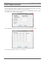
Part Program execution ............................................................................................................... 86
7.1
Part program execution .......................................................................................................................................................... 87
7.1.1
Selecting and activating a part program ................................................................................................... 87
7.1.2
Automatic execution ................................................................................................................................. 87
7.1.3
Block-by-block execution .......................................................................................................................... 87
7.1.4
Multiblock retrace..................................................................................................................................... 88
7.2
Executing blocks from the keyboard ................................................................................................................................... 89
7.2.1
MDI execution without an active part program ....................................................................................... 89
7.2.2
MDI execution with an active part program ............................................................................................. 89
7.2.3
Executing part of a part program .............................................................................................................. 90
7.3
Modifying blocks in BLK/BLK mode..................................................................................................................................... 90
7.4
Strings search ............................................................................................................................................................................. 91
7.5
Feedrate Override .................................................................................................................................................................... 91
7.6
Spindle feedrate override ....................................................................................................................................................... 91
7.7
Rapid Feedrate Override ........................................................................................................................................................ 92
7.8
Execution in Dry Run mode .................................................................................................................................................... 92
7.9
Memory Search ......................................................................................................................................................................... 92
7.9.1
Automatic Search ...................................................................................................................................... 93
7.9.2
Search for a pre-set block ......................................................................................................................... 93
7.10
Restart a working cycle ........................................................................................................................................................... 94
7.11
Searching Mode ......................................................................................................................................................................... 94
8.
Using Tables .................................................................................................................................. 96
8.1
Enabling Table Editor ............................................................................................................................................................... 96
8.2
Origin Table ............................................................................................................................................................................. 102
8.3
Tool Table ................................................................................................................................................................................ 104
8.4
Tool Offset Table ................................................................................................................................................................... 106
8.5
User Table ................................................................................................................................................................................ 110
45004602H
5
Prima Electro S.p.A.
9.
OPENcontrol – End User Manual
The Table Builder ....................................................................................................................... 111
9.1
General ...................................................................................................................................................................................... 111
9.2
Origin table customization ................................................................................................................................................... 114
9.3
Tool Table customization ..................................................................................................................................................... 119
9.4
Table Offset Customization ................................................................................................................................................. 124
9.5
User Table customization ..................................................................................................................................................... 129
9.6
Translation of the variable names....................................................................................................................................... 136
9.7
Configuration file .................................................................................................................................................................... 137
10.
Tool Management ...................................................................................................................... 138
10.1
General ...................................................................................................................................................................................... 138
10.2
Tool Pre-setting ...................................................................................................................................................................... 138
10.2.1
Manual Tool pre-setting ......................................................................................................................... 138
10.2.2
Manual pre-setting of the tool length mounted on the spindle ............................................................. 141
10.2.3
Automatic pre-setting of the tool mounted in the spindle ..................................................................... 142
11.
Machine Plot ............................................................................................................................... 143
11.1
General ...................................................................................................................................................................................... 143
11.2
Machine Plot Interface ........................................................................................................................................................... 143
11.3
Machine Plot Configuration ................................................................................................................................................. 147
11.4
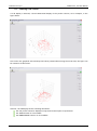
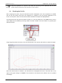
Profile Drawing ....................................................................................................................................................................... 151
11.5
Drawing a 3D Profile ............................................................................................................................................................. 153
11.6
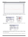
Checking the Profile ............................................................................................................................................................... 154
11.7
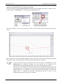
Drawing the disconnected axes profile (DRY RUN) .................................................................................................... 157
12.
System History ............................................................................................................................ 158
12.1
General ...................................................................................................................................................................................... 158
12.2
System History Interface ...................................................................................................................................................... 158
13.
13.1
Appendix A .................................................................................................................................. 164
Error Messages ........................................................................................................................................................................ 164
45004602H
6
Prima Electro S.p.A.
OPENcontrol – End User Manual
1. Features and specifications
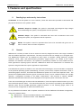
1.1
Reading keys and security instructions
ATTENTION! To use the system in a correct manner, follow the instructions provided in this manual and
pay special attention to the symbols below:
WARNING! Dangerous Voltage: This symbol is associated with dangerous high voltages
that could damage the system, the equipment and the operators.
WARNING! Danger: This symbol is associated with facts and circumstances that could
damage the system, the equipment and the operators.
NOTES: This symbol is used for operations that have to be executed with great care in
order to ensure their successful completion.
1.2
General
OPENcontrol is a family of state-of-the-art numerical controls, designed to meet a vast range of standard
and non-standard application requirements. The most powerful model can manage up to 64 digital axes.
The OPENcontrol systems can be installed on many types of machine: milling machines, grinding
machines, wood-, glass- and marble-working machines, oxygen cutters, etc. Thanks to the “open”
Hardware and Software architecture, the systems are particularly suitable for both standard and for
those applications requiring special functions. OPENcontrol allows the manufacturer to customize the
system to integrate with their specific application requirements.
The OPENcontrol systems are based on the most advanced technologies; from the hardware components
to the powerful Operating System (multitasking, real time, event driven) complete with either a local or
networked graphic interface, that makes the OPENcontrol system one of the most important CNCs. The
powerful and sophisticated functions typical of numerical control, can be combined with a user friendly
interface, configurable according to the MTB’s requirements. This interface is named “WinNBI”
(Windows Network Based Interface) and is displayed on the operator panel connected to the CNC.
There are several HMI types to match with the OPENcontrol, from the simple industrial monitor up to the
more advanced Operator Panel. This manual describes the user interface provided by the OPENconsole
Operator panel and the WinNBI application graphical software. In the following pages, there is an
overview of the configuration to which this manual refers.
For any additional information and a complete evaluation of all the OPENcontrol hardware configuration,
refer to the manuals below:
“OPENcontrol – Software Installation Manual” code 45006692G.
“OPENcontrol – Installation Guide” code 45006652F.
45004602H
7
Prima Electro S.p.A.
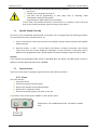
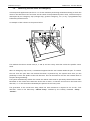
1.3
OPENcontrol – End User Manual
Hardware structure
The OPENcontrol systems are made up of a number of modules that can be combined in different ways
according to the requirements. Usually, the system has an operator panel used to display the data and to
handle commands to be sent to the CNC.
Only skilled operators together with the MTB can open the operator panel and the basic
unit for “service” reasons.
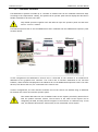
This manual explains how to use the OPENcontrol CNCs combined with the OPENconsole operator panel
as shown below.
In this configuration the OPENcontrol Control Unit is connected on the network to an industrial PC
dedicated to the graphical user interface. The control unit is therefore dedicated to the real-time
software, while the data is displayed on the industrial PC on the OPENconsole Operator Panel. The other
devices, such drives and I/Os, are connected to the Control Unit.
In other configurations, the user interface software runs on the control unit without using an industrial
PC between the control unit and the operator panel.
This manual describes the use of standard video screen layouts provided by Prima Electro
with the product software release. The structure of the video screen layouts can be
changed by the MTB, and may therefore appear to the end user in a different way. In this
case, the MTB will describe the functionality of the customized screen layouts.
45004602H
8
Prima Electro S.p.A.
OPENcontrol – End User Manual
1.3.1 Operator Panel
The Operator Panel (or front panel) is the interface device between the system and the operator.
In all versions, the Operator Panel is equipped with a LCD monitor, a standard USA-ASCII keyboard with
function buttons that work as softkeys.
It offers the most up to date Man-Machine interface techniques together with ease of use, its main
functions are:
introduction of operating commands.
introduction of start, stop and reset commands.
the data input using the keyboard
software and data entry (part program, software options, etc.), using USB connected devices.
display of the data and all the system operating conditions.
control of the CNC and PC ambient.
This manual deals with the OPENconsole operator panel use and the WinNBI graphical user interface by
Prima Electro.
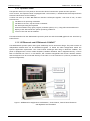
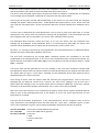
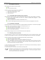
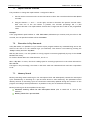
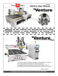
1.3.2 OPENconsole and OPENconsole COMPACT
The OPENconsole operator panel offers great modularity and an innovative design. The panel consists of
independent modules that can be assembled together to obtain the ideal configuration match the
specific application requirement. The Control Panel exchanges data using an EtherCAT fieldbus. The
panel is equipped with a silicon rubber keyboard, Windows standard, that is supplemented by a Touch
Pad or Track-Ball unit. The 17” or 19” Monitor, has a resistive integrated Touch Screen. Both the monitor
and the keyboard can be connected directly to the CNC or to the interface PC (if this is provided in the
system configuration).
Figure 1: OPENconsole configuration with Monitor, Control Panel, Control Panel Extension
and Keyboard with TouchPad
45004602H
9
Prima Electro S.p.A.
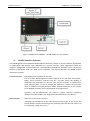
OPENcontrol – End User Manual
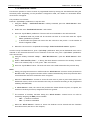
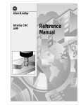
Figure 2: OPENconsole COMPACT - all HMI elements in one module
1.4
WinNBI Interface Software
The WinNBI graphics suite (Windows Network Based Interface) consists of several different applications
or independent HMI utilities, each dedicated to a specific function. These applications allow the
complete management of the machine tool. The applications (standard or optional) are for users having
different requirements (end user, MTB, service engineer). This manual describes the WinNBI utilities
used by the end user:
ProcessController
Data display and commands for the CNC.
This is the main WinNBI application which displays all the CNC data: axes position,
speed, active functions, program lines etc. and also allows the sending of
commands and parameters to the CNC. The Process Controller is supplied with
some standard video screens to manage the machine in manual and automatic
mode. In addition the optional Layout Builder ambient allows the screen content
to be adapted to suit the exact requirements of the application
Therefore, the ProcessController can present a graphic interface completely
different from the standard one supplied and documented by Prima Electro.
BootController
45004602H
Numerical Control boot controller.
It displays the messages from the CNC during the boot stage. It also allows the
system software restart and setting of the operating state that the CNC must be in
for machining, tuning and service.
10
Prima Electro S.p.A.
OPENcontrol – End User Manual
TableEditor
Data table editor
It allows display, entry and modification of some parameters, in particular:
origins
tools
tool offsets
user tables
tool magazines
tool data base
The TableBuilder is part of the TableEditor allowing customisation of the data and
the data display within the same tables. For details see chapters 8 and 9.
System History
This is a standard feature that stores in a file all the diagnostic messages produced
by the system in case of malfunction or incorrect operation, together with time
and date. It is a useful tool for fault diagnosis.
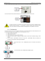
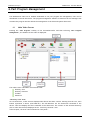
1.4.1 Connection between the WinNBI and the CNC
As described in the previous paragraphs, the WinNBI applications can be installed on both the PC
dedicated to the HMI and the control unit. In both cases, the applications connect to a data server in the
control unit. The connection between the WinNBI Application and the NC, is always done via the
network. The network will be virtual for the WinNBI locally installed on the CNC and real in case of the
PC installation on the network. In all the WinNBI applications, the user can select the numerical control
to which the application has to connect. The connection status is displayed in a dedicated status bar.
45004602H
11
Prima Electro S.p.A.
OPENcontrol – End User Manual
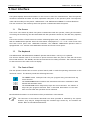
1.4.2 Common features of the WinNBI applications
Even if activated separately, the WinNBI applications are designed to offer the same graphic structure
and common elements for ease of use. The basic graphic structure of a WinNBI application is as follows:
Title bar:
Shows the name of the application and in some cases the name of the document
(typically the file name) to which the application refers for the data display.
Menu Bar:
Contains the main menu commands. These commands open a scroll-down menu
listing a group of commands or a data insertion panel. The menu bar always
contains all the entries in the Softkey bar together with other entries less used by
the operator.
Tool Bar:
Contains the buttons enabling the most used application functions. These can be
direct or indirect commands. Every WinNBI application can have several or nontoolbars.
Status Bar:
Displays the name of the Numerical Control to which the application is connected
and the connection status via the virtual or real network.
Data view area:
This is the area where the application displays the information and the graphic
objects dedicated to the specific functions required by the application. Each
WinNBI application has data and control elements of different types in this area.
45004602H
12
Prima Electro S.p.A.
Softkey bar:
OPENcontrol – End User Manual
It is a bar that, in all applications, has 5 buttons that can be enabled using the
mouse or touch Screen. For quicker activation, the buttons are associated with the
function buttons F6 and F10 of the operator panel keyboard. These 5 buttons open
the scroll-down menus containing the most used commands (see also Menu bar
description).
In some application, the display of the field described can be customized. Their presence on the video
depends on the settings made by the OEM and by the final user.
45004602H
13
Prima Electro S.p.A.
OPENcontrol – End User Manual
2. System Start-up
To turn the system on and off, comply with the machine manufacturer’s instructions. To
turn off the Numerical Control, follow the shut-down procedure described below.
2.1
System Power Up
The system is powered up when power is supplied to the central unit and the front panel, typically this is
done by operating the machine’s main power switch. Since most of the system software is stored on the
hard disk, all the software that remains resident for the numerical control operation is automatically
uploaded from the hard disk at system boot.
The BootController is a utility of the WinNBI graphic interface that checks and manages the CNC power
up. Using this application, it is possible to choose the CNC operating mode and to check the messages
generated by the CNC when powering up. The main working modes of the CNC are “Normal”,
“Emergency”, “Setup” and “Service” are defined as “stable”. Each mode has a specific function (for
details see the paragraph “Switching the system on in special operation modes”. The other modes, e.g.,
“HW boot” and “SW boot”, are transitory and lead to one of the stable modes. The BootController utility
displayed by the OPENconsole Operator Panel, in the Windows ambient, can be manually enabled or
automatically launched at power up. This behaviour depends on the choices made by the OEM when
installing WinNBI.
By default, the BootController, after connecting to the CNC and verifying that a stable mode has been
established, automatically launches the ProcessController application for the system management.
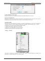
2.2
System Shut Down
The CNC must always be shut down using the “Controlled shut down” procedure that closes all open
sessions. This ensures the integrity of the data contained in the user, OEM or system files that, when
shutting down, could still be open for writing.
Controlled shut down can be initiated during all working stable modes of the CNC. It is done using the
BootController application.
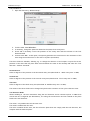
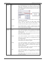
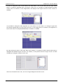
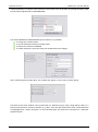
The procedure is:
With the system on in one of the four stable operating modes:
If disabled, enable the BootController application
45004602H
14
Prima Electro S.p.A.
OPENcontrol – End User Manual
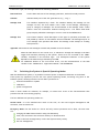
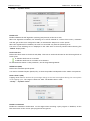
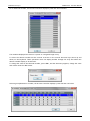
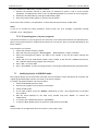
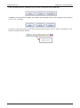
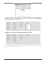
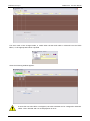
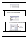
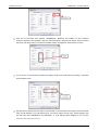
and select the “Shut Down” command from the “Boot” menu.
In the window, select the “Shut Down” command and confirm with the “OK” button
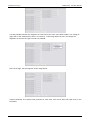
when shut-down is completed, the following message appears, indicating that the CNC can be turned
off.
45004602H
15
Prima Electro S.p.A.
2.3
OPENcontrol – End User Manual
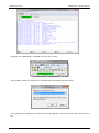
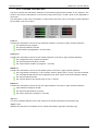
Diagnostic Screens
The control starts the diagnostic phase at boot up during which the hardware and software modules of
the system are checked. The modules are tested in the following order:
basic hardware (CPU, ROM, RAM, keyboard and disk)
modules and additional devices
numerical control software
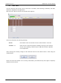
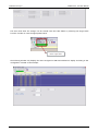
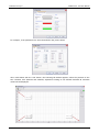
The messages generated from the CNC diagnostics are displayed in the main window of the
BootController application (Data Logger Display).
If the system is powering up, the messages are displayed as they are generated, but the same messages
are recorded by the CNC and are visible in the Data Logger Display at any time, even when the boot
phase of the CNC is finished.
The messages generated by the diagnostics are listed according to the test results and change according
to the hardware and software system configuration, both in quantity and meaning.
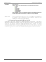
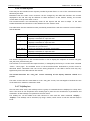
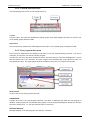
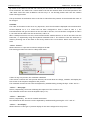
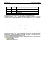
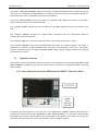
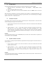
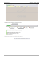
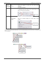
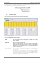
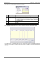
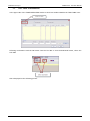
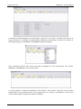
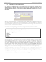
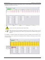
Usually the messages are divided in several parts as the example below:
45004602H
16
Prima Electro S.p.A.
OPENcontrol – End User Manual
From left to right, the message contains the following elements:
Date and Time
Are the date and time of the message generation, with mill-second precision.
Ambient
Indicates what part of the CNC generates it (e.g., “Log”).
Message Code
Two numbers separated by a slash. The numbers identify the message (in this
example "31/34"). The first number is the "Class" of the message, identifying a
group or category of messages. The second number is the message "Code". Codes
within a class are consecutive numbers starting from 1. The whole Class+Code
group uniquely identifies a message or an error code of the OPENcontrol.
Message Text
This column contains a brief description of the type of operation performed, the
test passed by a device or the software section initialized. The message may be an
error message if the operation has failed. The message in this example is "Loading
field protocols."
Appendix A describes all the messages in detail and possible corrective actions.
When the CNC detects a non-critical error, it indicates it through the message in the Data
Logger and continues powering up the system. These errors are recorded in the “SW0”
variable, accessible to the machine logic. The subsequent behaviour of the system
depends on the machine logic defined by the OEM.
For additional details on the non-critical errors, see the documentation of the SW0
variable in the “OPENcontrol – Application Manual” code 45006962W.
2.4
Switching the System in Special Operating Modes
With the OPENcontrol system, it is possible to execute power on sequences different to the default.
These power up sequences put the CNC into special operating modes, activating only parts of the
software system, allowing execution of such basic operations as:
software installation or update
calibration
system configuration
Some of these modes are essential, for example, to remove user errors in the characterisation that
prevents the CNC from starting properly.
The four OPENcontrol operating modes are:
Normal Mode: it is the standard boot mode of the CNC, for the Part Program management and
execution, axes movement etc.
Emergency Mode: the CNC works as a Server and only certain operations can be done, the main ones
are:
changing the AMP characterization using the ODM utility
reset, save and restore the retentive memory via BootController
reset of the CNC message history via the CNC System History utility
CNC file management
45004602H
17
Prima Electro S.p.A.
OPENcontrol – End User Manual
Setup Mode: the CNC works as a File Server. In this mode, using the Security application, it is possible to
upload the basic software, fixup or options to the CNC. It is also possible to save the CNC mass memory,
to manage the security levels and option enabling (PAK) and to manage surface checks of the CNC disks,
etc.
Service Mode: the CNC executes only the first boot stage of the CNC to initialize the axes control
software. This mode is used for the calibration of the digital drives via the ODM utility.
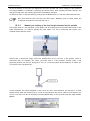
The Emergency, Setup and Service modes can be set only via the BootController utility. If nothing is
done with the BootController, the CNC will automatically select Normal mode.
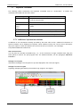
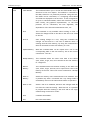
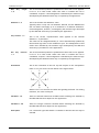
All the WinNBI application indicate the operating mode of the CNC via a status bar that displays the
name of the numerical control connected:
The background of the field containing the CNC name changes according to the status of the connection
between the WinNBI and the CNC. The colours used and their meanings are:
RED
CNC not connected. Connection in progress.
GREEN
CNC connected. CNC in “Normal” mode
ORANGE
CNC connected. CNC in “emergency” mode
BLUE
CNC connected. CNC in “Setup” mode
CYAN
CNC connected. CNC in “Service” mode
At the end of the CNC boot phase, in the working mode Normal or Emergency, if the option A03 is
enabled on the system (see Application Security WinNBI), the BootController automatically starts the
ProcessController application.
The ProcessController is the main application for numerical control management. The automatic start-up
of ProcessController can be disabled via the "NBIconfig" configurator of the WinNBI.
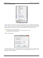
2.5
Selection of the Operating Mode
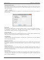
To select the boot-up operating mode of the CNC, the BootController is used. The procedure is the same
for all the operating modes described in the previous paragraph.
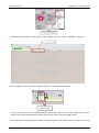
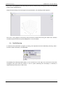
Selection of the operating mode with system on
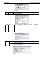
To enable an operating mode, i.e., Emergency, select “Emergency” using the “Mode” menu
45004602H
18
Prima Electro S.p.A.
OPENcontrol – End User Manual
or with the dedicated button in the BootController toolbar.
After selection, reboot the CNC using the “Shut Down” command from the “Boot” menu entry.
The system re-executes the boot phase, as if it had been turned off and on, and enters the EMERGENCY
boot mode identified by the orange colour in the status bar.
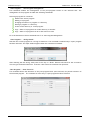
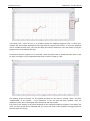
Selection of the operating mode with the system off
Turn the system on. After the first hardware boot stage, the CNC waits for 30 seconds, for the selection
of the operating mode from the Boot Controller. During this time it is possible, to select the desired
mode using the buttons on the tool-bar. The CNC will continue the boot with the selected mode. If no
selection is made, the CNC, continues to the Normal mode.
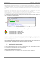
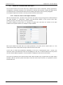
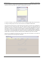
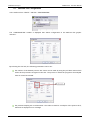
When the BootController is connected to a CNC waiting for the selection of the operating mode, the
following page is displayed:
45004602H
19
Prima Electro S.p.A.
OPENcontrol – End User Manual
In emergency status the following WinNBI applications can be used:
SECURITY
Manages the security levels of the system for different user and installation levels. More
information about this utility can be found later in this manual.
SYSTEM HISTORY
Utility for viewing / printing / deleting of the archived errors and system messages displayed
during the machine operation.
FILEBROWSER
Management of the CNC’s and the PCs OSAI file system.
ODM
Definition and change of the system configuration.
TABLE EDITOR
Management of the system’s data tables (Tools, Offset, Origins and User). In Emergency mode, it
is possible to work only on the tables file, not on the retentive memory files.
45004602H
20
Prima Electro S.p.A.
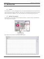
OPENcontrol – End User Manual
3. User Interface
The system displays data and information on the screen to start the communication, then the operator
introduces commands and data. All these operations take place on the operator panel. The keyboard,
video and the softkeys of the panels " OPENconsole " and "OPENconsole COMPACT" are described here.
The user interface is the means by which the operator communicates with the system.
3.1
The Screen
The screen is the means by which the system communicates with the operator, sharing all information
concerning the functioning, the data associated with the operations carried out, the data entry requests,
etc.
The screen can have a Touch functions to select field and graphic areas, to enable commands, etc.
With the OPENconsole Operator Panel the information is displayed on a 17” or 19” colour screen with
the Touch Screen option and 1280x1024 resolution. The COMPACT OPENconsole Operator Panel is
equipped with a 15’’ monitor with 1280x1024 resolution and Touch Screen option.
3.2
The Keyboard
The OPENconsole and OPENconsole COMPACT Operator Panels have a 101-key U.S. keyboard.
The function buttons from F5 to F10 have a special function when the panel is used with the Prima
Electro HMI software. The WinNBI, uses the function buttons for softkey activation. The F4 button is used
for the selection of the video screen to display.
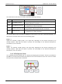
3.3
The Control Panel
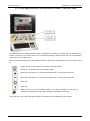
The two Operator Panels have a section (Control Panel) used to send the operating instructions to the
numerical control. The buttons provide the following functions:
The RESET button interrupts both the part program being executed and any
active function.
The CYCLE START button initiates axes movements and other commands in both
manual and automatic mode.
The CYCLE STOP button temporarily stops the active functions. For instance it
stops the part program execution with a controlled deceleration of the axes.
After a CYCLE STOP the operation can be restarted.
More detailed information on each button will be provided later in this manual.
The functions of the buttons described here those provided as standard by the system.
However, they may be changed through the machine logic written by the machine tool
builder. Refer to the MTB documentation.
45004602H
21
Prima Electro S.p.A.
3.4
OPENcontrol – End User Manual
The ProcessController
The ProcessController utility of the WinNBI displays and manages both axes movements and part
programming of the CNC. For general features of the WinNBI applications, refer to Ch.1-“Features and
specifications”.
For proper use of the ProcessController, it is important to understand the concept of “process”.
“Process” (or “channel”) means the management of a machine tool, i.e., the control of the axes, the
part program execution, the enabling and disabling of the machine logic control, etc.
More generally, process can also refer to a support activity for the machine tool, such as the tool
change, management of part loading and unloading, calculations, statistics, reports, etc.
The term multiprocess represents one of the most important features of the OPENcontrol numerical
controls. A single CNC can manage un to 24 different processes. The processes work simultaneously,
each executing a part program independent of the others. If the systems controlled by the individual
processes must be synchronized, they can be controlled more quickly and with greater flexibility than
with separate control systems. The standard screens provided by Prima Electro with the
ProcessController, display the data of only one process, so that they can be used on any machine. The
standard screen can be used for multiprocess/mono-process systems. For the multiprocess systems, it is
enough to select the desired process to ensure that the data on the screens are automatically updated
with the selected process.
This manual describes the use of the standard screens provided by Prima Electro the
software product release. The layout of the screens can be changed by the OEM and can
then appear in a very different way to the end user. In this case the OEM describes the
functionality of the customised screens.
Even if the content of the screen changes, the commands and the data-entry enabled with the data
entry menu or with the softkeys remains unchanged.
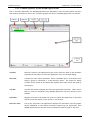
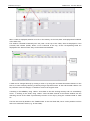
The picture below identifies the main part of the ProcessController screen
45004602H
22
Prima Electro S.p.A.
OPENcontrol – End User Manual
3.4.1 Title bar
Shows the name of the application and the name of the selected screen. The title bar can be hidden or
restored with the menu command “Display”-“Toolbar”.
3.4.2 Menu bar
Contains the main menu items, each item includes a set of commands displayed in a drop-down menu.
The items in the drop-down menu typically open a panel for the introduction of commands and
parameters. The most frequently used menu items are repeated in the Softkey task bar. The menu bar
can be hidden with the menu command "Display" - "Menu". To re-display the menu, press the keys "Ctrl"
and "M" on the keyboard.
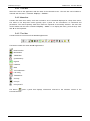
3.4.3 Tool bar
Contains buttons to activate all the WinNBI applications:
The buttons enable the other WinNBI applications:
BootController
MachinePlot
TableEditor
SystemHistory
Digicad
PathView
ODM
Tool Calibration.
I/O config
TimeMonitor
Security
O-Scope
O-Scope.NET
The button
opens a panel that displays information referred to the software version of the
ProcessController.
45004602H
23
Prima Electro S.p.A.
OPENcontrol – End User Manual
3.4.4 Operator Panel bar
It is a bar with buttons to select the CNC operating mode and the feedrate and spindle override values.
Mode selection
The CNC has different modes of operation, to move the axes in both manual and programmed mode. The
operator panel allows the mode selection.
All the buttons select only the desired mode, without starting any machine movement. The machine
movements must be confirmed with a dedicated command, usually the Cycle Start button.
Code
Mode
Use
MDI
Opens the MDI (Manual Data Input) data entry to allow
keyboard entry of a program block.
AUTO
Selects the continuous execution mode of the selected part
program.
BLK/BLK
Selects the block to block execution mode for the selected part
program
MANJOG
Enables continuous manual movements. Pressing the [CYCLE
START] button, starts the movement of the selected axis, The
movement stops when the Cycle Star button is released. For
details, see Ch. 5 “Axes jogging and Stop functions”.
JOG INCR
Enables incremental manual movements. Pressing the [CYCLE
START] button, the incremental movement defined for the
selected axis starts. For details, see Ch. 5 “Axes jogging and
Stop functions”.
PROFILE
Enables the return to the profile after a manual movement. For
details, see Ch. 5 “Axes jogging and Stop functions”.
HOME
Enables axes homing
HANDWHEEL
Enables management of the handwheel
The selected mode is displayed on the screen in the “CNC status” area. See the description of the main
video screen in following pages.
Selector and switches to change the override values
In the toolbar, are the override selector (percentage increase/decrease) and the buttons “+” and “-“ to
change the value of the selected override.
Using the override selector it is possible to select the type of override that will be changed with the “+”
and “-“ buttons.
45004602H
24
Prima Electro S.p.A.
OPENcontrol – End User Manual
The codes listed in the selector override values have following meanings.
Code
Definition
Use
FRO
Feed Rate Override
Percentage change in the cutting feed defined by Part
Program with the "F" function.
FMO
Feed Manual Override
Percentage change in the feed defined in the AMP
configuration for manual operations.
SSO
Spindle Speed Override
Percentage change in the rotational feed of the spindle
programmed by Part Program with the "S" function.
RAP
RAPid override
Percentage change in the feed defined in the AMP
configuration for rapid movements.
The current values of the override are displayed on the screen in the area “Feed and Overrides”. See
description of the main video screen in the following pages.
Button “+”
Adjusts the feedrate, spindle speed or the rapid feed, depending on the function selected by the
override selector. Each time the button is pressed, the percentage of the selected feed/speed is
increased by a pre-set amount.
Button “-”
Adjusts the feedrate, spindle speed or the rapid feed, depending on the function selected by the
override selector. Each time the button is pressed, the percentage of the selected feed/speed is
decreased by a pre-set amount.
3.4.5 OEM Operator Panel
It is a password-protected button bar, for starting and stopping the movement. This bar is provided for
the OEM only to allow initial machine tests which do not involve movement of the axes. The bar contains
the Cycle Start, Hold and Reset commands.
45004602H
25
Prima Electro S.p.A.
OPENcontrol – End User Manual
3.4.6 Screen layouts
These may be the standard screen layouts provided by Prima Electro or one of the customised screens
defined by the OEM.
Remember that the video screen structure can be changed by the OEM and therefore the screens
displayed to the end user may be different to those described in this manual. Usually, the screens
contain data of the process under control.
The ProcessController can automatically resize all the objects and the texts to adapt to the main
window dimensions and therefore to the dimensions of the monitor used.
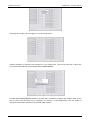
The table below lists the standard screens provided by Prima Electro with the numerical control software
and the WinNBI.
File name
Screen description
osai_p6a.qv
Screen to manage program execution.
Displays a maximum of 6 process axes.
osai_p9a.qv
Screen to manage the program execution
Displays a maximum of 9 process axes.
osai_a5a.qv
Screen to manage the programs in automatic. Displays a
maximum of 5 process axes.
osai_a9a.qv
Screen to manage the programs in automatic.
Displays a maximum of 9 process axes.
osai_m9a.qv
Screen to manage up to 9 axes in manual mode
osai_aux.qv
Screen to manage the auxiliary axes of the machine logic
The default configuration of the ProcessController is set to display the sequence of screens osai_p6a,
osai_a5a, osai_m9a and osai_aux.
The selection of a screen with the sequence above, is managed by the F4 key or via the menu command
“Select – Next page”. The standard screen of the ProcessController dedicated to process control is
described below. Remember that the screen setting depends on the OEM’s choices and may vary
significantly from those described in this manual.
This manual describes the “osai_p6a” screen containing all the display elements related to a
process.
The other screens show the same data as in the “osai_p6a” screen, but rearranged to facilitate the use
of the machine in manual or automatic mode.
3.4.7 SoftKey bar
Like the main menu items, each softkey selects a group of commands that are displayed in a drop down
menu. The items in the drop-down menu usually open a panel for the introduction of parameters and
commands. All the softkeys are repeated in the main menu.
The softkey bar can be hidden from and restored to view with the menu command “Display” –
“Softkey”. The softkeys can be activated, by using a mouse, touch screen or with the function keys F5
to F9.
45004602H
26
Prima Electro S.p.A.
OPENcontrol – End User Manual
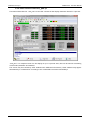
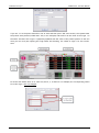
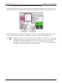
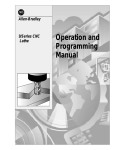
3.4.8 Main video screen osai_p6a.qv
This manual describes the “osai_p6a” screen that contains all the display elements related to a process.
“osai_p6a” is a complete screen for the display of up to 6 process axes, that can be used for machining
in all modes (automatic and manual).
The screen may be overlaid by other windows with additional information, these windows may appear
automatically or on demand or according to user commands from menus and softkeys.
45004602H
27
Prima Electro S.p.A.
OPENcontrol – End User Manual
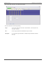
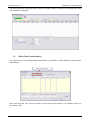
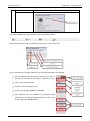
The osai_p6a screen has been divided into several functional areas, as shown in the following figure.
3.5
CNC Status Area
The Status Area contains information referring to the operating status of the numerical control:
Field
Description
CNC
Name of the Numerical Control connected on the network. The data
displayed on the screen are referred to this NC.
PROCESS
Displays the number of the process selected and being controlled.
MODE
Displays the current operating mode, which can be either Automatic or
Manual. The following belong to the modes:
Automatic: AUTO, BLK/BLK, MDI
Manual: JOG CONT, HOME, JOG INCR, JOG RETURN, HANDWHEEL
STATUS
Displays the status of the currently selected process. Some are valid for both
Automatic and Manual modes, while others are possible in only one mode.
The possible states are: INPUT, ERROR, EMERG.
UNIT
Indicates the current unit of measurement for the selected process. It can be
mm (millimetres) or inches
45004602H
28
Prima Electro S.p.A.
OPENcontrol – End User Manual
Each of the aforementioned states is briefly described in the table. More detailed information will be
provided in the explanations of operator actions in which they are involved.
STATUS
AUTO
MAN
IDLE
The process is stopped waiting for a command.
IN CYCLE
The process is executing a part program or a command
entered from the keyboard in MDI mode.
The process is performing a manual movement.
RUN
CYCLE STOP
HOLD
RUNH
MEANING
The execution of a part program or a command provided
in MDI was stopped and the process is in a wait state.
The execution of a manual movement was interrupted
with CYCLE STOP button and the process is in a wait
state.
The process has been stopped during the execution of a
part program with CYCLE STOP. Switching the process in
MANUAL, the status changes from STOP to HOLD CYCLE.
If one or more axes are manually moved, during these
movements the message becomes RUNH and buttons
CYCLE START and CYCLE STOP are both turned on.
RUNH informs the user that there is an on-going
movement.
HRUN
With the process in the HOLD or CYCLE STOP state and
CYCLE STOP is pressed, the status switches to HRUN
which means that the process is ready to continue the
interrupted machining. The CYCLE STOP button will
turn off and the process waits for CYCLE START to be
pressed.
RESET
Indicates that the process is still managing the reset
command following pressing of the RESET button.
WAIT
The process is waiting to be synchronized with another
process.
Indicates that the process is waiting for a data input
from the keyboard (a data entry window is on the
screen).
Indicates that the process has detected an error during
operation. The error can stop the process or be managed
by the part program.
The system detected an anomaly, and operator
intervention is required. The type of fault is indicated
on the screen with an explanatory message explained in
the Appendix A ("Emergency Messages").
INPUT
ERROR
EMERG
45004602H
29
Prima Electro S.p.A.
3.6
OPENcontrol – End User Manual
Flags Area
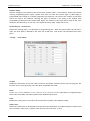
The active options referred to the current mode, are displayed in reverse in the flag area
Flag
Description
OSTOP
Optional Stop (Ready to stop when M01 occurs in the program)
BLK DEL
Block Delete (blocks preceded by / are omitted
DRY R
Dry Run Program executed without axis movement
RAP O
Rapid Override
Auto J
F Byp
Feed rate Bypass
Retr
Retrace
MemS
Search Memory
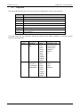
The table below lists (for Automatic and Manual mode) the sub-modes available, the possible process
status and the flags used.
45004602H
Mode
Sub-mode
Status
Flag
AUTO
BLK/BLK
MDI
IDLE
RUN
HOLD
HRUN
RUNH
WAIT
INPUT
EMERG
ERROR
RESET
OPTIONAL STOP
BLOCK DELETE
FEED BYPASS
RETRACE
RCM O
N
MANUAL
HOME
JOG INCR
JOG RETURN
HANDWHEEL
IDLE
RUN
HOLD
HRUN
RUNH
EMERG
ERROR
RESET
RETRACE
JOG+
JOGRCM ON
30
Prima Electro S.p.A.
OPENcontrol – End User Manual
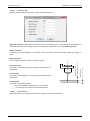
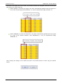
3.6.1 Axes positions and origin area
This area of the main screen displays the position data the origins of the process axes. The figure below
indicates the elements contained in the area. The data are arranged as a matrix where each line belongs
to the axis whose name is shown in the first column.
Axes name
The axis name is a letter identifying an axis within a process. Unlike a physical axis identifier, that is a
unique number in the system, the axis name can be repeated in another process.
The axis name in reverse indicates the axis selected for manual movements. The selection can be made
in different ways:
Clicking with the mouse on the axis name
Sequentially, via the command menu or softkey “Select” – “Next Axis”
By the Cursor Up/Down Keys
Sequentially, by pressing “Ctrl” and “A” simultaneously.
Axes position
The label of this column indicates the type of positions displayed in the fields below. The content of this
field changes according to the selection made by:
the softkey or menu command “Select” – “Positions”
Sequentially, from the keyboard by pressing the keys “Ctrl” and “B”.
The position types that can be displayed for the process axes are:
Work
position calculated with respect to the current origin
Machine
actual position calculated with respect to the current origin
To go
distance to go (difference between current and commanded position)
Error
following error, i.e. the difference between the positions Work and Machine.
Absolute
absolute position referred to the home position ignoring offsets & origins
The positions of the axes are displayed with 10 digits in the formats 7.3, 6.4 or 5.5 (where the first digit
represents the integers, the second the decimals) according to what has been configured in AMP for
each axis.
Programmed position
This is the last position programmed from part program or MDI command. It is 10-digits long, displayed in
the same format as the “Axis position” fields.
Selected Origin
Number and type of the origin selected for the axis. In this field are also displayed characters:
- “T” for temporary origins
- “I” for incremental origins
If only the origin is displayed, then the origin is absolute, not temporary or incremental.
45004602H
31
Prima Electro S.p.A.
OPENcontrol – End User Manual
3.6.2 Feed and overrides Area
This area contains the information related to the machining speed and movement of the machine. The
values in this area are expressed in current units of the process (mm / inches), which is also displayed on
the screen.
The information in this area is arranged in a matrix where the lines refer to the type of speed indicated
by the labels in the first column.
Feed line
Contains the information referred to the machining feedrate. From left to right, the data indicates:
The feedrate set by program
the selected feedrate override
actual feedrate (programmed * feed override)
Feed M line
Contains the information referred to the manual feedrate. From left to right, the data indicates:
the configured feed for manual movements
the selected manual feedrate override
the actual manual feedrate (configured * override)
SPEED line
Contains the information referred to the spindle speed. From left to right, the data indicates:
the programmed revolutions. If the Constant Surface Speed (CSS) is active, the field indicates
the calculated speed based on the programmed one which varies as the work diameter changes
the selected speed override
the override speed of the spindle (rpm or CSS) * override.
RAPID line
Contains the information referred to the axes rapid feedrate. From left to right, the data indicates:
rapid feedrate configured in AMP
the selected rapid feedrate override
the actual rapid rate (configured * override)
Jog field
It’s the incremental distance set for the execution of manual movements (incremental Jog).
Jog Dir. field
Indicates the direction of movement set for manual movements (Jog and incremental Jog).
45004602H
32
Prima Electro S.p.A.
OPENcontrol – End User Manual
3.6.3 Selected Tools Area
The area is dedicated to the display of the programmed tools.
Tool
Number of the tool mounted on the spindle and its active offset. The field contains 2 groups of digits
divided by a point. The group on the left of the point represents the tool number, the one on the right
the offset.
Next T
Number of the next tool and its associated offset that will be mounted in the spindle. This is the tool
already set by the program, but not yet mounted in the spindle.
The field contains 2 groups of digits divided by a point. The group on the left of the point represents the
tool number, the one on the right the offset.
Diam
Diameter of the tool mounted in the spindle.
Offs 1
Length 1 offset of the tool. The machine axis to which the tool compensation refers to in this field is
configured in AMP via the ODM application.
Offs 2
Length 2 offset of the tool. The machine axis to which the tool compensation refers to in this field is
configured in AMP via the ODM application.
Offs 3
Length 3 offset of the tool. The machine axis to which the tool compensation refers to in this field is
configured in AMP via the ODM application.
Offs 4
Length 4 offset of the tool. The machine axis to which the tool compensation refers to in this field is
configured in AMP via the ODM application.
Offs 5
Length 5 offset of the tool. The machine axis to which the tool compensation refers to in this field is
configured in AMP via the ODM application.
45004602H
33
Prima Electro S.p.A.
OPENcontrol – End User Manual
3.6.4 G and M functions Area
Area that displays the active G codes and M functions.
G codes
Active G codes. The codes are divided into display groups. Each field displays the active G code for one
of the modal groups defined in AMP.
M functions
Active M functions. Usually each field displays an M code for every modal group configured in AMP.
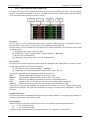
3.6.5 Part program data area
This is the area dedicated to the display of the lines of the part program being executed. The area is
read-only, at this point you cannot edit the program.
In order you will find, the block already executed, the block being in execution highlighted in reverse
and the blocks still to be executed. The part program lines automatically scroll upward as they are
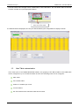
executed by the CNC. The figure below shows an example of the lines of a program in execution:
SELECTED PP
It’s the name of the main program selected.
SUBPROGRAM
Contains the name of the sub-program selected. The name is displayed only when the sub-program is
enabled. A sub-program can call another sub-program. The sub-program displayed is always the one with
the lower nesting level, i.e. the last called and still in execution.
PROGRAM MESSAGE
Messages defined in the part program with the DIS, command.
45004602H
34
Prima Electro S.p.A.
3.7
OPENcontrol – End User Manual
Keyboard Commands
The following tables summarizes the keyboard commands used as “accelerators” to enable the
commands associated with the menu items.
Flag
Description
F4
Sequential selection of the screens to be displayed from
a list of active screens
F5, F6, F7, F8 F9
Activation of the corresponding softkey
Ctrl + A,
key ↑,
key ↓
Sequential selection of the axis to be moved in manual
mode
Ctrl + B
Sequential selection of the axes position type
Ctrl + P
Sequential selection of the selected process
Ctrl + T
Sequential selection of the selected target (CNC)
3.7.1 Additional information windows
In addition to the information normally provided by the main video screen, additional information in
specific windows can be displayed as required. These windows overlay the current screen and appear
only upon request or when the system has to inform the user (for instance, via a message).
The possible additional windows are:
MDI Command Panel
It is the panel for the MDI commands entry, i.e., for the execution of single command lines using the
same syntax as used for the part program lines. For additional details, see the paragraph “MDI Panel
Functions ”
Messages from System
Information messages from the system or process displayed in four lines (see figure)
Messages from PLC Program
Signalling messages generated by the machine logic program. (see figure)
45004602H
35
Prima Electro S.p.A.
3.8
OPENcontrol – End User Manual
Panels for Command and data input
The ProcessController has several data entry windows used to enter commands, working parameters,
configuration, parameter setting for the movements in manual and automatic. Usually the data entries
are enabled by the commands associated with the softkeys described in the previous paragraphs.
This chapter explains the function of all the process Controller data entries.
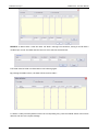
3.8.1 General rules on the input windows
With the standard screens, the data can be entered in the system only by using specific windows defined
as “input windows” or “data-entry”. usually, the data-entries appear in the current screen after
enabling an item in the main menu or with the softkey.
For proper handling of input data it is necessary to apply some rules that are common to all input
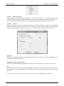
windows in the system. Below is an example of input window.
Each input window has fields that can contain parameters, file name, device names and so on. The
values entered must comply with the type and the format of the field.
In the case of fields with parameters depending on the unit of measurement (mm / inches), the
numerical values associated with them will be displayed in the unit of measure defined for the process
with the default AMP configuration. The information is displayed in the title of the window.
The cursor is positioned on the selected input field. When the data-entry is opened the first input field is
selected. With the operator panel touch-pad or with the touch-screen function, it is possible to select
the desired field.
45004602H
36
Prima Electro S.p.A.
OPENcontrol – End User Manual
The characters inserted via the keyboard are displayed on the screen as the cursor is moved. Data entry
can be managed using the following keys:
KEY
FUNCTION
Moves the cursor to the right or to the left inside the field.
CANC or DEL
Deletes the character to the right of the cursor.
Deletes the character to the left of the cursor.
Toggles between overwrite and insert modes..
TAB
Moves the cursor on the following field
Aborts the current data entry window.
Confirms the current data entry window.
The input window can be exited at any time. If the data is not confirmed, the values inserted are not
applied.
To exit the input window, cancelling the data entered, press "Cancel".
To exit the input window and validating the data entered, press "OK".
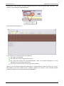
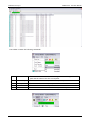
3.8.2 The ProcessController soft-keys
The ProcessController interface is controlled through the mouse or keyboard. To simplify access to all
the CNC commands through the keyboard, some special keys have been added at the bottom of the
application window, the soft-keys. The soft-keys are activated by pressing the OSAI Operator Panel F5,
F6, F7, F8, and F9 function keys, the Touch-pad mouse or the Touch-screen function
The soft-key activation opens a drop-down menu. To select the desired menu item from the keyboard
use the arrow keys (cursor up, cursor down).
All the commands available with the soft-keys are also present in the main menu.
The ProcessController soft-keys are the following:
45004602H
37
Prima Electro S.p.A.
OPENcontrol – End User Manual
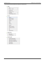
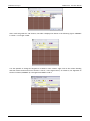
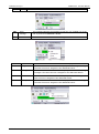
The drop-down menus opened by the softkeys are shown below:
Select
Set Up
Origin/Tool
PartProgram
45004602H
38
Prima Electro S.p.A.
OPENcontrol – End User Manual
Utility
The panels opened by the drop-down menu items are explained In the following pages.
“Select” – “CNC”
This command changes depending on the configuration of the type of connection (single or multiple).
The configuration is set using the configuration panel reserved for MTB use.
If the ProcessController has been configured for a single connection, the selection panel is as follows:
Permits selection of the CNC to be connected to the network.
When the WinNBI is connected to the CNC control unit, use the generic local address indicated by “IP.”
to address the local CNC. The remote CNCs are addressed by the prefix “IP.” followed by the TCP/IP
address of the control unit (as shown in the picture). By using the Offline button or writing NULL instead
of the CNC name it is possible to disconnect the CNC. This mode can be used by an offline PC in order to
use the Layout Builder only.
When the offline mode is active the ProcessController displays an empty screen layout.
In this condition ProcessController doesn’t try to connect to the selected CNC.
The "Remove" button is used to remove an unused name from the history of the CNC previously
connected. The key removes the selected name from the “CNC previously selected” list.
45004602H
39
Prima Electro S.p.A.
OPENcontrol – End User Manual
3.8.3 Multiple connection, CNC selection
Multiple connection permits a list of CNCs to be specified to be connected contemporaneously.
It is used and useful only when the screen layout has been designed to show the data of more than one
CNC at the same time.
If the ProcessController has been configured for multiple connections, the selection panel is as follows:
This panel is used to set the name of the selected list. The list contains the names of all the numerical
controls to be connected simultaneously. To select the offline mode write “NULL” in the field “CNC list
to select”.
The "Remove list" button may be used to delete an unused list (the button removes the selected name
from the list).
To define the content of the list, press Edit.
The list selected is the one shown in the "CNC list to be selected" box.
If the list does not exist yet, a new empty list is created.
The Edit button opens (and closes upon being clicked again) the dialog window dedicated to the
composition of the list. The dialog window can be edited as shown in the figure below:
45004602H
40
Prima Electro S.p.A.
OPENcontrol – End User Manual
By means of the "Remove selected CNC" button you can remove the selected CNC from the list of CNC’s
to be connected. The "Add to list " button adds to the list the network name of the CNC specified in the
"CNC name" field. The name is added to the list only if it not already present and if the list contains
fewer than eight names.
The Up and Down arrow buttons next to the list of CNCs allows the position of the selected CNC name to
be changed.
CAUTION:
The order of the names in the list is very important, since the information displayed in ProcessController
screens depends on it. If a screen box has been configured to show a value of CNC # 1, the
ProcessController will get the value from the first CNC in the list; if a box has been configured for CNC #
2, the value will be taken from the second CNC, and so on.
When a multiple selection is active, the ProcessController enables selection of one of the CNCs from the
status bar, or sequentially using the keyboard command CTRL+T. The selection from the status bar is
made by selecting one of the items in the list by means of the "Arrow down" button next to the "CNC"
field.
“Select – Process”
Allows selection of a process from those configured in AMP.
The existing processes are listed in a drop-down menu.
If there is only one process, the command is disabled.
If the screen is valid for the new process selected, the screen does not change, instead it will display the
first screen of the sequence assigned to the process.
The command can also be sent from the keyboard by simultaneously pressing the keys “CTRL” and “P”.
“Select” – “Next page”
Selects, sequentially, the screen following the sequence of the screens in use.
The command can be sent from the keyboard (key “F4”).
“Select” – “Next axis”
Selects, sequentially, the axis for manual movements.
the command can also be sent from the keyboard by simultaneously pressing the “Ctrl” and “A”.
“Select” – “Pos Display”
Allows selection of the type of position display for the axes configured in the process.
45004602H
41
Prima Electro S.p.A.
OPENcontrol – End User Manual
“Select” – “Next Pos Display”
Selects sequently the type of position display for the axes in the process. For each activation of the
command the position type display can be selected in the order Work, Machine, Absolute, To Go, Error.
The same command can be enabled from the keyboard by simultaneously pressing “Ctrl” and “B”.
“Set Up” - “Manual”
Opens a data entry window that allows the length of the axis movement to move with incremental
manual movments and the type of return after a manual movement. It also enables the tool extraction
procedure for some particular cases (see Chapter 6, " Manual Axes Movements and Stop Functions ").
Jog Value
Insert the incremental distance for incremental manual movement. The value inserted is displayed in the
JOG field of the main video screen.
Jog Return/Jog Incr mode Selection
Specifies the JOG RETURN and the JOG INCR modes, that can be automatic or manual (See Chapter 4)
Skip
Specifies whether to return to the profile from HOLD, or to position along a straight line to the end point
of the block in which the movement was suspended in HOLD. To skip a return on the profile, tick the
Skip field.
For the fields related to the “Tool Direction”, refer to Ch. 5 “Axes jogging and Stop functions”.
45004602H
42
Prima Electro S.p.A.
OPENcontrol – End User Manual
“Set Up” - “Dynamic Param”
Enables VFF
Enables/disables the VFF algorithm (velocity feed forvard) of the servo axes.
When the algorithm is enabled, the following error will be reduced to a value close to zero, consistent
with the gain of the servo configured in AMP, to minimize the shape error on the profile.
When the algorithm VFF is disabled, the axes are controlled only with the following error.
The value of the following error is displayed in the video area of the axis positions when selecting the
“ERROR” display mode.
Dwell time G04
Defines the dwell time at the block end (G04). This time is used with G04 and in the following blocks of
fixed cycles:
In G94 the dwell time is in seconds.
in G95 the dwell time is in number of revolutions.
For detailed information on this parameter, see the Programming Manual.
SPEED limit (RPM)
Defines the maximum spindle speed.
It is used in Constant Surface Speed (CSS), ie when the spindle feed depends on the master axis position.
Return feed % (G84)
Tapping return feed. It defines the percentage change in the feed rate applied during the return phase
of the tapping cycle. The range of values is 0-125%. The default value is 100%.
“Set Up” – “Dynamic Limits”
Enables Look-Ahead
Enables the automatic deceleration on the angles when executing a part program. If disabled, all the
DLA instructions of the current part program will be ignored.
45004602H
43
Prima Electro S.p.A.
OPENcontrol – End User Manual
Maximum Deviation Angle
MDA (Maximum Deviation Angle) is the maximum angular deviation from the axis in which G27 is active.
The selected angle is the operational limit for G27. Angular deviation greater than this angle is done by
G29 or point-by-point.
“Set Up” – “Program”
Opens a data entry that allows the configuration of some paraemters that influence the part programs
execution modes.
Block Delete
Enables the block delete feature, the block preceded by a slash "/" is NOT executed (equal to the DSB =
1 programming). At system boot, this field is set to the condition established in the AMP
characterization. System reset does not change the previous setting.
Optional Stop (M01)
Enables the optional program stop. At system boot, this field is set to the condition established in the
AMP characterization. System reset does not change the previous setting.
Feedrate Bypass
It enables forcing of the rapid speed with G1, G2 or G3 active. At system boot, this field is disabled.
System reset disables this field.
Rapid Override Control
Enables control of the rapid feed precentage with the Operator Panel. At system boot, this field is set to
the condition established in the AMP characterization. System reset does not change the previous
setting.
Disable program scroll
Disables part program scroll in the AUTO mode. If scroll is disabled, the block execution is faster. At
system boot, this field is set to the condition established in the AMP characterization. System reset does
not change the previous setting.
Stock allowance
Defines the machining allowance value added to the tool radius for the calculation of the trajectory in
“tool offset” (G41 - G42) mode. It is the same as programming the MSA variable. At system boot and
after a reset, this parameter =0.
45004602H
44
Prima Electro S.p.A.
OPENcontrol – End User Manual
Rotation Angle
Defines, in degrees, the rotation of the active plane (positive value = CCW rotation). Unlike the triliteral
code by programming (ROT, angle), system reset does not reset the rotation angle. If (ROT angle) is
programmed after setting up a rotation angle with this input box, the value of the rotation of the plane
will be the sum of the rotations. Entering the angle of rotation of the plane in this window after
programming a value with the trilateral (ROT angle), the rotation of the plane will be equal to the value
entered in the data entry. In this case, the rotation preset by (ROT, angle) will be lost.
Horizontal axis – Vertical Axis
Defines the working plane. Ii is equivalent to programming G16. When the system starts-up and after a
reset, the work plane is defined by the value set in AMP (G17, G18, G19 or the alternative axis plane
(G16).
“Set Up” – “Axes Setup”
Locked
Enables the movement of the axes. When selected, the system normally execute the part program, but
the axes do not move physically. The reset does not disable this mode.
Mirror
Enable the reversal ("MIRROR") of the trajectory of the specified axis.It is equivalent to programming the
three-letter code (MIR, axis name).System reset disables this function.
Scale
Enables the scaling factor referred to the axis specified. System reset disables scaling..
Scale Factor
Defines the scale factor to be applied to the specified axis. Equivalent to programming the triliteral code
(SCF axis name, scale factor). System reset reset set the scale factor to zero.
45004602H
45
Prima Electro S.p.A.
OPENcontrol – End User Manual
“Setup” - “Probe Set Up”
Opens an input window for the entry of the probing parameters.
Approach tolerance. Represents the distance from the probing target. The probe moves this distance in
rapid and then starts the probing cycle at the feedrate programmed in the entry Measuring Feed.
Safety Tolerance.
A value that prevents damage to the probe. If the probe does not find the target within this range, it
stops.
Vertical Shift.
The value for the ordinate axis of the probe requalification in
millimetres.
Safety Tolerance
Horizontal Shift
The value for the abscissa axis of the probe requalification in
millimetres.
Approach Tolerance
Measuring Feed
The feed with the probe moves towards the target.
Probing Mode
The value of the probing mode:
0 for the standard probing (return to start point)
1 for the probe to remain at the probed position
“Setup” – “Set Accuracy”
Opens a data-entry to define the parameters related to circular interpolation.
45004602H
46
Prima Electro S.p.A.
OPENcontrol – End User Manual
Circular Endpoint Tolerance (CET)
Defines the tolerance for the difference between the initial and final arc of a circle.
Full Circle Threshold (FCT)
Determines a tolerance for the distance between the first and the last point of the arc of the circle. If
the distance is less than the value of FCT, the arc is to be considered a full circle.
Arc Modality (ARM)
Determines the mode applied by the system to normalize a programmed arc with center coordinates (I,
J) and the end point, in order to make it geometrically congruent. The valid values are 0, 1, 2 and 3.
0 displaces centre within the CET tolerance (default mode)
1 displaces starting point within the CET tolerance
2 displaces centre independent of the CET tolerance
3 displaces centre beyond the CET tolerance range
“Set Up” – “Dry Run”
If Dry Run is selected it is possible to test the part program execution without any physical axis
movement or command being sent to the machine logic.
45004602H
47
Prima Electro S.p.A.
OPENcontrol – End User Manual
“Set Up” – “Search in Memory”
Search in memory: is the search for point in the program where it was interrupted and the subsequent
recovery cycle or the search for a block where processing will begin. The parameters that uniquely
identify a interrupt at run time are stored and continuously updated during the execution of the
program. Based on these parameters, the control has the ability to perform an automatic search.
The strored search can be done in two ways:
Stored search of the interruption block (following a shutdown or reset).
Stored search of to a specific block
“Set Up” – “Block Retrace”
This function allows blocks to be executed backwards with axis movements in reverse along the profile
previously executed. The number of blocks that can be executed backwards may vary from 1 to 64,
depending on the AMP configuration.
45004602H
48
Prima Electro S.p.A.
OPENcontrol – End User Manual
The sequence of the operations to execute the commands backwards is:
Stop the running program by pressing Cycle Stop.
Activate Block Retrace through the data-entry.
Press the "Cycle Start" key: the system moves the axes backwards along the path stored during
the program execution..
The movements will be executed in selected mode (AUTO, BLK / BLK).
Execution of Block Retrace can be interrupted by pressing the Cycle Stop command.
To return to the standard conditions, disable Block Retrace, release Cycle Stop and press Cycle
Start.
MBR Length
This field defines the maximum distance that can be run backwards. By pressing Cycle Start, the control
runs backward, along the profile, for a distance equal to the value set.
MBR Threshold
Allows the definition of a distance threshold from an edge. If the reverse displacement moves the tool
along the profile close to one edge, the control recalculates the end point along the profile to keep
(before or after the corner) the minimum distance defined with this field.
“Set Up” – “Ref”
Opens an input window allowing virtual referencing of the axes.
The box references the axes at the position where they are. Select the axes to refer and confirm by
clicking “OK”.
The axes referenced in this way, unlike the HOME cycle, is only a logical operation for which
the parameters NULL OFFSET and HOME POSITION, configured in AMP for each axis, are not
considered and the operating limits are referred to the point where the axes are upon
confirmation.
“Date” and “Time”
Opens a box that allows the CNC date and time to be changed.
45004602H
49
Prima Electro S.p.A.
OPENcontrol – End User Manual
“Origin/Tool” – “Origin preset”
Opens an input window to define the origin values.
Origin Number
Number of the origin whose values are to be modified
Origin Values
Values of the axes to which the origin refers
”Origin/Tool” – Tool offset preset”
Opens a data-entry that allows the definition of an tool length offset
Offset Number
Offset number of the selected tool
Reference Axis
Name of the spindle axis (usually Z)
Tool Tip Position
Distance between the spindle "nose" and the fixed reference point
“Part Program” – “Activate Part Program”
Selects a part program for execution
“Part Program” – “Deactivate Part Program”
Disables the current part program.
45004602H
50
Prima Electro S.p.A.
OPENcontrol – End User Manual
“Part Program” – “Part Program management”
This command enables the management of the part-programs stored on the selected CNC. The
management of the programs includes the following commands:
Selecting a program for execution.
Deselect the active program
Editing of a program.
Changing the name of a program or a directory
Erasing a program or a directory.
Create a new directory or a new program.
Copy / Paste of a program from a CNC directory to another.
Copy / Paste of a program from PC to CNC and vice versa
For a full discussion of these commands see Ch. 6 "Part Program Management".
“Part Program” – “String Search”
Searches the current program for a string of characters. The command is enabled only if a part-program
has been selected. The input window appears when the command is initiated.
After inserting the text string; each press of the <Up> or <Down> buttons will search for the occurrence
of a string in the desired direction. Press the <OK> button to terminate the operation.
“Part Program” – “Exec From To”
This command allows the definition of the part-program block (start and end) for partial execution of
the selected program. The command is active only if a part program has been selected.
45004602H
51
Prima Electro S.p.A.
OPENcontrol – End User Manual
Allows setting of the partial execution modes of a part program; the number of parameters inserted
determines the mode:
From
To
Mode
Specified
Specified
Executes the part program between the specified blocks
Specified
Absent
Executes the part program from the block specified to the
end
Absent
Specified
Executes the part program from the current line to the
specified block
Absent
Absent
Executes from the current line to the end
The starting block is defined using only one of the possible selections defined at point 3.
The conditions, described at point 4, determining the end of the program execution, can be more than
one at the same time. The field $BRK identifies the equivalent variable used in the part programs, for
this field indicate the value that the variable must have in order to finish the program.
“Utility” – Application name
The “Utility” soft-key opens a drop-down menu that allows thw launch of the other WinNBI applications
listed below.
BootController, Machine Plot, TableEditor, SystemHistory, Digicad, PathView, ODM, Calibration Tool,
TimeMonitor, Security, O-Scope, O-Scope..NET, FileBrovser
The OEM can disable these applications using the NBIconfig application.
Utility - Variables
The “Utility” soft-key also allows the opening of a data-entry for the display and change of program and
system variables.
The variables are divided by class and may be used for part-program writing, to obtain data from the
system and from the machine logic developed by the OEM. The meaning of their content is therefore
bound by the application developed for machine tool in use.
For viewing and editing of the parameters through the windows of the standard ProcessController, the
variables can be divided into two classes:
numerical variables
alphanumeric variables (texts)
45004602H
52
Prima Electro S.p.A.
OPENcontrol – End User Manual
For a numerical variable, the Process Controller displays a panel like the one below:
The variables displayed are shown in a preset or configured length array.
To select the desired variable use the vertical scroll bar or the vertical direction keys (arrow up and
down) on the keyboard. These operations move the display window through the array and allows the
desired variable display to be selected.
To change the value of the selected variable, press "Edit", and the data entry appears, change the value
and confirm with the "OK" button.
Selecting an alphanumeric variable, the Process Controller displays a panel like the one below:
45004602H
53
Prima Electro S.p.A.
OPENcontrol – End User Manual
The alphanumeric variables are displayed in the panel with both the numerical value and the text.
To select the desired variable,use the vertical scroll bar or the arrow keys as for numeric variables.
To change the value of the selected variable, press "Edit", and in the box that appears, change the value
and confirm with the "OK" button.
The change can be done via numerical values (using the “Numeric” column) or by characters, inserting
the characters in the “ASCII” column.
Using the data-entry of the ProcessController dedicated to the variables, it is possible to view and if
allowed, change the variables E, SN, SC, User, H, Plus, Input and Output.
For additional details on the use of the variables and their format, refer to the Programming Manual.
3.8.4 MDI Panel functions
The MDI panel is used to set the command from keyboard that will be excuted by the CNC in MDI mode.
The panel automatically appears when the “MDI” working mode is selected. Using the configuration
panel, it is possible to choose how the MDI panel appears either as a basic data entry or it can be used
to store the entered commands in order to re-execute them as a part program.
There are two types of panel.
Basic MDI panel:
The "Confirm" button sends the command entered in the command editing window to the CNC.
The "Change Block" button brings the current block of the selected part-program into the command
editing window.The part-program block selection moves on to the next block.
Extended MDI panel:
When this panel is enabled, at each block “Confirm”, the command is stored in a local file (specific for
the CNC and the selected Process). Using the controls in the panel, the list of commands can be run,
edited, deleted and saved to a file of the CNC.
The "Start recording" button deletes the current storage file (of the CNC and the selected Process)
enabling the storage of the MDI commands. When the storage is enabled, an image representing a
camera is shown next to the “Confirm” button.
45004602H
54
Prima Electro S.p.A.
OPENcontrol – End User Manual
The button "Continue recording" enables the storage of the MDI commands without erasing the previous
ones. The new commands are appended after the existing ones. Note that the commands are stored in a
file and therefore can be inherited from previous work sessions.
The button "End recording" stops the recording of commands and enables the buttons for execution,
change and the saving of the stored commands.
The command "Delete" deletes the local storage file of the MDI commands (not the one saved on the
CNC).
The command "Change" launches the program editor configured with the configuration panel for
changing the stored command file.
The command "Save as…" saves the commands buffer to the CNC and gives them a name.
The command "Execute" starts the commands buffer execution as a pseudo-program. The buffer is
executed as a sequence of MDI commands sent from the ProcessController to the CNC. The pseudoprogram. execution can be interrupted by RESET, MODE change, STATUS change (ie hold) or error during
the execution of a block.
3.9
Operator Consoles
The Operator Console provides the operator with three control buttons for executing Cycle Start, Cycle
Stop and Reset commands, plus a series of buttons and/or selectors for changing the speed of the axes
and the mode.
3.9.1 Keys and functions of the OPENconsole COMPACT Operator Panel
As shown in the above figure, on the right side of the OPENconsole COMPACT operator panel there are
the operator console keys and the pushbuttons START, HOLD and RESET, i.e. the three control buttons
described in the section "Control Buttons" at the beginning of this chapter. The buttons on the operator
console are described below. For their functionality, refer to Chapters 5 and 6.
45004602H
55
Prima Electro S.p.A.
OPENcontrol – End User Manual
Enables continuous manual movements (JOG).
Enables incremental manual movements
Enables the axes homing cycle
Enables handwheel movements
Enables part-program execution in automatic mode
Enables block by block execution of the part program
Selects the MDI mode. The data entry input opens for keyboard entry of partprogram blocks.
Rotary switch for the percentage change of the movement feed of the axes in
automatic (Feed Rate Override) and manual (Manual Feed Override) modes.
Rotary switch for the percentage change of the spindle speed (Spindle Speed
Override)
The buttons from P1 to P6 can be customized with functions set by the OEM. The Cycle Start, Cycle Stop
and Reset buttons are described at the beginning of the chapter.
The functions of the buttons described here, are the standard ones managed by the system.
They can be changed through the machine tool builder’s machine logic. Refer to that
documentations.
45004602H
56
Prima Electro S.p.A.
OPENcontrol – End User Manual
3.9.2 Keys and functions of the OPENconsole COMPACT Operator Panel
The OPENconsole is a modular Operator Panel, optimized for machine tools mainly used in Automatic and
manual continuous. The control panel can be extended with the module below that can have buttons
customized for the application.
Below are described the keys of the standard operator console (for their functions refer to chapter 5 and
6).
Enable execution of programs in continuous automatic mode
Enables the continuous manual movments (JOG).
Moves the selected axis, in continuous manual mode, in the positive direction.
Moves the selected axis, in continuous manual mode, in the negative direction.
Drive ON.
Drive OFF.
Rotary switch for the percentage change of the feed movement of the axes in
automatic (Feed Rate Override) and in manual (Feed Manual Override).
The Cycle Start, Cycle Stop and Reset buttons are described at the beginning of the chapter.
45004602H
57
Prima Electro S.p.A.
OPENcontrol – End User Manual
4. Establishing origins and homing the axes
4.1
General
On the machine tool you can define several reference points that allow the calculation of the axes
homing positions. The following parameters are part of the machine configuration and are set by the
MTB:
the ABSOLUTE ZERO is determined by the position of the micro switch which is placed on the
physical axis during each cycle reset
compared to the previous position, using the NULL OFFSET parameter, the MTB may require that
the zero position of each axis is moved as the quantity set: at the end of the homing cycle, on
the micro switch, the axis executes an additional movement. At the end of this movement, it
displays its position as 0.
compared to the previous position, using the HOME POSITION parameter, the MTB may require
that the zero position of each axis is moved as the quantity set: in this case, the axis does not
move physically, but its position displayed is no more 0, as it coincides with the value set having
th sign changed.
At the end of the reset cycle and the activation of the parameters previously described, it is defined
what is seen by the end user as HOME POSITION i.e. the position in which all the axes have a displayed
position equal to 0.
4.2
Axis homing procedure
Usually, after the machine boot, you can move the axes in manual mode (if allowed by the machine logic
written by the MTB), but you cannot launch a program during the execution: this will be allowed only
after following (at least once) an axes homing procedure.
If the axes have an absolute transducer, at the machine boot the axes already have a set
position referred to their HOME POSITION, therefore you do not need to perform the homing
procedure described below.
The standard procedure for axes homing follows the sequence below:
select the HOME mode
select the axis you want to home
press the CYCLE START button
wait for the end of the axis homing cycle
repeat the procedure for all the axes
If the MTB has set the mode MANUAL RESET, the operator must hold the CYCLE START button until the
end of the loop otherwise this cuts off prematurely: to complete it will be necessary to press the CYCLE
START. If you have set the mode AUTO ZERO, after pressing it you can release the CYCLE START button:
to stop the cycle must eventually be pressed the RESET button.
45004602H
58
Prima Electro S.p.A.
OPENcontrol – End User Manual
In some cases, the sequence to be used for the axes homing is determined by the machine
status: for instance, let’s suppose the machine has to restart after an emergency that left
the tool in the workpiece. In this case, the operator of the machine will decide which
sequence should be used or if it’s better to manually move the axes to retract the tool from
the workpiece.
Typically, the MTB includes a complete sequence of automatic homing for all the axes, that is launched
in execution via specific commands: for this reason it is necessary to refer to the instructions of the
MTB. The procedure previously described is still valid and can be used as an alternative to automatic
one.
When the homing cycle of an axis finishes without errors, the message below appears:
22/6001 Axis homing complete
Distance micro-marker…
The value displayed for each axis in the previous message, indicates the distance between
the release position of the micro switch and the position of the market transducer: the MTB
sets the axes homing parameters so that the value is equal to about half of the mechanical
pitch.
The message allows you to check this: if this value is too close to 0 or too close to the
mechanical pitch, it could lead to a displacement error of the axis during the homing cycle
equivalent to a mechanical pitch, with consequent errors in the manufacturing. Typically,
the change of this parameter is due to mechanical causes such as the displacements of
micro switch or a slip of the motor shaft.
4.3
Definition of the origins
Usually the MYB defines some reference positions different from the HOME POSITION, in various points of
the machine (for instance, in the angles of the machining plane). In other cases, the final user needs to
define additional positions referred to other machine points, according to his requirements. All these
positions are defined as ORIGINS.
The OPENcontrol CNC allows the definition of up to 100 ORIGNIS for each process, identified by a
number from 1 to 100. The number 0 identifies the HOME POSITION origin. Each origin includes a group
of values (one for each machine axis) considered as the distance of the axis from his zero position: of
course, this value can a positive or negative sign.
The user can use three different types of origin:
ABSOLUTE
45004602H
These are the origins referred to the zero machine (HOME POSITION) and are
stored in the Origin Table. During machining, the program can recall at any
time a certain origin (via the command UAO, indicating number indicating the
identification origin number) and from that moment all the positions will refer
to this new origin. For each process can be defined up to 100 origins. For
additional details, check the Programming Manual.
59
Prima Electro S.p.A.
OPENcontrol – End User Manual
TEMPORARY
These are active origins, enabled by part program via the UTO command,
referred to an absolute origin of which you have to temporary modify the
value of each axis, of the quantity indicated (without changing the values
stored in the origin table). These remain active until the calling for a new
temporary or absolute origin or until the control reset. For additional details,
check the Programming Manual.
INCREMENTAL
These are origins referred to the active origin in that moment (absolute
and/or temporary), defined and enabled directly from part-program using the
UIO command. Unlike the temporary origins, where the following overwrites
the previous one, the incremental origins programmed in sequence are
summed. These remain active until the calling for a new temporary or
absolute origin or until the control reset. For additional details, check the
Programming Manual.
As aforementioned, the values to be inserted in the origin table for each axis, are considered as the
distance of the axis from its HOME POSITION. If you want to move the axis origin towards its positive
direction, the value to be inserted must have a positive sign, otherwise is negative. If the value is set =0,
the axis origin coincides with its HOME POSITION.
To set an absolute origin in the table, the user can use one of the procedures below:
1) manual setting of the absolute origin
2) automatic setting of the absolute origin
4.3.1 Manual setting of the absolute origin
In this case, it is assumed that the user already knows the value to be set for each axis and that these
values should only be stored in the CNC working area (Origin Table).
For example, you want to set the origin 1 moved of +200 in the X direction and -100 in the Y direction,
compared to the home position (see figure below).
In order to get this, after opening the origin table and selecting the origin 1, you insert a +200 value in
correspondence of the X axis and -100 in correspondence of Y axis. If you press APPLY, the values
entered are stored in the origin 1.
45004602H
60
Prima Electro S.p.A.
OPENcontrol – End User Manual
In this example, for the axes (ZCAB) a null origin remains set, i.e. their zero position coincides with the
HOME POSITION.
4.3.2 Automatic set of the absolute origin
The same change made for origin 1 can be automatically obtained, i.e. without opening the origin tables
editor. Without activating any origin (so that the axis positions are referred to the HOME POSITION),
physically set the X and Y axes in the positions desired (X200 and Y-100 , in our example). Select
ORIGIN/TOOL in the tool bar and then ORIGIN PRESET.
In the ORIGIN PRESET window displayed, you have to set:
ORIGIN NUMBER: the number of the origin you want to change (1, in our example)
X..: indicated axis offset with respect to the present axis position
45004602H
61
Prima Electro S.p.A.
OPENcontrol – End User Manual
If you set “0” as the quote desired for the XY axes and then press “OK” and confirm, the system takes
the present axes position (X+200 and Y-100, in our example) and writes it as the value of the origin 1 in
the table. Therefore the origin 1 is physically updated with the value of the present position of the two
axes: you can verify this opening the origin editor and checking the values of origin 1 for the X and Y
axes.
For those axes where there is no value set (axis Z, C, A and B in our example) the corresponding values
set in the origin 1 are not changed.
45004602H
62
Prima Electro S.p.A.
OPENcontrol – End User Manual
If in the ORIGIN PRESET window you insert values different form zero, as the example in the figure
below:
after confirming (“OK” button) the origin 1 is updated with the value (200+10.2) = 210.2 for the axis X
and (-100-13.5) = -113.5 for the axis Y, as you can verify opening the origin table editor.
45004602H
63
Prima Electro S.p.A.
4.4
OPENcontrol – End User Manual
Axes and part origins
The part program has programmed positions referred to a reference position name PART ZERO or PART
ORIGIN. For a machining program execution, the axes origin must coincide with the origin of the part.
A simple procedure is described below:
place the raw part in the desired working position on the working plane of the machine
enable the tool offset mounted on the spindle
disable any origin so that the axes positions are referred to the HOME POSITION
manually move the machine axes until the tool tip is on the point zero of the part (the positions
displayed on the screen represent the XYZ axes positions with respect to HOME POSITION)
on the tool bar, select ORIGIN/TOOL and then ORIGIN PRESET
set the required data in the ORIGIN PRESET window
45004602H
64
Prima Electro S.p.A.
OPENcontrol – End User Manual
In our example, the origin 20 is set with 0 value for X and Y axes, while the Z axis has a -10 offset so that
the machining is made with a -10 depth with respect to the upper surface of the raw part (present
position of the tool tip).
after the confirmation, the axis positions are stored in the origin 20 of the origins table.
With this procedure, the origin 20 is correctly set and the part program can be sent to execution by
putting it in the activation of the source using the command.
(UAO,20)
The previous procedure can be made also without having the tool mounted on the spindle.
In this case, you will make the spindle nose coinciding with the zero position of the part.
Obviously, no tool offset must be activated.
45004602H
65
Prima Electro S.p.A.
OPENcontrol – End User Manual
5. Axes jogging and Stop functions
5.1
JOG
The manual movement (JOG) of an axis can be done in two ways:
continuous jog
incremental jog
To select a jog move (continuous or incremental), press one of the two buttons in the software Operator
Panel (bar selection of the operative mode) of the ProcessController.
The same selection can be done on the OPENconsole COMPACT Operator Panel using the selection
buttons:
On the OPENconsole Operator Panel, enable the manual movements using the button and select the
continuous or incremental mode via the ProcessController.
45004602H
66
Prima Electro S.p.A.
OPENcontrol – End User Manual
To select manual mode the key-switch must be turned to the position indicated by the open lock.
The axis selected for the manual movement is the one shown in reverse on the screen:
As long as the axes are not homed, the machine software overtravels are disabled. Before
doing any manual movement, it is necessary to carefully consider what movement will be
done. The machine tool builder handles the management of any hardware overtravel.
5.1.1 Continuous jog
This mode permits the axes to be jogged continuously in the selected direction at the selected rate. The
procedure is as follows: (for the execution of each command see Ch. 3):
1. Select continuous Jog mode
2. Select the axis to move
3. Select the direction of the manual movement
4. Select the manual feedrate change percentage as shown in the section "Feedrate change” of this
chapter.
5. Press the button “Cycle Start” and hold. As long as the “Cycle Start” button is pressed, the
axis moves in the direction and the speed defined.
Cycle Start button in the
white.
OPENconsole panel. The button could also be
Cycle Start button in the OPENconsole COMPACT panel.
45004602H
67
Prima Electro S.p.A.
OPENcontrol – End User Manual
5.1.2 Incremental JOG
This mode allows the jogging of the axes for a pre-set increment in the selected direction at the
selected rate. To move an axis incrementally, use the procedure below: (for the execution of each
command see Ch. 3):
1. Select the incremental Jog mode
2. Select the axis to move.
3. Select the jog direction
4. Select the manual feedrate increment as shown in the section "Speed change" of this chapter
.The jog increment is set with the data-entry enabled by the softkey command . “Setup”“Manual”.
5. Set the increment value. If this step is omitted, the system will apply the current increment, i.e.
the latest one selected and displayed on the screen.
6. Press “Cycle Start”.
There are two possible incremental jog modes which depend on the JOG INCR selection in the “Setup”“Manual data-entry window:
Manual: hold “Cycle Start” button until the move is completed. If “Cycle Start” is released
before the end of the move, the axis decelerates to a stop. To continue the move press and hold
“Cycle Start”.
Automatic: in this mode if “Cycle Start” is released the move will be completed without the
axis stopping.
5.2
Manual Feedrate change
The default manual feedrate, defined by the configuration, can be changed with the following procedure
(for the execution of each command see Ch. 3):
1. In the software operator panel, use the mouse to enable the button to select the override and
select FMO (Feed Manual Override).
2. Using the buttons “+” and “-“ to the right of the selector right, increase or decrease the current
override value. Every time one of the two buttons on the screen are pressed, the percentage
increases or decreases by 1.25%. The manual feedrate change has a range between 0% and 125%.
Example:
If the value configured for the maximum manual feed is 2000 MMPM (millimetres per minute) and a 50%
percentage change, the actual manual feed will be 1000 MMPM.
5.3
Hold entry and JOG return on the profile
During part program execution, it is possible to stop machining by using the “Cycle Stop” button that
puts the system in HOLD status. In this status, the CNC allows the axes to be jogged to remove the tool
from the profile.
45004602H
68
Prima Electro S.p.A.
OPENcontrol – End User Manual
Cycle Stop button on the OPENconsole panel. The button could be black.
Cycle Stop button on the COMPACT OPENconsole panel.
In order to restart the part program execution, chose one of the following:
1. Repositioning of the axes to the point of interruption of the profile
Operating mode:
a) Select the axis to be returned to the profile.
b) Select the desired feed percentage of the axis.
c) Select Jog Return
d) Press “Cycle Start”.
if JOG RETURN is in "Manual" mode, keep “Cycle Start” pressed until the "AXIS ON PROFILE"
message appears; this indicates that the axis return move has been completed.
if the JOG RETURN is in "AUTO" mode, just press “Cycle Start”. The system will
automatically move ALL the axes previously displaced by following the same trajectory in
the reverse direction, so as to avoid obstructions. To abort automatic return to the profile
press “Cycle Stop”.
2. Move the axes back to the final point of the interrupted block
Operating mode:
a) In the Data Entry activated by the Softkey command “Setup”-“Manual”, select the “Skip”
option and confirm with “OK”.
b) Quit the HOLD status by pressing “Cycle Stop”.
c) Resume program execution by pressing “Cycle Start”. At this point, the axes will perform a
linear movement from their current position to the end point of the movement interrupted
in HOLD. At the end of this positioning process, program execution will be resumed
automatically.
45004602H
69
Prima Electro S.p.A.
OPENcontrol – End User Manual
This procedure cannot be performed in the following conditions:
G61 active.
Canned cycles and probe function on.
TCP with mno/ijk programming or with rotary axes in "following" mode
(interpolation with following mode).
Program block in Hold without axis movements.
In such cases, the standard execution is forced and it is necessary to move the axes
back to the profile interruption point according to procedure 1.
5.4
Spindle Speed Override
The value of the programmed spindle speed in execution can be changed with the following procedure
(for the execution of each command see Ch. 3):
1. Click on the button to select the override in the software operator panel and select SSO (Spindle
Speed Override).
2. With the buttons “+” and “-“ to the right of the selector, increase or decrease the override
value. Each time one of these softkeys is depressed, a 12.5% increment or decrement will be
applied to the programmed value. Spindle speed override percentages range from 75% to 125%.
Example:
If the maximum programmed spindle speed is 1500 RPM (Revs Per Minute) and 80% speed override is
applied, the actual spindle speed will be 1200 RPM.
5.5
Stop functions
There are various ways of stopping program execution and machine operation.
5.5.1 Reset
The reset function:
Stops axes moves.
Clears the program execution buffer.
Restores the absolute origin (Home Position).
Restores the configured G codes.
Positions the part program to the start of the file.
To perform a reset function press “Reset” on the operator panel.
Reset button in the OPENconsole panel. The button could be
blue.
45004602H
70
Prima Electro S.p.A.
OPENcontrol – End User Manual
Reset button in the OPENconsole COMPACT panel.
Press Cycle Start to resume execution. The execution restarts from the beginning of the part program.
Depending on how the machine logic has been programmed, it may give some typical stop
commands (such as spindle stop, coolant off, etc.) when it receives the reset command.
Check the MTB manual for details
5.5.2 Hold
The hold function:
Stops the axes with controlled deceleration.
Temporarily stops program execution.
To put the axes into hold press “Cycle Stop”.
To resume execution press the Cycle Stop pushbutton again to exit from the hold condition and then
press Cycle Start. Execution will restart from the point at which the Cycle Stop command was given.
If manual moves have been performed after pressing Cycle Stop, it is necessary to re-position the axes
on the profile before resuming automatic execution. To do this, use the procedure described above.
5.6
Emergency Stop
The “Emergency Stop” pushbutton stops power supply to the system. The “Emergency Stop”
pushbutton is not managed by the software system of the CNC and is controlled by the machine tool
hardware. It is mounted on the Operator panel or in other parts of the machine tool.
5.7
Active reset
This command is available only in the WinPLUS logic program. It can be used after a cycle stop in order
to cancel either the remaining portion of the current motion block or the subsequent part program
blocks.
To allow automatic active reset, with WinPLUS the active reset function is available on an external
pushbutton or on machine devices. For example, if a gap elimination device detects the contact
between the tool and the part.
a) it resets the interrupted move.
b) searches the subsequent program block for execution. This block will be calculated from the
current position.
c) executes assignment blocks, three-letter code instructions, branching instructions, etc. during
the search.
d) after the subsequent move has been terminated, the ACTIVE RESET function is reset and the
system does not re-launch the part program.
45004602H
71
Prima Electro S.p.A.
OPENcontrol – End User Manual
If there is a part program selected, the active reset command is allowed if the system is in IDLE status
and the procedure is the same as those described above apart from point a).
If an active reset command is given when the system is neither on HOLD nor in IDLE status, the following
error message will be displayed: "Command not congruent with the system status".
Active reset can be given in AUTO, MDI and BLK/BLK. If the control is in any other mode, the following
message will appear: "Bad selected mode". If MDI (Manual Data Input) mode is active, active reset will
only reset the interrupted move. All the instructions that have not been transferred to WinPLUS will be
lost.
if active reset is allowed but the interrupted block is not a point to point move with linear or circular
interpolation, the "active reset not permitted" message will be displayed. if the interrupted block has
been stopped at the end of interpolation, the active reset command will be ignored.
The subsequent block must be a linear move (G1); if it is not, the "Active reset not permitted" error
message will be displayed. If the subsequent block is a contouring move (G27/G28), the active reset
function will be allowed but the new block will be executed as a point to point move.
All the M, T, S and logic functions that are programmed in the interrupted block or in subsequent blocks
and have not been transferred to WinPLUS will be lost.
The new block calculated by the ACTIVE RESET command contains the coordinates of the axes
programmed in the subsequent block. If the active reset command has been executed successfully, the
system switches from HOLD to HOLD RUN (HRUN). The red LED turns off and the system awaits a “Cycle
Start” command.
If an active reset function generates an error (for example, if the cycle start coordinate coincides with
the subsequent motion block) the system remains in hold (red LED ON) but part program execution does
not resume when you give a “Cycle Start” command. All the subsequent active reset functions will be
allowed and the error will be removed.
Since during an active reset the system reads and executes part program blocks, some of the errors
displayed may be numerical control errors. however, the "end of file" message is not an error but a
signal. When this message occurs, the system status does not change to HRUN and “Cycle Start” permits
execution of the block that has been restored after one or more active reset commands.
When the active reset function is not accepted by the system, further active request commands shall be
taken to refer to the following blocks and, in the absence of errors, the active reset function for such
blocks shall be accepted.
The block-end M functions programmed in the interrupted block will be "forgotten" after an active
reset. Execution of the subsequent block will start when the “Cycle Start” command is given. If other
active reset commands are given, the M codes programmed in these blocks will also be ignored.
G29 G01 X100 M05 Active reset at X=50 (M05 will be ignored)
G01 Y100 M06
Active reset (M06 will be ignored)
G01 M03 Y100 M05 Cycle start :
1. M03
2. Move to X50 Y100
3. M05
45004602H
72
Prima Electro S.p.A.
OPENcontrol – End User Manual
Any active reset function accepted by the system will enable the subsequent block. This can be observed
on the display, where the enabled block will appear in reverse mode.
Example 1
Y
40
HOLD, reset attivo
percorso nuovo
percorso originale
100
X10 Y40
Y20
X100
X
Active reset during execution of this block
Y30 X100 at the end of this block
Example 2
Y
40
HOLD, reset attivo
percorso nuovo
percorso programmato
100
X10 Y40
X50 Y10
X100 Y30
45004602H
X
Active reset during execution of this block
Y30 X100 at the end of this block.
73
Prima Electro S.p.A.
5.8
OPENcontrol – End User Manual
Removing the tool after an Emergency
In some special applications (such as a 4- or 5-axis machines performing inclined machining in which the
moves in the direction of the tool axes are the result of interpolations by other axes), execution may be
interrupted by an emergency stop (voltage drop, general emergency, etc.) or by a programmed stop
followed by manual moves.
An example of this is shown in the picture below.
This machine has three normal axes (X, Y and Z) and two rotary axes that incline the spindle carrier
head.
When an emergency stop occurs, it sometimes happens that the tool remains inside the part. To remove
the tool from the part after the machine has been re-powered up, the system must offer you the
possibility to move the spindle in the tool direction. This can be useful in case the tool remains stuck in
the part during machining.
The system automatically defines the virtual axis whose name must be previously characterised in AMP.
Movement of this virtual axis causes the linear axes to move, so that the tool moves in the linear axes
direction, i.e. in the direction indicated by the position of the rotary axes.
The generation of the virtual axis along which the axes movement is required is set via the “Tool
direction” field in the data-entry “Manual Setup” enabled by the softkey command “Setup” –
“Manual”.
45004602H
74
Prima Electro S.p.A.
OPENcontrol – End User Manual
The procedure is:
1. Open the data-entry “Manual Setup”:
2. Tick the field “Tool Direction”
3. If necessary, change the positions related to the (max) three rotary axes.
4. Check and if necessary correct the positions of the rotary axes and the selection of the Tool
Direction Mode
5. Confirm with “OK”. At this point, the system generates the virtual axis for the movement of the
axes along the tool direction or the axes of its plane (see below).
The three fields are editable, allowing e.g. to change the direction of tool output or input the correct
positions of the axes that may have been moved between the time of the anomaly and when the "Tool
direction " mode is activated.
Horizontal axis
Value in degrees of the position of the horizontal rotary axis (described as “Work rotary axis” in AMP)
Vertical axis
Value in degrees of the position of the vertical rotary axis (described as “Tool rotary axis”.in AMP)
Third axis
Value in degrees of the third rotary axis (described as “Middle rotary axis”.in AMP).
The values of the three fields can be changed only before the execution of the cycles reference axes.
Tool Direction Mode
Allows enabling of the axes movement along the tool direction and its reference plane. In AMP three
virtual axes are configured (see Kinematics), one along the tool direction and two related to the plane
fixed to the tool direction.
The value 1 only enables the tool direction axis.
The value 2 enables both the axes.
The value 3 enables all the axes, but the reference plane does not comply with the tool direction, but
complies with the machine plane.
45004602H
75
Prima Electro S.p.A.
OPENcontrol – End User Manual
NOTE:
If only one of the rotary axes is referred, the system displays the position corresponding to the one not
referred: the previous considerations remain valid. See also the Tool Centre Point, mode 5, in the
Programming Manual.
The functions described in this chapter are the system standard. They can be changed by
the machine tool builder’s machine logic. Refer to the MTB documentation.
45004602H
76
Prima Electro S.p.A.
OPENcontrol – End User Manual
6. Part Program Management
The OPENcontrol CNC has an ambient dedicated to the part program file management, that can be
distributed in several directories. The program management ambient is therefore the file manager that
activates the program and also allows the management of the files and system directories.
6.1
Main Video Screen
Pressing the “Part Program” softkey of the ProcessController and then selecting “Part Program
Management”, the ambient screen video is displayed:
The video screen is divided in 4 functional areas:
Directory Tree
Directory Contents
Tool Bar
Status bar
“Directory Tree” Area
As a reversed tree, in this area are displayed the devices and their content. Starting from the root, each
branch represents a device (CNC/GMC/PC). The sub-branches are the directories contained in the
device. This area displays the files contained in the directories. The content of the selected directory
(file or other directories)is displayed in the “Directory contents” area.
In this chapter, the area is also indicated as “left panel”.
45004602H
77
Prima Electro S.p.A.
OPENcontrol – End User Manual
“Directory Contents” area
This is the area displaying the content of the directory selected in the left panel. It lists the directories
and the files. Selecting a directory in the left panel, the content of this read is automatically updated.
In this chapter, the area is also indicated as “right panel”.
Toolbar
It contains the command to be applied on the directories and on the files. The commands available in
the toolbar are also available selecting a directory or a file with touch-pad right-click.
Status Bar
It contains the data referred to the selected element.
If a logic drive is selected in the Directory Tree area, the status bar below displays the capacity and the
free space. If in the Directory Contents area is selected an element, the status bar below displays the
time and date of creation for the directories; instead displays the date, time of creation and size for
files.
6.2
Selection of an item
Usually, the several commands available in the Program Management, refer to the “selected element”.
The selected element is the device, the file or the directory displayed in reverse in the “Directory Tree”
or “Directory Contents” areas. To select an item, you can use touch-pad and selection keys, those from
keyboard or those graphic in the Toolbar of the Program Management.
If using the touch-pad, once the cursor is on the element, left-click.
6.3
Multiple selection
In the right panel it is possible to select several items. This allows the simultaneous application of a
command to all the selected elements (for instance, the delete and drag&drop copy commands). A
selected item is displayed in reverse.
The multiple selection, always done in the right panel, can be done is different ways:
Method 1, for close items, touch-pad selection:
Select the first element using the touch-pad
Hold the “Shift” button of the keyboard and select with the touch-pad the last element
All the items included between the first and the last are selected
Method 2, for close items, selection with the arrow keys “Up” and “Down” on the keyboard:
Select the first element using the touch-pad
Press the “Shift” pushbutton and press several times the key “Up” or “Down”. each time you
press either button, a file form selection is added or removed (according to the selection of the
movement with respect to the first element)
Method 3, for discontinuous elements:
Select the first element using the touch-pad
Press the “Ctrl” key and select with the touch-pad another element, not necessarily close to the
previous one. If you select an element already selected, the element is removed from the
selection.
All items selected individually, are added to the selection.
45004602H
78
Prima Electro S.p.A.
6.4
OPENcontrol – End User Manual
Creation of a new Part Program
To create a new part program:
select in the left panel the directory in which you want to create a new file.
right-click on the touch-pad in an empty area of the right panel. Select “Create File” from the
drop-down menu.
In the directory is created the “NewFil##” file. Where ## are two digits used to differentiate
one file from the other in case more than one file is created without renaming them. The first
file will be NewFil01, the second NewFil02 etc.
The field containing the name of the file just created is opened for editing. Write the new name
and press “Return” on the keyboard, or select another element form the screen with the touchpad and confirm the new name; to exit the editing and restore the original name, press “ESC” on
the keyboard.
To write the program in the file, see “Edit” command
6.5
Creation of a new Directory
The procedure is very similar to the one used for the creation of a new file.
To create a new part program:
select in the left panel the directory in which you want to create a new file.
right-click on the touch-pad in an empty area of the right panel. Select “Create Dir” from the
drop-down menu..
In the directory is created the “NewDir##” file. Where ## are two digits used to differentiate
one file from the other in case more than one file is created without renaming them. The first
file will be NewDir01, the second NewDir02 etc.
The field containing the name of the file just created is opened for editing. Write the new name
and press “Return” on the keyboard, or select another element form the screen with the touchpad and confirm the new name; to exit the editing and restore the original name, press “ESC” on
the keyboard.
To write the program in the file, see “Edit” command
45004602H
79
Prima Electro S.p.A.
6.6
OPENcontrol – End User Manual
File copy and directory
To copy a file or a directory:
Search, via the left panel, the directory containing the element to copy and select it.
right-click on the touch-pad in the right panel once the cursor is on the element name to be
copied.
Select “Copy”
Using the left panel, select the destination directory.
right-click on the touch-pad in an empty area of the right panel. Select “Paste” in the dropdown menu.
If the destination directory coincides with the one of the element to be copied, the element is copied
and automatically renamed, adding in the end of the name a progressive number.
To copy on e or more files or directories, it is also possible to “drag&drop”, i.e. using the touch-pad,
drag the file name from the directory location to the destination one.
The procedure is:
Open the destination directory in the left panel.
In the left panel, search the directory containing the file and copy it.
Left-click on the touch pad after placing the cursor on the file to be transferred, hold the
pushbutton (the multiple selection can be also used to move several elements at the same time –
see paragraph “Multiple selection”)
Using the touch-pad, drag the icon up to the destination directory in the left panel
Release the touch-pad button.
This can be simplified by using the configuration screen in four quadrants. See the explanation of the
“Quad View” command.
6.7
Delete a directory or a file
To delete a file or a directory:
Using the left panel, search the directory containing the file or the directory to delete.
right-click on the touch-pad, in the left or right panel, after placing the cursor on the element
to delete.
Select “Delete”
If the element to be deleted is a directory, an additional confirmation to delete the content is
required.
To delete a directory and several files at the same time:
Using the left panel, search the directory containing the file or the directory to delete.
Multiple selection of file in the panel (see “Multiple selection” paragraph).
Press “Delete” on the keyboard.
Before deleting the selected elements, the systems requires a confirmation.
The file and the directory are permanently erased. When deleting a directory, all its content
is erased (files and sub-directories).
45004602H
80
Prima Electro S.p.A.
6.8
OPENcontrol – End User Manual
Change the name of a file or a directory
To change the name of a file or a directory:
Using the left panel, search the directory containing the file or the directory to rename.
Right-click on the touch-pad in the right panel on the item to rename and select “Rename”.
Alternatively, select the item with the left button of the touch-pad, wait 2 seconds and select it
again.
The field containing the name of the item passes in “Editing” mode. Write the new name and
press the “Return” pushbutton on the keyboard or select another video item with the touch-pad
to confirm the new name; exit the editing and restore the original name, press “ESC” on the
keyboard.
6.9
Writing and editing a Part program
The part-programs are text files in ASCII format and can be edited with any Editor that does not change
their format. The file can be defined or edited on the CNC or, offline, on a PC and then copied in the
control. The Online Editor used by the CMC depends on the configuration set by the OEM using the
WinNBI configuration application “NBIconfig” password-protected.
In the configuration released by Prima Electro the pre-set editor is Microsoft WordPad.
For the Editor use, refer to the documentation provided by the application provider.
The edit of a par program is always done on a copy of the program. The file opened for editing is
previously duplicated (the file is moved from the CNC to the PC in case the system hardware
configuration has a PC dedicated to the HMI or is copied in a temporary directory in case the
configuration has only one CNC module).
This has two advantages:
it is possible to work on the PC HMI system in the same way as on the system having only the
CNC
allows the file editing even if it is selected for the execution (see further on)
The Program Management includes a panel for managing the temporary file in editing (see picture
below).
The “Update” button applies the changes made. It is enabled only when the date/time of the file in
editing are changed compared to the original, i.e. after saving the file changes done with the editor.
Enabling the button, the original file is overwritten with the temporary one and the panel is closed. This
command cannot be completed if the file is busy with other programs. Same thing for the program
enabled for the execution. Before updating the program in execution, close it.
The button “Modify” re-opens in editing, Pressing this button the editor re-opens to edit the temporary
file. The button “Clear” resets the changes made to the temporary file. Pressing this button, the
temporary file is deleted and the panel closed.
45004602H
81
Prima Electro S.p.A.
OPENcontrol – End User Manual
The program “Program Management” can be closed also if the panel to manage the program editing is
opened. When re-opening the “Program Management”, the panel is displayed to complete the editing
operations.
In the panel, the button to be used by the user is blinking. Until the file has not been edited, the button
“Modify” blinks, following the first edit, the button “Update” blinks. Therefore, when the “Update”
button is blinking, it indicates the file has been edited form the original one.
Follow this procedure to edit a part-program:
If the file does not exist already, create it following the procedure “Creation of a new Part
Program”
In the right-panel, select the file to edit.
Press “Edit” in the Toolbar.
The part-program opens in editing using the configured editor.
Edit the file, save it and close the editor.
In the panel described above, overlapped to the Program Management, select “Update”.
The file is edited and updated on the CNC.
To execute several editing sessions on the same file, i.e. to re-edit a file once closed and before the
updated execution, use the “Modify” button in the panel to manage the temporary file instead of
“Edit”.
6.10
Enabling a Part-Program for the execution
To execute a Part Program, it must be selected and enabled.
The CNC reads the part-program from the file selected, that remains busy in reading until the command
“Deactivate” is released.
To enable a part-program:
in the left panel, select the directory containing the file.
in the right panel, select the file name
press “Activate” in the Toolbar.
The name of the program activated and its firs lines, are displayed in the video screen of the
ProcessController (if available in the selected video).
This procedure enables the program, but does not execute it.
The procedure to execute the program is described in the Ch.7 “part Program Execution”.
6.11
Disabling the Part-Program selected
To disable the selected program for the execution, press “Deactivate” in the Toolbar. It is not necessary
to select the file with the touch-pad to execute this operation. The CNC allows the deactivation of the
program only in IDLE status.
45004602H
82
Prima Electro S.p.A.
6.12
OPENcontrol – End User Manual
Program Management Configuration
The Program Management works on the configured devices. The Program Management displays in the left
panel all the devices configured and allows the execution of the operations described in the previous
paragraphs (also between devices). For example, it is possible to execute the copy drag&drop of a file
from a CNC to another of from a PC to a CNC and vice versa. By "device" is meant an OSAI CNC or GMC,
or even a PC or a Teach Pendant.
The "Add device" command is available in a drop-down menu that is displayed by clicking the
“Configuration” button in the Toolbar. This command only requires the network name of the device that
you want to connect. When a device has been connected, the Program Management is able to view all
the relative drives configured.
NOTE:
In the panel opened by “Add Device” command the network name or the TCP/IP address of the device
must be specified adding the prefix "IP." For instance, if you want to connect an OPENcontrol CNC whose
network name is "OPEN-XS_001" and whose network address is "192.168.1.26" in the device connection
panel you may write either “IP.OPEN-XS_001” or “IP. 192.168.1.26”.
To select a local device, i.e., the device where the Program Management is active is active you may use
the prefix "IP."
Please note that a device can be a PC (local or remote) making possible to use it a Part Program
repository from where the programs are copied to the CNC executing them.
When the PC is the one running “Program Management” simply add to the configuration the “IP.” device
to access the configured PC logical drives (see below).
By default the Program Management connect the device selected by ProcessController. The user is not
required to configure this device.
The devices connected by the user with the “Add Device” command remain in the Program Management
configuration on a permanent basis and are connected again each time the application is launched.
To remove a device from the configuration select the device name in the Directory Tree panel and press
the “Configuration”. In the drop down menu select the “Remove Device” command.
The visualization of device will be removed from the Directory Tree but the contents of the device will
be unchanged.
6.13
Logical drive configuration
All drives shown for each device in the Directory Tree are directories that have been configured on the
target device. The drives are simply a name assigned to a directory of the device. This is way they are
called “logical drives”.
Enabling the configuration gives access to commands that make it possible to add or remove logic drives
on all the devices configured. It is possible to create logical drives on each device connected by
“Program Management”, also the remote one with the exception of the PC device. In the last case, for
privacy reasons, to be able to create a logical drive, Program Management must run on the PC itself (see
the warning below).
The “Enable Configuration” command is available in a drop-down menu that opens when you click
“Configuration” button in the Toolbar.
45004602H
83
Prima Electro S.p.A.
OPENcontrol – End User Manual
To access the configuration you must enter the OEM password.
The predefined password of WinNBI is "OEM".
The possibility to change the configuration remains active, without the need to re-enter the password,
until the Program Management is closed.
6.13.1
Adding a logical drive
The command "Add logical drive” is available in the drop-down menu that is opened by clicking the
“Configuration” button in the Toolbar, when a device is select in the Directory Tree.
In the panel that opens activating the command, you must enter the logic name of the drive (which users
will see in the Directory Tree) and the absolute route of the directory to be associated with the drive.
The route must be valid for the device referred to. For example, "\SSD\USER\PROGRAMS" could be a valid
route for OPENcontrol while “C:\PartPrograms” could be the valid route for a PC.
The specified directory must exist on the selected device.
The configuration resides in the (local or remote) selected device that is being configured,
and is read by the Program Management when activated, and therefore the logical drives
added to the configuration of a device are visible in the network by all the other admissible
OSAI devices.
For data security purposes, it is NOT possible to configure a drive on a remote PC. The drives that you
want to configure on a PC must be configured by launching the Program Management (or the
“FileBrowser” WinNBI application) residing in the PC itself. In other words, only a user authorized to
work on a PC may decide which directories, if any, will be visible to the other network devices.
6.13.2
Removing a logical drive
This "Remove logical drive” command becomes available only when the configuration has been enabled
with the "Enable configuration" command.
The command is in the drop-down menu that is opened by clicking the Configuration button in the
Toolbar when a drive is selected. Upon being confirmed, this drive is removed from the Directory View
and from the configuration. All drive contents on the target device will remain unchanged.
6.13.3
Showing logical drive path
The “Show logical drive path” command displays the physical path configured for a logical drive.
This command becomes available only when the configuration has been enabled and when a drive is
selected in the Directory View panel.
45004602H
84
Prima Electro S.p.A.
6.14
OPENcontrol – End User Manual
Four Windows Display (Quad View)
Using the “Quad View” command available in the list that appears when clicking “Command” in the
Toolbar, , you switch the display mode to the Quad View:
The two additional windows that appear have the same content of the previous windows.
For instance, the windows simplify the files drag&drop operations from a directory to another. For
example, to execute this operation select, in the upper panel, the origin directory and in the lower
panel the destination directory.
45004602H
85
Prima Electro S.p.A.
OPENcontrol – End User Manual
7. Part Program execution
Prior to executing a part program, it is possible to see a series of parameters that affect the execution
mode and enable/disable controls, visualisations and special operations.
These parameters are available in two data-entry windows, the “Program Setup” data-entry, enabled
by sending the softkey command “Setup”-“Program”
and the “Axes Setup” data-entry, enabled by sending the softkey command “Setup”-“Axes”.
For the data-entry description, refer to Ch. 3 “ User Interface”.
45004602H
86
Prima Electro S.p.A.
7.1
OPENcontrol – End User Manual
Part program execution
There are two part program execution modes:
Auto
Semi auto (block by block)
In order to execute a part program it is necessary to:
1. Select and activate the part program
2. Select the execution mode
3. Launch execution.
7.1.1 Selecting and activating a part program
These operations must be carried out before selecting the execution mode. The procedure is as follows:
Press the Part Program softkey and select the command “Activate Part Program” or “Part
Program Management”.
Select a part program for execution as described in Ch. 6.
The name of the program selected and the first lines to follow are displayed on the screen.
7.1.2 Automatic execution
This mode permits to execute all the blocks in a program without interruptions. To execute the program
in auto mode, use this procedure (for details on the operation see Ch. 3):
Select and activate the part program
Select the AUTO mode. The selection is displayed on the screen.
Press the Cycle Start pushbutton.
The selected part program will be executed from the first to the last block.
7.1.3 Block-by-block execution
This mode permits to execute one part program block (program line) at time. Usually this mode is used
to check if a new program is correct as, at the end of each program block, the execution is interrupted.
In order to execute a part program in the block-by-block mode, proceed as follow:
Select and activate the part program.
Select the “BLK/BLK” mode. The selection is displayed on the screen.
Press “Cycle Start” each time you want to execute a block. Blocks will be executed in the same
sequence in which they are programmed. After executing a block the system stops until the
operator gives another Cycle Start command.
To alter the sequence of block execution or bypass one or several blocks, use the arrow keys to position
the cursor to the desired block.
To close block-by-block execution, select another operating mode.
If BLK/BLK is pressed during the part program automatic execution, the system executes all
the blocks already analysed by the CNC and then stops. To resume part program execution
in block-by-block mode, press “Cycle Start”.
45004602H
87
Prima Electro S.p.A.
OPENcontrol – End User Manual
7.1.4 Multiblock retrace
This function permits to retrace a series of programmed blocks by moving the axes backwards along the
executed profile. Depending on the parameter configured in AMP, the number of retraceable blocks
varies from 1 through 64.
The procedure is as follows:
Press the “Cycle Stop” pushbutton to stop the axes
1. Using the “Setup” – “Multi Block Retrace” softkey command, open the “Block Retrace” dataentry window.
2. Enable the item “Enable Block Retrace” and confirm.
3. Press the “Cycle Start” pushbutton. The axes will move backwards in the selected mode
In BLK/BLK mode the profile will be retraced one block at a time each time the “Cycle
Start” pushbutton is pressed.
In AUTO mode the system will retrace the last n blocks in the profile. n is the number of
blocks configured in AMP.
4. When the retrace move is completed the message “End of multi block retrace” appears.
In order to stop a backwards move, press “Cycle Stop” pushbutton. Now you can backwards move can be
restored or the movement direction can be inverted. In the first case, press “Cycle Start” pushbutton.
In the second case:
Using the softkey command “Setup” – “Multi Block Retrace”, open the “Block Retrace” dataentry.
Enable “Emit Auxiliary Func.”, if during the Block Retrace execution the auxiliary functions
have to be released, stop it. If not, press “OK” and confirm.
Press the “Cycle Start” button. The axes will move in the mode selected at the previous step.
NOTE:
During part program execution in AUTO mode the “Block Retrace” function can be performed in
BLK/BLK mode. Part program execution will be resumed automatically when the profile has been
retraced and the axes have returned to their stop point.
When the “Block Retrace” function is active the axes move in point-to-point mode (G29) in the
backwords retrace, while in the forwards trace they are executed according to the programmed
modality (G27,G28,G29).
In “Block Retrace” mode, the control unit performs the motion blocks only and, on request, the
emission of auxiliary functions; assignment blocks are ignored.
The emission of auxiliary functions during the “Block Retrace” forward move can also be
enabled by assigning the MBA process variable.
MBA = 1, emission is enabled
MBA = 0, emission is disabled
When the “Block Retrace” function is active the feedrate can be altered with the Feedrate
Override function (see later in this chapter).
45004602H
88
Prima Electro S.p.A.
7.2
OPENcontrol – End User Manual
Executing blocks from the keyboard
The system permits to execute blocks entered from keyboard (MDI) both when a part program is active
and when no part program is selected.
7.2.1 MDI execution without an active part program
The procedure is as follow:
1. Select the MDI mode. On the screen appears an input window to write the block to execute:
2. Write the block to be executed in the data entry window
3. Press “Confirm” to confirm the input block. As the block is confirmed, the MDI line displayed in
the data entry window will turn green. The list of the last commands previously confirmed can
be displayed and reused pressing the right arrow of the input field.
4. Press “Cycle Start” to execute the inserted block.
For th introduction of another block, repeat steps 3 and 4. To reset the MDI mode, select another
operative mode.
7.2.2 MDI execution with an active part program
While the system is executing a part program it is possible to execute blocks in MDI mode. The input
block does not affect the active part program and is not retained in the system memory.
To execute a block in MDI mode use this procedure:
1. Select the MDI operative mode. This operation stops the part program execution after executing
all the pre-analysed blocks, if the program has not been stopped with the BLK/BLK softkey.
2. Write the block to be executed in the data entry window and press “Confirm” to confirm it.
3. Press “Cycle Start” to execute the confirmed block.
To input other blocks for execution repeat steps 2 and 3.
To restore part program execution select the “Automatic” operative mode or “BLK/BLK” and press the
“Cycle Start” pushbutton. The program will restart from the interruption.
If MDI is pressed during automatic execution, the system executes all the pre-analysed
blocks and then stops.
Execution of paramacros in MDI mode
This function makes it possible to run in MDI mode the paramacros called implicitly by the S,T,M,
auxiliary functions, which must have been configured beforehand as paramacros.
For information on how to program these functions as paramacros, see the Programming Manual.
45004602H
89
Prima Electro S.p.A.
OPENcontrol – End User Manual
To run a paramacro in MDI mode, proceed as follows:
1. Activate the auxiliary function in MDI mode, as described in points 1 and 2 of the previous
paragraph. This displays the name of the corresponding paramacro in the list of active programs.
2. Deactivate the MDI mode by pressing the MDI softkey again.
3. Press the [CYCLE START] button to execute the paramacro.
At the end of the execution, the paramacro is closed and the system returns to MDI mode.
NOTE:
If you try to activate the same paramacro several times, the error message “programme already
selected” (error 149) appears.
7.2.3 Executing part of a part program
The partial execution of a part program is the execution of the instructions between two defined blocks.
When part program blocks are numbered the system can execute the part of program delimited by two
block numbers.
The procedure is as follows:
1. Select and activate the part program.
2. Open the data-entry using the “Part Program” – “Exec From To” softkey command
3. Insert the starting block number, the label or the number of the file line where starting the
execution
4. Select and fill in the fields (block number, label, number of the file line or $BRK instruction) of
the conditions determining program stop execution.
5. Press “OK” to confirm data
6. Press “Cycle Start” to start executing the part of the program delimited by the specified blocks.
7.3
Modifying blocks in BLK/BLK mode
Part program blocks can be altered and executed from the keyboard. These alterations do not affect the
original programmed block and are not saved in the active program.
To modify a programmed block use this procedure:
1. Select the BLK/BLK operative mode
2. Execute the program up to the block to be edited.
3. Select the MDI mode.
4. In the input window, press the “Modify” pushbutton to move the program block on the data
entry window.
5. Edit the block displayed in the data entry window and press “Enter” to confirm the
modifications.
6. To execute the modified block press “Cycle Start”.
7. To quit the Block Modify select an operative mode different from MDI.
NOTE:
This procedure is not applicable when tool offset is active (G41, G42).
45004602H
90
Prima Electro S.p.A.
7.4
OPENcontrol – End User Manual
Strings search
The following procedure permits to search for a string of characters in an active program.
1. Open the data-entry “Text Search” using the “Part Program” – “String Search” softkey
command
2. Insert in the input field the text to search
3. Press the “UP” button to start the search backwards. Press the “DOWN” button to start the
search
When the search is completed, if one block contains the text required, it is displayed backwards on the
screen. If the string is not found after searching in a given direction, one of the following error messages
appears: "End of File" or "Beginning of File".
7.5
Feedrate Override
The feedrate value to be used in the program is specified by the F value parameter. To alter this value
without modifying the program use this procedure:
1. Use the mouse to activate on the screen the button to select the overrides and select FRO (Feed
Rate Override).
2. Using the buttons “+” and “-“ on the right, increase or decrease the present override value.
Each time one of the two button is pressed, the override percentage has a 1,25%
increase/decrease. The allowed override has a range from 0% to 125% of the value configured,
unless it has been programmed the maximum feed configures. In this case, the override has a
range from 0% to 100%.
Example:
If the programmed feedrate value is 2000 MMPM (mm per minute) and a 50% variation is applied, the
actual feedrate will be 1000 MMPM.
7.6
Spindle feedrate override
The procedure to change the spindle feedrate, programmed in the part program in execution with the “S
value” operator is:
1. Use the mouse to activate on the screen the button to select the overrides and select SRO
(Spindle Speed Override).
2. Using the buttons “+” and “-“ on the right, increase or decrease the present override value.
Each time one of the two button is pressed, the override percentage has a 1,25%
increase/decrease. The spindle override percentage has a range from 50% to 150% of the
programmed value.
Example:
If the programmed spindle feedrate is 1500 RPM (round per minute) and you select a 50% override, the
real spindle feedrate will be 750 RPM.
45004602H
91
Prima Electro S.p.A.
7.7
OPENcontrol – End User Manual
Rapid Feedrate Override
The procedure to change the rapid feedrate configured in AMP is:
1. Use the mouse to activate on the screen the button to select the overrides and select RAP (RAPid
override).
2. Using the buttons “+” and “-“ on the right, increase or decrease the present override value.
Each time one of the two button is pressed, the override percentage has a 1,25%
increase/decrease. The rapid feedrate override has a range from 0% to 125% of the programmed
value.
Example:
If the programmed rapid feedrate is 1500 3000 MMPM (millimetres per minute) and you select a 50%
override, the real spindle feedrate will be 1500 MMPM.
7.8
Execution in Dry Run mode
In Dry Run mode, it is possible to try to execute a part program without any command being sent to the
drives of the axes or to the machine logic (I/O inhibited). This feature is activated by pressing the
“Setup” softkey and then “Dry Run”.
With Dry Run active, it is also possible to verify program correctness graphically by way of the WinNBI
Machine Plot utility.
For further details about use of Machine Plot, see Ch.11.
When “Dry Run” is active, the block reading speed is inversely proportional to the values selected for
FRO and RAP.
The higher is the percentage, the slower is the block read rate. Maximum block read rate is equivalent
to 0%.
7.9
Memory Search
Memory searching means searching for the interruption block and subsequently resume the interrupted
cycle automatically or searching for a pre-set block where to start machining. The parameters which
identify univocal an executing cycle are stored and continuously updated during the execution of the
program. According to these parameters it is possible to carry out an automatic searching.
Memory searching can be accomplished in two ways:
Automatic memory search for the interruption block (due to switch-off or reset of the
machine)
Memory search for a pre-set block.
45004602H
92
Prima Electro S.p.A.
OPENcontrol – End User Manual
7.9.1 Automatic Search
To search automatically for the block which interrupted the part program, proceed as follows:
1. Select the part program in which machining was interrupted.
2. Set “Automatic” operative mode
3. Select the “Setup” softkey and then “Search in memory”: the system starts searching. The
screen displays the reverse MemS flag.
4. Press “Cycle Start”: the system runs the searching and in the end the message NC156 end of
search in memory and the programmed dimensions of the axes position for the cycle reset are
displayed. The block of the part program which will be executed at the end of the search, when
the program is restarted, is displayed on reverse image. By switching to BLK/BLK and pressing
“Cycle Start”, the search can be continued to the desired block.
5. Select again the softkey “Setup” and then “Search in memory” to exit the status of the stored
search.
The system is now ready to restart the working cycle.
7.9.2 Search for a pre-set block
To search for a Nxxxx block of a part program proceed as follows:
1. Select the part program
2. Set automatic mode
3. Select the “Setup” softkey and then “Search in memory”: the system starts searching. The
screen displays the reverse MemS flag.
4. Select the “Part Program” softkey and then “Exec From To”, set the starting and the finishing
blocks for the memory searching in the data entry. The starting block can also be omitted (by
default part program starts with the first block); the finishing block stands for the previous
block from which you want to restart the cycle. The searching blocks cannot be included in a
subprogram
5. Press “Cycle Start”: the system runs the searching and in the end the message NC 156 End of
search in memory and the programmed dimensions for the position of the cycle reset are
displayed. The block of the part program which will be executed at the end of the search, when
the program is restarted, is displayed on reverse image. By switching to BLK/BLK and pressing
“Cycle Start”, the search can be continued to the desired block.
6. Select again the “Setup” softkey and then “Search in memory” to exit the search memory
status. on the scree the flag MemS turns off.
Before exiting the search status, it is possible to continue the searching up to another block resetting
the number by means of the “Exec From To” softkey and pressing “Cycle Start” again.
45004602H
93
Prima Electro S.p.A.
7.10
OPENcontrol – End User Manual
Restart a working cycle
After exiting the MEMORY SEARCH mode to restart the working cycle, proceed as follows:
1. Press “Cycle Start”: the system send auxiliary functions to the machine logic and enters HOLD
status. Auxiliary functions are sent also in SEARCHING mode provided that the logic has been
adequately pre-set.
2. Position axes on the programmed dimensions reversing on the profile (JOG RETURN softkey,
MANUAL mode).
3. Select again automatic or semiautomatic mode.
4. Press the button “Cycle Stop” to exit from HOLD status.
5. Press “Cycle Start “to restore the working cycle.
7.11
Searching Mode
When using multiprocess systems, memory searching can be accomplished on the first 4
processes only.
When an interrupted cycle is restored automatically, the program is restarted from the
beginning of the block where the interruption took place. When a cycle is restored from a preset block, it is restarted from the block next to the one searched.
Automatically resuming the search, if the position of the start of the search is changed, for
example, switching to BLK/BLK and using the arrow keys or setting the starting block only in the
data entry “Exec From To”, the search starts from the new position and ends when the system
has executed the number of blocks stored throughout the machining phase.
The same thing happens when a search is carried out for a set block if the end block is not
specified.
Automatic searching is only possible provided the relevant configuration (AMP) is enabled. It can
only be used when machining is executed at the beginning of the part program. Similarly, if
during a working cycle MDI-blocks are executed, memory searching subsequently run on that part
program would not work.
When machine is switched off, modified data-entry from “Program Set Up” or from other data
entries are erased.
When searching, variable allocation blocks are always executed.
Searching is not operating properly when part program makes use of variables written or read
from logic or from other environment.
Following are listed the strings that can and cannot be used within a part program in order to
execute a memory searching:
The following strings are accepted in searching mode:
DAN, IPB, UAO, UTO, UIO, SOL, DPA, PAE, PAD, MIR, ROT, SCF, AXO, LOA, RPT, ERP, CLS, PTH,
EPP, EPB, GTO, IF, ELSE, ENDIF, GDV, RDV, UGS, CGS, DGS, DIS, DSB, GTA, ECM, PRO, PVS, GTP,
CCP, SPA, SPF, SPP, CLP, TGL, OPN, WRT, REA, CLO, DEL, INS, PRO, RTP, ROP, GPS, PLS.
45004602H
94
Prima Electro S.p.A.
OPENcontrol – End User Manual
The following string is accepted but non-executed in searching mode:
DLY.
The following strings are not accepted in searching mode:
RQO, RQT, RQP, TOU, DPP, UDA, SDA, UPR, UVP, UVC, TCP, REL, WOS, SND, WAI, EXE, DCC, FIL,
SOP, GET, PUT, SCL, EPS, CON, COF, HON, HOF, RES, SMD, SAX, DIR, JOG, FHO, UVA,
Besides the following tracing cycles are not accepted: G72, G73, G74.
Block reading speed is inversely proportional to the values selected for FRO and RAP. The 0%
corresponds to the maximum block reading feed.
45004602H
95
Prima Electro S.p.A.
OPENcontrol – End User Manual
8. Using Tables
The system manages several groups of parameters which, if they were not structured in an organised
way, would be difficult to manage. These parameters have been arranged into a number of tables.
These tables are:
Origins
Tools
Tool Offsets
User
In the CNC OPENcontrol system, the tables are stored in a dual port memory, accessible directly from
the machine logic (WinPLUS) or by the ISO user program. The tables are saved even after the system has
been turned off.
Each of these tables is described later in this chapter. The tables are managed by the Table Editor,
allowing both the tables stored in the dual port memory and the tables stored on the hard disk to be
changed. Here are some of the editing operations available with the Table Editor:
Table uploading, opening and saving
Modification of table data
Incremental modifications to table fields
Measure unit conversion (mm/inch)
Backup and restore of the tables or all of the CNC memory
This manual describes the standard table configuration. The table structure can be modified by
the OEM (amount of data, name and position of the fields) and can then appear to the end user
in a manner different from the standard: in that case the OEM should describe the table
functions.
8.1
Enabling Table Editor
To enable the Table Editor, just press the button in the icons bar
or select UTILITY and then TABLE EDITOR from the Tool Bar. At this point you will see the following
window.
45004602H
96
Prima Electro S.p.A.
OPENcontrol – End User Manual
The upper section displays the following information:
name of the connected CNC
selected table (TOOL, OFFSET, ORIGIN, USER)
working area (CNC memory or file on PC)
unit of measurement (mm or inch)
selected process
The following commands are available in the upper bar:
45004602H
97
Prima Electro S.p.A.
FILE
45004602H
OPENcontrol – End User Manual
Table Builder
This command allows you to access the Table Builder that is
described in the next chapter. This ambient is reserved for
the OEM, therefore it is password protected. Using this tool,
the tables can be customised, i.e. configuring which tables
and fields are displayed to the end user. It also configuration
of up to 16 customised tables, where each field has a custom
label. Finally, the graphical representation, i.e. the field
positions can be customised, the text alignment, the
dependence of the selected measurement units, etc.
Save
This command is only available when working on files. It
allows the changes made to the data in the file to be saved
to the file.
Save As
After making changes to a file, using this command the
changes can be saved to a file with a different name. If
working with the CNC memory, by using this command the
data can be saved from the CNC memory to a file.
Update Memory
With this command data can be copied from a file to the
corresponding table in the CNC memory: this is the reverse
command to “Save As”.
Backup Memory
This command allows the entire area data of the tables
(tool, offset, origin, user) to be saved from the CNC memory
to a single file.
Restore
Memory
This command allows all the data relating to the data area
(tool, offset, origin, and user) to be copied from a file to the
memory of the CNC. This is the reverse command to “Backup
Memory”
Work on
Memory
Allows the memory of the selected CNC to be modified. This
is possible only with a connected CNC. Any change made is
immediately active on the CNC and will affect its operation.
Work on File
Allows a file to be modified, therefore the changes made do
not affect the CNC functioning. With this tool it is possible
to prepare data files relating to the tools and to the origin
without being connected to a CNC.
Print
Command unavailable.
Exit
Exit from Table Editor.
98
Prima Electro S.p.A.
SELECT
TABLES
45004602H
OPENcontrol – End User Manual
CNC
This command defines the CNC name with which the Table
Editor will communicate. This setting is stored when the
Table Editor is exited and the connection with the selected
CNC is automatically restored following the next reboot of
the Table Editor.
Process
This command defines the process number with which the
Table Editor is associated.
This is effective only when the Table origins change:
because, the Tool, Offset and User tables apply to all
processes while the Origins are specific to each process.
Project
This command allows a “project” created with the Table
Builder to be opened and changed and saved. Therefore, this
is a command reserved for the OEM.
Tool
If the “Work on Memory” mode is selected, this command
allows the tools table to be changed directly in the CNC
working memory.
If the “Work on File” mode is selected, the name of the tools
data file to be edited is required.
Offset
If the “Work on Memory” mode is selected, this command
allows the tool offset tables to be changed directly in the
CNC working memory.
If the “Work on File” mode is selected, the name of the tool
offsets data file to be edited is required.
Origin
If the “Work on Memory” mode is selected, this command
allows the origins tables to be changed directly in the CNC
working memory. It should be noted that the origins are
specific to each process.
If the “Work on File” mode is selected, the name of the
origins data file to be edited is required.
User
If the “Work on Memory” mode is selected, this command
allows the user tables to be changed directly in the CNC
working memory.
If the “Work on File” file, the name of the user data file to
be edited is required.
99
Prima Electro S.p.A.
OPENcontrol – End User Manual
SELECT
MAGAZINE
All
1..10
Selects the magazine to which the Tools Table applies
(optional).
Unavailable command.
OPTION
Edit Increment
This command allows definition of a value that will be added
or subtracted from the value of the selected field in the
table for each press of the button
?
Help
Enables the Table Editor on-line help
About Table
Editor
Using this command displays the Table Editor release
version.
Some of the commands described above can be accessed directly from the Tool Bar, as outlined in the
following figures:
45004602H
100
Prima Electro S.p.A.
OPENcontrol – End User Manual
When a table is displayed (whether as a file or the memory of the CNC) data are displayed and modified
in the same way.
The window is divided horizontally into two parts: at the top of the table, data are displayed in rows
(records) and columns (fields). When a row is selected at the top, all the corresponding fields are
displayed at the bottom where they can be edited and modified.
A field can be changed directly by writing a value or by using the increment/decrement buttons on the
side or (in some cases) by selecting a value by using a drop-down menu. At the end the APPLY button can
be pressed to save the changes, or CANCEL to restore the original value.
If working on the MEMORY, using “APPLY” saves data to the CNC working memory and it is immediately
active. If working on the FILES, using “APPLY” saves the data entered in the bottom window into the
matching record. All the data is permanently stored in a file only by using the command SAVE or SAVE
AS.
The files are saved by default in the TABLES folder on the CNC hard-disk, but it is also possible to select
and to use a different folder (e.g. PC hard disk).
45004602H
101
Prima Electro S.p.A.
OPENcontrol – End User Manual
A name may be inserted for each file but the extension is automatically set according to the following
rule:
TOL : tools file
OFS : offsets file
ORG : origins file
USR : user file
IMA : backup file of the entire data area
These files can also be copied to a different CNC where they can be installed in the memory of the new
CNC via the UPDATE and RESTORE MEMORY commands.
8.2
Origin Table
While all the other tables are common to all processes, Tables of Origins are specific to the process. Up
to a hundred origins (each for up to 12 axes) for each of the processes configured can be defined.
When there is more than one process, it is very important to pay attention to which process
has been selected to avoid to changing the origins of the wrong process.
Process selection is done by pressing SELECT on the tool bar and then PROCESS. The currently selected
process is highlighted in the information area above the table.
45004602H
102
Prima Electro S.p.A.
OPENcontrol – End User Manual
When Origin Table is selected , the window below appears
where the fields have the following meaning:
Origin
Is the origin number that can have a value between 1 and 100 (There are
100 origins available).
Axis …
It is the origin related to the indicated axis (up to 12 axes).
Description
It is a character type field where a comment may be inserted to describe
the origin.
45004602H
103
Prima Electro S.p.A.
8.3
OPENcontrol – End User Manual
Tool Table
When the Tool Table is selected, the following window appears
where the fields have the following meaning:
Record
The record number that can have a value between 1 and 250 (up to 250
tools can be configured)
Tool code
Up to 32 alphanumeric characters can be used to identify the tool.
Max time
Actual time
These two fields define the maximum and the actual tool life. The values to
be inserted depend on the life type set using the LIFE TYPE field.
The management of these areas is the responsibility of the machine logic
developed by the OEM and works only if provided for in the application.
Offset
It is the offset number associated by default to the tool. It is a number
between 1 and 300. Up to 300 offsets can be configured.
Variable 1..10
These are decimal numerical variables whose meaning is defined by the
OEM, therefore it depends on the application.
Variable
11..20
These are integer numerical variables whose meaning is defined by the
OEM, therefore it depends on the application.
Description
It is a character-type field where a comment to describe the tool may be
entered.
Status
It is the tool status. Possible values are those that can be selected using the
drop-down menu:
Not ready: tool unavailable
Ready: tool available
45004602H
104
Prima Electro S.p.A.
OPENcontrol – End User Manual
Damaged: tool damaged
Life expired: tool life expired
The management of this field is controlled by the machine logic developed
by the OEM and works only if managed by the application
Life Type
It is the tool life type. Possible values are selected by using the drop-down
menu:
No tool life: life tool management disabled
Metres/feet: tool life expressed by the distance travelled by the tool
Minutes: tool life expressed in operating time of the tool
Cycles: tool life expressed in work cycles
The selection of the life type determines the type of values to be entered
in the fields MAX TIME and ACTUAL TIME.
The management of this field is controlled by the machine logic developed
by the OEM and works only if provided for in the application.
After entering the necessary changes to the fields they can be stored via the APPLY button or aborted
using the CANCEL button.
The VIEW OFFS button allows access to the offsets Editor, and the offset associated with the selected
tool. The data of the associated offset can be modified and then the Tool Editor reselected by pressing
GO BACK.
In order to insert a new table tool, simply enter in the RECORD field an unused record number, then the
appropriate values in the following fields. When the APPLY button is pressed, a confirmation is
requested by a message: by responding OK, a new record is inserted in the table.
45004602H
105
Prima Electro S.p.A.
OPENcontrol – End User Manual
To delete a tool from the table, simply select the corresponding record and then press the delete
button: after a further confirmation of the record is deleted.
8.4
Tool Offset Table
When the Tool Offset Table is selected, the following window appears
where the fields have the following meanings:
Offset
The offset number can have a value between 1 and 300 (there are 300
offsets available).
Length 1..5
This is the nominal tool length value.
Usually, for milling machines, only one tool length is used (typically
applied along the Z axis) while for lathes two lengths are used (applied
along X and Z), but the OPENcontrol CNC can define and apply up to 5
lengths on 5 different axes.
Req. Length 1..5
This is the current re-qualification value applied to the nominal Length
1..5 parameter.
This value can be changed manually or automatically updated by the
machine logic after a tool calibration cycle. The management of this
field is then managed by the machine logic developed by the OEM and
works only if provided for by the application.
45004602H
106
Prima Electro S.p.A.
Max
1..5
Req.
Length
OPENcontrol – End User Manual
This is the maximum possible re-qualification value that can be applied.
If set to 0 no limit exists. When this value is reached the tool is
considered “expired”: this management is handled by the machine logic
developed by the OEM and works only if required by the application.
Diameter 1..2
This is the nominal tool diameter value.
Typically there is only one tool diameter defined, but the OPENcontrol
CNC can define and apply up to a maximum of 2 different diameters.
Such management, however, is managed by the machine logic developed
by the OEM and works only if provided by the application.
Req. Diameter 1..2
This is the current re-qualification value applied to the nominal
diameter 1..2 parameter.
This value can be changed manually or can be automatically updated by
the machine logic after a tool calibration cycle. The management of this
field is then handled by the machine logic developed by the OEM and
works only if provided for in the application.
Max
1..2
This is the maximum possible re-qualification value that can be applied.
If set to 0 no limit exists. When this value is reached the tool is
considered “expired”: this management is handled by the machine logic
developed by the OEM and works only if required by the application.
Req.
Diameter
Orientation
This is the orientation of the tool tip with respect to the interpolation
plane. It can vary from 0 to 8 as shown in the figure below:
Values from 1 to 8 are used for lathes and grinding machines. For milling
machines, the value is always 0.
Variable 1..10
These are decimal numerical variables whose meanings are defined by
the OEM and therefore depend on the application.
Variable 11..20
These are integer numerical variables whose meanings are defined by
the OEM and therefore depend on the application.
Description
It is a character type field where a comment to describe the tool may be
inserted
45004602H
107
Prima Electro S.p.A.
OPENcontrol – End User Manual
Note that in the upper part of the screen, more fields (columns) are displayed. than those in the lower
data insert area. These fields are:
CURR. LENGTH1..5 (actual tool length): this field is automatically updated from the system as a
sum of the nominal length value (LENGTH1..5 ) and its requalification (REQ. LENGTH1..5)
CURR. DIAMETER1..2 (actual tool diameter): this field is automatically updated from the system
as a sum of the nominal diameter value (DIAMETER1..2 ) and its requalification (REQ.
DIAMETER1..2)
After entering the changes to the fields store them via the APPLY button or abort using the CANCEL
button.
45004602H
108
Prima Electro S.p.A.
OPENcontrol – End User Manual
If the Tool Offset Editor is enabled by the Tool Editor pressing the button VIEW OFFS
in addition to the two buttons APPLY and CANCEL the GO BACK button is also displayed which permits
return to the Tool Editor
To delete a tool offset select it and then press the delete button: after a further confirmation of all
fields of the offset will be deleted.
45004602H
109
Prima Electro S.p.A.
8.5
OPENcontrol – End User Manual
User Table
The User table has 100 records, each of them with 4 variables, whose meaning is defined by the OEM,
therefore it depends on the application.
When the User Table is selected, the window below appears:
where the fields have the following meaning:
Record
The number of the record that can have a value between 1 and 100
Variable 1..4
These are the 4 numerical decimal variables referring to the selected
record. Their meaning is defined by the OEM and therefore depends
on the application.
After entering the necessary changes to the fields store them via the APPLY button or abort using the
CANCEL button.
Please note that this ambient can be heavily customized by the OEM and may then appear completely
different to the end user.
45004602H
110
Prima Electro S.p.A.
OPENcontrol – End User Manual
9. The Table Builder
9.1
General
The Table ambient described in the previous chapter, can be customized using the Table Builder to
satisfy specific users’ requirements. This operation is usually done by the OEM during the application
development, but changes can be inserted at any time.
The configuration and any subsequent changes have to be made by qualified staff, having sufficient
system knowledge to evaluate the possible consequences that these operations (configuration of system
changes) can have on the system. For this reason access to this area is protected by a password. Using
this tool it is possible to:
Define different “projects”, that is general table configurations or particular configurations
customized according to the connected CNC
define which tables the end user can view
define which are the fields that can be viewed and which can be modified by the end user
define up to 16 different user tables, whose associated record numbers, parameter names and
position in the display can be customized
The Table Builder is enabled by selecting FILE and then TABLE BUILDER from the Tool Bar.
45004602H
111
Prima Electro S.p.A.
OPENcontrol – End User Manual
An access password is required: when the password is inserted, the window below appears. In this
window the name of the project to be created or modified must be selected.
To create a new project, a new name that does not exist in the PROJECT NAME window must be entered.
To change an existing project, select the name from the list in the PROJECT NAME window.
If the project has the same name as a CNC connected to the network, this project will be enabled when
connected to the CNC having that name. This allows different projects to be associated with the
machine to which the PC is connected. Alternatively, to connect to any CNC (independently of the name
with which it is defined in the network) a project should be created having name DEFAULT. For instance,
with reference to the previous image where two different projects are defined (NCLOAD and DEFAULT),
if connected to a CNC named NCLOAD on the network, the project named NCLOAD will be automatically
enabled. When connecting to a CNC with a different name, the DEFAULT project will be activated.
Always select the OPENcontrol SECTION option and then confirm with the OK button: at this point the
project is opened and the following window is displayed.
45004602H
112
Prima Electro S.p.A.
OPENcontrol – End User Manual
In the upper Tool Bar the following commands are available
FILE
Open project
This command allows the selection of a project
Tables definition
This command enables the panel for configuration of the tables
Update translator
This command creates or updates the .CSV file containing all
the customized entries used in the tables and divided in
columns by language so as to manage the language change using
the WinNBI Config.
Table editor
This command closes the Table Builder and returns to the Table
Editor
Exit
This command closes the Table Builder and the Table Editor.
When TABLES DEFINITION is selected, the panel for the table configuration is displayed as below:
In the upper section of the window, there are three “check” boxes allowing enable/disable of the final
user display corresponding to the table. In the lower section it is possible to define up to 16 customized
user tables.
45004602H
113
Prima Electro S.p.A.
9.2
OPENcontrol – End User Manual
Origin table customization
In the upper section of the TABLES DEFINITION window, it is possible to enable/disable the ORIGIN TABLE
view.
After confirming by pushing the “OK” button in the Tool Bar or using the dedicated button, it is possible
to select the Origin Table
displayed as follow
45004602H
114
Prima Electro S.p.A.
OPENcontrol – End User Manual
In order to change the view of the fields in the table above, click on the table with the right mouse
button. A window is displayed where, by using a “check” box, it is possible to enable/disable the single
column view. For instance, in the image below, the display of the origins referred to axes 4 and 5, is
disabled.
It is possible to change the field alignment for each column: for this reason, it is enough to right-click
the column heading and to set the preferred choice. In the image below, for instance, the alignment of
the second column is changed (DESCRIPTION) from RIGHT to CENTRE.
By right-clicking any point of the lower data insert window, it is possible to define which fields must be
displayed and modified by the end user. For instance, in the picture below the origin of axis 2 is made
invisible by clicking the related “check” box.
After the confirmation with “OK”, the axis 2 origin disappears from the screen.
45004602H
115
Prima Electro S.p.A.
OPENcontrol – End User Manual
It is also possible to define the alignment of each field in the lower insert data window. It is enough to
right-click on the field and then select. For instance, in the image below the user can change the
alignment of the axis 10 origin from LEFT to CENTRE.
After the change, the field appears as the image below.
Another possibility is to define some priorities for each field. This can be done with right-click on the
field label.
45004602H
116
Prima Electro S.p.A.
OPENcontrol – End User Manual
The MTB DATA CONFIGURATION window is opened and it is possible to change the variable name (in the
case of origins, only the name can be changed).
For instance, in the image below, to change the name of the label referred to the axis 3 origin.
After confirming with the OK button, the variable will be displayed as below.
Using drag & drop, the fields in the lower window can be placed in different positions. When a field
connected to another is selected (for instance label, value and spin-button), the three elements are
outlined by a small red square. In the image below, the fields have been placed in a different layout.
45004602H
117
Prima Electro S.p.A.
OPENcontrol – End User Manual
The final result after the changes can be viewed from the Table Editor by selecting the Origin Table
from the Tool Bar or from the appropriate button
the following window only displays the axes configured in AMP and enabled for display according to the
configuration created in this example.
45004602H
118
Prima Electro S.p.A.
9.3
OPENcontrol – End User Manual
Tool Table customization
In the upper side of the TABLES DEFINITION window a check box enables/disables the TOOL TABLE view.
Following confirmation with the OK button from the Tool Bar or from the dedicated button, select the
tool table
that is displayed as the following picture.
45004602H
119
Prima Electro S.p.A.
OPENcontrol – End User Manual
To change the fields displayed in the table above, right-click on the table. A window opens where, by
using a check box, it is possible to enable/disable the display of the different columns. For instance, in
the following image, the VARIABLE1 and VARIABLE2 display is disabled.
After confirming with the “OK” button, the table is displayed as in the image below. The columns
VARIABLE 1 and VARIABLE 2 are no longer visible.
It is also possible to change the alignment of the fields of each column: right-click on the column
heading and set the preferred choice. In the image below, for instance, the alignment of the second
column (TOOL CODE) is changed from RIGHT to CENTRE.
45004602H
120
Prima Electro S.p.A.
OPENcontrol – End User Manual
By right-clicking any point of the low window, it is possible to define which fields may be viewed and
changed by the end user. In the image below, for instance, the variables VARIABLE4 and VARIABLE5 are
made invisible by removing the related check.
Following the “OK” confirmation, the two variables disappear from the screen.
It is also possible to define the alignment of fields in the lower data insert window. This can be done
with a right-click on the selected field. For instance, in the image below, the user wants to change the
alignment of the field RECORD from LEFT to CENTRE.
45004602H
121
Prima Electro S.p.A.
OPENcontrol – End User Manual
Following the change, the field appears as in the image below.
Another possibility is to define some features for every single field. This can be done with a right-click
on the field label and then selecting OEM DATA CONFIGURATION.
The OEM DATA CONFIGURATION window is opened and it is possible to change the variable name (in the
case of tools, only the name can be changed). For instance, in the image below, the user wants to
change the label name referred to the ACTUAL TIME variable.
45004602H
122
Prima Electro S.p.A.
OPENcontrol – End User Manual
After the “OK” confirmation, the variable will be displayed as in the image below.
The fields in the window can also be placed in a different position by using drag & drop. When you
select a field connected to others (for instance label, value and spin-button) the three elements are
outlined by a small red square. In the image below, the fields are set in a different layout.
The final result of the changes can be viewed from Table Editor by selecting the Tool Table from the
Tool Bar or by the appropriate button.
45004602H
123
Prima Electro S.p.A.
OPENcontrol – End User Manual
The following window is displayed where only the tool data enabled according to the configuration made
in this example is displayed.
9.4
Table Offset Customization
In the upper section of the TABLES DEFINITION window it is possible to enable/disable the TOOL OFFSET
TABLE display.
After confirming with “OK” from the Tool Bar or from the appropriate button, it is possible to select the
tool offsets table
45004602H
124
Prima Electro S.p.A.
OPENcontrol – End User Manual
as displayed as in the image below
To change the fields display in the table above, right-click on the table. A window appears where, by
using a “check”, it is possible to enable/disable the columns display. For instance, in the image below
the display of the variables CURR.LENGTH2, LENGTH2 and REQ. LENGTH2 is disabled.
Following the confirmation with the “OK” button, the table is displayed as the image below: the columns
CURR.LENGTH2, LENGTH2 and REQ. LENGTH2 cannot be viewed anymore.
45004602H
125
Prima Electro S.p.A.
OPENcontrol – End User Manual
It is also possible to change the alignment of the fields of every column; this can be done by rightclicking on the column heading and then selecting the desired choice. In the image below, for instance,
the alignment of the second column (LENGTH1) is changed from RIGHT to CENTRE.
By right-clicking any point in the lower data insert window, the fields may be viewed and changed by the
user may be defined. In the image below, for instance, the variables from VARIABLE1 to VARIABLE20 are
made invisible simply by removing the associated check.
Following confirmation with the “OK” button, the variables are no longer displayed.
45004602H
126
Prima Electro S.p.A.
OPENcontrol – End User Manual
It is also possible to define the alignment of each field in the lower insert data window. Right-click on
the field and then select using the “check”. In the image below, for instance, the user wants to change
the field LENGTH4 alignment from LEFT to RIGHT.
After the change, the field appears as shown below.
Another possibility is to define some features for each field. This can be done by right-clicking on the
field label and then selecting MTB DATA CONFIGURATION.
45004602H
127
Prima Electro S.p.A.
OPENcontrol – End User Manual
The OEM DATA CONFIGURATION window opens: here the name of the variable can be changed (in the
case of tool offsets only the name can be changed). In the image below, for instance, the user wants to
change the name of the label associated with the variable ORIENTATION.
After confirming with the “OK” button, the variable will be displayed on the screen as shown below.
The fields in the window can also be positioned in a different way by using drag & drop. When you
select a field connected to others (for instance label, value and spin-button) the three elements are
outlined by a small red square. In the image below, the fields are arranged in a different way.
45004602H
128
Prima Electro S.p.A.
OPENcontrol – End User Manual
The final result of the changes can be viewed when, from Table Editor, the Tool Offset Table is selected
from the Tool Bar or by the appropriate button
the window below is displayed, here only the data enabled by the configuration for display is shown.
9.5
User Table customization
In the lower part of the TABLES DEFINITION window, the grouping of the 400 variables of the USER table
can be configured in up to 16 different tables in which the following items can be configured:
table name
first variable index
number of variables per record
record numbers
the file extension with which this table will be saved
45004602H
129
Prima Electro S.p.A.
OPENcontrol – End User Manual
EXAMPLE: to define table 1 with the name “MY DATA” starting from variable 4, having 5 records with 3
variables per record: this data must be saved in a file with the extension DAT.
The fields must be filled in as described in the following figure.
By pressing the APPLY button, the data will be saved in table 1.
To delete a table previously defined select the corresponding line, press the CANCEL button and confirm
deletion with the next request message.
45004602H
130
Prima Electro S.p.A.
OPENcontrol – End User Manual
At this point, in the Tool Bar, first select TABLES and then the name of the user table - MY DATA -just
inserted or by pressing the dedicated button
and the window below appears.
In this ambient, the following fields can be defined:
the fields to be displayed
the fields that can be changed by the end user
the name, the format, the minimum/maximum value, the possible dependence of each
parameter on the selected measurement
the position of the record in the lower data insert window
Right-click on the table to change the fields display. A window opens in which, by means of a “check”
box, display of the entire column can be enabled / disabled. For instance, in the following window
disable the display of the column indicated with VARIABLE 2.
45004602H
131
Prima Electro S.p.A.
OPENcontrol – End User Manual
After confirming with the “OK” button, the table is displayed as shown in the following figure: VARIABLE
2 column is no longer visible.
It is also possible to change the alignment of fields for each column: right-click on the column heading
and then select the desired choice with the “check”. In the figure below, for instance, the alignment of
the third column (VARIABLE 3) is changed from RIGHT to LEFT.
45004602H
132
Prima Electro S.p.A.
OPENcontrol – End User Manual
Right clicking anywhere in the lower data entry window allows which fields can be viewed and modified
by the end user to be selected. In the following figure, for example VARIABLE3 is hidden by removing the
“check”.
After confirming with the “OK” button, the third variable disappears from the screen.
The alignment of each field in the lower data entry window can be defined. Right-click on the field to
select. For instance, in the following figure change the alignment of the VARIABLE1 field from LEFT to
CENTER.
After the change, the field appears shown below.
45004602H
133
Prima Electro S.p.A.
OPENcontrol – End User Manual
Another possibility is to define some features of every field. This can be done by clicking the label of the
field and selecting MTB DATA CONFIGURATION.
The window MTB DATA CONFIGURATION opens and here it is possible:
to change the variable names
to set the maximum/minimum variable value
to define the variable as INTEGER
to enable automatic conversion when the measurement unit changes
After confirming with the OK button, the variable will appear on the screen as shown below.
The fields in the lower window can be positioned in a different way by using a drag & drop. When if a
field is selected that is related to another (e.g. label, value and spin-button) the three related elements
are highlighted by a small red square. In the following figure the fields were positioned in a different
graphical layout.
45004602H
134
Prima Electro S.p.A.
OPENcontrol – End User Manual
The final result of the changes made, is visible when the MY DATA table is selected from the Table
Editor, or the appropriate button is pressed
when the following window appears.
If more than one user table is configured, the same variables can be configured in different
tables. This is allowed and it is not displayed as an error.
45004602H
135
Prima Electro S.p.A.
9.6
OPENcontrol – End User Manual
Translation of the variable names
The names of the fields that belong to the standard tables are automatically translated into the
language selected by NBI Config. But this cannot be done for those variables whose names have been
changed: to allow the translation of these names the UPDATE TRANSLATOR command present in the Tool
Bar is used.
When this command is launched, it is automatically creates/ updates the corresponding CSV file in the
first column contains the list of names of all the changed fields. If a new field is added, it is reported in
the CSV file when the command is executed. If a field is deleted and is no longer used, it is still listed at
the end of the CSV file but is marked as UNUSED.
This CSV file can be changed using a text editor or using Microsoft Excel, and looks as follows:
****** Do not open this file by double clicking its file name. ******
****** Please Use the EXCEL "File - Open" menu command.
******
****** Do not delete these three text lines.
******
Keyword;
English; French
Counter:
X axis limit;
Level;
Program;;
After the first 3 lines of text (which must not be modified or deleted), the fourth line begins with the
key KEYWORD indicating the start of the (first) column that contains the field names added in the
original language that may have to be translated into other languages: in the next line, always in the
first column, automatically reported by the UPDATE TRANSLATOR command are listed all the names of
the fields that are created / edited / deleted. In the fourth line, to the right of KEYWORD and separated
by the character ";", other keys can be added (in the example ENGLISH and FRENCH) identifying the
language of the words written in the following lines in the second and third columns respectively.
Starting from the fifth row, and then for each subsequent row, will be added by the operator, in the
second and third columns, the translation in the languages listed, separated by the character ";"
If a language other than those provided (ENGLISH and FRENCH in our example) is selected, the field in
the first column will be displayed.
If the field translation is missing, the field in the first column is displayed.
45004602H
136
Prima Electro S.p.A.
9.7
OPENcontrol – End User Manual
Configuration file
All files associated with the layout and configuration of the tables created by the Tables Builder are
saved in the following folder of the PC hard disk
C:\Documents and Settings\All Users\Application Data\OSAI\WinNBI\Config\TableEditor\PROJECT_NAME
where PROJECT_NAME is the name given to the project.
45004602H
137
Prima Electro S.p.A.
OPENcontrol – End User Manual
10. Tool Management
10.1
General
Tool Management is a series of procedures allowing the parameters to be defined and changed as
described in the previous chapters concerning the tools. The standard functions available for tool
parameter management are:
display and modify tool offsets
cancel tool offsets
apply incremental modifications to tool offsets
add new tools to the Tools table
display and modify tools
cancel tools.
Another important function for the tool management is PRESETTING, described in this chapter.
The functionality described in this chapter, follows the standard operating modes. Different
operating modes can be set by the MTB, these require specific instructions to be defined by
the machine tool manufacturer.
10.2
Tool Pre-setting
The PRESETTING tool measures the tool length and stores it in the Tool Offset Table.
Before starting the pre-setting procedure, make sure to reference the spindle axis (typically Z).
Tool pre-setting is not available when the TCP functionality is active.
Tool PRESETTING can be made through the procedures described below:
1) Manual Tool pre-setting
2) Manual pre-setting of the tool mounted in the spindle
3) Automatic pre-setting of the tool mounted in the spindle
10.2.1
Manual Tool pre-setting
Using this procedure, the tool dimensions (assuming they have been obtained by measurement with an
external system) can be written directly into the CNC working area. The same procedure can be used
also to insert, change or delete any tool parameter.
Launch the Table Editor by selecting “UTILITY” in the Tool Bar and then TABLE EDITOR or use the
dedicated button.
45004602H
138
Prima Electro S.p.A.
OPENcontrol – End User Manual
The window below appears. To change the CNC working area, first check if “MEMORY” is selected.
Launch “TABLES” from the Tool Bar and then TOOLS, or use the dedicated button.
At this point you will see the following dialog window which lists all the tools configured in the CNC
memory area. Select the desired tool whose code can be read in the TOOL CODE column.
As an example, the following figure shows 5 tools configured in the memory area of the CNC. The tool
45004602H
139
Prima Electro S.p.A.
OPENcontrol – End User Manual
selected has the MILL21 code which is associated to offset 5. All the parameters of the selected tool are
displayed at the bottom of the screen.
The tool code can be separated from the offset number.
Please note that the tool parameters related to the tool state and to tool life, are only
meaningful when managed by the machine logic developed by the OEM otherwise they are
ignored.
For example, to change the length of the selected tool, select the display of the parameters of the
associated offset. For this, simply press the VIEW OFFS button to display the Offset Editor with the offset
5 already selected.
45004602H
140
Prima Electro S.p.A.
OPENcontrol – End User Manual
All the parameters of the offset are displayed in the lower window and can be changed. In this example,
the length LENGTH1 is modified by entering the desired value. After pressing the APPLY button, the
change is saved in the CNC working area and is immediately effective.
At this point return to the tool table by pressing the GO BACK button, or close the offset table and exit.
Note that different tools can have the same offset. Modifying such an offset means the
change will be applied to all tools that use it.
10.2.2
Manual pre-setting of the tool length mounted on the spindle
The length value of a tool mounted on the spindle can be measured on the machine and written in the
table automatically, i.e. without opening the table editor. The tool is measured with respect to a
predetermined reference point.
Assume that a theoretical length value has already been set for the tool in the spindle, which is
associated with, for example, the offset 1,and this value is to be checked. Activate offset 1 and
physically position the tool tip, along the Z axis, on a reference point whose dimension is known (for
convenience this is generally Z0).
In this condition, the value displayed on the screen for the Z axis should be Z0. However if a value
different from what was expected (e.g. Z+0.4): this means that the pre-set value of tool length is not
correct. This value can be corrected by selecting ORIGIN/TOOL on the Tool Bar and then TOOL OFFSET
PRESET.
45004602H
141
Prima Electro S.p.A.
OPENcontrol – End User Manual
The TOOL OFFSET PRESET window appears where the following data must be set:
OFFSET NUMBER: the offset number to be changed (1 in the example)
REFERENCE AXIS: the axis to which the tool is directed (Z in the example)
TOOL TIP POSITION: the Z position of the tool tip (Z0 in the example)
If “0” is set for the TOOL TIP POSITION, after confirming with the “OK” button, the tool length (offset 1)
is updated from the previous value (offs1 = 66 in the example) to the new correct value (66.4), this can
be verified by opening the offset table editor. Having thus updated the value, and as it is currently
active, the Z coordinate on the screen is immediately updated to the new value (Z0) which takes into
account the correct length of the tool.
10.2.3
Automatic pre-setting of the tool mounted in the spindle
Alternative cycles of automatic tool setting, regarding both the length and the diameter, can be
prepared by the OEM and can be used after specific instructions from the machine manufacturer.
45004602H
142
Prima Electro S.p.A.
OPENcontrol – End User Manual
11. Machine Plot
11.1
General
The Machine Plot is a tool for debugging the user part program that displays the tool path both during
actual machining and simulation (DRY RUN). In the first case, in the 2D display, both the theoretical path
and the actual path are displayed, in the case of a simulation only the theoretical path can be seen.
11.2
Machine Plot Interface
The Machine Plot can be enabled from the Tool Bar, by selecting “UTILITY” and then “MACHINE PLOT”,
or by using the button indicated.
When Machine Plot is launched, the following window appears
45004602H
143
Prima Electro S.p.A.
OPENcontrol – End User Manual
In the Tool Bar table the following commands are available:
FILE
Open
Opens a file where a profile was stored using the SAVE command
Save
Save the current profile file. Usually this file is saved on the PC hard disk in the
folder
C:\Documents and Settings\All Users\Application Data\OSAI\WinNBI
Exit
SELECT
45004602H
A different folder may also be selected. The file name may be selected, but the
extension is always MPF.
Exit from Machine Plot
CNC
Using this command, the name of the CNC with which the machine plot
has to communicate can be defined. This setting is stored when the
Machine Plot is closed. The connection with the selected CNC is
automatically restored at the subsequent reboot.
Configuration
This command opens the CONFIGURATION window
parameters defining the graphic display profile are set
where
the
144
Prima Electro S.p.A.
OPENcontrol – End User Manual
PLOT
Acquisition
VIEW
Zoom
This command enables the ZOOM mode that helps in analysing the
acquired profile.
Undo Zoom
This command resets the previous zoomed displays step-by-step
Redraw
This command restores the video to the original size configured using
the CONFIGURATION command and then redraws the profile
Dimensioning
This command enables the DIMENSIONING mode
Clear Screen
This command clears the screen
DISPLAY
45004602H
This command starts the acquisition of the axis positions and the display
of the related tool path.
Toolbar
This command enables/disables the toolbar display. When it is disabled,
the graphic window is larger.
Softkey
This command enables/disables the softkeys display. When disabled, the
graphic window is larger.
145
Prima Electro S.p.A.
?
OPENcontrol – End User Manual
Help
This command enables the online help of the Machine Plot
ABOUT MACHINE PLOT
This command displays the Machine Plot release
The same commands are also available in the lower softkeys menu
Some more frequently used commands are also present in the button bar
In the vertical bar on the right hand side, the following information is displayed:
the led identifies the connection status with the CNC: if
the CNC is connected, the led is green, otherwise it is red
name of the connected CNC
number of the connected process
status of the graphic (NORMAL or ZOOMED)
axes positions: the axes positions are displayed during
acquisition or the abscissa/ordinate position of the cursor
on the video when DIMENSIONING
45004602H
146
Prima Electro S.p.A.
11.3
OPENcontrol – End User Manual
Machine Plot Configuration
In the toolbar select “SELECT” and then “CONFIGURATION”
The “CONFIGURATION” window is displayed that allows configuration of the Machine Plot graphic
interface.
By selecting the CNC tab, the following parameters can be set:
the number of the desired process: this choice can be made by using the pull-down menu which
offers all the processes configured in the CNC. The process on which the program to be analysed
must of course be selected.
the position sampling tick in milliseconds: the value set must be a multiple of the system clock,
otherwise it displays an error message
45004602H
147
Prima Electro S.p.A.
OPENcontrol – End User Manual
each one of the three axes (named HORIZONTAL, VERTICAL and THIRD ) of the Cartesian
reference system of the graphics, must be associated with a physical axis which can be selected
using the pull-down menu, from those available (those configured in selected the process)
for each axis of the Cartesian system the display range must be defined by setting a minimum
and maximum value
the direction in which the axes will be represented in the Cartesian axis system can be selected
(only for 2D display) via a drop-down menu. From here either the 2D view, which displays only
the first two axes HORIZONTAL and VERTICAL, or a 3D display which displays a set of three
Cartesian axes may be selected.
45004602H
148
Prima Electro S.p.A.
OPENcontrol – End User Manual
the configured measurement unit is displayed in a dedicated field
using the “checks”, select whether to display the theoretical profile (calculated axes position) or
also the actual one (real axes position)
if the "ADVANCED” button is pressed the “ADVANCED” window opens , where the maximum
number of points acquired and the maximum sampling clock value can be defined.
Select the tab “GRAPH’S PROPERTIES” to:
select the background colour of the graphical video and of the grid
enable/disable the grid display
select the colour of the theoretical and real path
select the display of the path as a dotted or continuous line
45004602H
149
Prima Electro S.p.A.
OPENcontrol – End User Manual
For example, if the parameters are set as described in the picture below
after confirmation with the “OK” button, the following 2D window appears, where the positions of the
two Cartesian axes (abscissa and ordinate) adjusted according to the defined maximum & minimum
values will be displayed.
45004602H
150
Prima Electro S.p.A.
OPENcontrol – End User Manual
Left-click on the graphical area and keep the button pressed while moving the mouse, the displayed
profile can be moved within it.
Using the same setting, but selecting the 3D representation, the following window appears
Left-click on the graphical area and by keep the button pressed and moving the mouse the Cartesian
coordinate system and all the profile displayed in it can be rotated
11.4
Profile Drawing
To draw the tool path when a program is running, the acquisition must be enabled by selecting “PLOT”
from the toolbar followed by “ACQUISITION”.
This displays the following window where, in the vertical bar on the right, the current ids of the three
configured axes (XYZ) and the position in the XY plane (assuming the 2D display is selected) is
represented by a blue point on the screen.
45004602H
151
Prima Electro S.p.A.
OPENcontrol – End User Manual
If the blue point, cannot be seen it is probably outside the displayed graphical area: to check this,
compare the axes position displayed on the right with the graphical area limits. To move the graphical
area to include the blue point, left-click and keep the button pressed and move the mouse to drag the
graphical area in the desired direction.
At this point the part program can be executed. The axes position will be updated and will move in the
XY plane according to the programmed feeds while its path is traced by a line.
The drawing profile execution can be stopped & started at any time by clicking “PLOT” and then
“ACQUISITION” on the toolbar. If the acquisition of the real path has been enabled, when the
acquisition stops, the screen displays both theoretical and real profiles.
The points of the density of the profile depends on the configured sampling frequency, the smaller the
value, the more points will be displayed and vice versa. The value of this parameter strongly influences
the time taken for tracing.
45004602H
152
Prima Electro S.p.A.
11.5
OPENcontrol – End User Manual
Drawing a 3D Profile
If a 3D display is selected, a three-dimensional display of the profile is shown, as for example, in the
figure below.
Left-click in the graphical area and keep the button pressed while moving the mouse and, the figure can
be rotated in all directions.
However, the 3D display has the following limitations:
the real profile cannot be displayed: only the theoretical path is represented
the ZOOM function is not available
the DIMENSIONING function is not available
45004602H
153
Prima Electro S.p.A.
OPENcontrol – End User Manual
After the acquisition of a profile in 3D mode the 2D setting can be displayed and the same
profile may be projected on the XY plane or the YZ plane.
11.6
Checking the Profile
When acquiring the points, only the theoretical profile is displayed, even if the acquisition is enabled
also for the real profile. Only when the acquisition is complete is the real profile displayed on the
screen. At this point, there are several instruments available to analyse the displayed data.
The theoretical and real paths will usually overlap so, to see the differences, the ZOOM function can be
used. ZOOM can be enabled by selecting “VIEW” and then “ZOOM” from the toolbar or by pressing the
dedicated button.
Using drag & drop with the mouse, select the desired part of the profile that with the dashed rectangle.
When the mouse button is released , the selected area is displayed full screen. The status bar on the
right of the graph changes to ZOOMED. The extremes of the abscissa and ordinate axes are updated
accordingly.
45004602H
154
Prima Electro S.p.A.
OPENcontrol – End User Manual
It is possible to zoom in and out to small areas until the Machine Plot prevents. The zoom can be
undone step-by-step by selecting “VIEW” from the toolbar and then “UNDO ZOOM” or by using the
dedicated button.
ZOOM can also be reset by selecting “VIEW” from the toolbar and then “REDRAW”, restoring the original
dimension display.
The displayed window can be panned by using the mouse: click in a zone of the graphic and keeping
button pressed move the mouse to move the window, then release the button. This function is enabled
only if the ZOOM is disabled.
On the profile traced on the video it is possible to precisely detect the positions of a single point: the
45004602H
155
Prima Electro S.p.A.
OPENcontrol – End User Manual
accuracy of this analysis depends on the current zoom level but can be close to the values of sampling
interpolator (depending on the tick sampling configured).
This can be done by using the DIMENSIONING function that can be enabled selecting by “VIEW” from the
toolbar and then “DIMENSIONING” or by pressing the dedicated button.
The screen displays a cross on the profile: this cursor can be moved along the profile by moving the
mouse.
When moving the cross, the positions displayed in the vertical bar on the right will change representing
the position of the cross (theoretical or real) and therefore the position of the axes.
In the case where both the theoretical and the real profile are displayed, by using
DIMENSIONING the differences between the two profiles can be measured. This
corresponds with very good approximation to the errors encountered on the part.
With this tool a pre-analysis of the profile quality can be determined by performing a test
of the program (i.e., moving the axes in the air, without the material to be processed). By
analysing the profile, it is possible to check if the real profile, especially in critical areas
(edges, joints, ...) satisfies the tolerance requirements and also if there are any
mechanical problems (such as jerks or vibration).
45004602H
156
Prima Electro S.p.A.
11.7
OPENcontrol – End User Manual
Drawing the disconnected axes profile (DRY RUN)
To plot a profile without moving the axes, the DRY RUN mode must be enabled. Select “SETUP” from the
toolbar and then “check” DRY RUN (the DRY RUN status is enabled and indicated by the dedicated led).
The functionality and the usage of the Machine Plot is the same as that described in the previous pages,
except that only the theoretical profile is displayed, (because the axes do not physically move).
Normally the profile is executed with the feed defined in the program: if instead the
working feed and/or the rapid overrides are reduced to zero, the profile (and
consequently the tracking in Machine Plot) runs at the maximum speed of calculation.
This allows a “quick” verification of the profile, also in case of programs having big
dimensions, to ensure there are no incorrect movements.
45004602H
157
Prima Electro S.p.A.
OPENcontrol – End User Manual
12. System History
12.1
General
When a warning or emergency message is displayed on the CNC screen, it is also stored in a file of the
CNC. Even the messages coming from the logic developed by MTB may possibly (if provided by MTB) be
stored in the same file. Up to 300 messages can be stored for each type: when this limit is reached, for
each new message that is added to the list, the oldest one is deleted. The messages are stored in
chronological order, they are not lost after the CNC is turned off and are immediately available via the
System History ambient. In case of necessity, this allows those who have to evaluate the reasons for a
machine downtime, to reconstruct what happened (reading the list of messages with all relevant
information) and get back to the causes.
12.2
System History Interface
In order to access the System History, select UTILITY and then SYSTEM HISTORY or press the dedicated
button in the toolbar.
Then, the following window is displayed, listing the LOG type messages (arriving from the system and
the PLC) in chronological order, form the older to the newer.
45004602H
158
Prima Electro S.p.A.
OPENcontrol – End User Manual
The toolbar contains the following commands
FILE
45004602H
Save as …
This command saves the list of messages on an ASCII type file. The
path and the name of the file are required.
Print Setup
This command selects the printer and the print options.
Print preview
This command enables the print preview
Print
This command launches the print
Exit
This command allows the exit from the System History ambient.
159
Prima Electro S.p.A.
SELECT
EDIT
DISPLAY
45004602H
CNC
OPENcontrol – End User Manual
This command defines the name of the CNC to be used for the connection
Clear
message
This command deletes the messages in the list. It is enabled only if the
CNC is powered in EMERGENCY MODE.
Refresh
This command refreshes the list of messages
Toolbar
This command enables/disables the toolbar display.
Logs
This command enables/disables the display of the LOG type messages.
The same function is assigned to the dedicated button.
Emergencies
This command enables/disables the display of the EMERGENCY type
messages. The same function is assigned to the dedicated button.
Errors
This command enables/disables the display of the ERROR type. The
same function is assigned to the dedicated button.
Exceptions
This command enables/disables the display of the EXECPTION type.
The same function is assigned to the dedicated button.
160
Prima Electro S.p.A.
?
OPENcontrol – End User Manual
Help
This command launches the ON-LINE HELP of the System History
ambient
About System History
This command displays the System History release
Some more frequently used commands are also present in the button bar
45004602H
161
Prima Electro S.p.A.
OPENcontrol – End User Manual
The available messages are grouped in four types:
LOG: messages arriving from the system and the PLC
EMERGENCY: emergency messages (servo error, overtravel,…)
ERRORS: ISO programming error messages
SYSTEM ANONALIES: messages generated in case of serious anomalies of the CNC. These
messages have to be signalled to the Prima Electro technical assistance.
Only when the type is enables, the relative massages appear in the list: this allows the selection to
display only the messages of interest.
The list of messages is divided in columns listing the following information:
Message ID
This field contains the icon identifying the message type and the identification
number within the message
Type
This field contains the message type
Message
This field contains the extended message
Date
This field contains the data when the message was generated
Time
This field contains the time when the message was generated
Code
This field contains the error code identifying the message in the user manuals
Process
This field contains the ambient that generated the message
Source line
Source file
Only in case of SYSTEM ANOMALY message type, these two fields provide
additional information to identify the origin of the anomaly. These
communications have to be told to the Prima Electro technical staff.
Left clicking on the label for each column, it is possible to invert the messages order. For example, if
the messages are displayed in chronological ascending order (from the oldest to the newest)),
45004602H
162
Prima Electro S.p.A.
OPENcontrol – End User Manual
instead of scroll the list to check the most recent messages, you can click on the DATE label to invert
the order (from the newest to the oldest).
With the same technique it is possible to order the message display by number by type, by code and so
on.
45004602H
163
Prima Electro S.p.A.
OPENcontrol – End User Manual
13. Appendix A
13.1
Error Messages
// Common section
[COMMON]
LOGMSG_LABEL = Log
ERROR_LABEL = Error
EMERGENCY_LABEL = Emergency
EXCEPTION_LABEL = Exception
PROCESS = Process
ALL_PROCESS = All
WARNING_LABEL = Warning
//
//
//
//
//
//
//
//
//
//
//
//
//
//
//
//
//
//
//
---- Log messages ---0/x Log 4Control
17/x Log IPC
18/x Log Console
19/x Log Emergency
20/x Log I/O
21/x Log PLC
22/x Log Motion
23/x Log CNC
24/x Log OS3
25/x Log Table
26/x Log Geometry
27/x Log Splines
31/x Log Loader
32/x Log ServoLoop
50/x Log Security
53/x Log CanOpen
54/x Log EtherCAT
61/x Log _3DInterface
[LOGMSG]
19/1 = System Exception %1 in %2
19/2 = System Anomaly %1 in %2
20/100
20/101
20/102
20/103
=
=
=
=
I/O
I/O
I/O
I/O
Configuration error (%1)
CANOPEN Configuration error (%1) board %2 Node %3
OsWire Configuration error (%1) FW version %2 Node %3 Slot %4
Local Configuration error (%1) Node %2
21/200 = PLC Project %1 loaded
21/201 = PLC Project NOT loaded
21/202 = Message from PLC : %1
23/185 = "AliasGlobal.txt" - defined (%1) aliases - no errors
23/186 = "AliasGlobal.txt" - defined (%1) and ignored (%2) aliases - duplicated alias at line %3
45004602H
164
Prima Electro S.p.A.
23/187
line %3
23/188
23/193
23/801
OPENcontrol – End User Manual
= "AliasGlobal.txt" - defined (%1) and ignored (%2) aliases - too long or incorrectly defined alias at
= "AliasGlobal.txt" - defined (%1) and ignored (%2) aliases - too many aliases defined at line %3
= "AliasGlobal.txt" - file not found - no aliases defined
= NCUSER warning - (%1)
31/1 = Boot IPC
31/2 = Boot Services
31/3 = Boot PLC
31/4 = Boot Axes Servo
31/5 = Boot I/O
31/6 = Boot Motion
31/7 = Boot CNC
31/8 = Boot Serial Line
31/9 = Boot Teach Pendant
31/10 = Shared memory definition
31/11 = Shared memory released
31/12 = Broadcasting definition
31/13 = Broadcasting released
31/20 = System is ON
31/21 = System is OFF
31/22 = Reading System Configuration
31/23 = System Configuration released
31/24 = Activated Configuration is %1
31/25 = Release %1
31/30 = Init Retain Memory
31/31 = Error loading a DLL : %1
31/32 = Software initialisation error : %1
31/33 = Hardware initialisation error : %1
31/34 = Loading field protocols
31/35 = Boot CNCsupport library
32/300
32/301
32/302
32/303
32/304
32/305
32/306
32/307
32/308
32/309
32/310
32/311
32/312
=
=
=
=
=
=
=
=
=
=
=
=
=
Servo notice : %1
Not possible to verify drive's congruence
Verifying drives parameters ...
Axes Boot Fatal Error
Drives parameters not congruent !
Drives parameterization not valid !
Board 0 not ready (cause : %1, %2)
Board 1 not ready (cause : %1, %2)
Board 2 not ready (cause : %1, %2)
Board 3 not ready (cause : %1, %2)
Drive CANOpen need reboot!
CANOpen Configuration : %1 (%2)
Mechatrolink notice : %1 (axis ID %2)
50/256 = System configuration error (%1)
54/128 = Error during EtherCAT bus scan (Int err : %1)
45004602H
165
Prima Electro S.p.A.
//
//
//
//
//
//
//
//
//
//
//
//
//
//
//
//
//
//
//
//
//
//
//
//
//
//
//
//
//
OPENcontrol – End User Manual
---- Error messages ---0/x Error 4Control
17/x Error IPC
18/x Error Console
19/x Error Emergency
20/x Error I/O
21/x Error PLC
22/x Error Motion
23/x Error CNC
24/x Error OS3
25/x Error Table
26/x Error Geometry
27/x Error Splines
31/x Error Loader
32/x Error Servoloop
33/x Error OS3 Drive
34/x Error SERCOS Drive
35/x Error CAN Drive
36/x Error SENSOR (Servo)
37/x Error EtherCAT (Servo)
38/x Error Mechatrolink Drive
49/x Error Serial Line
50/x Error Security
51/x Error SERCOS DLL
52/x Error FieldBus DLL
53/x Error CANopen DLL
54/x Error EtherCAT DLL
56/x Error XML DLL
61/x Error Mechatrolink DLL
[ERROR]
0/32 = Illegal Opcode
0/33 = Stack overflow
0/34 = Stack underflow
0/35 = Division by zero
0/36 = Array range
0/37 = String length
0/38 = Null pointer
0/39 = Call Stack overflow
0/40 = Illegal library function/FB call
0/41 = Invalid argument passed to function/FB
0/42 = General mathematic exception
0/43 = Watchdog triggered for task
0/44 = Task execution time overrun
0/45 = UserException
0/46 = Error accessing the VM task image
0/47 = Error activating the VM task timer
0/48 = Error initializing the VM task
0/49 = VM in breakpoint when close debug mode
45004602H
166
Prima Electro S.p.A.
OPENcontrol – End User Manual
0/50 = ...Free fo User
0/256 =
0/257 =
0/258 =
0/259 =
0/260 =
0/261 =
0/262 =
0/263 =
0/264 =
0/265 =
0/266 =
Time Out
No connection to OPC server
Command already handled
Task is in breakpoint
Checksum calculation failed
Command divided
Data truncated
No message in message queue
Retain memory invalid, executing a cold start
Task halted immediately
Process still in progress
0/512 = Task initializations failed
0/513 = Invalid task number
0/514 = Invalid command received
0/515 = Invalid data received
0/516 = Invalid object offset
0/517 = Invalid instance object
0/518 = Invalid class ID
0/519 = Data size not valid
0/520 = Message or breakpoint queue full
0/521 = Out of memory
0/522 = Not in debug mode
0/523 = Not logged in
0/524 = No project loaded
0/525 = Error entering a critical section
0/526 = Error activating a VM timer
0/527 = Project conflict. New download required
0/528 = To many simultaneous variables. Buffer overrun
0/529 = Invalid parameter
0/530 = Unable to create IPC queue
0/531 = Unable to create VM timer
0/532 = Unable to receive a message on a IPC queue
0/533 = Unable to send a message on a IPC queue
0/534 = Time Out waiting for VMM
0/535 = Already in Debug Mode. Only one Debug Connection possible
0/536 = Invalid object segment received
0/537 = Error reading from communication device
0/538 = Error writing to communication device
0/539 = Not connected
0/540 = Invalid message received
0/541 = Write access to input segment
0/542 = To much data specified
0/543 = Function/Command not supported
0/544 = Wrong - not fitting - response received
0/545 = Common error message received
0/546 = An invalid message queue was given
0/547 = Unknown 4CONTROL product ID given
45004602H
167
Prima Electro S.p.A.
0/548 =
0/549 =
0/550 =
0/551 =
0/552 =
Unable to execute command
An invalid IO layer was given
Feature not licensed
Invalid license key received
Invalid product number received
0/768 =
0/769 =
0/770 =
0/771 =
0/772 =
0/773 =
0/774 =
0/775 =
0/776 =
0/777 =
0/778 =
0/784 =
0/785 =
0/786 =
0/787 =
0/788 =
0/789 =
0/790 =
0/791 =
0/792 =
Invalid download domain
Invalid version
To many tasks specified
To many instance objects
To many classes (POU's)
To many programs per task
Code segment full
Data segment full
To many read/write memory regions
Not all expected items received
Data segment initializations out of order
Error creating a task or thread
To many local retain copy segments
Temporary buffer is too small
Error creating a task primary queue
Error creating a task secondary queue
Error creating a task Event Flag
Error creating windows socket
Error creating a semaphore
Error getting base timer
0/1024
0/1025
0/1026
0/1027
=
=
=
=
Invalid code position
Breakpoint not found in breakpoint list
Breakpoint list full
Task is not in breakpoint state
0/1280
0/1281
0/1282
0/1283
0/1284
0/1285
0/1286
0/1287
0/1288
0/1289
0/1290
0/1291
0/1292
0/1293
0/1294
0/1295
0/1296
0/1287
=
=
=
=
=
=
=
=
=
=
=
=
=
=
=
=
=
=
File library not initialized
To many open files
Invalid file ID used
End of file reached
Error opening a file
Error closing a file
Error reading from file
Error writing to file
Temporary file closed by another process
File does not exist
Error setting file position
Error renaming a file
Error deleting a file
Invalid drive specification
Error changing drive
Error changing directory
Invalid directory name
Invalid file name
45004602H
OPENcontrol – End User Manual
168
Prima Electro S.p.A.
OPENcontrol – End User Manual
0/1298 = File path is not in 8.3 format
0/1299 = File path to long
0/1300 = Invalid file specified
0/1536
0/1537
0/1538
0/1539
0/1540
0/1541
=
=
=
=
=
=
Debug library not initialized
Parameter not valid
Object not found
Debug file invalid formatted
Complex variable has mixed with retentive and non-retentive memory
Communication buffer to small
0/1792
0/1793
0/1794
0/1795
0/1796
0/1797
=
=
=
=
=
=
Common flash error
Error initializing the flash memory
Error writing into the flash memory
Error reading from the flash memory
Error erasing the flash memory
Flash domain does not match
0/2048
0/2049
0/2050
0/2051
0/2052
0/2053
0/2054
0/2055
0/2056
0/2057
0/2058
0/2059
0/2060
=
=
=
=
=
=
=
=
=
=
=
=
=
Number of tasks or tasks attributes changed. Online Change not possible
Project changed. Online Change not possible
Invalid code object index received
Invalid data object index received
Invalid data copy list received
Invalid new data object index specified
Invalid old data object index specified
To many changed code objects received
To many changed data objects received
To many entries in data object copy list
To many temporary code objects
To many temporary data objects
Online Change is not supported for retain variables
17/1 = Null Ambient
17/2 = Null Task Id
17/3 = Task already defined
17/4 = Wrong Task priority
17/5 = Wrong Task quantum
17/6 = Too many tasks
17/7 = CreateThread Error
17/8 = Task not defined
17/9 = Task cannot be deleted
17/10 = Task cannot suspend itself
17/20 = DLL used by many processes
17/21 = Error loading a DLL
17/22 = DLL not found
17/23 = Too many DLLs
17/24 = Null DLL Id
17/25 = Wrong DLL Version (function not found)
17/26 = DLL not loaded
17/40 = Null Queue Id
45004602H
169
Prima Electro S.p.A.
OPENcontrol – End User Manual
17/41 = Secondary Queue not found
17/42 = Primary Queue not found
17/43 = Too many Queues
17/44 = Queue already defined
17/45 = CreateSemaphore error
17/46 = Queue not defined
17/47 = Too many Default Queues
17/48 = Default Queue not defined
17/49 = Default Queue must have Id = 0
17/50 = Default Queue already defined
17/51 = Broadcasting Queue already defined
17/52 = Too many Broadcasting Queues
17/53 = Broadcasting Queue not defined
17/54 = Too many Queue linked to a Broadcasting Queue
17/55 = Queue not linked to a Broadcasting Queue
17/56 = Queue already linked to a Broadcasting Queue
17/57 = Queue memory full
17/58 = Timeout on Send messages to a Queue (memory full)
17/59 = WaitForSingleObject error (send queue)
17/60 = A Task is Pending on Queue
17/61 = Timeout on Pending on Queue
17/62 = WaitForSingleObject error (pend queue)
17/63 = Empty Queue on Queue Accept
17/64 = Queue cannot be deleted (messages)
17/65 = Primary/Secondary Queue not defined
17/70 = Null Event Id
17/71 = Too many Events
17/72 = Event already defined
17/73 = Event not defined
17/74 = CreateEvent error
17/75 = A Task is Pending on Event
17/76 = Timeout on Pending on Event
17/77 = WaitForSingleObject error (pend event)
17/78 = Broadcasting Event already defined
17/79 = Too many Broadcasting Events
17/80 = Broadcasting Event not defined
17/81 = Event already linked to Broadcasting Event
17/82 = Too many Events linked to Broadcasting Event
17/83 = Event not linked to Broadcasting Event
17/100 = Null Semaphore Id
17/101 = Semaphore already defined
17/102 = Too many Semaphores
17/103 = Semaphore not defined
17/104 = CreateSemaphore error
17/105 = A Task is Pending on Semaphore
17/106 = Timeout Pending on Semaphore
17/107 = WaitForSingleObject error (pend semaphore)
17/108 = Semaphore Overflow
17/120 = Null Mutex Id
17/121 = Mutex already defined
45004602H
170
Prima Electro S.p.A.
17/122
17/123
17/124
17/125
17/126
17/127
17/128
17/140
17/141
17/142
17/143
17/144
17/145
17/146
17/147
17/148
17/149
17/150
17/151
17/152
17/153
17/154
17/155
17/156
17/160
17/161
17/162
17/163
17/164
17/165
17/166
17/167
17/168
17/169
17/170
17/180
17/181
17/182
17/183
17/184
17/185
17/186
17/187
17/188
17/189
17/190
17/200
17/201
17/202
17/210
OPENcontrol – End User Manual
= Too many Mutexs
= Mutex not defined
= CreateMutex error
= A Task is Pending on Semaphore
= Timeout Pending on Mutex
= WaitForSingleObject error (pend mutex)
= Task nesting error on Mutex
= Error creating System Timer task
= KernelIOctrl error
= LoadIntChain error
= CreateISTevent error
= Irqinit error
= Device not defined
= IoControl error
= WaitForSingleObject error (pend device)
= Timeout Pending on Device
= Null Device Id
= Device already defined
= Too many Devices
= Wrong IRQ
= Request not available for System Devices
= A Task is Pending on Device
= System Timer error
= GIISR_INFO parameter error
= Null Timer Routine Id
= Timer Routine not defined
= Timer Routine already defined
= CreateEvent error
= Too many Timer Routines
= Wrong Timer Routine Group
= Wrong timer Period not congruent with the Group
= System Timer defined
= A Task is Pending on Timer
= Timeout Pending on Timer
= WaitForSingleObject error (pend timer)
= Null Memory Id
= Memory already defined
= Too many memories
= Memory not defined
= Memory in use
= CreateFileMapping error
= MapViewOfFile error
= VirtualAlloc error
= VirtualCopy error
= Memry not allocated
= Too many Processes
= Error allocating Queue memory
= Error accessing Queue memory
= Error creating Queue memory Event
= Wrong Debug Item type
45004602H
171
Prima Electro S.p.A.
17/220
17/221
17/222
17/224
17/225
17/226
17/230
17/231
17/232
17/233
17/250
17/251
17/252
17/253
17/254
17/255
17/256
17/257
17/258
17/259
17/260
17/261
17/262
17/263
17/264
17/270
17/271
17/272
17/273
17/274
17/275
17/276
17/277
17/278
17/500
17/501
17/502
17/503
17/504
17/505
17/506
17/507
17/508
17/509
17/510
17/511
17/512
17/513
17/514
17/515
OPENcontrol – End User Manual
= Registry RegCreateKeyEx error
= Registry RegQueryValueEx error
= Error creating Timeout Event
= Registry RegSetValueEx error
= Registry RegFlushKey error
= Registry RegDeleteValue error
= Too many monitoring items
= Wrong Monitoring function
= Undefined monitoring item
= Monitoring item already defined
= IPC Driver Activation Error
= IPC Drive Open Error
= Illegal Board Number
= System Tick Value Error
= CEWin Timer Error
= I/O Timer (10 ms) Value Eroor
= Wrong Syncode OPENcontrol message management
= Wrong Message Len OPENcontrol message management
= One Shot Timer Value Error
= Servo Time Value Error
= Shift Time Value Error
= Watch Dog Already Actived
= Watch Dog Time Value Error
= Led Number Error
= Illegal Memory Access from Driver
= Axis Board not Found
= Axis Board initialisation error
= Acknoledge variable NOT writable
= Firmware Binary file not Found
= Board Firmware Corrupted
= Error during FPGA upload
= Error during FPGA download
= Error during FPGA erase
= Upload/Download FPGA not allowed on the installed board
= Access Violation Exception
= Array Bounds Exception
= Breakpoint Exception
= Datatype Misalignment Exception
= Denormal Operand Exception
= Divide by Zero Exception
= Inexact Result Exception
= Invalid Operation Exception
= Overflow Exception
= Stack Check Exception
= Underflow Exception
= Illegal Instruction Exception
= Page Error Exception
= Integer Divide By Zero Exception
= Integer Overflow Exception
= Invalid Disposition exception
45004602H
172
Prima Electro S.p.A.
17/516
17/517
17/518
17/519
=
=
=
=
OPENcontrol – End User Manual
Non Continuable Exception
Priviledged Instruction Exception
Single Step Exception
Stack Overflow Exception
18/1 = Too many consoled defined
18/2 = Console already defined
18/3 = Console not defined on I/O Bus
18/4 = Process not defined
18/5 = Too many consoles for a process
18/6 = Console already in use on the requiring process
18/7 = Console not assigned to the removing process
18/8 = Console cannot be removed because assigned to a process
18/9 = Wrong selector Id
18/10 = Wrong number of steps
18/11 = Wrong step value
18/12 = Wrong step value into the array sequence
18/13 = Wrong array direction value
18/14 = I/O Bus without consoles or Bus not defined
18/15 = Unknown Bus
19/1
19/2
19/3
19/4
=
=
=
=
Memory allocation error
Emergency memory full
Watch Dog Initialisation Error
Watch Dog Stop Error
20/1 = I/O Setup file not found
20/2 = Wrong setup command line
20/3 = Wrong Node offset for inputs
20/4 = Wrong Node offset for outputs
20/5 = Wrong Slot offset for inputs
20/6 = Wrong Slot offset for outputs
20/7 = Wrong 2nd Slot offset for inputs
20/8 = Wrong 2nd Slot offset for outputs
20/9 = More Net descriptor parameters required
20/10 = More Digital Node descriptor parameters required
20/11 = More Analog Node descriptor parameters required
20/12 = More Digital Slot descriptor parameters required
20/13 = More Analog Slot descriptor parameters required
20/14 = XML file configuration error
20/15 = Memory allocation error
20/16 = CobId duplicated or not defined
20/82 = XT210 I/O number doesn't match configured one
20/83 = XT210 Slot number doesn't match configured one
20/90 = No OS-Wire device connected
20/91 = Unknown OS-Wire I/O device connected
20/92 = OS-Wire I/O number doesn't match configured one
20/93 = OS-Wire Slot number doesn't match configured one
21/1 = Wrong process number
45004602H
173
Prima Electro S.p.A.
OPENcontrol – End User Manual
21/2 = Wrong number of parameters
21/3 = Function already defined
21/4 = Function not allowed
21/5 = Wrong semaphore number
21/6 = Send/Wait aborted for reboot
21/7 = Parameters out of range (send)
21/8 = Too many send variables
21/9 = Parameters out of range (wait)
21/10 = Decode function failed
21/11 = Encode function failed
21/12 = Parameters out of range (warning)
21/13 = SetTime function failed
21/14 = SetDate function failed
21/15 = Bit Overflow (outword)
21/16 = Bit Overflow (inword)
21/17 = Array too small for function
21/18 = String too long for function (Write Data)
21/19 = String too long for function (Read Data)
21/20 = Open file error
21/21 = Wrong type of variable
21/22 = Wrong type of operation
21/23 = Warning : too many variables
21/24 = Mismatch variables and file types
21/25 = Write file error
21/26 = Unknown variable type readed from file
21/27 = Wrong variable index readed from file
21/28 = Read file error
21/29 = End Of File
21/30 = Wrong filter function
21/31 = Wrong filter
21/32 = Wrong process number
21/33 = Process not found
21/34 = Axis not found
21/35 = Axis undefined
21/36 = Wrong number of slaves
21/37 = Wrong following modality
21/38 = Wrong block number (negative)
21/39 = Too many axis
21/40 = Request Denied from PLC Filters
21/41 = Wrong Line Search Modality
21/42 = Wrong Line Number (negative or null)
21/100 = Too many PLC tasks (Monitoring)
21/101 = Wrong command (Monitoring)
21/102 = Wrong variable index (Put/Get var)
21/103 = Wrong variable type (Put/Get var)
21/104 = List with different types of variables
21/105 = Error reading PLC Variables setup file
21/106 = Memory error loading PLC Variables
21/107 = PLC Variables setup file not found
21/108 = PLC Variable not found
45004602H
174
Prima Electro S.p.A.
21/110
21/111
21/150
21/151
21/152
21/155
21/156
21/157
21/158
21/159
21/160
21/161
21/162
21/163
21/168
21/169
=
=
=
=
=
=
=
=
=
=
=
=
=
=
=
=
OPENcontrol – End User Manual
Error Reading WinPlus ASCII File
Acknoledge variable is NOT a predefined variable
Positive Limit
Negative Limit
Wrong translation error type
User DLL function code out of range
User DLL function block code out of range
User DLL already loaded
Range of User DLL function code overlaps existing functions
Range of User DLL function block code overlaps existing Function blocks
User DLL load error
Too many User DLLs
User DLL unload error
Unload request of User DLL not loaded
Error running program
Timeout on program termination
22/1 = Too many Interpolators/Processes
22/3 = Too many Interpolator Activities
22/4 = Too many Movements
22/5 = Wrong number of axis
22/6 = Illegal movement (not exist)
22/7 = Illegal movement
22/8 = Illegal Intepolator/Process
22/9 = Memory allocation error
22/10 = Command not allowed
22/11 = Command not allowed in Continuous
22/12 = Program terminated
22/13 = Too many Interpolators
22/14 = Command not allowed in Abort Continuous
22/15 = Command not allowed in Terminate Motion
22/16 = Wrong Interpolator/Process PosMode parameter
22/17 = Wrong Interpolator/Process Type parameter
22/18 = Wrong Interpolator/Process ErrMode parameter
22/19 = Wrong Interpolator/Process EmgMode parameter
22/20 = Interpolator/Process not found
22/21 = Interpolator/Process already defined
22/22 = Interpolator/Process still working
22/23 = Movement is running
22/24 = Start denied
22/25 = Hold denied
22/26 = Exit from Hold denied
22/27 = Axis out of profile (restarting)
22/28 = Command not allowed for CNC
22/29 = Wrong FeedHold modality
22/30 = Unknown command class
22/31 = UnkNown command
22/32 = RoundOFF only for simple continuous movements
22/33 = Too many Continuous motion, Queue is full
45004602H
175
Prima Electro S.p.A.
22/34 =
22/35 =
22/36 =
22/37 =
22/38 =
22/39 =
22/40 =
22/41 =
22/42 =
22/43 =
22/44 =
22/45 =
22/46 =
22/47 =
22/48 =
22/49 =
22/50 =
22/51 =
22/52 =
22/53 =
22/54 =
22/55 =
22/56 =
22/57 =
22/58 =
22/59 =
22/60 =
22/61 =
22/62 =
22/63 =
22/64 =
22/65 =
22/66 =
22/67 =
22/68 =
22/69 =
22/70 =
22/71 =
22/72 =
22/75 =
22/76 =
22/77 =
22/78 =
22/79 =
22/80 =
22/81 =
22/82 =
22/83 =
22/84 =
22/85 =
OPENcontrol – End User Manual
No Informations Available
Spindle is not moving
Spindle without ramps, function not available
Tapping Length Error
Tapping Dinamic Error
Spindle axis cannot be programmed
Axis not available, in use by normal movements
Axis not available, in use by hold movements
Axis with different clock
Axis not defined
Illegal axis Id
Gantry axis cannot be programmed
Axis not available
Axis already defined into the command
Axis not available, in use by Master/Slave
Request available only from the Axis Owner
Wrong Start condition for movement
Wrong End condition for movement
Wrong Break condition for movement
Movement condition required
Signal not available from Interpolator
Wrong VelMode parameter
Wrong Start Continuous modality
Wrong End Continuous Tolerance management
Wrong ChangePositionLoop modality
Wrong Ramp modality
Movement pass Positive Limit
Movement pass Negative Limit
Positive Limit reached during movement
Negative Limit reached during movement
Axis on Positive Overtravel
Axis on Negative Overtravel
Homing required
Spindle Axis Required
Spindle not Defined for Interpolator
Gear Value Out of Range
Null feed not allowed
Jrk value (S ramp) out of range
Variable not available from Interpolator
Wrong Feed Modality
Wrong SLL Value
Wrong SSL Value
SLL Value Greater Than SSL
Function not available
Wrong Origin number
Origin not defined
Wrong Probing Safety Distance Value
Wrong Probing Approach Distance Value
Wrong Probing Feed Value
Probing Executed in Approach
45004602H
176
Prima Electro S.p.A.
OPENcontrol – End User Manual
22/86 = Probing not Executed
22/87 = Probing in Execution
22/88 = Probing not Required
22/89 = Wrong probe Radius
22/90 = Interpolator still running, request denied
22/92 = Wrong Circle Centre Modalty (ARM)
22/93 = Wrong Helix step
22/94 = Wrong Rollover Axis required position
22/95 = Wrong Fixed Cicle directions
22/96 = Wrong Fixed Cicle motion lengths
22/97 = Wrong Homing Direction
22/98 = Request denied Spindle is orienting
22/102 = Spindle Operatione Require Transducer
22/103 = Wrong Thread Length
22/104 = Wrong Thread Pitch Increment
22/105 = Wrong HandWheel Command
22/106 = Wrong HandWheel Scale Value
22/107 = Wrong HandWheel Pitch Value
22/108 = Wrong HandWheel Refresh Tick Value
22/109 = Wrong Spindle Use/Sharing Modality
22/110 = Spindle not Shared
22/111 = Spindle Request Denied While Interpolator is Running
22/112 = Spindle Already Used in Exclusive Modality
22/113 = Wrong Axis Use/Sharing Modality
22/114 = Request Denied While Axis is Moving
22/115 = Axis Already Used in Exclusive Modality
22/116 = Axis Request Denied While Interpolator is Running
22/117 = Request Denied Shared Axis Actived
22/118 = Axis not Shared
22/119 = Wrong Jerk Value
22/120 = Wrong Acceleration Value
22/121 = Wrong Deceleration Value
22/122 = Wrong Feed Value
22/123 = Wrong Dejerk Value
22/124 = Wrong Acceleration Time Value
22/125 = Wrong Deceleration Time Value
22/126 = Wrong Dynamic Override Modality
22/127 = Too many protected areas
22/128 = Undefined protected area
22/129 = Wrong Protected area command
22/130 = Protected area command not available (run mode)
22/131 = Too many programmed axes
22/150 = Positive Limit
22/151 = Negative Limit
22/152 = Protect Area Limit
22/201 = Master/Slave setup mismatch
22/202 = Not slave axis required
22/203 = Slave axis still linked with a Master
22/204 = Slave axis commands pending
22/205 = Wrong following Modality
45004602H
177
Prima Electro S.p.A.
OPENcontrol – End User Manual
22/206 = Wrong Master/Slave activation or deactivation
22/207 = Reset quote for Master differ from Slave axis quote
22/208 = Reset quote for Master must be 0
22/209 = Illegal Use of Slave Axis
22/210 = Illegal Use of Master Axis
22/211 = Illegal Use of Follower Axis
22/212 = Illegal Spline Init Position
22/213 = Illegal TCP request
22/214 = TCP Axes Number Different from Kinematics
22/215 = TCP Axes Id Different from Kinematics
22/216 = Axis Type not Virtual
22/217 = Homing Request Denied TCP Activated
22/218 = Homing Request Denied for Virtual Axes
22/219 = Virtual Axis not Available
22/220 = TCP change Not Available with Realtime Tool Compensation
22/221 = TCP Virtual and Rotary axis cannot be Moved Together
22/222 = Slave Axis is cannot be a Virtual Axis
22/300 = Process not defined
22/301 = LookAhead already started
22/302 = LookAhead not started
22/303 = Cycle start denied
22/304 = Cycle stop denied
22/305 = Point to Point Movement required into continuous
22/306 = Function not available for PLC Process
22/307 = Information Disalignment Axis Number (CNC)
22/308 = Information Disalignment Axis Id (CNC)
22/309 = Function not available during UPR
22/320 = Open Cam file error
22/321 = LF not found (0x0a) at the end of file
22/322 = Cam file does not exist
22/323 = Cam table not strictly monotonic
22/324 = Error first record of cam file
22/325 = Error record of cam file
22/326 = Max cam number reached
22/327 = Max action number reached
22/328 = Invalid cam id
22/329 = Invalid action id
22/330 = Cam not defined
22/331 = Invalid cam rollover pitch
22/332 = Cam active
22/333 = Disengage position greater than cam rollover pitch
22/6001 = Axis %2 (Id %1) homed%nMicro-Marker distance %3
23/1
23/2
23/3
23/4
23/5
23/6
23/7
=
=
=
=
=
=
=
Syntax error on line:%2%n block: %1
Open file NMC_BINARY.DAT error
Open file LDIRDATA.DAT error
Insufficient memory on process
Process undefined
Format error
Wrong variable identifier
45004602H
178
Prima Electro S.p.A.
23/8
23/9
23/10
23/11
23/12
23/13
23/14
23/15
23/16
23/17
23/18
23/19
23/20
23/21
23/50
23/51
23/52
23/53
23/54
23/55
23/56
23/57
23/58
23/59
23/60
23/61
23/62
23/63
23/64
23/65
23/67
23/68
23/69
23/70
23/71
23/72
23/73
23/74
23/75
23/76
23/77
23/78
23/79
23/80
23/81
23/82
23/83
23/84
23/85
23/86
OPENcontrol – End User Manual
= Wrong axis name
= Too many variables in RD/WR
= Wrong axes number into the command
= Error reading value variable
= Wrong data into ODM configuration file
= TCP memory mapping file error
= Error generating TCP restore file
= Invalid value for variable
= Command unknown
= Command and system status not congruent
= Wrong parameter command
= Internal error : nc message error
= RCM not available
= Too many virtual axis requested
= Wrong number of axes for G code
= Fixed cycle parameters missing
= Missing parameters for G code
= Missing J and/or K for G83 cycle
= Missing I and/or J for G2/G3/G12/G13/G14 code
= Probing cycle parameters missing
= Undefined variable
= Expression Overflow
= Function not allowed
= Illegal use of slave axis
= Operand not allowed in fixed cycle
= K parameter not allowed in G84
= Wrong programming of G2/G3 code
= Illegal number of operands
= Illegal number of pseudo axis
= Illegal number of axes in G33 code
= G not allowed
= Operand not allowed with G code
= Block and system status not congruent
= G and program state not congruent
= Movement index not congruent
= Programming type not congruent
= Current programming not congruent
= G and dynamic mode not congruent
= G41/G42 and part program status not congruent
= G needs spindle with transducer
= G not congruent with feedrate mode
= Operand and part program status not congruent
= PLC operand and part program status not congruent
= M and dynamic mode not congruent
= M/T/S and motion type not congruent
= Probing cycle operands inhibited
= Missing third axis for helix
= "Expedite" function without motion
= Feed not programmed
= Speed not programmed
45004602H
179
Prima Electro S.p.A.
OPENcontrol – End User Manual
23/87 = Read only variable
23/88 = Part program block not allowed from serial line
23/91 = Nesting of IF greater than 32
23/92 = ELSE not allowed
23/93 = ENDIF not allowed
23/94 = Part program record too long%n(Program: %1 Line: %2)
23/95 = Part program %1 access denied
23/96 = Program already selected
23/97 = Part Program name too long (>127 char)
23/98 = DRIVE not found
23/99 = Path specified not found %n%1
23/100 = File %1 not found
23/101 = Illegal file name
23/102 = File access error
23/103 = Error during part program file handling
23/104 = Activation part program denied
23/105 = Deactivation part program denied
23/106 = Part program not selected
23/107 = Tool direction and plane compensation not congruent
23/108 = Repeated axes in UDA/SDA command
23/109 = Use of illegal axis in safety area definition
23/110 = Triletterals not allowed
23/111 = M code not allowed
23/112 = Repeated length or diameter in RQT/RQP
23/113 = G and Spline status not congruent
23/114 = PLC operand and Spline status not congruent
23/115 = Checkpoint with no K parameter defined
23/116 = Parameter axis missing from computation axis list
23/117 = Programmed axis does not belong to Spline
23/118 = Error acceding to saved paramacro
23/119 = Error loading file %1 at line %2
23/120 = Wrong TCP for Spline transformation
23/121 = Missing theoretical or measured points for G57
23/122 = Erroneous points for G55 and G56
23/123 = Record parameter specified for R/W an ASCII file
23/124 = Erroneous size for serial terminator
23/125 = Missing or too many data in $PTECH loading%n(File: %1 Line: %2)
23/126 = Data or line format erroneous in $PTECH loading%n(File: %1 Line: %2)
23/150 = Illegal argument for TAN
23/151 = Illegal argument for SQR
23/152 = Too many programmed axes
23/153 = Division by zero
23/154 = String too long
23/155 = Label duplicated
23/156 = Undefined label
23/157 = Label %1 too long
23/158 = Program table overflow
23/159 = Label table overflow
23/160 = End of program
23/161 = LF not found (0x0a) at the end of program
45004602H
180
Prima Electro S.p.A.
23/162
23/163
23/164
23/165
23/166
23/167
23/168
23/169
23/170
23/173
23/174
23/175
23/176
23/177
23/178
23/179
23/180
23/181
23/182
23/183
23/184
23/189
23/190
23/191
23/192
23/250
23/251
23/252
23/253
23/254
23/255
23/256
23/257
23/258
23/259
23/260
23/261
23/262
23/263
23/264
23/265
23/266
23/267
23/268
23/269
23/270
23/271
23/272
23/273
23/274
=
=
=
=
=
=
=
=
=
=
=
=
=
=
=
=
=
=
=
=
=
=
=
=
=
=
=
=
=
=
=
=
=
=
=
=
=
=
=
=
=
=
=
=
=
=
=
=
=
=
45004602H
OPENcontrol – End User Manual
Beginning of program
Nesting of RPT greater than 5
Nesting of subroutine greater than 7
Nesting of EPP greater than 5
RPT/EPP/IF/ELSE cycle open at end of program
ERP without RPT
Modal paramacro already active
Paramacro not configured
Illegal argument for logarithm function
Too many elements in safety area definition
Safety area could not be closed(elements overflow)
Active area can not be redefined
Error in limits for 3D safety area
XMLrules.txt not loaded. XML commands not executed
Syntax error in XMLrules.txt
High Speed Machining function not available
Interpolation Type not congruent with HSM
High Speed Machining disabled from ODM
XMLrules.txt is updating...execution denied
Internal error during through mode
Full data buffeer (through mode)
Local alias duplicated on block : %n%1
Local alias too long or incorrectly defined on block : %n%1
Too many local aliases defined on block : %n%1
Undefined alias on block : %n%1
Axis not referenced
Undefined DPT for probing cycle
Too many "expedite" M codes
Undefined M code
Circle not congruent
Wrong threading parameters (I,K,R)
Helix pitch not congruent
Axes of plane need same scale factor
Geometry not congruent
Profile not congruent
Wrong direction on profile
Error disabling cutter compensation
Full transit buffer
Too many blocks to resolve
Entry in safety zone
Fixed cycle on rotate plane
Fixed cycle length data not congruent
Fixed cycle data not congruent
Fixed cycle not allowed
Wrong probing cycle programming
Positive software overtravel limit
Negative software overtravel limit
Axes not on profile
Error in exit HOLD : mode changed
Block not allowed in HOLD
181
Prima Electro S.p.A.
OPENcontrol – End User Manual
23/275 = Active reset denied
23/276 = Wrong use of rollover axis with G90
23/277 = Wrong use of real axis during a virtualization modality
23/278 = Tool Direction active : movement not allowed
23/279 = Command not allowed during search in memory
23/280 = Geometric out buffer full
23/281 = Axis shared with PLC
23/282 = Safety area is not convex
23/283 = Safety area not defined.
23/284 = Traslation on axis not on safety area
23/285 = Axis type not congruent for axis tangential control
23/286 = Automatic return to profile not allowed after MDI in HOLD
23/287 = Programmed a circular radius on a concave angle
23/288 = Tool Center Point disabled from ODM
23/289 = More than one offset assigned to an axis
23/290 = Requested XDA command with no master / slave associated
23/291 = Real axis programmed while virtualization running
23/292 = Access at disabled line of $PTECH table
23/293 = Cam status is inconsistent with the request
23/350 = Mode to select out of range
23/351 = Axes number to select out of range
23/352 = Too many axes selected for manual move
23/353 = Bad select mode for cycle
23/354 = Data length out of range
23/355 = Operative limit definition wrong
23/356 = Offset length not defined for the axis
23/357 = Tool orientation code wrong
23/358 = Error from servo environment
23/359 = Manual movement not executed: no axes configured
23/360 = Axis not configured for GTA/GTS/TCP
23/361 = PLC axis in GTA command
23/362 = GTA/GTS/AX_SHARE: axis/spindle not available
23/363 = Id duplicated in request
23/364 = Request Id identifies splindle
23/365 = Too many required tools
23/366 = Start index for tools search out of range
23/367 = Range of tools search out of range
23/368 = Axis ID out of range
23/369 = Offset length assigned on multiple axis
23/370 = Offset length out of range
23/371 = Duplicated axis name
23/372 = Unrecognized CAM command
23/400 = Set spindle speed failed
23/401 = New tool request failed
23/402 = M execution failed
23/403 = Pseudo axes programming failed
23/404 = Axis motion inhibited
23/405 = End of move failed
23/406 = Too many blocks without movement in continuos mode
23/450 = Axis on profile
45004602H
182
Prima Electro S.p.A.
OPENcontrol – End User Manual
23/451 = End of automatic return to profile
23/452 = End of multi block retrace
23/453 = End of search in memory
23/500 = Actual process number programmed
23/501 = ASSET option not installed
23/502 = Circles/lines not defined
23/503 = Fixed Cycle not possible with shared spindle
23/504 = Spindle required with G84 or G86
23/505 = Dry Run already activated
23/506 = Requested process does not exist
23/507 = Wrong process type
23/508 = Full queue on target process
23/509 = Data sent too long
23/510 = Data loading failed
23/511 = Message already exist in queue
23/512 = EXE or ECM failed
23/513 = Channel already in use
23/514 = Error opening file
23/515 = File already open
23/516 = File opened for reading does not exist
23/517 = Logic error acceding to file
23/518 = Erroneous access type on file
23/519 = End of file reached
23/521 = Missing path for file
23/522 = Error trasmitting data
23/525 = Binary file is corrupted
23/526 = Acceding to binary file with erroneous record type
23/527 = Record too long writing on binary file
23/537 = Table already locked
23/539 = Serial port not connected
23/540 = Timeout trasmitting data
23/541 = Timeout receiving data
23/542 = Error on serial line
23/543 = Missing data in reception
23/553 = Error in UPR programming
23/554 = Incremental UPR not allowed
23/555 = Dual axis and UVP not compatible
23/556 = Dual axis and UVA not compatible
23/557 = Invalid cylindrical radius value
23/558 = Dual axis and UVC not compatible
23/559 = Kynematic Id out of range
23/560 = Function not available for current TCP type
23/561 = Slave axis in TCP configuration
23/562 = Error in TCP configuration
23/563 = Error in getting/releasing axis
23/564 = UPR and TCP configuration conflict
23/565 = Null norm for required unit vectors
23/566 = Error in programming unit vectors
23/568 = p,q,d with no m,n,o specified
23/569 = Kynematics Id needed for TCP activation
45004602H
183
Prima Electro S.p.A.
23/570
23/571
23/572
23/573
23/700
23/701
23/800
23/801
23/900
23/901
23/902
=
=
=
=
=
=
=
=
=
=
=
24/1
24/2
24/3
24/4
24/5
24/6
24/7
24/8
Command rejected
Command failed
Invalid node Id
Drive busy
Invalid parameter
Trasmission failure
DualPort memory access error
RTC Init timeout
=
=
=
=
=
=
=
=
OPENcontrol – End User Manual
Name for tool direction axis already in use
Function not available
tcp type is not compatible with running TCP
Virtual axis cannot be added
Unrecognized command for $PTECH loading
Wrong number of data sent to $PTECH
NCUSER error - (%1)
NCUSER warning - (%1)
Preload table is full
File already in preload table
Swap / remove of a file not in preload table
25/1 = Memory error for mapping system history files
25/2 = Error creating system history files
25/3 = Error reading system history files
25/4 = Wrong system history file type
25/10 = Memory error for mapping table files
25/11 = Error creating table files
25/12 = Error reading table files
25/13 = Error writing table files
25/14 = Wrong table type
25/15 = Wrong table field number
25/16 = Wrong table field type
25/17 = Table is locked
25/18 = Error restoring table files
25/19 = Error backuping table files
25/20 = Wrong event process
25/21 = Wrong event message type
25/22 = Insufficient memory for reading event message
25/30 = Error saving Retain Memory (file)
25/31 = Retain Memory corrupted
25/32 = Error restoring Retain Memory (file)
25/33 = Memory allocation error restoring Retain Memory
25/34 = Retain Memory image (file) corrupted
26/1
26/2
26/3
26/4
26/5
26/6
= Circles/lines not intersecting
= Coinciding circles/lines/points
= Coincident or internal circles
= Point inside circle
= Parallel lines
= Wrong definition of circles/lines
45004602H
184
Prima Electro S.p.A.
26/7
26/8
26/9
26/10
26/11
26/12
= Aligned points
= Circles/lines not defined
= Not parallel circles/lines/points
= Different radius between initial-final points
= Circle not congruent
= Normal vector not defined
27/1
27/2
27/3
27/4
27/5
27/6
27/7
27/8
27/9
27/10
27/11
27/12
27/13
27/14
27/15
27/16
27/17
27/18
27/19
27/20
27/21
27/22
27/23
27/24
27/25
27/26
27/27
= Function not yet implemented
= Invalid environmente Id
= Reached max number of environment
= Environment Id already defined
= Undefined environmentId
= Failed memory allocation for environment
= Unrecognized command
= Invalid synchronization mode
= Communication message too long
= Failed segment allocation memory
= Only one point specified
= Error opening debug file
= Error in Spline configuration
= Error in axis identification
= Failed saving of InfoAgg
= Error in createSplineCurve
= Error in reduceSplineOscillations
= Error handleSharpCornersInSplineCurve
= Error in chop_off_spline_right_end
= Error in chop_off_spline_left_end
= Error in merge_spline_segments_via_transition_zone
= Error in fitPrevCurveSegmentToCurrent
= Error in chopOffSplineCurves
= Error in calcQuinticPolynomial
= Error in memory allocation
= Error axis configurazion
= Errore in search of InfoAgg
OPENcontrol – End User Manual
31/1 = System Configuration not found
31/100 = Internal Error Booting IPC
31/101 = Internal error Boot not available
32/1
32/2
32/3
32/4
32/5
32/6
32/7
32/8
32/9
32/10
32/13
= Insufficient memory
= Insufficient MBOX channels
= Too many requests
= Resource id out of range
= Reserved
= Axis not found
= Primary axes board not found
= Abnormal axis configuration file
= Abnormal extended data configuration file
= File not found
= Digital axis required
45004602H
185
Prima Electro S.p.A.
OPENcontrol – End User Manual
32/14 = Analog axis required
32/15 = Invalid request
32/16 = Invalid resource type
32/17 = Resource already exists
32/18 = Resource not available
32/19 = Transducer not found
32/20 = Converter not found
32/21 = Axes bootstrap halted
32/22 = Command already active
32/23 = Command not possible
32/24 = Command timeout
32/25 = Invalid clock value
32/32 = Monitoring already active
32/33 = Monitoring not atctivated
32/34 = Monitoring function not exists
32/35 = Variable not configured
32/36 = Incorrect number of variables
32/37 = Variable value out of range
32/48 = Error on gantry master slave definition
32/49 = Operation not possible on gantry slave
32/50 = Function allowed only on gantry axes
32/51 = Gantry axes in skew error
32/52 = Skew offset conversion error
32/53 = Function not allowed on gantry axes
32/64 = Internal error 0
32/65 = Internal error 1
32/66 = Internal error 2
32/67 = Internal error 3
32/68 = Internal error 4
32/69 = Internal error 5
32/70 = Internal error 6
32/71 = Internal error 7
32/72 = Internal error 8
32/73 = Internal error 9
32/80 = Boot error phase 0
32/81 = Boot error phase 1
32/82 = Boot error phase 2
32/83 = Boot error phase 3
32/84 = Boot error phase 4
32/85 = Boot error phase 5
32/86 = Boot error phase 6
32/87 = Boot error phase 7
32/88 = Boot error phase 8
32/96 = Invalid position error type
32/97 = Entity queue full
32/98 = Interpolation active
32/99 = Invalid servo type
32/100 = Probe anomaly
32/101 = Filter not configured
32/102 = Filter id not valid
45004602H
186
Prima Electro S.p.A.
32/103
32/112
32/113
32/114
32/115
32/116
32/117
32/128
32/129
32/130
32/131
32/132
32/133
32/134
32/135
32/136
32/137
32/138
32/139
32/140
32/147
32/148
32/149
32/150
32/151
32/152
32/155
32/160
32/161
32/162
32/163
32/164
32/165
32/176
32/177
32/178
32/179
32/180
32/181
32/182
32/192
32/193
32/194
32/195
32/196
33/1
33/2
33/3
33/4
=
=
=
=
=
=
=
=
=
=
=
=
=
=
=
=
=
=
=
=
=
=
=
=
=
=
=
=
=
=
=
=
=
=
=
=
=
=
=
=
=
=
=
=
=
=
=
=
=
OPENcontrol – End User Manual
Filter command not valid
Communication timeout
Communication channel busy
Axis inhibited for failure
Invalid communication phase
Node not found on bus
Channel inhibited for failure
Invalid parameter id
Axes id mismatch
KCKV conversion error
Space tolerance conversion error
Value out of range
Electrical pitch conversion error
Transducer not configured
Illegal gear number
Digital axis not available for exchange
Axis in exclusive sharing mode
Invalid axes board
Max velocity too high
Invalid parameter type
Error opening ALT file
Error opening APL file
Error parsing ALT/APL files
ALT not completed
Error reading compensation data from file
Compensation type not implemented
Check drive parameters is not done
Standstill error threshold exceeded
Following error threshold exceeded
Timeout entering in tolerance
Tolerance failure
Marker too far
Broken wire detection
Protocol error during CP0
Protocol error during CP1
Protocol error during CP2
Protocol error during CP3
Protocol error during CP4
Protocol timeout error
Protocol not available
XML config file error
Data too big into XML config file
Missing data into XML config file
Drive identification mismatch into XML config file
EtherCAT configured resources require XML configuration file
Overflow in read/write OS3's dualport
OS3 HW interface not found
Axis not found on OS-Wire bus
OS3 flash file error
45004602H
187
Prima Electro S.p.A.
OPENcontrol – End User Manual
33/5 = Error during OS3 firmware upgrading
33/6 = OS3 write parameter error
33/7 = Too much read/write parameters
33/8 = Max torque = 0
33/9 = Amotmax = 0
33/10 = OS3 velocity loop calculation error
33/11 = OS3 tuning calculation error
33/12 = OS3 drive size mismatch
33/13 = OS3 Motor part number mismatch
33/14 = OS3 parameters congruence test not possible
33/15 = OS3 illegal request
33/160 = Drive OS3
// OS3 Command errors
33/257 = E01 Command cannot be executed
33/258 = E02 Monitoring table overflow
33/259 = E03 Monitoring already active
33/260 = E04 No variable to be monitored
33/261 = E05 Error during transmission
33/262 = E06 Timeout error during transmission
33/263 = E07 Timeout error during reception
33/264 = E08 Checksum error
33/265 = E09 Echo error
33/266 = E10 Hyperface error
33/267 = E11 Feedback table overflow
33/268 = E12 Variable ID wrong
33/269 = E13 Parameters table overflow
33/270 = E14 Parameter ID wrong
33/271 = E15 Parameter write inconsistent
33/272 = E16 Invalid memory address
33/273 = E17 Inconsistent data in Sequencer
33/274 = E18 Invalid command parameters
33/275 = E19 Point2Point command unavailable
33/276 = E20 Offset identification not available
33/277 = E21 Synchronisation timeout on RTC2
33/278 = E22 FPGA register ID wrong
33/279 = E23 Number of locations overflow
33/280 = E24 Qep counter release timeout
33/281 = E25 External Td Qep counter release timeout
33/282 = E26 No encoder interface connected
33/283 = E27 Power error
34/1
34/2
34/3
34/4
34/5
34/6
34/7
34/8
=
=
=
=
=
=
=
=
Node not found
Invalid buffer
IDN element number not valid
No data from SVC
SVC data truncated
Error from command IDN S-0-0146
Timeout during drive enable
Invalid IDN type
45004602H
188
Prima Electro S.p.A.
34/15 = Invalid request
34/32 = Command acknowledgment
34/33 = Command acknowledgment
34/34 = Command acknowledgment
34/35 = Command acknowledgment
34/36 = Error writing IDN S-0-0405
34/160 = Drive SERCOS
OPENcontrol – End User Manual
error from
error from
error from
error from
IDN
IDN
IDN
IDN
S-0-0146
P-0-0014
S-0-0172
S-0-0170
35/3 = CAN Node not found
35/4 = CAN write parameter error
35/5 = CAN Drive not configured
35/6 = Communication Error
35/160 = Drive CAN
36/1
36/2
36/3
36/4
36/5
=
=
=
=
=
Hardware Tip Touch Emergency
Software Quick Tip Touch Emergency
Software Normal Tip Touch Emergency
Invalid Measurement Emergency
Avoid Hole Emergency
37/1 = EtherCAT node not found
38/1 = Mechatrolink node not found
38/2 = Error during SENS_ON command execution
38/3 = Error during SYNC_SET command execution
38/4 = Error during SMON command execution
38/5 = WDT error
38/6 = Error during command execution
38/7 = Timeout error command execution
38/8 = Warning while reading/writing drive parameters
38/9 = Different drive parameters from NC database
38/10 = Alarm during boot of drive
38/11 = Mechatrolink communication error
38/160 = Drive Mechatrolink
49/1 = Memory allocation error
49/2 = Invalid serial line number
49/3 = Serial line not present
49/4 = Invalid request
49/5 = Invalid call modality
49/6 = Frame too big
49/16 = Invalid baudrate configuration
49/17 = Invalid byte size configuration
49/18 = Invalid parity configuration
49/19 = Invalid flow control configuration
49/20 = Invalid protocol configuration
49/21 = Invalid bitstop configuration
49/32 = Error opening device
49/33 = Error closing device
49/34 = Error reading DCB
45004602H
189
Prima Electro S.p.A.
OPENcontrol – End User Manual
49/35 = Error writing DCB
49/36 = Error reading timeouts
49/37 = Error writing timeouts
49/38 = Transmission error
49/39 = Error during purge
49/40 = Error during setcommmask
49/41 = Error during escape
49/42 = Error during clearcomm
49/43 = Error during readfile
49/48 = No more Tx/Rx blocks
49/49 = Not all characters transmitted
49/50 = Timeout at receipt beginning
49/51 = Overrun during receipt
49/52 = Frame error
49/53 = Parity error
49/54 = Overrun receipt in O.S.
49/55 = Mismatch number of read characters
49/240 = Internal error 1
49/241 = Internal error 2
50/1 = Invalid Option code
50/2 = Wrong Primary board
50/3 = Missing osypdata file
50/4 = Incorrect PAK
50/5 = PAK not installed
50/6 = Error during FPGA download
50/7 = Board registry delete error
50/8 = Options A10/A11 not enabled with "EXPORT" board
50/10 = Option not enabled (A22 Tool magazine)
50/11 = Option not enabled (A23 Open SDK User DLL)
50/13 = Option not enabled (A24 Manual Digitizing)
50/17 = Option not enabled (A25 Cam Editor)
50/19 = Option not enabled (A26 Remote Diagnostic)
50/20 = Option not enabled (A27 Laser Digitizing)
50/22 = Option not enabled (A02 Layout Builder)
50/23 = Option not enabled (A03 Process Controller + Table Editor, System History, Machine Plot)
50/24 = Option not enabled (A06 Cndex Link Communication)
50/27 = Option not enabled (A10 3 Axis interpolation limit)
50/28 = Option not enabled (A11 4 Axis interpolation limit)
50/30 = Option not enabled (A14 Bidirectional Linear Compensation)
50/31 = Option not enabled (A15 Straightness-Squareness Compensation)
50/32 = Option not enabled (A16 Volumetric Compensation)
50/33 = Option not enabled (A53 Canopen)
50/34 = Option not enabled (A54 Profibus)
50/35 = Option not enabled (A55 Ethercat)
50/36 = Option not enabled (A56 Ethercat Dual channel/Ring topology)
50/37 = Option not enabled (A57 Ethercat Hot Plug)
50/41 = The number of axes/transducers configured exceeds the maximum number allowed by PAK
50/49 = Option not enabled (A05 PathView)
50/50 = Option not enabled (A12 SawCad)
45004602H
190
Prima Electro S.p.A.
50/51 =
50/52 =
50/53 =
50/58 =
50/59 =
50/60 =
50/61 =
50/62 =
50/63 =
50/64 =
50/65 =
50/66 =
50/67 =
50/68 =
50/69 =
50/70 =
50/75 =
50/77 =
50/78 =
50/79 =
50/80 =
50/81 =
50/83 =
50/84 =
50/91 =
50/92 =
50/93 =
50/94 =
OPENcontrol – End User Manual
Option not enabled (A13 SketchCad)
Option not enabled (A20 Conversational for mill)
Option not enabled (A21 Conversational for lathe)
The number of processes configured exceeds the maximum number allowed by PAK
Option not enabled (A30 UPR Enable)
Option not enabled (A31 TCP Enable)
Option not enabled (A32 Extended TCP Enable)
Option not enabled (A33 High Speed Enable)
Option not enabled (A34 Axis and Spindle Migration)
Option not enabled (A35 Dual Axes UDA/SDA)
Option not enabled (A36 Extended Dual Axes XDA)
Option not enabled (A37 Following Axes AXF)
Option not enabled (A38 Splines(G61) Enable)
Option not enabled (A39 Workpiece setting error compensation)
Option not enabled (A40 Extended Workpiece setting error compensation)
Option not enabled (A41 Electronic CAM)
Option not enabled (A42 XML from Part Program)
Option not enabled (A43 Access to Table from ASSET)
Option not enabled (A44 Multi-process synchronization from ASSET)
Option not enabled (A45 TCP/IP Communication)
Option not enabled (A46 XML file access from Asset)
Option not enabled (A47 RS232from Asset)
Option not enabled (A17 Process Controller Multi CNC Connection)
Option not enabled (A18 A18 Table Editor Bulider)
Option not enabled (A48 Motion Library Multi-Axes Interpolation)
Option not enabled (A49 Controls Library)
Option not enabled (A50 Custom Database)
Option not enabled (A51 I/O Remapping)
51/32769 =
51/32770 =
51/32771 =
51/32772 =
51/32773 =
51/32774 =
51/32784 =
51/32785 =
51/32800 =
51/32801 =
51/32816 =
51/32817 =
51/32818 =
51/32819 =
51/32820 =
51/32821 =
51/32832 =
51/32833 =
51/32834 =
51/32835 =
45004602H
Memory allocation error
Invalid configuration
Invalid execution mode
Board not found
Parameter out of range
Hardware not found
Error while reading diagnostic log
No SoE server available
Bus in NRT phase
Error during communication phase changing
Node not found on bus
Comunication channel busy
Comunication channel in not recoverable error
Invalid IDN request type
Communication timeout
Negative ack from command IDN
Service channel internal error
Big data for service channel
Invalid IDN element
Data read truncated
191
Prima Electro S.p.A.
OPENcontrol – End User Manual
52/1 = Memory allocation error
52/2 = Error while DLL loading
52/3 = No more descriptor
52/4 = Invalid board
52/5 = Function not available
52/6 = Invalid parameter
52/7 = Node not found
52/4097 = Error opening drive
52/4098 = Error boards listing
52/4099 = Error opening channel
52/4100 = Error opening sys device
52/4101 = Error reset sys device
52/4102 = Error bus on
52/4103 = Error opening communication channel
52/4104 = Error set host state
52/4105 = Invalid board
52/4106 = Error reading mailbox state
52/4107 = Error packet reading
52/4108 = Error packet writing
52/4109 = Error reading common state
52/4110 = Error reading channel information
52/4111 = Error closing sys device
52/4112 = Data exchange error
52/4113 = Protocol not loaded
52/4115 = Configuration file not found
52/4116 = Error opening configuration file
52/4117 = Error reading configuration file
52/4118 = Error loading configuration
52/4119 = Reset channel error
52/4120 = Netx not ready
52/4121 = Flag COS not set
53/1 = CanOpen PutMessage timeout
53/2 = CanOpen GetMessage timeout
53/3 = CanOpen Abort SDO
53/4 = CanOpen Invalid command
53/5 = CanOpen Send mailbox is full
53/6 = CanOpen Number node incongruent
53/11 = CanOpen Node is not present
53/12 = CanOpen Node is not in operational state, SDO channel busy
53/13 = CanOpen Node request diagnostic
53/31 = CanOpen DRIVER Board not initialized
53/32 = CanOpen DRIVER Error in internal init state
53/33 = CanOpen DRIVER Error in internal read state
53/34 = CanOpen DRIVER Command on this channel is active
53/35 = CanOpen DRIVER Unknown parameter in function occured
53/36 = CanOpen DRIVER Version is incompatible with DLL
53/40 = CanOpen DEVICE Dual port ram (board not found)
53/41 = CanOpen DEVICE Not ready (ready flag failed)
45004602H
192
Prima Electro S.p.A.
OPENcontrol – End User Manual
53/42 = CanOpen DEVICE Not running (running flag failed)
53/46 = CanOpen DEVICE Send mailbox is full
53/47 = CanOpen DEVICE PutMessage timeout
53/48 = CanOpen DEVICE GetMessage timeout
53/49 = CanOpen DEVICE No message available
53/52 = CanOpen DEVICE IO data exchange failed
53/53 = CanOpen DEVICE IO data exchange timeout
53/88 = CanOpen DRIVER General error
53/90 = CanOpen DRIVER I/O WatchDog failed
53/91 = CanOpen DRIVER Device WatchDog failed
53/140 = CanOpen SYNC Code is full
53/141 = CanOpen File .dbm board 0 not found
53/142 = CanOpen File .dbm board 1 not found
53/150 = Node not found on DBM
53/151 = Input not found on DBM
53/152 = Output not found on DBM
53/153 = DBM file not found
53/154 = File WINPLUS.bus empty
53/155 = DBM offset out of range
54/1 = Memory allocation error
54/2 = Parameter out of range
54/3 = EtherCAT master not allocated
54/4 = EtherCAT master already allocated
54/5 = Error during init EtherCAT master
54/6 = Error during deinit EtherCAT master
54/7 = Error during DCM enable
54/8 = Communication phase change error
54/9 = Error of Link Layer instance
54/10 = EtherCAT master configuration error
54/11 = Configuration file not found
54/12 = Error during EtherCAT master registration
54/13 = DCM configuration error
54/14 = DCM initialisation error
54/15 = Error during DCM set value
54/16 = Communication phase request not valid
54/17 = Error while reading node's offset
54/18 = Node not configured or not found on bus
54/19 = Mailbox error request
54/20 = No diagnostic informations available
54/21 = Lost diagnostic informations
54/22 = Invalid axes board
54/23 = PTS activation error
56/1
56/2
56/3
56/4
56/5
56/6
= XML file invalid path
= XML file invalid handle
= XML file does not exists
= XML invalid mode
= Cannot allocate memory for XML file
= XML filename too long
45004602H
193
Prima Electro S.p.A.
OPENcontrol – End User Manual
56/7 = XML file load error
56/8 = Cannot save XML readonly file
56/9 = Cannot save XML file
56/10 = Element not found in XML file
56/11 = Cannot create path XML file
56/12 = Cannot convert type in XML file
56/13 = Too many XML files
56/14 = Var not found in XML file
56/15 = Internal error in XML management
56/16 = Structure not supported in XML file
56/17 = XML attribute not found
59/8 = Unrecognized Euler rotation
59/9 = Error computing Euler angles
59/10 = Error computing vector norm
61/1 = Incorrect communication channel initialisation
61/2 = Invalid protocol selection
61/3 = Invalid buffer mode selection
61/4 = Invalid user parmeter
61/5 = JL-080 reset failed
61/6 = Communication mode setting timeout
61/7 = Communication parameter setting timeout
61/8 = Initialisation sequence and process timeout
61/9 = Insufficient JL-080 RAM
61/10 = JL-080/JL-100 RAM check error
61/11 = Too many drives for the communication cycle time
61/12 = Slave address out of range
61/13 = Impossible to switch the buffer
61/14 = Data not received or corrupted
61/15 = Synch not received
61/16 = No synch
61/17 = JL-080 system error
61/18 = JL-080 application error
61/19 = Memory allocation error
61/32 = JL-100 not ready
61/33 = Timeout while detecting slaves
61/34 = JL-100 application error
// Emergency messages
[EMERGENCY]
1 = Encoder fault%nAxis %2 (Id %1)%nCause : %3
2 = Anomaly coming from servo%nCause : %3
20 = CAN Communication error%nNode %1 Board %2 Type %3
30 = OS3 I/O Watch Dog%nNode %1 Type %2
31 = OS-Wire Communication error%nNode %1
32 = Drive fault%nAxis %2 (Id %1)%nCause : %3
80 = System Watch Dog
81 = Power Fail
45004602H
194
Prima Electro S.p.A.
OPENcontrol – End User Manual
82 = 4Control exception%nTask %1 for %2
83 = PLD Watch Dog
90 = ShutDown
98 = Software System Anomaly
99 = System Exception%nCause : %1
101 = Servo error Axis %2 (Id %1)%nCause : %3%nValue : %4
102 = Skew error%nAxis %2 (Id %1)%nCause : %3
103 = Tolerance error Axis %2 (Id %1)%nCause : %3
104 = Marker too far%nAxis %2 (Id %1)%nCause : %3
105 = Axis initialisation error%nAxis %2 (Id %1)%nCause : %3
106 = Axis configuration error%nAxis %2 (Id %1)%nCause : %3
107 = Command error on Axis %2 (Id %1)%nCausa : %3
120 = Exit from SW operative range%nAxis %2 (Id %1) for %3
121 = Enter in SW operative range%nAxis %2 (Id %1) for %3
122 = Exit from HW operative range%nAxis %2 (Id %1) for %3
123 = Enter in HW operative range%nAxis %2 (Id %1) for %3
130 = Drive initialisation error%nAxis %2 (Id %1)%nCause : %3
131 = Drive command error%nAxis %2 (Id %1)%nCause : %3
132 = Drive alarm on Axis %2 (Id %1)%nSource : %3%nCode : %4
133 = Drive communication error%nAxis %2 (Id %1)%nCause : %3
140 = Hermes communication error
141 = Sensor Error: Hardware Nozzle Touch
142 = Sensor Error: Quick Software Nozzle Touch
143 = Sensor Error: Normal Software Nozzle Touch
144 = Sensor Error: Tip fault
180 = Motion Emergency on Axis %2 (Id %1)%n%3
181 = Motion Emergency on Task %1%n%2
190 = Emergency Switch Opened (PLC)
191 = Emergency Switch Opened (System)
201 = CANOpen I/O Warning%nNode %1 Board %2 Type %3
202 = SERCOS Warning%nScheda %1
204 = CAN Vector I/O Warning%nNode %1 Board %2 Type %3
206 = PROFIBUS Master I/O Warning%nNode %1 Board %2 Type %3
207 = PROFIBUS Slave I/O Warning%nNode %1 Board %2 Type %3
45004602H
195
Prima Electro S.p.A.
OPENcontrol – End User Manual
Contacts:
PRIMA ELECTRO S.p.A.
Strada Carignano, 48/2
Moncalieri (TO) - ITALY
Tel. +39 011 9899 800
Web: www.primaelectro.com
e-mail: [email protected]
Copyright 2013 by PRIMA ELECTRO S.p.A.
45004602H
196