1
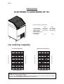
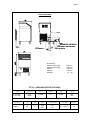
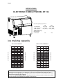
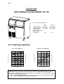
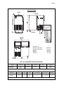
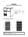
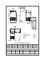
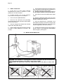
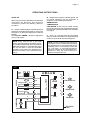
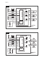
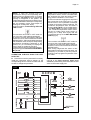
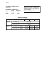
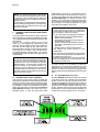
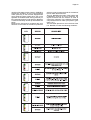
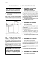
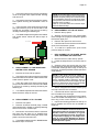
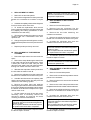
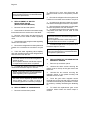
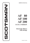
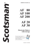
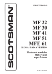
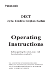
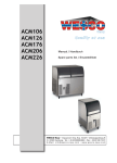
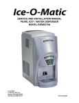
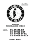
Page 1
Page 1
SERVICE MANUAL
NEW
EF SERIES
S
Electronic flakers
with storage
SCOTSMAN EUROPE - FRIMONT SPA
Via Puccini, 22 - 20010 Pogliano M.se - Milano - Italy
Tel. +39-02-93960.1 (Aut. Sel.)- Telefax +39-02-93550500
Direct Line to Service & Parts:
Phone +39-02-93960350 - Fax +39-02-93540449
ISO
900
1-C
Website: www.scotsman-ice.com
ert.
n. 0
080
E-Mail: [email protected]
REV. 04/2013
Page 2
Page 2
TABLE OF
CONTENTS
Table of contents
Specifications EF 103
Specifications EF 124
Specifications EF 156
Specifications EF 206
page
2
3
5
7
9
GENERAL INFORMATION AND INSTALLATION
Introduction
Unpacking and Inspection
Location and levelling
Electrical connections
Water supply and drain connections
Final check list
Installation practice
11
11
11
11
12
13
13
OPERATING INSTRUCTIONS
Start up
Operational checks
14
16
PRINCIPLE OF OPERATION (How it works)
Water circuit
Refrigerant circuit
Mechanical system
Operating pressures
Components description
20
20
22
23
24
ADJUSTMENT, REMOVAL AND REPLACEMENT PROCEDURES
Adjustment of the evaporator water level
Replacement of evaporator temperature sensor
Replacement of condenser temperature sensor
Replacement of ice level light control
Replacement of the gear motor rotation and speed sensor
Replacement of the reservoir water level sensor
Replacement of P.C. Board
Replacement of the ice spout
Replacement of the auger, water seal, bearings and coupling
Replacement of the gear motor assy
Replacement of fan motor
Replacement of drier
Replacement of the freezing cylinder
Replacement of air cooled condenser
Replacement of water cooled condenser
Replacement of water regulating valve (water cooled models)
Replacement of compressor
Replacement of the gear motor magnetic sensor
Wiring diagram
Service diagnosis
29
29
29
29
29
30
30
30
30
31
31
32
32
32
32
33
33
33
34
36
MAINTENANCE AND CLEANING INSTRUCTIONS
General
Icemaker
Cleaning instructions of water system
38
38
38
Page 3
Page 3
SPECIFICATIONS
ELECTRONIC FLAKER MODEL EF 103
Important operating requirements:
MIN
- Air temperature
10°C (50°F)
- Water temperature 5°C (40°F)
- Water pressure
1 bar (14 psi)
- Electr. voltage
variations fromvoltage
rating specified
on nameplate
-10%
MAX
40°C (100°F)
40°C (100°F)
5 bars (70 psi)
+10%
ice making capacity
AIR COOLED MODELS
10
Kg.
110
o°C
108
10
101
106
99
104
21
32
97
102
95
100
91
89
32
87
85
83
38
81
79
77
75
ICE PRODUCED PER 24 HRS.
93
AMBIENT TEMPERATURE
21
98
96
94
92
90
88
86
84
82
80
73
78
71
76
69
74
67
72
65
38
AMBIENT TEMPERATURE
103
ICE PRODUCED PER 24 HRS.
WATER COOLED MODELS
o°C
Kg.
105
70
32
27
21
15
WATER TEMPERATURE
10 o°C
32
27
21
15
10 o°C
WATER TEMPERATURE
NOTE. The daily ice-making capacity is directly related to the condenser air inlet temperature, water
temperature and age of the machine.
To keep your SCOTSMAN FLAKER at peak performance levels, periodic maintenance checks
must be carried out as indicated on page 36 of this manual.
Page 4
Page 4
SPECIFICATIONS
Dimensions:
HEIGHT (less legs)
HEIGHT (with legs)
WIDTH
DEPTH
WEIGHT
1006 mm.
1126 mm.
592 mm.
622 mm.
72 Kg.
EF103 - MACHINE SPECIFICATIONS
Model
Cond. unit
EF 103 AS
EF 103 WS
Basic electr.
230/50/1
Finish
Air
Water
S. Steel
Amps
Start
Amps
Watts
2.5
11
470
360
* A 15°C water temperature
Comp. HP
1/4
Electric power cons.
Kwh per 24 HR
10
8.5
Ice bin
cap
Water req.
lt/24 HR
30 Kg.
105**
440*
Nr. of wires
3 x 1.5 mm2
Amps fuse
10
Page 5
Page 5
SPECIFICATIONS
ELECTRONIC CUBELET MODEL EF 124
Important operating requirements:
MIN
- Air temperature
10°C (50°F)
- Water temperature
5°C (40°F)
- Water pressure
1 bar (14 psi)
- Electr. voltage
variations fromvoltage
rating specified
on nameplate
-10%
MAX
40°C (100°F)
35°C (90°F)
5 bars (70 psi)
+10%
ice making capacity
AIR COOLED MODELS
WATER COOLED MODELS
Kg.
o°C
120
10
o°C
Kg.
121
118
10
119
116
117
114
112
115
21
21
113
110
102
32
100
98
96
94
92
90
38
88
109
107
105
38
103
101
99
97
95
86
93
84
91
82
AMBIENT TEMPERATURE
104
ICE PRODUCED PER 24 HRS.
111
106
AMBIENT TEMPERATURE
ICE PRODUCED PER 24 HRS.
108
89
80
87
78
85
76
74
83
32
27
21
15
WATER TEMPERATURE
10 o°C
32
27
21
15
10 o°C
WATER TEMPERATURE
NOTE. With the unit in “built-in” conditions, the ice production is gradually reduced in respect to the
levels shown in the graph, up to a maximum of 10% at room temperatures higher than 32°C.
The daily ice-making capacity is directly related to the condenser air inlet temperature, water
temperature and age of the machine.
To keep your SCOTSMAN CUBELET at peak performance levels, periodic maintenance checks
must be carried out as indicated on page 36 of this manual.
Page 6
Page 6
SPECIFICATIONS
Dimensions:
HEIGHT (less legs)
HEIGHT (with legs)
WIDTH
DEPTH
WEIGHT
795 mm.
915 mm.
950 mm.
605 mm.
72 Kg.
EF 124 - MACHINE SPECIFICATIONS
Model
Cond. unit
EF 124 AS
EF 124 WS
Basic electr.
230/50/1
Finish
Air
Water
S. Steel
Amps
Start
Amps
Watts
3.8
17
600
500
* A 15°C water temperature
Comp. HP
3/8
Electric power cons.
Kwh per 24 HR
13.2
11.9
Ice bin
cap
Water req.
lt/24 HR
40 Kg.
130**
620*
Nr. of wires
3 x 1.5 mm2
Amps fuse
10
Page 7
Page 7
SPECIFICATIONS
ELECTRONIC FLAKER MODEL EF 156
Important operating requirements:
MIN
- Air temperature
10°C (50°F)
- Water temperature 5°C (40°F)
- Water pressure
1 bar (14 psi)
- Electr. voltage
variations fromvoltage
rating specified
on nameplate
-10%
MAX
40°C (100°F)
40°C (100°F)
5 bars (70 psi)
+10%
ice making capacity
AIR COOLED MODELS
WATER COOLED MODELS
o°C
Kg.
150
o°C
Kg.
160
10
21
10
146
156
21
152
32
38
130
32
126
122
118
114
38
110
148
144
140
136
132
AMBIENT TEMPERATURE
134
ICE PRODUCED PER 24 HRS.
138
AMBIENT TEMPERATURE
ICE PRODUCED PER 24 HRS.
142
106
128
102
98
124
32
27
21
15
WATER TEMPERATURE
10 o°C
32
27
21
15
10 o°C
WATER TEMPERATURE
NOTE. With the unit in “built-in” conditions, the ice production is gradually reduced in respect to the
levels shown in the graph, up to a maximum of 10% at room temperatures higher than 32°C.
The daily ice-making capacity is directly related to the condenser air inlet temperature, water
temperature and age of the machine.
To keep your SCOTSMAN FLAKER at peak performance levels, periodic maintenance checks
must be carried out as indicated on page 36 of this manual.
Page 8
Page 8
SPECIFICATIONS
Dimensions:
HEIGHT (less legs)
HEIGHT (with legs)
WIDTH
DEPTH
WEIGHT
1006 mm.
1126 mm.
950 mm.
605 mm.
88 Kg.
EF 156 - MACHINE SPECIFICATIONS
Model
Cond. unit
EF156 AS
EF156 WS
Basic electr.
230/50/1
Finish
Air
Water
S. Steel
Amps
Start
Amps
3.8
17
* A 15°C water temperature
Watts
650
Comp. HP
3/8
Electric power cons.
Kwh per 24 HR
14.7
Ice bin
cap
60 Kg.
Nr. of wires
3 x 1.5 mm2
Water req.
lt/24 HR
160**
1000*
Amps fuse
10
Page 9
Page 9
SPECIFICATIONS
ELECTRONIC FLAKER MODEL EF 206
Important operating requirements:
MIN
- Air temperature
10°C (50°F)
- Water temperature 5°C (40°F)
- Water pressure
1 bar (14 psi)
- Electr. voltage
variations fromvoltage
rating specified
on nameplate
-10%
MAX
40°C (100°F)
40°C (100°F)
5 bars (70 psi)
+10%
ice making capacity
AIR COOLED MODELS
WATER COOLED MODELS
o°C
202
10
196
21
192
200
10
198
21
196
188
194
184
192
190
172
32
168
164
160
156
38
152
148
144
ICE PRODUCED PER 24 HRS.
176
AMBIENT TEMPERATURE
180
ICE PRODUCED PER 24 HRS.
o°C
Kg.
32
188
186
184
38
182
180
178
176
174
172
170
168
AMBIENT TEMPERATURE
Kg.
200
166
140
164
136
162
160
132
158
128
156
124
154
32
27
21
15
WATER TEMPERATURE
10 o°C
32
27
21
15
10 o°C
WATER TEMPERATURE
NOTE. The daily ice-making capacity is directly related to the condenser air inlet temperature, water
temperature and age of the machine.
To keep your SCOTSMAN FLAKER at peak performance levels, periodic maintenance checks
must be carried out as indicated on page 36 of this manual.
Page 10
Page 10
SPECIFICATIONS
Dimensions:
HEIGHT (less legs)
HEIGHT (with legs)
WIDTH
DEPTH
WEIGHT
1006 mm.
1126 mm.
950 mm.
605 mm.
90 Kg.
EF206 - MACHINE SPECIFICATIONS
Model
Cond. unit
EF 206 AS
EF 206 WS
Basic electr.
230/50/1
Finish
Air
Water
S. Steel
Amps
Start
Amps
4
20
* A 15°C water temperature
Watts
760
Comp. HP
5/8
Electric power cons.
Kwh per 24 HR
17.4
Ice bin
cap
Water req.
lt/24 HR
60 Kg.
200**
1350*
Nr. of wires
3 x 1.5 mm2
Amps fuse
10
Page 11
Page 11
GENERAL INFORMATION AND INSTALLATION
A. INTRODUCTION
This manual provides the specifications and the
step-by-step procedures for the installation, startup and operation, maintenance and cleaning for
the SCOTSMAN EF series icemakers.
The Electronic Flakers are quality designed,
engineered and manufactured.
Their ice making systems are thoroughly tested
providing the utmost in flexibility to fit the needs
of a particular user.
NOTE. To retain the safety and performance
built into this icemaker, it is important that
installation and maintenance be conducted
in the manner outlined in this manual.
9. See data plate on the rear side of the unit
and check that local main voltage corresponds
with the voltage specified on it.
CAUTION. Incorrect voltage supplied to
the icemaker will void your parts
replacement program.
10. Remove the manufacturer’s registration card
from the inside of the User Manual and fill-in all
parts including: Model and Serial Number taken
from the data plate.
Forward the completed self-addressed
registration card to SCOTSMAN EUROPE
factory.
11. If necessary fit the four legs into their seats
on the machine base and adjust them to the
desired level.
B. UNPACKING AND INSPECTION
1. Call your authorized SCOTSMAN Distributor
or Dealer for proper installation.
2. Visually inspect the exterior of the packing
and skid. Any severe damage noted should be
reported to the delivering carrier and a concealed
damage claim form filled in subjet to inspection of
the contents with the carrier’s representative
present.
3. a) Cut and remove the plastic strip securing
the carton box to the skid.
b) Cut open the top of the carton and remove
the polystyre protection sheet.
c) Pull out the polystyre posts from the
corners and then remove the carton.
4. Remove the front and the rear panels of the
unit and inspect for any concealed damage.
Notify carrier of your claim for the concealed
damage as stated in step 2 above.
5. Remove all internal support packing and
masking tape. (Leg package and water inlet and
outlet hoses are located in the storage bin
compartment).
6. Check that refrigerant lines do not rub against
or touch other lines or surfaces, and that the fan
blades move freely.
C. LOCATION AND LEVELLING
WARNING. This Ice Flaker is designed for
indoor installation only. Extended periods
of operation at temperature exceeding
the following limitations will constitute
misuse under the terms of the SCOTSMAN
Manufacturer’s Limited Warranty
resulting in LOSS of warranty coverage.
1. Position the unit in the selected permanent
location.
Criteria for selection of location include:
a) Minimum room temperature 10°C (50°F)
and maximum room temperature 40°C (100°F).
b) Water inlet temperatures: minimum 5°C
(40°F) and maximum 35°C (90°F).
c) Well ventilated location for air cooled models
(Clean the air cooled condenser at frequent
intervals).
d) Service access: adequate space must be
left for all service connections through the rear of
the ice maker. A minimum clearance of 15 cm
(6") must be left at the sides of the unit for routing
cooling air drawn into and exhausted out of the
compartment to maintain proper condensing
operation of air cooled models.
2. Level the unit in both the left to right and front
to rear directions.
7. Check that the compressor fits snugly onto
all its mounting pads.
D. ELECTRICAL CONNECTIONS
8. Use clean damp cloth to wipe the surfaces
inside the storage bin and the outside of the
cabinet.
See data plate for current requirements to
determine wire size to be used for electrical
connections. All SCOTSMAN icemakers require
a solid earth wire.
Page 12
Page 12
All SCOTSMAN ice machines are supplied from
the factory completely pre-wired and require only
electrical power connections to the wire cord
provided at the rear of the unit.
Make sure that the ice machine is connected to
its own circuit and individually fused (see data
plate for fuse size).
The maximum allowable voltage variation should
not exceed -10% and +10% of the data plate
rating. Low voltage can cause faulty functioning
and may be responsible for serious damage to
the overload switch and motor windings.
NOTE. All external wiring should conform to
national, state and local standards and
regulations.
Check voltage on the line and the ice maker’s
data plate before connecting the unit.
Connect the 3/4" GAS male fitting of the water
inlet, using the flexible hose supplied to the cold
water supply line with regular plumbing fitting
and a shut-off valve installed in an accessible
position between the water supply line and the
unit.
WATER DRAIN
The recommended drain tube is a plastic or
flexible hose with 18 mm (3/4") I.D. which runs to
an open trapped and vented drain. When the
drain is a long run, allow 3 cm pitch per meter
(1/4" pitch per foot).
Install a vertical open vent on drain line high point
at the unit drain connection to ensure good
draining.
The ideal drain receptacle is a trapped and
vented floor drain.
WATER DRAIN - WATER COOLED MODELS
E.
WATER SUPPLY AND DRAIN
CONNECTIONS
GENERAL
When choosing the water supply for the ice flaker
consideration should be given to:
a) Length of run
b) Water clarity and purity
c) Adequate water supply pressure
Since water is the most important single ingredient
in producting ice you cannot emphasize too
much the three items listed above.
Low water pressure, below 1 bar may cause
malfunction of the ice maker unit.
Water containing excessive minerals will tend to
produce scale build-up on the interior parts of the
water system while too soft water (with too lo
contents of mineral salts), will produce a very
hard flaker ice.
Connect the 3/4" GAS male fitting of the
condenser water drain, utilizing a second flexible
hose to the open trapped and vented drain.
This additional drain line must not interconnect to
any other of the units drains.
NOTE. The water supply and the water drain
must be installed to conform with the local
code. In some case a licensed plumber and/
or a plumbing permit is required.
The water can be pumped out up to 1.5 m rise
or
HAND DISCONNECT
SWITCH
WATER
VALVE
WATER
FILTER
POWER
WATER SUPPLY
Connect the 3/4" GAS male of the water inlet
fitting, using the flexible hose supplied to the cold
water supply line with regular plumbing fitting
and a shut-off valve installed in an accessible
position between the water supply line and the
unit.
If water contains a high level of impurities, it is
advisable to consider the installation of an
appropriate water filter or conditioner.
WATER SUPPLY - WATER COOLED MODELS
WATER INLET
WATER DRAIN
to 30 m on horizontal length.
HAND DISCONNECT
SWITCH
WATER
VALVE
WATER
FILTER
POWER
WATER INLET
The water cooled versions of SCOTSMAN Ice
Makers require two separate inlet water supplies,
one for the water making the flaker ice and the
other for the water cooled condenser.
WATER DRAIN
Page 13
Page 13
1. Is the unit in a room where ambient
temperatures are within a minimum of 10°C
(50°F) even in winter months?
7. Have the bolts holding the compressor down
been checked to ensure that the compressor is
snugly fitted onto the mounting pads?
8. Check all refrigerant lines and conduit lines
to guard against vibrations and possible failure.
2. Is there at least a 15 cm (6") clearance
around the unit for proper air circulation?
9. Have the bin liner and cabinet been wiped
clean?
3.
10. Has the owner/user been given the User
Manual and been instructed on the importance of
periodic maintenance checks?
F.
FINAL CHECK LIST
Is the unit level? (IMPORTANT)
4. Have all the electrical and plumbing
connections been made, and is the water supply
shut-off valve open?
5. Has the voltage been tested and checked
against the data plate rating?
11. Has the Manufacturer’s registration card
been filled in properly? Check for correct model
and serial number against the serial plate and
mail the registration card to the factory.
6. Has the water supply pressure been checked
to ensure a water pressure of at least 1 bar
(14 psi).
12. Has the owner been given the name and the
phone number of the authorized SCOTSMAN
Service Agency serving him?
G. INSTALLATION PRACTICE
WARNING. This icemaker is not designed for outdoor installation and will not function in
ambient temperatures below 10°C (50°F) or above 40°C (100°F).
This icemaker will malfunction with water temperatures below 5°C (40°F) or above 35°C
(90°F).
Page 14
Page 14
OPERATING INSTRUCTIONS
START UP
B. Elapsed the 3 minutes - stand by period - the
unit starts operating with the activation in
sequence of the following assemblies:
GEAR MOTOR
COMPRESSOR
FAN MOTOR (if unit is an air cooled version)
kept under control by the condenser temperature sensor which has its probe within the condenser
fins (Fig.2).
After having correctly installed the ice maker and
completed the plumbing and electrical
connections, perform the following “Start-up”
procedure.
A. Open the water supply line shutoff valve and
put the unit under electrical power by moving the
main switch, on the power supply line, to the ON
position.
The first LED - GREEN - will glow to signal that
unit is under power.
C. After 2 or 3 minutes from the compressor
start up, observe that flaker ice begins dropping
off the ice spout to fall into the storage bin.
NOTE. Every time the unit is put under
power, after being kept for sometime in shutoff conditions (electrically disconnected) the
RED LED will blink for 3 minutes after which
the unit will start up with the immediate
operation of the gear motor assembly and,
after few seconds, of the compressor assy
(Fig.1).
NOTE. The first ice bits that drop into the ice
storage bin are not so hard as the evaporating
temperature has not yet reached the correct
operating value. It is necessary to allow the
ice - just made - to cure itself and wait for
about ten minutes for the evaporating temperature to reach the correct value so to
make more hard bits of ice.
FIG. 1
WATER
LEVEL
RESET
88
GEAR MOTOR
ROTATION
12
12
CONDENSER TEMP.
T>1°C
11
EVAPORATOR TEMP.
10
77
DATA PROCESSOR
SENSORS
13
13
RELAYS
55
44
ICE LEVEL CONTROL
LL
1
N
N
2
2
GEAR MOTOR
33
9
COMPRESSOR
CONTACTOR COIL
66
TRIAC
FAN MOTOR
TRANSF.
ELECTRONIC
CARD
Page 15
Page 15
FIG. 2
WATER
LEVEL
RESET
88
ROTATION
12
12
CONDENSER TEMP. T 40÷50°C
11
EVAPORATOR TEMP.
10
10
77
DATA PROCESSOR
SENSORS
13
GEAR MOTOR
RELAYS
55
44
ICE LEVEL CONTROL
L
1
N
2
GEAR MOTOR
33
9
COMPRESSOR
CONTACTOR COIL
66
TRIAC
FAN MOTOR
TRANSF.
ELECTRONIC
CARD
FIG. 3
WATER
LEVEL
RESET
88
GEAR MOTOR
ROTATION
12
12
CONDENSER TEMP.
T>75°C
11
EVAPORATOR TEMP.
10
10
77
DATA PROCESSOR
SENSORS
13
13
RELAYS
55
44
ICE LEVEL CONTROL
COMPRESSOR
N
1
2
GEAR MOTOR
33
9
L
CONTACTOR COIL
66
TRIAC
FAN MOTOR
TRANSF.
ELECTRONIC
CARD
Page 16
Page 16
NOTE. If, after ten minutes from the
compressor start-up, the evaporating temperature has not dropped down to a value
lower than -1°C (30°F) due to an insufficient
quantity of refrigerant in the system, the
evaporating temperature sensor detects such
an abnormal situation and stops consequently
the unit operation (drive motor keeps on
working for 3' delay then stops).
In this circustance, the 5th warning YELLOW
LED will blink.
NOTE. On air cooled models, the condenser
temperature sensor, which is located within
the condenser fins, keep the head (condensing) pressure between 17 and 18 bar.
In case of condenser clogging such to prevent
the proper flow of the cooling air or, in case
the fan motor is out of operation or shortage
of water in the water cooled condenser, the
condenser temperature rises and when it
reaches 70°C (160°F) - for air cooled version
- and 60°C (140°F) - for water cooled version
- the condenser temperature sensor shutsoff the ice maker (drive motor keeps on
working for 3' delay then stops) with the
consequent light-up of the RED WARNING
LIGHT (Fig.3).
The machine will remain in OFF mode for
one hour then it will restart automatically.
In case the unit trips OFF again in alarm for
3 times in 3 hours, the machine SHUTS OFF
DEFINITIVELY. After having diagnosed and
eliminated the cause of the poor evaporating
temperature (insufficient refrigerant in the
system, etc.) it is necessary to unplug and
plug in again to restart the machine.
The unit, before resuming the total operation,
will go through the usual 3 minutes STANDBY period.
The machine will remain in OFF mode for
one hour then it will restart automatically.
In case the unit trips OFF again in alarm for
3 times in 3 hours, the machine SHUTS OFF
DEFINITIVELY.
After having diagnosed the reason of the
temperature rise and removed its cause, it is
necessary to proceed as per the previous
“NOTE” to start up again the operation of the
ice maker.
OPERATION CHECKS UPON THE UNIT
START UP
D. Remove front service panel and if necessary
install the refrigerant service gauges on the
corresponding Service valves to check both the
HI and LO refrigerant pressures.
E. Check for the correct CUT-OUT and
CUT-IN of the float reservoir water level
sensors by first shutting closed the water shutoff
valve on the water supply line.
FIG. 4
WATER
LEVEL
RESET
88
GEAR MOTOR
ROTATION
12
12
CONDENSER TEMP.
11
EVAPORATOR TEMP.
10
10
77
DATA PROCESSOR
SENSORS
13
13
RELAYS
55
44
ICE LEVEL CONTROL
L
L
1
N
2
GEAR MOTOR
33
9
COMPRESSOR
CONTACTOR COIL
66
TRIAC
FAN MOTOR
TRANSF.
ELECTRONIC
CARD
Page 17
Page 17
This will cause a gradual decrease of the water
level in the float reservoir and as soon as the level
gets below the sensors, the flaker stops to operate (drive motor keeps on working by 3' delay
then stops) and the YELLOW warning LED will
glow to signal the shortage of water (Fig. 4).
F. Check for correct operation of the ice level
control, by putting some ice so to cut the light
beam of the sensing eyes.
This interruption will cause an immediate blinking
of the Bin Full YELLOW LED located on the front
of the P.C. Board and after about 10 seconds
causes the shutoff of the unit (compressor first
and 3' later the gear reducer) with the simultaneous lighting (steady) of the Same LED
signalling the full bin situation (Fig. 5).
NOTE. The water level sensor detects the
presence of sufficient water in the float
reservoir and confirms it to the micro
processor by maintaining a low voltage
current flow between the two sensors using
the water as conductor.
Remove the ice bin so to allow the resumption of
the light beam previously interrupted. After about
10 seconds the flaker will resume - through the 3
minutes STAND-BY period - the ice making
process with the extinguishing of the YELLOW
LED.
WARNING. The use of de-mineralized
water (water with no salt content) having
an electrical conductivity lower than 30
µS, will cause the ability of the water
sensors to vanish with the consequent
CUT-OUT of the flaker operations and the
glowing of the YELLOW LED of shortage
of water, even though that water is indeed
in the reservoir.
NOTE. The ICE LEVEL CONTROL
(INFRA-RED SYSTEM) is independent of
the temperature however, the reliability of
its detection can be affected by external
light radiations or by any sort of dirt and
scale sediment which may deposit
directly on the light source and on the
receiver.
To prevent any possible ice maker
malfunction, due to negative affection of
the light detector, it is advisable to locate
the unit where it is not reached by any
direct light beam or light radiation, also
it is recommended to keep the bin door
constantly closed.
After this, open the water supply line shutoff
valve to fill up again the float reservoir, the
YELLOW LED goes off while the RED LED
starts blinking.
After 3 minutes the unit resumes its total operation
with the immediate start-up of the gear motor
and, 2 seconds later, of the compressor.
FIG. 5
WATER
LEVEL
RESET
88
GEAR MOTOR
ROTATION
12
12
CONDENSER TEMP.
11
EVAPORATOR TEMP.
10
10
77
DATA PROCESSOR
SENSORS
13
13
RELAYS
55
44
ICE LEVEL CONTROL
L
L
1
N
2
GEAR MOTOR
33
9
COMPRESSOR
CONTACTOR COIL
66
TRIAC
FAN MOTOR
TRANSF.
ELECTRONIC
CARD
Page 18
Page 18
NOTE. During the life of the machine the Ice
Level Control may require a recalibration
mainly when the glass of the two optical eyes
are covered by a thin lay of scale.
To do it just follow the following procedure:
• With unit OFF push and old the Reset
Button of the PC Board
• Give power to the machine through the
Green Master Switch
• Hold the PC Board Reset Button till the
leds start to blink/flash (more or less 10
seconds)
• Release the PC Board Reset Button
The Optical Ice Level Control is now
recalibrated.
Check for the correct operation of the Optical
Ice Level Control by plasing a handfull of ice
in between the two eyes.
The Bin Full yellow led must start to blink/
flash immediately and, 10 seconds later, the
machine must trip OFF.
G. If previously installed, remove the refrigerant
service gauges and re-fit the unit service panels
previously removed.
H. Instruct the owner/user on the general
operation of the ice machine and about the
cleaning and care it requires.
As soon as the water into the Sealed Water
Reservoir reaches the maximum level, the two
metal pins close the electrical contact through
the water, transmitting a low voltage current to
the PC Board.
The PC Board activates the Water Drain
Pump for 15 seconds pumping out most of
the water contained into the Sealed Water
Reservoir.
The water can be pumped out up to 1.5 m rise
or
PWD SYSTEM
HAND DISCONNECT
SWITCH
WATER
VALVE
COMPONENTS
WATER
FILTER
The components of the Pump Out Water Drain
System are
•
•
•
•
Sealed water tank
PC Board & Sensor
Sealed Water Pump
Check Valve
OPERATION
POWER
WATER INLET
WATER DRAIN
to 30 m on horizontal length.
All water coming from the overflow, and from the
melted ice is collected inside the Sealed Water
Reservoir.
HAND DISCONNECT
SWITCH
WATER
VALVE
WATER
FILTER
POWER
WATER INLET
WATER DRAIN
A Check Valve, located on the water drain hose,
Page 19
Page 19
prevents the coming back of the discharged
water.
SCHEMATIC SYSTEM
Drain fitting
Storage bin
Overflow drain
tube
Vented tube
Water
level
sensors
Check
valve
Drain out
Sealed
water
tank
Water
pump
Storage bin
drain tube
Water tank
inlet fitting
Page 20
Page 20
PRINCIPLE OF OPERATION
WATER CIRCUIT
The water enter in the machine through the water
inlet fitting which incorporates a strainer and it is
located at the rear side of the cabinet and then it
goes to the water reservoir flowing through a float
valve.
NOTE. The presence of the water in the float
reservoir is detected by a system of two
sensors which operates in conjunction with
the P.C. Board. The two sensors use the
water as a conductor to maintain a low voltage
current flow between them signalling in this
way to the P.C. Board the presence of the
water in the reservoir. In case the water used
is very soft (de-mineralized) or the float
reservoir gets empty the current flow between
the sensors become so weak or is no longer
maintained that, as consequence, the P.C.
Board shutoff the flaker operation (drive motor
keeps on working by 3' delay then stops) with
the simultaneous glowing of the YELLOW
LED signalling “Shortage of water”.
The float reservoir is positioned at the side of the
freezing cylinder at such an height to be able to
maintain a constant water level around the freezer
auger.
In fact, the water flows from the reservoir into the
bottom inlet of the freezing cylinder to sorround
the stainless steel auger which is vertically fitted
in the center of the freezer.
In the freezer the incoming water gets chilled into
soft (slush) ice which is moved upward by the
rotating action of the auger. The stainless steel
auger that rotates counter-clockwise within the
freezer, is powered by a direct drive gear motor
and carries the ice upward along the refrigerated
freezer inner walls and by doing so the ice gets
progressively thicker and harder.
ICE SPOUT
FLOAT TANK
FLOAT VALVE
WATER INLET LINE
FREEZER
FREEZER WATER
FEED LINE
The ice, being costantly lifted up, meet the toothed
point of the ice breaker which is fitted on the top
end of the auger, where it gets compacted,
cracked and forced to change from vertical into
horizontal motion to be discharged out, through
the ice spout, into the storage bin.
By running the ice maker, i.e. by putting the unit
under power, starts the automatic and continuous
icemaking process which would not stop until the
ice storage bin gets filled-up to the level of the
control “eyes” located on the sides of the ice spout.
As the ice level raises to interrupt the light beam
running between the two infrared Leds, the unit
stops after six seconds (compressor first and 3'
later the gear reducer), with the simulteneous
glowing of the YELLOW LED signalling the “Full
Bin” situation.
NOTE. The interruption of the light beam
between the two light sensors is immediately
signalled by the blinking of the BIN FULL
YELLOW LED located on the front of the
P.C. Board.
After about 10" of steady interruption of
the light beam the unit stops (drive motor
keeps on working by 3' delay then stops) and
the “Full Bin” YELLOW LED glows steady.
The ten seconds of delay prevent the unit
from stopping for any undue reason like the
momentarily interruption of the light beam
caused by the flakes that slides along the ice
spout before dropping into the bin.
As some ice gets scooped out from the storage
bin, the light beam between the two sensors
resumes (fast blinking of YELLOW LED) and ten
seconds later the ice machine restarts the ice
making process - going always through the 3'
stand by - and the YELLOW LED goes off.
REFRIGERANT CIRCUIT
The hot gas refrigerant discharged out from the
compressor reaches the condenser where, being
cooled down, condenses into liquid.
Flowing into the liquid line it passes through the
drier filter, then it goes all the way through the
capillary tube where it looses some of its pressure
so that its pressure and temperature are lowered.
Next, the refrigerant enters into the evaporator
coil wrapped around the freezer inner tube.
The water being constantly fed at the interior of
the freezer inner tube, exchange heat with the
refrigerant circulating into the evaporator coil,
this cause the refrigerant to boil-off and evaporate, thereby it changes from liquid into vapor.
The vapor refrigerant then passes through the
suction accumulator and through the suction line
where the refrigerant exchanges heat with the
one flowing into the capillary tube (warmer) before
being sucked into the compressor to be recirculated.
The refrigerant heat pressure is kept between
two pre-set values 17÷18 bar - 245÷260 psig by
the condenser temperature sensor which has its
probe located within the condenser fins - in air
cooled versions.
This condenser temperature sensor, when
senses a rising of the condenser temperature
beyond the pre-fixed limit, changes its electrical
resistance and send a low voltage power flow to
Page 21
Page 21
the MICRO-PROCESSOR of the P.C. Board
which energizes, through a TRIAC, the Fan
Motor in ON-OFF mode.
When the opposite situation occures, i.e. the
condenser temperature gets below the pre-fixed
NOTE. In case the condenser temperature probe
senses that the condenser temperature has
rised to 70°C (160°F) - on air cooled versions
- or 60°C (140°F) - on water cooled versions for one of the following abnormal reasons:
CLOGGED CONDENSER (Air cooled version)
INSUFFICIENT FLOW OF COOLING
WATER (Water cooled version)
FAN MOTOR OUT OF OPERATION (Air
cooled version)
AMBIENT TEMPERATURE HIGHER THEN
43°C (110°F)
it causes the total and immediate SHUT-OFF
of the machine (drive motor keeps on working
by 3' delay then stops) in order to prevent the
unit from operating in abnormal and dangerous
conditions. When the ice maker stops on
account of this protective device, there is a
simultaneous glowing of the RED LED, warning
the user of the Hi Temperature situation. The
machine will remain in OFF mode for one hour
then it will restart automatically. In case the unit
trips OFF again in alarm for 3 times in 3 hours,
the machine SHUTS OFF DEFINITIVELY.
After having eliminated the source of the
excessive con-denser temperature, to restart
the ice machine it is necessary to unplug and
plug in again. The RED LED starts blinking
and three minutes later the flaker unit resume
its normal operating mode. The condenser
temperature sensor has a further safety
function which consist in preventing the unit
from operating in Lo-ambient conditions i.e.
when the condenser body temperature equivalent to the ambient temperature - is
lower then 1°C 34°F (Fig.6). As soon as the
ambient temperature rises up to 5°C (40°F)
the PC Board will automatically restarts the
machine through the three minutes delay time.
EVAPORATOR
CAPILLARY TUBE
DISCHARGE LINE
COMPRESSOR
CONDENSER
SUCTION LINE
ACCUMULATOR
FAN MOTOR
limit, the temperature sensor changes again its
electrical resistance reducing therefore the current
flow to the P.C. Board to cause a temporary stop
of the Fan Motor.
On the water cooled versions, the refrigerant
head pressure is kept at the constant value of
17 bar (245 psig) by the metered amount of
water passing through the condenser which is
regulated by the action of the Water Regulating
Valve that has its capillary tube connected to the
liquid refrigerant line. As pressure increases, the
water regulating valve opens to increase the flow
of cooling water to the condenser.
FIG. 6
WATER
LEVEL
RESET
88
GEAR MOTOR
ROTATION
12
12
CONDENSER TEMP.
T<1°C
11
EVAPORATOR TEMP.
10
10
77
DATA PROCESSOR
SENSORS
13
13
RELAYS
55
44
ICE LEVEL CONTROL
L
1
N
2
2
GEAR MOTOR
33
9
COMPRESSOR
CONTACTOR COIL
66
TRIAC
FAN MOTOR
TRANSF.
ELECTRONIC
CARD
Page 22
Page 22
directly fitted in the gear case through which it
drives - in counter clockwise rotation at a speed
of 9.5 r.p.m. - the freezer auger being linked to it
by the ratched coupling.
The refrigerant suction or Lo-pressure sets - in
normal ambient conditions (21 °C) - on the value
of 2.4 - 2.6 bar (35 - 38 psig) after few minutes
from the unit start-up.
This value can vary of 0.1 or 0.2 bar (1.5÷3 psig)
in relation to the water temperture variations
influencing the freezer cylinder.
NOTE. In the event the gear motor will tend
to rotate in the wrong direction (counterclockwise) or not rotating at all or rotating at
lower speed the unit will stop immediately
with the glowing of the WARNING YELLOW
LED on account of the intervention of the
Electromagnetic Safety Device - based on
Hall Effect principle.
NOTE. If, after ten minutes from the unit start
up, no ice is made and the evaporating
temperature detected by the evaporator
sensor results to be higher than -1°C (30°F)
the ice maker stops (compressor first and 3'
later the gear reducer) and the 5TH
WARNING YELLOW LED blinks.
The machine will remain in OFF mode for
one hour then it will restart automatically.
In case the unit trips OFF again in alarm for
3 times in 3 hours, the machine SHUTS OFF
DEFINITIVELY.
The machine will remain in OFF mode for
one hour then it will restart automatically.
In case the unit trips OFF again in alarm for
3 times in 3 hours, the machine SHUTS OFF
DEFINITIVELY.
After having diagnosed and eliminated the
source of the failure, to restart the unit it is
necessary to switch OFF and ON the power
line main disconnnect switch (Fig. 7).
The RED LED will start blinking and after
3 minutes the ice maker will resume its total
operations by running first the gear motor
and then the compressor.
MECHANICAL SYSTEM
The mechanical system of the SCOTSMAN
Flaker machines consists basically of a gear
motor assembly which drives, through a ratched
coupling, a worn shaft or auger placed on its
vertical axis within the freezing cylinder.
The gear motor is made of a single phase electric
motor with a permanent capacitor. This motor is
FIG. 7
WATER
LEVEL
RESET
88
GEAR MOTOR
ROTATION
12
12
CONDENSER TEMP.
11
EVAPORATOR TEMP.
10
10
77
DATA PROCESSOR
SENSORS
13
13
RELAYS
44
COMPRESSOR
1
2
GEAR MOTOR
33
9
N
66
55
ICE LEVEL CONTROL
L
L
CONTACTOR COIL
TRIAC
FAN MOTOR
TRANSF.
ELECTRONIC
CARD
Page 23
Page 23
REFRIGERANT METERING DEVICE:
capillary tube
REFRIGERANT CHARGE (R 404 A)
air cooled
water cooled
EF 103
450 gr
300 gr
EF 124
420 gr
300 gr
EF 156
490 gr
300 gr
EF 206
660 gr
520 gr
NOTE. Before charging the refrigerant system
always check the type of refrigerant and
quantity as specified on the individual ice
machine dataplate.
The refrigerant charges indicated are relatives
to averages operating conditions.
OPERATING PRESSURES
(With 21°C ambient temperature)
EF 103
Discharge
pressure
Suction
pressure
EF 124
EF 156
Air cooled
17 - 18 bar
245 - 260 psig
Water cooled
17 bar
245 psig
EF 206
Air cooled
2.6 bar
38 psig
2.2 bar
32 psig
2.6 bar
38 psig
2.5 bar
36 psig
Water cooled
2.7 bar
39 psig
2.5 bar
36 psig
2.6 bar
38 psig
2.4 bar
35 psig
Page 24
Page 24
COMPONENTS DESCRIPTION
A. GREEN MASTER SWITCH PUSH
BUTTON
Located in the front of the machine it’s used to
switch ON and OFF the unit by pushing its green
push button. When ON, its green light is ON as
well.
NOTE. The machine will remain in OFF
mode for one hour then it will restart
automatically.
In case the unit trips OFF again in alarm for
3 times in 3 hours, the machine SHUTS OFF
DEFINITIVELY.
To restart the unit after the shutoff caused by
the hi evaporating temperature, it is necessary to switch OFF and ON the power line
main disconnect Switch.
B. RED ALARM/RE-SET PUSH BUTTON
Located in the front of the machine (just beside
the Master Switch) it works in conjuction with the
PC Board and it’s activated when:
• Consensing temperature is higher then 70°C
(air cooled version) - ON steady with machine
in OFF mode
• Consensing temperature is higher then 60°C
(water cooled version) - ON steady with
machine in OFF mode
• Condenser sensor out of order - Blinking
twice and repeat with machine in OFF mode
• Condenser air filter need to be cleaned - ON
steady with machine in ON mode
• Water system need to be cleaned - Slow
blinking with machine in ON mode.
• Pump discharge system out of order - Blinking
fast with machine in OFF mode
On the first two cases it’s possible to Re-Set the
operation of the machine pushing and hold the
Red Alarm Re-Set Button by 5" till the Red Light
is OFF.
On the third case, it’s necessary first to replace
the condenser sensor then, push and hold for 5"
the Red Re-Set Button.
On the last case (Pump discharge system) to
Re-Set switch OFF and ON the machine.
C. EVAPORATOR TEMPERATURE
SENSOR
The evaporator sensor probe is inserted into its
tube well, which is welded on the evaporator
outlet line, it detects the temperature of the
refrigerant on the way out from the evaporator
and signals it by suppying a low voltage current
flow to the P.C. Board Micro-Processor.
According to the current received, the microprocessor let the ice maker to continue its
operations. In case the evaporating temperature, after 10 minutes from the unit start-up, does
not go below -1°C (30°F) due to shortage of
refrigerant in the system the evaporator sensor
signal reaching the microprocessor is such to
stop immediately the unit operation (drive motor
keeps on working by 3' delay then stops), with the
5th Warning YELLOW LED that blinks.
D. WATER LEVEL SENSOR
This sensor system consist of two small stainless
steel rods vertically fitted on the inner face of the
reservoir cover and electrically connected to the
low voltage circuit of the P.C. Board.
When the cover of the reservoir is positioned in
its place the tips of both the rods dip into the
reservoir water and detects and signals its
presence by making use of its electrical
resistance.
NOTE. In the event of shortage of water in
the reservoir or, in case the water used is too
soft (de-mineralized) to cause greater
resistence to the current flow (conductivity
lower than 30 µS) this sensor system causes
the shutoff of the machine (drive motor
keeps on working by 3' delay then stops), to
protect it from running with an interrupted or
inadequate water supply. In this situation the
YELLOW LED will glow to warn of the
machine shutoff and the reason why.
E.
CONDENSER TEMPERATURE SENSOR
The condenser temperature sensor probe,
located within the condenser fins (air cooled
version) or in contact with the tube coil (water
cooled version) detects the condenser temperature variations and signals them by supplying
current, at low voltage, to the P.C. BOARD.
In case the condenser temperature sensor
detects a temperature at the condenser lower
than +1°C (33°F) that signify that the ambient
temperature is at the same value, therefore it is
too low for the correct unit operation, the sensor
signals to the microprocessor to stop immediately
or to do not start the unit operations up to the
moment that the ambient temperature will rise to
more acceptables conditions (5°C).
In the air cooled versions, in relation to the
different current received, the micro processor of
the P.C. BOARD supplies, through a TRIAC, the
power at high voltage to the fan motor so that it
can cool the condenser and reduce its temperature.
In the event the condenser temperature rises
and reaches 70°C or 60°C the current arriving to
the micro processor is such to cause an immediate and total stop of the machine operation
(drive motor keeps on working by 3' delay then
stops).
Page 25
Page 25
NOTE. The machine will remain in OFF mode
for one hour then it will restart automa-tically.
In case the unit trips OFF again in alarm for
3 times in 3 hours, the machine SHUTS OFF
DEFINITIVELY.
To restart the unit after the shutoff caused by
the hi condenser temperature, it is necessary
to switch OFF and ON the power line main
disconnect Switch.
F.
GEAR MOTOR ROTATION AND SPEED
SENSOR
This safety device is housed on top of the Drive
Motor and detects - based on Hall Effect principle
- the rotating speed and rotating direction of the
drive Motor.
Should the rotating speed drop below
1300 r.p.m. the magnitude measured by this
device is such to signal to the microprocessor to
stop the unit and light-up the YELLOW LED.
About the same reaction occures when the drive
motor will tend to rotate in the wrong direction
(counterclockwise) situation that, if it occures,
will greatly affect all the freezer and gear reducer
components.
NOTE. The machine will remain in OFF mode
for one hour then it will restart automa-tically.
In case the unit trips OFF again in alarm for
3 times in 3 hours, the machine SHUTS OFF
DEFINITIVELY. To restart the unit after the
shutoff caused by this safety device, it is
necessary first to eliminate the cause that
has generated the intervention of the device
and then switch OFF and ON the power line
main disconnect switch.
interrupted for as long as 10 seconds, the ice
machine stops (drive motor keeps on working by
3' delay then stops) with the glowing-up of the
2nd YELLOW LED to monitor the full ice bin
situation. The 10 seconds of delay prevents that
any minimum interruption of the light beam due
to the regular ice chuting through the ice spout
may stop the operation of the unit.
NOTE. During the life of the machine the Ice
Level Control may require a recalibration
mainly when the glass of the two optical eyes
are covered by a thin lay of scale.
To do it just follow the following procedure:
• With unit OFF push and old the Reset
Button of the PC Board
• Give power to the machine through the
Green Master Switch
• Hold the PC Board Reset Button till the
leds start to blink/flash (more or less 10
seconds)
• Release the PC Board Reset Button
The Optical Ice Level Control is now
recalibrated.
Check for the correct operation of the Optical
Ice Level Control by plasing a handfull of ice
in between the two eyes.
The Bin Full yellow led must start to blink/
flash immediately and, 10 seconds later, the
machine must trip OFF.
As soon as the ice is scooped out (with the
resumption of the light beam between the two
infrared sensor of ice level control) 10 seconds
later the ice machine resumes its operation with
the simul-taneous extinguishing the 2nd YELLOW
LED.
H. P.C. BOARD (Data processor)
G. ICE BIN LEVEL LIGHT CONTROL
The electronic ice bin level control, located into
the ice spout, has the function to stop the operation
of the ice machine when the light beam between
the light source and the sensor gets interrupted
by the flake ice which accumulates in the spout.
When the light beam is interrupted the Bin Full
YELLOW LED located in the front of the P.C.
BOARD blinks; in case the light beam gets
The P.C. BOARD, fitted in its plastic box located
in the front of the unit, consists of two separated
printed circuits one at high and the other at low
voltage and protected by fuses. Also it consists of
five aligned LEDS monitoring the operation of the
machine of six jumpers (TEST used only in the
factory, 60/70°C used to set up the PC Board at
proper safety cut out condensing temperature, 6/
12 M to set up the PC Board to 6 or 12 months
Page 26
remind opf the water system cleaning, PURGE to
activate the operation of the Purge Solòenoid
Valve (used only on the machine equipped with
purge Solenoid Valve), PWD ON to set up the
operation of the Water Drain Pump (used only on
EFC series) and 3'/60? To set up the PC Board for
3 or 60 minutes delay at start up as detailed here
below.
Moreover the PC Board is equipped with input
terminals for the leads of the sensor probes as
Page 26
well as input and output terminals for the leads of
the ice maker electrical wires.
The P.C. BOARD is the brain of the system and
it elaborates, through its micro processor, the
signals received from the sensors in order to
control the operation of the different electrical
components of the ice maker (compressor, gear
motor, etc.).
The five LEDS, placed in a row in the front of the
P.C. BOARD, monitor the following situations:
Page 27
Page 27
TO BY-PASS THE 3'/60' STAND BY TIME, SYMPLY JUMP "TEST" CONTACTS WITH PCB ENERGIZED
I.
JUMPERS
The Flaker PC Board is equipped by three jumpers:
J1
PURGE Used on machine equipped with Water
Purge Valve to purge out the water
from the water system every 12 hours
and when the machine restart from the
Bin Full
JUMP IN - Purge activated
JUMP OUT - Purge disactivated
PWD
Used to Pump Out the water by means
of the Progressive Water Pump
supplied as a kit
JUMP IN - No Progressive Water Pump
installed/in operation
JUMP OUT - Progressive Water Pump
installed/in operation
3’/60’
Delay time at start up
JUMP IN - 3 minutes delay
JUMP OUT - 60 minutes delay
J2
TEST
6/12 M
Factory use ONLY
Cleaning remind for the water system Red Light blinks/flashes with machine
ON
JUMP IN - 12 months set up
JUMP OUT - 6 months set up
60/70°C Set up of the Safety Condensing
Temperature Sensor
JUMP IN - 70°C
JUMP OUT - 60°C
J.
EXTERNAL SWITCHES SOCKET
Connected to the external Green Master and
Red Alarm Reset Switches, it receives power
from the Master Switch as well as it provides
power to the Red Alarm switch in order to signal
any possible uncorrect operation condition of the
machine as clogged air filter (air cooled version
only) or short/missing of condensing water (water
cooled version) as detailed at item B.
It signal also the time for the cleaning of the water
system of the machine, cleaning that can be
change, according to the local water conditions,
from six month (standard - Jump In) to twelve
months (Jump Out).
Once cleaned the water system, it’s necessary to
cancel the time stored into the PC Board by
pushing and hold for more then 5" the Red Alarm
Re-Set Button till it stops to blink.
K.
FLOAT RESERVOIR
The float reservoir consists of a plastic water pan
on which is fitted a float valve with its setting
screw. The float valve modulate the incoming
water flow to maintain a constant water level in
the reservoir, level that corresponds to the one in
the freezing cylinder to ensure proper ice formation
and fluidity.
On the inner side of the reservoir cover are fitted
the two water level sensors which detects the
presence or the shortage of water in the reservoir.
NOTE. It is very important to make sure of the
correct fitting of the cover on the reservoir in
order to enable the sensor to efficiently control
the water situation avoiding undue shutoff
interventions.
Page 28
Page 28
L.
FREEZING CYLINDER (EVAPORATOR)
The freezing cylinder is made of a stainless steel
vertical tube on which exterior is wrapped around
the cooling coil with the evaporating chamber
and in its interior is located the auger which
rotates on its vertical axis and it is maintained
aligned by the top and bottom bearings. A water
seal system is located in the bottom part of the
freezer while at the top end is fitted the ice
breaker.
The water constantly flowing into the cylinder
bottom part, freezes into ice when in contact with
the cylinder inner walls. The ice is then lifted up by
the rotating auger and compacted and forced out
by the ice breaker.
level. All the three gears are encased in case
bearings and are covered by lubricant grease
(MOBILPLEX IP 44).
Two seal rings, one fitted on the rotor shaft and
the other on the output shaft keep the gear case
sealed.
Hovewer, the interior can be inspected and
serviced by unbolting the two halves of the
aluminium gear case housing.
The gear reducer output shaft is connected to the
freezer auger by a ratched coupling which is
made of two toothed halves that engages
themselves only if turned in the correct direction
namely, conterclockwise.
O. FAN MOTOR (Air cooled version)
M. ICE BREAKER
The ice breaker is fitted in the freezer upper part
it has two breaker teeth to break the ice and with
its slanted shape from the rear tooth to the front
one it compacts and forces the ice out in an
horizontal way. By undergoing this, the ice looses
its excess of water content so it drops into the bin
in hard dry bits of ice.
In the ice breaker it is housed the top bearing
which is made of two rolls bearings positioned to
withstand the auger axial and radial loads. This
bearing is lubricated with a food grade - water
resistant grease.
NOTE. It is advisable to check the conditions
of both the lubricant grease and the top
bearing every six months.
The fan motor is controlled through the P.C.
BOARD and the TRIAC by the condenser temperature sensor. Normally it operates to draw cooling
air through the condenser fins.
In cold ambient situation, the fan motor can run
at intermittance as the condenser pressure must
be kept between two corresponding head
pressure values 17÷18 bar-245÷260 psig.
P.
WATER REGULATING VALVE
(Water cooled version)
This valve controls the head pressure in the
refrigerant system by regulating the flow of water
going to the condenser.
As pressure increases, the water regulating valve opens to increase the flow of cooling water.
N. DRIVE GEAR MOTOR
Q. COMPRESSOR
This motoreducer is made of a single phase
electric motor with permanent capacitor directly
fitted on a gear box.
The drive motor rotor is kept aligned on its vertical
axis by two ball bearings permanently lubricated.
The gear case contains a train of three spur gears
the first one of which is in fiber to limit the noise
The hermetic compressor is the heart of the
refrigerant system and it is used to circulate and
retrieve the refrigerant throughout the entire
system. It compresses the low pressure
refrigerant vapor causing its temperature to rise
and become high pressure hot vapor which is
then released through the discharge valve.
Page 29
Page 29
ADJUSTMENT, REMOVAL AND REPLACEMENT PROCEDURES
NOTE. Read the instructions thoroughly
before performing any of the following
adjustment or removal and replacement procedure.
A. ADJUSTEMENT OF THE EVAPORATOR
WATER LEVEL
The correct water level in the freezing cylinder is
about 25 mm. (1") below the ice discharge
opening. Low water level causes excessive strain
inside the freezer assembly due to a faster freezing
rate.
B. REPLACEMENT OF EVAPORATOR
TEMPERATURE SENSOR
1.
Remove the front and top panels.
2. Remove the insulation from the refrigerant
tubing, connecting the freezer to the accumulator,
to gain access to the sensor probe well and be
able to pull out from this well the sensor probe.
3. Trace the condenser sensor terminal plug
(blue) on the left side of the control box and
remove it from its socket by carefully pulling out
the terminal plug securing clip.
4. To install the replacement evaporator sensor
follow the above steps in reverse.
C. REPLACEMENT OF CONDENSER
TEMPERATURE SENSOR
1.
Remove the front panel.
2. Trace the condenser sensor probe located
within the condenser fins on air cooled version
and withtrow it.
On water cooled version remove it by opening
the plastic strap (reusable) securing the probe to
the refrigerant liquid line.
3. Trace the condenser sensor terminal plug
(black) on the left side of the control box and
remove it from its socket by carefully pulling out
the terminal plug securing clip.
4. To install the replacement condenser sensor
follow the above steps in reverse.
When the water level is above or below the
correct one, adjustment can be performed to
Raise or Lower the water level by raising or
lowering at the measure required, the water
reservoir and its mounting bracket.
1. To Raise the water level:
a. Loosen and remove the screw securing the
mounting bracket of the water reservoir to the unit
cabinet and raise the water reservoir to the correct
level.
b. Thread the mounting screw in the corresponding
hole and tighten it.
2. To Lower the water level follow the above
indications to lower to the correct level the water
reservoir assembly.
WARNING. Be sure the electrical power
supply circuit breaker and the inlet water
supply are OFF, before starting any of the
following Removal and Replacement
procedures as a precaution to prevent
possible personal injury or damage to the
equipments.
D. REPLACEMENT OF THE ICE LEVEL
LIGHT CONTROL
1.
Remove the front and top panels.
2. Trace the ice level light control terminal plug
(black and with four terminal pins) on the left side
of the control box and draw it out from its socket
by carefully slackening the fastening tie.
3. Unloose the two screws holding the optical
ice level control to the upper side of the spout and
remove it.
4. To install the replacement ice level light
control follow the above steps in reverse.
E.
REPLACEMENT OF THE GEAR MOTOR
ROTATION AND SPEED SENSOR
1.
Remove the front and top panels.
Page 30
Page 30
2. Unloose the three screws securing the plastic
cover to the gear motor speed sensor housing
and remove it.
NOTE. In case the TEST contacts are jumped
together (it is a possibility when PC Board is
replace as spare parts), the machine starts
up immediately with all the electrical parts
(compressor, drive motor and fan motor start
together with no delay).
This for 3 minutes then the machine stops
with all LEDs blinking.
3. Unloose the two screws securing the sensor
to the plastic housing and withdraw it from its
seat.
4. Trace the gear motor speed sensor terminal
plug (red with four pins) on the left side of the
control box and draw it out from its socket by
carefully slackening the fastening tie.
5. To install the replacement gear motor rotation
and speed sensor follow the above steps in
reverse.
0.5-1.0 mm
H. REPLACEMENT OF THE ICE SPOUT
1.
Remove the top panel.
2. Slacken and remove the two metal straps
that hold tight the polystyre insulations against
the freezer upper part.
3.
Remove the optical ice level control.
4. Unloose and remove the two screws and the
spout from the freezer cylinder.
5. To install the replacement spout follow
previous steps in reverse.
I.
REPLACEMENT OF THE AUGER, WATER
SEAL, BEARINGS AND COUPLING
1.
Remove the front, side and top panels.
2. Follow the steps at item H to remove the ice
spout.
F.
REPLACEMENT OF THE RESERVOIR
WATER LEVEL SENSOR
1.
Remove the front and top panels.
2. Unloose the two nuts securing the wire leads
to the two water level sensor rods located on the
water reservoir plastic cover.
3. Trace the water level sensor terminal plug
(red) on the left side of the control box and draw
it out from its socket by carefully slackening the
fastening tie.
4. To install the replacement water level sensor
follow the above steps in reverse.
G. REPLACEMENT OF P.C. BOARD
1.
Remove front panel.
2. Remove all sensor terminal plugs, located
on the left side of P.C. Board, by carefully releasing
them out from their sockets clips.
3. Disconnect the terminal board connection
plug from the rear side of P.C. BOARD then
unloose the four screws holding the same to the
plastic control box and remove it.
4. To install the replacement P.C. BOARD follow
the above steps on reverse.
3. Grasp the wire cap hook at the top of the
freezer and pull out the auger and attached cap,
ice breaker, bearings and O rings, at the top of
the auger, and the top half of the water seal at the
auger bottom.
NOTE. If the auger cannot be pulled out,
proceed to steps 9 and 10 of this paragraph,
to gain access to the auger bottom. Then,
with a rowhide mallet or placing a piece of
wood on the bottom end of the auger, tap this
bottom to break loose the auger and be able
then to pull it out as in step 3 above.
4. With a circlip plier remove the retaining ring
and cap hook from the ice breaker.
5. Unloose and remove cap screw and remove
the ice breaker from the auger.
6. Clean away the old grease from the interior
of the ice breaker and inspect the conditions of
the O ring; if torn or worn replace it.
7. Inspect the bearing pressed into the top of
the ice breaker and if worn do not hesitate to
replace it.
WARNING. The top bearing assembly works
in critical conditions for what concern its
lubrication status as it is haused in the ice
breaker where the formation of a great
rate of condensation is usual. Therefore it
is important to apply on it an ample coating of Food grade Waterproof Grease
P/N 263612.00 before installing the breaker
and cap hook in place.
Page 31
Page 31
8. Slide off from the auger bottom the upper
half of the water seal.
NOTE. Install the upper bearing into the ice
breaker starting by the radial portion that
must be fitted with the flat surface facing up.
Apply some lubricant (grease) on the upper
surface then install the rollers cage with the
smaller openings of the same facing up so to
leave a small gap between plastic cage and
flat surface of the botton portion of the bearing
(see drawing).
NOTE. Any time the auger is removed for
replacement or inspection use extra care in
handling the water seal parts, so no dirt or
foreign matters are deposited on the surfaces
of the seal. If there is any doubt about the
effectiveness of the water seal or O ring do
not hesitate to REPLACE THEM.
9. Unloose and remove the three bolts and
lockwashers which attach the freezer assy to the
aluminium adaptor.
10. Raise the freezer assy off the adaptor, secure
it out of the way to allow room to work. Using a
suitable lenght and size wooden dowel or stick
inserted through the top of the open freezer, tap
the lower half of the water seal and the lower
bearing out the bottom of the freezer.
NOTE. It is good practice to replace the
water seal assy and both the top and the
bottom bearings any time the auger is
removed.
To facilitate this, SCOTSMAN EUROPE
Service makes available a service Kit
P/N 001028.07 which includes besides the
above mentioned parts, the ice breaker O ring
and a can of food grade waterproof grease.
11. Reach through the adaptor and remove the
coupling parts.
12. Check both the coupling halves for chipping
and wear and do not hesitate to replace them.
13. To install the ratched coupling, the water
seal, the bearings and auger follow previous
steps in reverse.
NOTE. It is very important to provide correct/
proper lubrication of the inside bore of the
upper semi-coupling as well as to the external
surfaces of the teeth as shown on the here
below photo.
The correct lubrication allows the upper semicoupling to move it down, by the load of the
upper spring, in case of any rising up during
its rotation.
Apply some move lubricant then place the
S.S. trust washer.
J.
REPLACEMENT OF THE GEAR MOTOR
ASSY
1.
Remove the rear side and top panels.
2. Remove the three bolts and washers
securing the gear reducer base to the unit chassis,
then remove bolts and lockwashers which attach
the bottom of the aluminium adaptor to the gear
reducer case cover.
3. Disconnect the electrical leads from the
electromagnetic safety device located on top of
drive motor.
4. Trace and disconnect the electric wires leads
of the drive motor. Lift and remove the entire
gear motor assembly.
5. To install the replacement gear motor assy
follow the above steps in reverse.
K. REPLACEMENT OF FAN MOTOR
1.
Remove front and side panels.
2. Remove screws and yellow green ground
wire. Trace the electrical leads of fan motor and
disconnect them.
3. Remove the bolts securing the fan motor
bracket to the cabinet base and then remove the
assembly.
4. To install the replacement fan motor follow
the above steps in reverse.
NOTE. When installing a new fan motor
check that the fan blades do not touch any
surface and move freely.
Page 32
Page 32
L.
REPLACEMENT OF DRIER
1.
Remove front and side panels.
2. Recover the refrigerant from the system and
transfer it in a container so to reclaim or recycle
it.
3. Unsolder the capillary tube and the refrigerant
line from the two ends of the drier.
4. To install the replacement drier remove
factory seals and solder the refrigerant lines and
the capillary tube taking precautions to NOT
OVERHEAT the drier body.
5. Thoroughly evacuate the system to remove
moisture and non condensable after drier
replacement.
6. Charge the system with refrigerant 134 A by
weight (see data plate of machine) and check for
leaks.
7.
NOTE. Thoroughly evacuate the system to
remove moisture and non condensables after
evaporator replacement.
N. REPLACEMENT OF AIR COOLED
CONDENSER
1.
2. Remove from the condenser fins the
condenser ambient temperature sensor probes.
3. Remove the two bolts attaching the
condenser to the base.
4. Recover the refrigerant from the system and
transfer it in a container so to reclaim or recycle it.
5. Unsolder the refrigerant lines from the
condenser and remove it from the unit.
NOTE. It is imperative to install a replacement drier whenever the sealed refrigeration
system is open.
Do not replace the drier until all other repairs
or replacements have been completed.
Replace panels previously removed.
M. REPLACEMENT OF THE FREEZING
CYLINDER
1. Follow the steps at item H to remove the ice
spout.
2. Remove the clamp fastening the water hose
to the water inlet port of the freezer assy. Place
a water pan under this water inlet port then
disconnect the water hose and collect all water
flowing from freezer and from water hose.
3. Withdraw the evaporator sensor probe from
the its holder as stated in item B.
6. To install the replacement condenser follow
the above steps in reverse.
NOTE. Thoroughly evacuate the system to
remove moisture and non condensables after
condenser replacement.
O. REPLACEMENT OF WATER COOLED
CONDENSER
1.
4. Recover the refrigerant from the system and
transfer it in a container so to reclaim or recycle it.
5. Unsolder and disconnect the capillary tube
and the accumulator/suction line assy from the
outlet line of the freezing cylinder.
6. Remove the three bolts and washers
securing the gear reducer base to the unit chassis,
then remove bolts and lockwashers which attach
the bottom of the aluminium adaptor to the gear
reducer case cover.
7. Lift the freezer up and off the gear motor
assembly, then if necessary remove the
aluminium adaptor by removing the three
mounting screws and lockwashers.
Remove front and side panels.
Remove front and side panels.
2. Remove the condenser temperature sensor
probes from condenser.
3. Remove bolts which secure the condenser
to the unit base.
4. Remove the corbin clamps and disconnect
the plastic hoses from the water cooled condenser.
5. Recover the refrigerant from the system and
transfer it in a container so to reclaim or recycle
it.
6. Unsolder the refrigerant lines from the
condenser and remove it from the unit.
NOTE. It is imperative to install a replacement drier whenever the sealed refrigeration
system is open.
Do not replace the drier until all other repairs
or replacements have been completed.
NOTE. It is imperative to install a replacement drier whenever the sealed refrigeration
system is open.
Do not replace the drier until all other repairs
or replacements have been completed.
8. To install the replacement evaporator follow
the above steps in reverse.
7. To install the replacement condenser follow
the above steps in reverse.
Page 33
Page 33
NOTE. Thoroughly evacuate the system to
remove moisture and non condensables after
condenser replacement.
2. Remove the cover and disconnect the
electrical leads from the compressor junction
box.
3. Recover the refrigerant from the system and
transfer it in a container so to reclaim or recycle it.
P.
REPLACEMENT OF WATER
REGULATING VALVE
(WATER COOLED MODELS)
1.
Remove front and rear panels.
2 Close the shut-off valve on the water supply
line and disconnect it at the rear of the flaker.
3. Remove corbin clamp and disconnect the
water hose from the outlet of water regulating
valve.
4. Unloose the nut securing the water regulating
valve to the unit frame.
5. Recover the refrigerant from the system and
transfer it in a container so to reclaim or recycle
it.
6. Trace the water regulating valve capillary
tube and unsolder its end from the refrigerant line
then remove it from the unit.
NOTE. It is imperative to install a replacement drier whenever the sealed refrigeration
system is open.
Do not replace the drier until all other repairs
or replacements have been completed.
7. To install the replacement water regulating
valve follow the above steps in reverse.
NOTE. Thoroughly evacuate the system to
remove moisture and non condensables after
water regulating valve replacement.
NOTE. The water flow that passes through
the valve can be adjusted by means of the
valve setting stem in order to have a
condensing pressure of 9.5 bars (138 psig).
Q. REPLACEMENT OF COMPRESSOR
1.
Remove back and front panels.
4. Unsolder and disconnect both the suction
line and the discharge line from the compressor.
5. Remove the four compressor mounting bolts
and the compressor from the unit base.
6. Unsolder suction and process header from
compressor and retain it to be used on new
compressor.
NOTE. It is imperative to install a replacement drier whenever the sealed refrigeration
system is open.
Do not replace the drier until all other repairs
or replacements have been completed.
7. To install the replacement compressor follow
the above steps in reverse.
NOTE. Thoroughly evacuate the system to
remove moisture and non condensables after
compressor replacement.
R.
REPLACEMENT OF THE GEAR MOTOR
MAGNETIC SENSOR
1.
Remove top and back panel.
2. Unloose the three screws securing the
plastic cover to the top of the gear motor and
remove it.
3. Unloose the two screws securing the
magnetic sensor to the plastic housing and
withdraw it from its seat.
4. Trace the gear motor magnetic sensor
terminal plug on the rear side of the control box
(red with four terminal pins) and draw it out from
its socket by carefully slackening the fastening
tie.
5. To install the replacement gear motor
magnetic sensor follow the above steps in
reverse.
Page 34
Page 34
WIRING DIAGRAM
AIR AND WATER COOLED
230/50-60/1
Page 35
Page 35
Page 36
Page 36
SERVICE DIAGNOSIS
SYMPTON
POSSIBLE CAUSE
SUGGESTED CORRECTION
Unit will not run
No LED lighted-up
Blown fuse in P.C.Board
Replace fuse & check for cause of
blown fuse
Master switch in OFF position
Turn switch to ON position
Inoperative P.C.Board
Replace P.C.Board
Loose electrical connections
Check wiring
Bin full yellow LED glows with
no ice in the bin
Inoperative or dirty ice level control Replace or clean ice level control
Water yellow LED glows
Shortage or too soft water
See remedies for shortage of water
or install a mineral salt metering
device
Red-alarm LED glows
High head pressure
Dirty condenser. Clean
Inoperative fan motor. Replace
Ambient temperature too low
Move unit in warmer location
Reverse rotation yellow LED blinks
Too hi evap. temperature
Shortage or lack of refrigerant
Check and charge refrigerant system
Reverse rotation yellow LED glows
Gear motor turns on reverse
Check gear motor capacitor
Too low gear motor rotating speed
Check rotor bearings, freezer
bearings and interior of freezer for
scores. Replace whatever worn or
damaged.
No rotation of gear motor
Check for power to drive motor
(16 A fuses)
Check for stator winding
Gear motor starts and stop
after a while
Check for correct operation of drive
motor magnetic sensor
Check for correct magnetic capacity
of magnetic cylinder
Water yellow LED and red LED
ON (steady) together
Inoperative Condenser Sensor
Replace it.
Water yellow LED and red LED
blink together
Inoperative Evaporator Sensor
Replace it.
Water yellow LED and red LED
blink alternatively
Inoperative Ice Level Control
Replace it.
Compressor cycles intermittently
Low voltage
Check circuit for overloading Check
voltage at the supply to the building.
If low, contact the power company
Non-condensable gas in system
Purge the system
Compressor starting device with
Check for loose wires in starting
loose wires device
Capillary tube partially restricted
Blow charge, add new gas & drier,
after evacuating system with vacuum
pump
Moisture in the system
Same as above
Low water level in the freezer
Adjust to approx 20 mm below ice spout
Shortage of refrigerant
Check for leaks & recharge
Pitted or stained auger surface
Clean or replace auger
Low ice production
Page 37
Page 37
SERVICE DIAGNOSIS
SYMPTON
POSSIBLE CAUSE
SUGGESTED CORRECTION
Wet ice
Ambinet temperature too high
Move unit to cooler location
High water level in the freezer
Lower to approx. 20 mm below
ice spout
Faulty compressor
Replace
Water not entering in the freezer
Air look in feed line to freezer.
Clogged feed line to freezer. Clean it
Gear stripped
Check and repair
Moisture in the system
Purge, replace drier and re-charge
Water seal leaking
Replace water seal
Water feed line to freezer leaking
Check and fasten hose clamp
Float valve not closing
Check and adjust float valve
setting screw
Spout leaking
Tighten screws holding the spout
Mineral or scale deposit on auger
and inner freezer walls
Remove and manually polish auger
and inner walls of freezer barrel
using emery paper
Low suction pressure
Add refrigerant to rise suction pressure
Water feed line to freezer clogged
Vent and clean it
Low water level into freezer
Adjust to approx. 20 mm below
ice spout
Worn rotor bearings
Check and replace
Shortage or poor lubricant in gear
case
Check for proper lubricant opening
gear case.
Top of gears must be covered
with lubricant
Gear case bearings and gear
racers worn out
Check and replace worn parts
Strainer at water inlet fitting clogged
Remove strainer and clean
Float reservoir water nozzle
clogged-up
Remove float valve and clean
nozzle
Machine runs but makes no ice
Water leaks
Excessive noise or chattering
Gear motor noise
Shortage of water
Page 38
Page 38
MAINTENANCE AND CLEANING INSTRUCTION
A. GENERAL
The periods and the procedures for maintenance
and cleaning are given as guides and are not to
be construed as absolute or invariable.
Cleaning, especially, will vary depending upon
local water and ambient conditions and the ice
volume produced; and, each icemaker must be
maintened individually, in accordance with its
particular location requirements.
9. Check the ice level control sensor to test
shut-off. Put some ice in front of the ice level
control so to cut off the light beam for at least 10
seconds.
This should cause the immediate blinking of the
Bin Full YELLOW LED located in the front of P.C.
Board and, 10seconds later, the total stopping of
the ice maker with the simultaneous light up of
the Full Bin Yellow LED (steady).
NOTE. Test the operation of the Ice Level
Control using ice NOT HAND.
B. ICEMAKER
The following maintenance should be scheduled
at least two times per year on these icemakers.
1.
Check and clean the water line strainer.
2. Remove the cover from the float reservoir care to do not damage the two water sensors and depress the float to make sure that a full
stream of water enters into the reservoir.
3. Check that the icemaker is levelled in side to
side and in front to rear directions.
4. Check that the water level in the water
reservoir is below the overflow but high enough
that it does not run out of the spout opening.
NOTE. The float must close positively the
incoming water flow when its fulcrum, housing
the setting screw, is perpendicular to the
water nozzle.
5. Clean the water system, water reservoir
and the interior of freezing cylinder using a
solution of SCOTSMAN Ice Machine Cleaner.
Refer to procedure C cleaning instructions and
after cleaning will indicate frequency and procedure to be followed in local areas.
NOTE. Cleaning requirements vary
according to the local water conditions and
individual user operation.
6. If required, polish the two sensor rods
secured to the float reservoir cover, heavy scale
sediment on them can be removed with the help
of a bit of SCOTSMAN Cleaner plain.
Within few seconds from the removal of the ice
between the sensor lights the ice maker resume
its operation.
NOTE. The ice level control uses devices
that sense light, therefore they must be kept
clean enough so they can “see”.
10. Check for refrigerant leaks and for proper
frost line, which should frost as far as approx. 20
cm (8") from the compressor.
When doubtful about refrigerant charge, install
refrigerant gauges on corresponding Schräder
valves and check for correct refrigerant pressures.
(See Operating pressure at page 20 of this
manual).
11. Check that fan blades move freely and are
not touching any surfaces.
12. Remove the retaining ring and the hook and
cap from the top of the freezer assembly then
inspect the top bearing, wipe clean of all grease
and apply a coating of food grade water proof
grease P/N 263612.00
NOTE. It is recommended to use only food
grade and waterproof grease to lubricate the
freezer top bearing.
13. Check the quality of ice. Ice flakes should be
wet when formed, but will cure rapidily to normal
hardness in the bin.
NOTE. It is not abnormal for some water to
emerge from the ice spout with the flaker ice.
7. With the ice machine and fan motor OFF on
air cooled models, clean condenser using vacuum
cleaner, whisk broom or non metallic brush taking
care to do not damage the condenser/ambient
temperature sensor.
C. CLEANING INSTRUCTIONS OF WATER
SYSTEM
8. Check for water leaks and tighten drain line
connections. Pour water down bin drain line to
be sure that drain line is open and clear.
2. Remove all ice stored in the bin to prevent it
from getting contaminated with the cleaning
solution.
1. Switch OFF the Master disconnect switch
on the power line.
Page 39
3. Shut close the water shutoff valve on water
line.
4. Remove the top panels to gain access to the
water reservoir.
5. Remove the float reservoir cover and with a
piece of copper wire jump the two water level
sensors.
6. Place a water pan under the freezer water
inlet port, disconnect the water hose from this
port and allow the water from the freezer to flow
into the pan previously positioned.
Then refit the water hose to the freezer water
inlet port.
7. Prepare the cleaning solution by diluting in
a plastic container one or two liters of warm
water (45°-50°C) with a 0,1-0,2 liters of
SCOTSMAN Ice Machine Cleaner.
WARNING. The SCOTSMAN Ice Machine
Cleaner contains Phosphoric and
Hydroxyacetic acids. These compounds
are corrosive and may cause burns if
swallowed, DO NOT induce vomiting.
Give large amounts of water or milk. Call
Physician immediately. In case of external
contact flush with water. KEEP OUT OF
THE REACH OF CHILDREN
8. Switch ON the Master switch to start the unit
then pour the cleaning solution into the float
reservoir.
9. Wait for about three minutes for the unit to
start operating, then continue to slowly pour the
cleaning solution into the water reservoir taking
care to maintain the level just below the overflow.
Page 39
NOTE. The ice made with the cleaning
solution is slushy and coloured also, it may
tend to loose fluidity creating some resistence
in being elevated and extruded; this situation
can be heard by the creacking noise made by
the ice.
Should this occure it is recommended to stop
for few minutes the ice machine in order to
allow the ice in the freezer to partially melt.
10. When all the cleaning solution has been
used up, open the water shutoff valve to allow
new fresh water to flow into the reservoir. Let the
unit to continue to run until the ice resumes the
normal colour and hardness.
11. Stop the icemaker and pour warm water on
the ice deposited into the storage bin to melt it up.
NOTE. DO NOT use ice produced with the
cleaning solution. Be sure none remains in
the bin.
12. Pour into the water reservoir 1 cc. (approx
20 drops) of Scotsman Sanitiser (Antialgae P/N
264000.00) then switch the unit ON.
13. Left the unit running for approx 10 minutes
then remove the copper wire used to jump the
two sensors for the water level and place back
correctly the cover on the float reservoir.
NOTE. DO NOT use ice produced with the
sanitising solution.
14. With a sponge moisted with a sanitising
solution, wipe clean all the bin interior surfaces.
REMEMBER. To prevent the accumulation
of undesirable bacteria it is necessary to
sanitise the interior of the storage bin with an
anti-algae disinfectant solution every week.