1
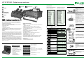
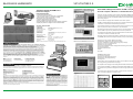
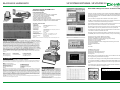
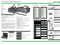
VIP SYSTEM3 - Digital energy analyzers Volt Amp P.F., cosØ kW kVA kvar Average power Maximum power Hz Distortion kWh kvarh approved (CESI approved) PRINTOUTS Timed local printout (automatic) up to max. 4 parameters SPECIFICATIONS Plotter printout of parameters selected by Printer - Plotter Manual PRINT-OUT of measurements shown on DISPLAY Overall manual PRINT-OUT of all the latest measurements available. Automatic PRINT-OUT of parameters selected by the operator at preset time intervals. Automatic PRINT-OUT at shorter intervals within preset time bands. PLOTTER PRINT-OUT in bar-graph form showing trends of two parameters selected by operator. Immediate PRINT-OUT of measurements when values cross minimum and maximum alarm thresholds preset by operator. More frequent PRINT-OUT of selected parameters while it remains in alarm state. PRINT-OUT of micro-interruptions and interruptions in line power. 82 instruments in 1 For unbalanced three-phase systems POWER SUPPLY Mains: 230 ± 10% at 50 Hz or 60 Hz Internal: Rechargeable Ni-Cd battery Performs: Manual Print-out of the display, General Printout (printout of SET UPs, alarms printout, timed printout in alarm state.) Pag.2, 3, 4 Pag.1 MEASUREMENT ON DISPLAY PAGES Volt Amp Power factor of the 3-phase system kWatt Volt Amp Active power of the three-phase system True voltage value of phase L1 (pag.2),L2 (pag.3), L3 (pag.4) True current value of the phase L1 (pag.2), L2 (pag.3), L3 (pag.4) Power factor Phase L1 (pag.2), L2 (pag.3), L3 (pag.4) Active Power phase L1 (pag.2), L2 (pag.3),L3 (pag.4) True value of the voltage betwen the phases (line voltage) P.F. cosØ kWatt A- N Hz Ist. W Med. W Max W CONF.10-CARTA-X-VIP3 Package of 10 paper rolls NASTRO-EPR-ERC-09C Ink ribbon for printer CONF.10-FUS-VIP3-220V Package of 10 - 5x20 - 80 mA - 250V - delayed fuses CONF.10-FUS-VIP3-110V Package of 10 - 5x20- 160 mA - 250V - delayed fuses VIP3-CAVO-VOLT Set voltage cables for VIP3 VIP3-CAVO-RETE Mains supply cable MICROVIP-BRETELLA 1 carryng strap for MICROVIP and VIP3 SYS3-VALIGIA-R6-ALL 1 Case for SYSTEM3 KIT Pag.8 Clamp meter 1000/A1VAC Max VA Med. var Max var Ist. % Pag.9 Kit complete with: 1 carrying case SYSTEM3 KIT 1 VIP SYSTEM3 ENERGY ANALYZER 1 power supply cable 1 Set of voltage measurement cables 3 Clip-on CTs 1000A/1 Vrms AC with cables 2 Fuses 5x20 160 mA (spare) 1 Ink ribbon 2 Rolls of printer paper (spare) 1 Carrying strap 1 User manual 1 Guarantee certificate 1 VIP UTILITIES 2.0 software 1 Calibration certificate PINZA-1000A/1V-AC Med. VA Ist. var Med. % Max % Pag.10 SPARE PARTS VIP-SYSTEM3-KIT 36 Pag.7 Ist. VA VIP-SYSTEM3 KIT True line voltage value (average of the three phases) True equivalent current value for the three-phase system P.F. cosØ V-12,V-23,V-31 Pag.5 The VIP-SYSTEM3 is a portable, lightweight analyzer with built-in printer which takes measurements on the three phases and calculates the equivalent three-phase values. The VIP-SYSTEM3 measures and prints voltages, currents, power levels, cosø and waveform distortion. It measures total and time-band energy consumption. Alongside instantaneous measurement readings it also provides average values and records maximum power and distortion readings. The built-in printer can provide print-out of parameter trends and alarm states in graph form. The VIP SYSTEM 3, with the addition of a MEMORY PACK, stores all measured data for later use. The MEMORY PACK can be used to program and carry out automatic measurement surveys, with the option of data transfer to a Host Computer or Remote Printer. A BLACK BOX can be inserted to expand the VIP SYSTEM 3's operating possibilities, including new functions such as monitoring of leakage, temperature, etc. The analyzer is therefore equipped with an input for auxiliary parameters and compartments for the MEMORY PACK and BLACK BOXES. It uses a "SUPER TWISTED" luminous display. GENERAL SPECIFICATIONS Inputs Voltages L1 - L2 - L3 - N: 600 Volt AC between phase and neutral at 20 ÷ 1000 Hz; or 600 Volt CC. Currents L1 - L2 - L3: 1 Volt AC at 20 ÷ 1000 Hz; or 1 Volt CC Auxiliary: AUX 1V/1mA Overload of voltage inputs: Max 720 Vrms - Surge voltage 1200 Volt (a cut-out is tripped at 720 Vrms) Overload of current inputs: 5 times full scale value (with cut-out tripped at limit values) Number of scales: 4 voltage scales 4 current scales Automatic scale change Scale change response time: 1 sec. Relay outputs: 2 - Type A - Contacts for 30 Volt / 0,5 A / 10 W Instrument dimensions: 240 x 220 x 115 mm. Weight 2.250 Kg. Ambient temperature range: +5°C +40°C Safety reference standards: IEC 348, VDE 411 class 2, for operating voltages 650 VAC rms, IEC 1010-1, EN 61010-1, 600V. EMC reference standards: EN 50081-1, EN 50082-1, EN 55022. Pag.6 Measurements in AC and DC Built-in printer for measurements, alarms and microinterruptions Graphic representation of measurements 2 relay alarm outputs RS232 output High accuracy (class 0,5) Automatic measurement CAMPAIGNS programmed and stored on MEMORY PACK Expandable to other measuring functions using special BLACK BOXES MEASUREMENTS at low and medium voltage Single-phase MEASUREMENTS MEASUREMENTS ON 3-wire and 4-wire three-phase systems MEASUREMTS on each phase and corresp. 3-phase measuremts. MEASUREMTS on DC systems using special clamp meter provided MEASUREMENTS of current value from 30 mA to 999 kA kWh kvarh CosØ TgØ True neutral current vaue V cosø FASE Ý (3ø) A W V cosø FASE L1 (R) A W V-12 A- N V-23 V-31 Hz Frequency Instantaneous, average and maximum active power of each phase and of the three-phase system. (Average values are assessed over an interval of 1 to 99 minutes preset by the operator.) Fase L1 (R) L2 (S) L3 (T) Ý (3ø) Ist. W W W W Med. W W W W Max W W W W Instantaneous, average and maximum active power of each phase and of the three-phase system. (Average values are assessed over an interval of 1 to 99 minutes preset by the operator) Fase L1 (R) L2 (S) L3 (T) Ý (3ø) Ist. VA VA VA VA Med. VA VA VA VA Max VA VA VA VA Instantaneous, average and maximum reactive power of each phase and of the three-phase system. (Average values are assessed over an interval of 1 to 99 minutes preset by the operator) Fase L1 (R) L2 (S) L3 (T) Ý (3ø) Ist. var var var var Med. var var var var Max var var var var Instantaneous, average and maximum distortion of each phase and of the three-phase system. (Average values are assessed over an interval of 1 to 99 minutes preset by the operator) Fase L1 (R) L2 (S) L3 (T) Ý (3ø) Ist. % % % % Med. % % % % Max % % % % Active power consumption for each phase and for three-phase system. Reactive power consumption for each phase and for three-phase system. Average power factor for each phase and for thre-phase system. Correspondent of average power factor, TgØ = kvarh/kWh Fase L1 (R) L2 (S) L3 (T) Ý (3ø) kWh kvarh Cosø Tgø The working day is divided into TIME BANDS programmed by the operator to provide separate measurements of power consumed at different tariffs. IMMEDIATE PRINT-OUT if average power values for a TIME BAND pass maximum alarm threshold. TWO OUTPUT RELAYS activated when selected parameters pass a preset maximum or minimum alarm threshold. PROGRAMMABLE RS232 SERIAL OUTPUT: - For connection to remote printer - for (on line) connection to HOST COMPUTER for storage and processing of measured data. For connection (by MODEM) to a tele-phone network for connection to remote Computer or Printer. OPTION of MEMORY PACK for automatic measurement surveys, with recording of data for all parameters. OPTION of modifying instrument functions using BLACK BOXES. OPTION of measurement, print-out and alarm monitoring of auxiliary parameters using BLACK BOXES. OPTION of connection (by MODEM) to switch-over telephone network for connection to computer. 4 additional pages are available only if the time bands are programmed (differentiated tariff bands). The data is displayed as on P. 10, with the writing F.T.1, F.T.2, F.T.3, F.T.4, instead of Phase. 37