1
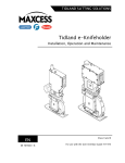
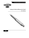
TIDLAND WINDING SOLUTIONS Tidland Narrow Web Shaft User Manual 3" GN 3" GH EN MI 556500 1 J IMPORTANT SAFETY INSTRUCTIONS When using this Tidland product, basic safety precautions should always be followed to reduce the risk of personal injury. Your company's safety instructions and procedures should always be followed. When using this product with any other equipment or machinery, all safety requirements stipulated by that equipment or machinery manufacturer must be followed. Compliance with local, state, and federal safety requirements is your responsibility. No part of these or the following instructions should be construed as conflicting with or nullifying the instructions from other sources. Be familiar with the hazards and safety requirements in your work environment and always work safely. Read and understand all instructions and shaft design application limits before operation. Never use this product for a purpose or in a machine that it was not specifically designed for. See Product Safety Data Sheet (PSDS). Do not exceed the operation loads for this shaft as noted on its PSDS, Product Safety Data Sheet. Follow all warnings and instructions marked on the product and on the PSDS. Do not use fingers or other objects to deflate the shaft; Tidland recommends using the Tidland Air Release Tool (see page 3). Inspect the shaft for wear and/or other safety and functional deficiencies daily, before each use. Wear safety glasses or proper eye protection when inflating or deflating or otherwise operating the air system. Do not remove or otherwise alter any setscrews or fastening devices prior to using this product. Do not operate this product if any setscrews or fastening devices are missing. Do not lift shaft manually if it is beyond your capacity. Loads over 1/3 your body weight may be prohibitive. Consult your company safety policy. When lifting a shaft, use proper lifting techniques, keeping back straight and lifting with the legs. Do not carry or lift this product over wet or slippery surfaces. Use appropriate mechanical lifting devices, such as a hoist or shaft puller, for heavier shafts. When performing maintenance or repair procedures, do not pressurize the shaft if journal setscrews are loose or missing. When performing maintenance procedures, do not pressurize the shaft if the journal is missing. All replacement parts used on this product should be made to original Tidland specifications. All maintenance and repair procedures performed on this product should be done to Tidland specifications by qualified personnel. www.maxcessintl.com Tidland GH/GN Narrow Web Shaft MI 556500 1 J Page 2 of 8 TABLE OF CONTENTS Important Safety Instructions ................................................................................................................... 2 Tidland Customer Service ....................................................................................................................... 3 Recommended Tools .............................................................................................................................. 3 Shaft Care................................................................................................................................................ 4 Assembly Diagram and Parts List ........................................................................................................... 4 Operation ................................................................................................................................................. 5 Install Shaft.......................................................................................................................................... 5 Install Corestop ................................................................................................................................... 5 Inflate Shaft ......................................................................................................................................... 5 Deflate Shaft to Remove Cores .......................................................................................................... 5 Maintenance ............................................................................................................................................ 5 Remove the External Element ............................................................................................................ 5 Remove the Bladder ........................................................................................................................... 5 Install the Bladder and External Element ............................................................................................ 6 Check for Leaks .................................................................................................................................. 7 Reinstall Nose Cone (GN Shafts only) ................................................................................................ 7 Troubleshooting ....................................................................................................................................... 7 CAUTION Wear eye protection when using compressed air. Keep the shaft operating pressure above 80 psi (5.4 bar) to ensure optimum safety and performance. Do not inflate or deflate the shaft while it is spinning. Use only the specified Tidland air tools to inflate or deflate the shaft. NOTICE Petroleum-based lubricants will damage the bladders and o-rings. Do not use! TIDLAND CUSTOMER SERVICE 1.360.834.2345 1.800.426.1000 www.maxcessintl.com RECOMMENDED TOOLS Clean, non-lubricated air supply: 80-120 psi (5.4-8.2 bar) for proper operation. Hex drive wrench kits: English and metric Inflation Tool (Tidland Part No. 128052, with gauge or 128054, without gauge) Air Release Tool (Tidland Part No. 111630) Hole Punch Guide: green (Tidland Part No. 577981) or yellow (Tidland Part No. 647597), determined by which element end clamp is installed on your shaft. See page 6. Hole Punch Tool, 1/8” (Tidland Part No. 760668) LOCTITE™ 222 (if not using patchlock screws) LOCTITE™ 243 (if not using patchlock screws) Crown® 8035 Slixit silicone dry spray lubricant (optional) For more accessories to help with your winding processes, visit www.maxcessintl.com. www.maxcessintl.com Tidland GH/GN Narrow Web Shaft MI 556500 1 J Page 3 of 8 SHAFT CARE During operation, use compressed air to keep shaft free from dust and debris. Sticky residue may be wiped from the shaft using a soft cloth and a mild solvent such as rubbing alcohol. Keep shaft dry and free of scratches and burrs that can damage cores. Do not use petroleumbased solvents on the shaft: these can damage rubber elements. ASSEMBLY DIAGRAM AND PARTS LIST GN shaft components are shown here. GH shaft is designed to fit over a base shaft and requires no journals. Valve locations vary, which may require the use of internal air hoses. INSTALLATION SET SCREWS 561655 GH SHAFT EXTERNAL ELEMENT RUBBER 503911 OR - ALUMINUM STRIP 587827 BLADDER 576711 GN SHAFT CORE STOP 564239 AIR FITTING 562024 ELEMENT END CLAMP ASSEMBLY (NOTE PROFILES BELOW) NOSE CONE (OR JOURNAL) JOURNAL SET SCREWS 561655 (GN SHAFT ONLY) SHAFT BODY HOSE FITTING 132366 O-RINGS (2 PLCS) 536190 CORESTOP ASSEMBLY (OPTIONAL) 564239 ELEMENT END CLAMP PROFILES On shafts prior to Serial No. 705657 VALVE END ASSEMBLY TOP BLOCK 654098 BOTTOM BLOCK 654100 SET SCREWS 564803 (M4) NON-VALVE END ASSEMBLY TOP BLOCK 654098 BOTTOM BLOCK 654099 SET SCREWS 564803 (M4) Torque set screws to 10-12 in∙lbs (1.1-1.4 Nm) www.maxcessintl.com Tidland GH/GN Narrow Web Shaft On shaft Serial No. 705657 and after VALVE END AND NON-VALVE END 697485 TOP BLOCK 697450 BOTTOM BLOCK 564144 SET SCREW (M8) Torque set screw to 25-30 in∙lbs (2.8-3.4 Nm) MI 556500 1 J Page 4 of 8 OPERATION Install Shaft GN: Install shaft on machine as required for your application. GH: Slide shaft over base shaft and tighten set screws to 30-35 ft·lbs (40.7-47.5 Nm). CORE STOP Install Corestop 1. Loosen – do not remove – the flat head cap screw in the top piece of the core stop. 2. Slide the dovetail into the groove in the shaft until it is aligned as required for your application. 3. Tighten the cap screw to 25-30 in·lbs (2.8-3.4 Nm). Inflate Shaft 1. 2. 3. 4. 1. Install core on the shaft. Connect air hose to a convenient dry, non-lubricated air source. Push the air nozzle of the Tidland inflation tool firmly into the valve receiver. Inflate the shaft until the air gauge indicator registers a minimum of 80 psi (5.4 bar). Caution: Do not exceed the maximum air pressure of 120 psi (8.3 bar). Deflate Shaft to Remove Cores 1. Use the Tidland Air Release Tool to depress the quick release air valve. 2. When the shaft is completely deflated, remove or reposition the core. MAINTENANCE Remove the External Element 1. Deflate shaft and/or disconnect air supply. It is not necessary to remove the nose cone or journals. 2. Loosen – do not remove – the set screw(s) in the element end clamps at both ends of the shaft. a. If the clamp has one set screw, slide the clamp out from the end of the shaft. b. If the clamp has two set screws, twist clamps 90° and slide or lift them out of the shaft. 3. Pull the external element from the shaft slot. ELEMENT END CLAMP AND SET SCREW(S) (CONFIGURATIONS VARY) ELEMENT AIR FITTING BLADDER Remove the Bladder 1. Carefully unseat the air fitting from the air inlet hole in the shaft slot. 2. Remove the bladder from the slot. 3. Remove the air fitting from the bladder and set aside for reuse. Be careful not to damage the air fitting. www.maxcessintl.com Tidland GH/GN Narrow Web Shaft MI 556500 1 J Page 5 of 8 MAINTENANCE Install the Bladder and External Element Bladder and rubber element material supplied for replacement will be longer than the required finished length. Do not cut to length until instructed. Aluminum strips are shipped cut to length. If not using patchlock screws, Tidland recommends using LOCTITE™ 222 on end clamp fasteners. If your element end clamp has one set screw (On shafts as of S/N 705657). 1. Cut the bladder 1.36" longer than the rubber element; ends must be cut square. 2. Using the Tidland Hole Punch Guide (yellow) and Hole Punch Tool, punch a hole through one wall of the new bladder at one end only. 3. Insert the air fitting into the bladder; install fitting into the air inlet in the shaft slot and install the bladder along the length of the shaft slot. 4. Remove the set screw from one element end clamp. Apply a small amount of LOCTITE 222 to the threads. Reassemble the clamp and install it in the slot. .460" YELLOW GUIDE .440" GREEN GUIDE The clamp should not extend past the end of the shaft. 5. Tighten to 25-30 in∙lbs (2.8-3.4 Nm). 6. Cut the new rubber element exactly 2.00" shorter than the shaft slot; ends must be cut square. 7. Grasp the excess bladder material firmly while feeding the rubber element into the slot until it contacts the valve end clamp. (If necessary, use a dry silicone spray lubricant to ease installation.) Do not stretch the bladder material. Note: When rubber element is installed, there should be .680" of bladder material left exposed. 8. Remove the set screw from the element end clamp at the valve end. Apply a small amount of LOCTITE 222 to the threads. Reassemble the clamp and install it in the slot. The clamp should not extend past the end of the shaft. Tighten set screw to 25-30 in∙lbs (2.8-3.4 Nm). 9. The element must be secured by the ridge on the bottom side of the clamp, but must not extend too far underneath. See illustration A. 10. Rubber elements: Chamfer both ends of the element. See illustration B next page. A. If your element end clamp has two set screws (up to S/N 705657). 1. Do not cut bladder to length until all parts are installed as follows. 2. Using the Tidland Hole Punch Guide (green) and Hole Punch Tool, punch a hole through one wall of the new bladder at one end only. 3. Insert the air fitting into the bladder; insert the air fitting into the air inlet in the shaft slot and install the bladder along the length of the slot. 4. Remove the two setscrews from the valve end element end clamp. (See end clamp profiles on page 4.) Apply a small amount of LOCTITE 222 to the threads. 5. Reassemble the clamp, install the clamp in the slot and tighten to 10-12 in·lbs (1.1-1.4 Nm). Clamp should be flush with the end of the shaft. Do not cut the excess bladder yet. 6. Measure the length of the slot: cut the new element exactly 1.25" shorter than the slot. Make sure to cut square across the ends of the element. (Aluminum strip elements are shipped cut to length.) 7. Grasp the excess bladder material firmly and hold it while feeding the rubber element into the slot until it contacts the valve end clamp. Do not stretch the bladder material. (If necessary, use a dry silicone spray lubricant to ease installation.) Remove the two setscrews from the remaining element end clamp. Apply a small amount of LOCTITE 222 to the threads. Reassemble the clamp, install the clamp in the slot and tighten to 10-12 in·lbs (1.1-1.4 Nm). Make sure the end clamp covers at least 50% of the air fitting head area and does not extend past the end of the shaft. 8. Trim the remaining bladder material flush against the end of shaft and end clamp. 9. Rubber elements: Chamfer both ends of the element. See illustration B next page. Continued next page www.maxcessintl.com Tidland GH/GN Narrow Web Shaft MI 556500 1 J Page 6 of 8 MAINTENANCE For rubber elements only: Chamfer both ends of the element. See illustration B. Note: Element end clamp profiles may vary, but the chamfer requirements are the same for all. B. Check for Leaks 1. 2. 3. 4. Check for leaks by filling the bladder to 5-10 psi (.35-.7 bar). Spray end clamps and valve area with soapy water and look for bubbles that may indicate a leak. If there are any air leaks, check that the end clamps and valve are tight. Remove excess soapy water when test is completed. Reinstall Nose Cone (GN Shafts only) 1. Push nose cone into shaft body as far as it will go. 2. Apply small amount of LOCTITE 242 to threads of set screws and tighten to 55-60 in·lbs (13.6-20.3 Nm). TROUBLESHOOTING Problem Possible Cause Recommended Solution Air Leak Element end clamps not tight Tighten end clamps at both ends of shaft: see torque specs for your clamps on page 4. Ensure that the end clamps completely cover the end of the bladder. Bladder must be cut square across its end in order for the end clamp to make contact across the full width of the bladder. Loosen the clamp and slide it into the shaft slot until the outside edge is flush with the outside end of the shaft. Inspect bladder length under element end clamp. If it is too long, you may not be able slide the clamp. Trim slightly and reinstall clamp. Ensure that the valve end clamps cover at least 50% of the air fitting head area. End clamps not centered over bladder Element end clamps extending past shaft O.D. End clamps not covering the air fittings properly Hole for air fitting in bladder is deformed Air hose connection to the air fitting has failed. Valve is leaking Ruptured bladder Remove end clamp and check the bladder around the air fitting. If the hole is deformed or the bladder is torn, replace the bladder. Use the Tidland Hole Punch Tool and Hole Punch Guide for best results when installing air fittings in a new bladder. Remove end clamps and confirm that the air fitting is connected to the internal air hose. Check that the fitting is seated correctly in its hole. Access the valve and confirm that air hoses are attached. If valve is leaking from the center, replace the valve. Remove external element and inspect bladder for cracks. Continued next page www.maxcessintl.com Tidland GH/GN Narrow Web Shaft MI 556500 1 J Page 7 of 8 TROUBLESHOOTING continued) Problem Possible Cause Recommended Solution External element will not collapse completely Fiber or dust buildup in element slot is causing scraping along edges of slot Clean along slot. If necessary, remove and replace external element and bladder. Cold flow of rubber element Replace rubber element and bladder. Kinked hoses Check hose installation. Elements difficult to install Buildup in slot Clean slot with mild non-petroleum based solvent and dry thoroughly. Spray slot and elements with dry silicone lubricant. External element extrudes out of slot Element is over-lubricated with dry silicone spray. Remove element and wipe clean. Reinstall, lubricating only as necessary. Core will not fit on shaft Bladder too long and pushing up on element end clamp. Bladders that are too long may push up on clamp preventing it from seating properly. Trim small amount from bladder and reinstall clamp, making sure that the end of the bladder is secure under the ridge of the clamp. Core is slipping Elements not gripping core Check inflation pressure. Ensure that the external element is expanding completely. Check for leaks. Check for worn elements. Ensure correct core size.* NORTH, CENTRAL AND SOUTH AMERICA EUROPE, MIDDLE EAST AND AFRICA CHINA Tel +1.360.834.2345 Fax +1.360.834.5865 [email protected] www.maxcessintl.com Tel +49.6195.7002.0 Fax +49.6195.7002.933 [email protected] www.maxcess.eu Tel +86.756.881.9398 Fax +86.756.881.9393 [email protected] www.maxcessintl.com.cn INDIA JAPAN KOREA, TAIWAN, AND SE ASIA Tel +91.22.27602633 Fax +91.22.27602634 [email protected] www.maxcess.in Tel +81.43.421.1622 Fax +81.43.421.2895 [email protected] www.maxcess.jp Tel +65.9620.3883 Fax +65.6235.4818 [email protected] © 2013 Maxcess