1
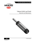
TIDLAND WINDING SOLUTIONS Tidland External Element Shaft User Manual EN MI 651853 1 T Series 800 GL External Element GE External Element GX Ultra-Lightweight External Element Series 850 GS Spiral External Element TABLE OF CONTENTS Important Safety Instructions ................................................................................................................... 3 Assembly Diagram and Part Identification .............................................................................................. 4 Installation................................................................................................................................................ 5 Core Stops .......................................................................................................................................... 5 Operation ................................................................................................................................................. 5 To Inflate Shaft .................................................................................................................................... 5 Maintenance ............................................................................................................................................ 6 General Information ............................................................................................................................ 7 Replacing Rubber External Element ................................................................................................... 8 Replacing Rubber External Element with Folded Bladder ................................................................ 10 Replacing Aluminum External Element and Bladder ........................................................................ 12 Replacing Valves .............................................................................................................................. 14 Non-Isolation Quick Release ........................................................................................................ 14 Isolation Valve (3-way or 4-way)................................................................................................... 14 Air Circuits ......................................................................................................................................... 15 Troubleshooting ..................................................................................................................................... 16 Spare Parts ............................................................................................................................................ 18 Element End Clamps ........................................................................................................................ 18 Valves ................................................................................................................................................ 18 Core Stops ........................................................................................................................................ 19 Hole Punch Guides ........................................................................................................................... 19 Miscellaneous.................................................................................................................................... 19 Mini GL Shafts ....................................................................................................................................... 20 CAUTION Wear eye protection when using tools or compressed air. Follow all shaft safety precautions (page 3). Petroleum-based products will damage bladders and rubber elements – DO NOT USE. TIDLAND CUSTOMER SERVICE 1.360.834.2345 www.maxcessintl.com For repair and warranty information, visit www.maxcessintl.com/repairs RECOMMENDED TOOLS Tidland Inflation Tool (P/N 128052) Tidland Air Release Tool (P/N 111630) Tidland Hole Punch Tool (See Miscellaneous, page 19) Tidland Hole Punch Guides (See page 19) Hex wrenches: 3 mm, 4 mm, 1/8" Thin wall socket wrench: 7/16", 3/4" (may be required during valve replacement) LOCTITE™ 222 (if not using patchlock screws) ® AERVOE Crown 8035 Slix-it silicone spray (or equivalent) www.maxcessintl.com Tidland External Element Shaft MI 651853 1 T Page 2 of 20 IMPORTANT SAFETY INSTRUCTIONS When using this Tidland product, basic safety precautions should always be followed to reduce the risk of personal injury. Your company's safety instructions and procedures should always be followed. When using this product with any other equipment or machinery, all safety requirements stipulated by that equipment or machinery manufacturer must be followed. Compliance with local, state, and federal safety requirements is your responsibility. No part of these or the following instructions should be construed as conflicting with or nullifying the instructions from other sources. Be familiar with the hazards and safety requirements in your work environment and always work safely. 1. Read and understand all instructions and shaft design application limits before operation. 2. Never use this product for a purpose or in a machine that it was not specifically designed for. See Product Safety Data Sheet (PSDS). 3. Do not exceed the operation loads for this shaft as noted on its PSDS, Product Safety Data Sheet. 4. Follow all warnings and instructions marked on the product and on the PSDS. 5. Inspect the shaft for wear and/or other safety and functional deficiencies daily, before each use. 6. Wear safety glasses or proper eye protection when inflating or deflating or otherwise operating the air system. 7. Do not remove or otherwise alter any setscrews or fastening devices prior to using this product. 8. Do not operate this product if any setscrews or fastening devices are missing. 9. Do not lift shaft manually if it is beyond your capacity. Loads over 1/3 your body weight may be prohibitive. Consult your company safety policy. 10. When lifting a shaft, use proper lifting techniques, keeping back straight and lifting with the legs. 11. Do not carry or lift this product over wet or slippery surfaces. 12. Use appropriate mechanical lifting devices, such as a hoist or shaft puller, for heavier shafts. 13. When performing maintenance or repair procedures, do not pressurize the shaft if journal setscrews are loose or missing. 14. When performing maintenance procedures, do not pressurize the shaft if the journal is missing. 15. All replacement parts used on this product should be made to original Tidland specifications. 16. All maintenance and repair procedures performed on this product should be done to Tidland specifications by qualified personnel. When using chucks on this shaft, always locate chucks as shown. Improper placement of chucks will reduce life cycle of the shaft. Questions about installation, application or load calculations? Call Tidland Customer Service. www.maxcessintl.com Tidland External Element Shaft MI 651853 1 T Page 3 of 20 ASSEMBLY DIAGRAM AND PART IDENTIFICATION Tidland Series 800/850 shafts are available in many configurations. See Spare Parts at the end of this publication for more information about part numbers specific to your model. Please have your serial number available when you contact Tidland Customer Service. This publication covers installation, operation and maintenance for the following products: Series 800 GL External Element GE External Element GX Ultra-Lightweight External Element Series 850 GS Spiral External Element SOC HD CAP SCREWS w/ PATCH-LOCK M5 X 0.8 X 14 MM LG ELEMENT END CLAMP EXTERNAL ELEMENT (RUBBER OR ALUMINUM STRIP) STEEL STRIP (SEGMENTED STRIP OPTION) OPTION: SEGMENTED ALUMINUM STRIP (WAVE SPRINGS NOT SHOWN) BLADDER JOURNAL AIR FITTING HEAD SHAFT BODY AIR FITTING BARB T-SLOT OR SNAP-IN EXTRUSION HEAD JOURNAL AIR VALVE QUICK RELEASE OR ISOLATION SIDE OR END LOCATION Bladder end clamps vary by shaft model and serial number. See Spare Parts at the end of this publication or call your Tidland Customer Service Representative for part numbers. Please have your serial number ready when you call. The one-piece external element configuration is obsolete for the Series 800/850. Tidland can help you update your shaft to the new design that uses a separate polyurethane bladder and external element. www.maxcessintl.com Tidland External Element Shaft MI 651853 1 T Page 4 of 20 INSTALLATION Install the shaft as required for your application. Core Stops There are many configurations for the Tidland Series 800/850 shafts, some of which include core stops. Basic core stop installation is covered below. Call Customer Service for part numbers if you need replacement parts. Fig. 1 – Core Stop (Dovetail): Loosen – do not remove – the two socket head capscrews in the top piece of the core stop. Slide the dovetail into the groove in the shaft until it is aligned as required for your application. Tighten the bolts to 55-60 in·lbs. Fig. 1 Fig. 2 – Core Stop (Ring): Loosen – do not remove – the socket head bolt in the core stop ring until the ring can slide over the shaft. Make sure the seam in the ring is not aligned directly over a rubber element. Position the ring along the shaft as required for your application, then tighten the bolt to 55-60 in·lbs. Fig. 2 OPERATION To Inflate Shaft Use only the Tidland Inflation Tool. 1. Push the air nozzle firmly into the valve receiver, which will depress both the valve button and the tip of the inflation tool. 2. Inflate the shaft until the line pressure air gauge indicates a minimum of 80 psig (5.5 bar). Do not exceed the maximum air pressure of 120 psig (8.2 bar). Note: Keep the shaft pressure above 80 psig (5.5 bar) to ensure optimal safety and performance. Do not inflate while the shaft is rotating. To deflate, only use the Tidland air release tool. Do not use finger to release air. Do not deflate while the shaft is rotating. To Deflate Shaft 1. Using the air release tool, push in the quick release air valve and allow the air to escape through the hole in the center of the button. 2. Remove the shaft from the roll/core. www.maxcessintl.com Tidland External Element Shaft MI 651853 1 T Page 5 of 20 MAINTENANCE The Tidland Series 800/850 shafts come in many configurations. Maintenance procedures are similar for each model. Specific part numbers are on page 18. IF YOU HAVE THIS ELEMENT CLAMP USE INSTRUCTIONS ON Page 8 with a rubber element with folded bladders OR a one-piece rubber element (no bladder) * Page 10 * The one-piece configuration is obsolete. Call Tidland for assistance to update your shaft to the new design. Page 12 with an aluminum strip element Page 20 "Mini GL Shafts" with 7/16" wide element Keep shaft clean and free from grit and scratches. The external rubber element and the bladder underneath it can be replaced without removing the shaft from the machine. Do not remove the aluminum T-slot extrusion from the shaft when replacing external element and bladder. To check for leaks after replacing bladders and elements, inflate shaft to operating pressure, spray end clamps with soapy water and check for bubbles. Read page 7 for important general information about replacing shaft elements. www.maxcessintl.com Tidland External Element Shaft MI 651853 1 T Page 6 of 20 MAINTENANCE General information for working with external elements See complete instructions for your element type: Rubber Element, page 8; Folded Bladder, page 10; Aluminum Strips, page 12. Fig. 3 - Fig. 4 Fig. 5 - The Tidland Series 800/850 External Element shafts are fitted with two different element end clamps. One clamp is for the non-valve end and the other has a recess that accommodates the air fitting at the valve end. The clamps are not interchangeable from end to end. Element end clamps with UHMW strip must be used on spiral strip shafts. Use these end clamps ONLY for bladders that are folded over the air fitting. NON-VALVE END VALVE UHMW STRIP NON-VALVE END VALVE BOTTOM VIEW TOP Fig. 3 Fig. 6 Fig. 7 Fig. 8 - FOR FOLDED BLADDERS ONLY BOTTOM VIEW BOTTOM Fig. 4 Fig. 5 Cut bladders and elements square across the ends so there is a flush fit at the end clamp. Bladders cut at an angle are at risk for leaks. Use the Tidland Hole Punch and Tidland Hole Punch Guide to punch holes for air fittings in the bladder. Punch the hole in one wall only of the bladder. Make sure that the element end clamps completely cover the ends of the bladders. Using the correct Hole Punch Guide will ensure that the bladder ends are long enough to be secured under the end clamps. HOLE PUNCH TOOL BLADDER Fig. 6 Fig. 9 - HOLE PUNCH GUIDE Fig. 7 Fig. 8 If the barbed end of the air fitting comes out of the port and detaches from the air hose, there is a risk of the hose falling back inside the shaft body. If the air hose is exposed, wrap a piece of tape around it as a precaution. Important: If at any time an air hose is pulled off an air fitting barb, note that the end of the air hose will be stretched or damaged. Do not reuse the hose without cutting off the damaged portion. Fig. 9 Tidland recommends the use of Loctite 222 on screw threads or a patch-lock type screw for the element end clamps. www.maxcessintl.com Tidland External Element Shaft MI 651853 1 T Page 7 of 20 MAINTENANCE To Replace Rubber External Element and Bladder (Straight or Spiral) Tidland recommends replacing external element and bladder at the same time. Old bladders deformed by cold flow inhibit the insertion of the external element. Before replacing shaft components, refer to page 7 for general information to aid in leak-free operation. The one-piece rubber element is obsolete. Tidland can help you update your shaft to the new design that uses a separate polyurethane bladder and external element. Remove the Rubber Element 1. Remove screws from end clamps and remove the clamps from each end of the shaft. 2. Pry up the rubber element and pull it from the slot. Remove the Bladder 3. Lift the bladder out of the slot, remove the air fitting head from the barb fitting in the slot. Use care: If the barb fitting comes off the hose, the hose can fall inside the shaft. 4. Remove the air fitting "head" from the bladder and set aside. 5. Clean the shaft and slot with a soft cloth. A rag damp with mild solvent, such as rubbing alcohol, is acceptable. NOTICE Petroleum-based products will damage bladders. Do not use. Install Bladder – Valve End Note: Bladder material supplied for replacement will be longer than the required finished length. Do not cut to length until Step 20. 6. Square off one end of the bladder. (Bladders cut at an angle are at risk for leaks.) 7. Insert the Tidland Hole Punch Guide (blue) into the end of the bladder. .38" Fig. 10 With the Tidland Hole Punch Tool, punch a hole in one wall only of the bladder. 8. Insert air fitting "head" into the hole in the bladder wall (Fig. 10). 9. Install the bladder along the length of the slot and connect the air fitting head with the barb half of the air fitting in the slot. 10. Install the valve end clamp, securing the bladder underneath it. 11. Using 4 mm hex wrench, tighten end clamp screws to 55-60 in·lbs. 12. IMPORTANT: At the non-valve end, with the bladder relaxed 0.140" in the slot, mark the bladder.140" inboard from the center of the screw holes. After the rubber element is installed, this mark should be visible at the same point, indicating that your bladder has not bunched up under the element or has not stretched. Fig. 11 TOP VIEW TOP VIEW BOTTOM VIEW BOTTOM VIEW VALVE END VALVE END USE WITH STRAIGHT EXTERNAL ELEMENTS (RUBBER OR ALUMINUM) USE WITH SPIRAL ELEMENTS (Continued on next page.) www.maxcessintl.com Tidland External Element Shaft MI 651853 1 T Page 8 of 20 MAINTENANCE Rubber External Element and Bladder – Straight or Spiral (continued) Note: Use silicone spray to ease installation of bladder and external elements, especially for longer shafts. Do not use petroleum-based lubricants. Install the Rubber Element – Valve End Rubber element material supplied will be longer than the required finished length. Do not cut to length until Step 18. 13. Square off one end of the rubber element. This will be the leading end for installation. 14. Spray the bladder in the slot and all sides of the new rubber element with silicone spray. 15. Starting at the non-valve end of the shaft slot, hold the loose end of the bladder material securely and begin to push the rubber element into the slot. Note: Do not stretch the bladder, but keep it taut under the rubber element. 16. Push and pull the rubber element (easier with two people) along the length of the slot until the leading end contacts the end clamp at the air end of the shaft. Apply silicone spray as needed to ease insertion and to prevent the bladder from bunching up under the element. If necessary, hold the rubber element with needlenose pliers, being careful not to damage the bladder. Note: For spiral shafts, the rubber element should slide over the top of the UHMW strip on the end clamp. 17. At the valve end, begin to push the element toward the clamp, working your way back along the length of the slot to the non-valve end. This will relieve stretching and slightly compress the element, significantly reducing the risk of the element "shrinking" away from the clamps during operation. 18. Holding the compression in the element, at the non-valve end, cut the element square at a point just inside the clamp pocket. Let the element relax; it should expand into the pocket. Install Bladder – Non-Valve End 19. At the non-valve end, the mark made on the bladder in Step 12 should be visible .140" from the screw hole edges. If not, then the bladder has contracted under the element or has stretched. You will need to remove or pull back the element in order to relax the bladder for proper installation. Repeat the procedure as needed to align the mark on the bladder. Use silicone spray liberally to ease installation of the elements. 20. Cut square across the end of the bladder at the mark. 21. Push the rubber element back from the clamp pocket into the slot and install the non-valve end clamp, securing the bladder underneath it. Note: For spiral shafts, always use the end clamp with the UHMW strip attached. The strip will be in between the bladder and the rubber element NON-VALVE when assembly is complete. END CLAMP BOTTOM VIEW 22. Using 4 mm hex wrench, tighten end clamp screws to 55-60 in·lbs. Install Rubber Element – Non-Valve End RUBBER ELEMENT 23. After all elements are installed inflate shaft to operating pressure. 24. With a grinder, carefully chamfer the ends of the element next to the clamps so that they fully collapse below the body O.D. when the shaft is deflated. Note: Make sure to chamfer clear to the end of the element To check for leaks after replacing bladders and elements, inflate shaft to operating pressure, spray end clamps with soapy water and check for bubbles. www.maxcessintl.com Tidland External Element Shaft END CLAMP MI 651853 1 T BLADDER Page 9 of 20 MAINTENANCE To Replace Rubber External Element with Folded Bladder Tidland recommends replacing external element and bladder at the same time. Old bladders deformed by cold flow inhibit the insertion of the external element. Before replacing shaft components, refer to page 7 for general information to aid in leak-free operation. Note: For easier, leak-free assembly, the folded bladder style can be updated to the non-folded, flat configuration by converting to a new end clamp. Call Tidland for assistance. Remove the Rubber Element 1. Remove screws from end clamps and remove the clamps from each end of the shaft. 2. Pry up the rubber element and pull it from the slot. 3. Inspect the element for wear; look for slits, gouges or grooves at the core ends. TOP AND BOTTOM VIEWS THIS CLAMP STYLE IS INTERCHANGEABLE FROM END TO END. Remove the Bladder 4. Lift the bladder out of the slot, carefully removing the air fitting from its port in the slot. 5. Remove the air fitting "head" from the bladder and set aside. 6. Clean the shaft and slot with a soft cloth. A rag damp with mild solvent, such as rubbing alcohol, is acceptable. NOTICE Petroleum-based products will damage bladders. Do not use. Install Bladder – Valve End Note: Bladder material supplied for replacement may be longer than the required finished length. Do not cut to length until Step 18. 7. Square off one end of the bladder. (Bladders cut at an angle are at risk for leaks.) 8. Insert the Tidland Hole Punch Guide (red) into the end of the bladder. With the Tidland Hole Punch Tool, punch a hole in one wall only of the bladder. 1.25" Fig. 12 9. Insert air fitting "head" into the hole in the bladder wall (Fig. 12). (ILLUSTRATION NOT TO SCALE) 10. Install the bladder along the length of the slot and connect the air fitting head with the other half of the air fitting in the slot. The excess length at the valve end will be folded back over the air fitting when the external element is installed. (Continued on next page.) www.maxcessintl.com Tidland External Element Shaft MI 651853 1 T Page 10 of 20 MAINTENANCE Rubber External Element with Folded Bladder (continued) Note: Use dry silicone spray to ease installation of bladder and external elements. Do not use petroleum-based lubricants. SHAFT SLOT 11. Square off the leading end of the rubber element. 12. At the non-valve end of the shaft slot, hold the loose end of the bladder material securely and RUBBER ELEMENT begin to push the rubber element into the slot. Caution: Do not stretch the .375" bladder, but keep it taut under the (9.5mm) rubber element. 13. Push and pull the rubber element along the length of the slot until the leading end is .375" (9.5mm) from the outside edge of the end clamp pocket. 14. Fold the end of the bladder back and tuck it underneath the rubber element. 15. Install the end clamp, securing the bladder and rubber element underneath it. 16. Using 4 mm hex wrench, tighten end clamp screws to 55-60 in·lbs. END CLAMP RUBBER ELEMENT AIR FITTING FOLD Install Bladder – Non-Valve End 17. At the non-valve end, cut the bladder to length .500" past the end of the shaft slot. 18. Cut the rubber element square .375" short of the end of the shaft slot. 19. Lift the end of the rubber element and fold the bladder back underneath. 20. Install the non-valve end clamp, securing the bladder and element underneath it. 21. Using 4 mm hex wrench, tighten end clamp screws to 55-60 in·lbs. BLADDER SHAFT SLOT RUBBER ELEMENT .500" (12.7mm) .375" (9.5mm) To check for leaks after replacing bladders and elements, inflate shaft to operating pressure, spray end clamps with soapy water and check for bubbles. www.maxcessintl.com BLADDER Tidland External Element Shaft MI 651853 1 T Page 11 of 20 MAINTENANCE To Replace Aluminum External Element and Bladder When replacing bladders, inspect aluminum elements for wear. Replace if necessary. Tidland recommends replacing external element and bladder at the same time. Old bladders deformed by cold flow inhibit the insertion of the external element. Before replacing shaft components, refer to page 7 for general information to aid in leak-free operation. Remove End Clamps 1. Remove screws from end clamps and remove the clamps from each end of the shaft. Remove Aluminum External Element 2. Grasp the wave springs at one end and pull them from the slot. 3. Pull the aluminum external element from the slot. 4. Inspect the element for wear; look for cracks or grooves. Remove the Bladder 5. Lift the bladder out of the slot, carefully removing the air fitting from its port in the slot. 6. Remove the air fitting "head" from the bladder and set aside. 7. Clean the shaft and slot with a soft cloth. A rag damp with mild solvent, such as rubbing alcohol, is acceptable. NOTICE Petroleum-based products will damage bladders. Do not use. Install Bladder – Valve End Note: Bladder material supplied for replacement may be longer than the required finished length. Do not cut to length until Step 17. 8. Square off one end of the bladder. (Bladders cut at an angle are at risk for leaks.) 9. Insert the Tidland Hole Punch Guide (blue) into the end of the bladder. With the Tidland Hole Punch Tool, punch a hole in one wall only of the bladder. .38" Fig. 13 10. Insert air fitting "head" into the hole in the bladder wall (Fig. 13). (ILLUSTRATION NOT TO SCALE) 11. Install bladder in slot and connect the air fitting head with the other half of the air fitting in the slot. 12. Install the valve end clamp, securing the bladder underneath it. 13. Using 4 mm hex wrench, tighten end clamp screws to 55-60 in·lbs. TOP VIEW BOTTOM VIEW VALVE END VALVE END USE WITH STRAIGHT EXTERNAL ELEMENTS (RUBBER OR ALUMINUM) USE WITH SPIRAL ELEMENTS (Continued on next page.) www.maxcessintl.com Tidland External Element Shaft MI 651853 1 T Page 12 of 20 MAINTENANCE Aluminum External Element and Bladder (continued) 14. Starting at the non-valve end of the shaft slot, hold the loose end of the bladder material securely and slide the aluminum external element into the slot until it contacts the end clamp at the valve end. Note: Do not stretch the bladder, but keep it taut under the aluminum strip. 15. Install the wave springs on top of each side of the aluminum external element (Fig. 14). ALUMINUM STRIP BLADDER Fig. 14 WAVE SPRING 0.140" Install Bladder – Non-Valve End 16. At the non-valve end, mark the bladder at a point 0.140" from the end clamp screw hole centers (Fig. 15). Do not stretch the bladder. 17. Cut square across the end of the bladder. 18. Install the non-valve end clamp, securing the bladder underneath it. 19. Using 4 mm hex wrench, tighten end clamp screws to 55-60 in·lbs. Fig. 15 NON-VALVE END CLAMP To check for leaks after replacing bladders and elements, inflate shaft to operating pressure, spray end clamps with soapy water and check for bubbles. www.maxcessintl.com Tidland External Element Shaft MI 651853 1 T Page 13 of 20 MAINTENANCE To Remove and Replace Valves There are several styles of valves used on the Tidland Series 800/850 shafts, installed either in the end or the side of the shaft, depending on your application. Ensure that the shaft is completely deflated before removing the valve. After removing a valve, remove damaged portion of air hoses before reconnecting them to the valve. To check for air leaks after reinstalling valves, inflate shaft to operating pressure, spray valve with soapy water and watch for bubbles. Non-Isolation Quick Release Thin wall socket wrench: 7/16", 3/4" (may be required) 1. Use a socket wrench to unscrew the valve from its side or end location in the shaft. 2. Apply thread sealant (according to manufacturer's instructions) to threads of new valve (unless the sealant is pre-applied) and reinstall. NOTE: Valves with pre-applied thread sealant are good for multiple uses. Always inspect the valve threads for sufficient sealant; do not reuse more than six times. Isolation Valve (3-way or 4-way) End or Side Location 1. Remove set screw. 2. Pull valve from shaft carefully and disconnect air hoses. 3. Cut off damaged ends of hoses. 4. Attach air hoses to new valve. 5. Reinstall valve in shaft. 6. Reinstall setscrew. Side Location Bolt-in 1. Remove socket head bolt. 2. Pull valve from shaft carefully and disconnect air hoses. 3. Cut off damaged ends of hoses. 4. Attach air hoses to new valve. 5. Reinstall valve in shaft. 6. Reinstall socket head bolt. Bolt-in side valve replaced with new valve and adapter. See Spare Parts, page 18. (April 2011) Before operation: Check for proper inflation and deflation. If there is a problem, check air hoses for kinks or disconnects. See Troubleshooting on page 16. www.maxcessintl.com Tidland External Element Shaft MI 651853 1 T Page 14 of 20 MAINTENANCE Air Circuits Air circuits vary in configuration for the Tidland Series 800/850 shaft designs. In most cases, the air fitting at the end of each external element (underneath the element clamp) attaches to a hose inside the shaft. For single circuit valves, internal hoses attach to separate barbs on a plug installed either in the journal or on the side of the shaft. Air is delivered through the valve to the plug. Some single circuit shafts have no hoses. Air is routed through drilled holes from valve to the air fitting under the rubber elements. Isolation valves connect directly to the internal air hoses. Maintenance for some air circuit hoses may require removal of shaft journals. Hoses may feed out the end of the shaft into the journal or out the side of the shaft, depending upon the type of valve used. Wrap a piece of tape around exposed hoses to prevent them from slipping back inside the shaft body. (Journal removal may be required to retrieve them.) After removing an air fitting, always clip off the damaged end of an air hose before reconnecting it to the fitting. Fig. 16a Fig. 16b Fig. 16 "T-barb" hose connections are made inside the shaft. The number of connections depends upon how many external elements the shaft has. All connections should be made from opposing pairs of hoses and reduced to the minimum number of pairs needed for the 3-way or 4-way valve used, as shown in Fig. 16a and 16b. Fig 17. Hoses originating from end clamps in the shaft "head" must feed back into the shaft body before feeding out through the end of the shaft (to prevent being crushed by the journal). Note: Check air flow through hoses during assembly. Hose kinking can prevent inflation or deflation. Fig. 17 www.maxcessintl.com Tidland External Element Shaft MI 651853 1 T Page 15 of 20 TROUBLESHOOTING See page 6 to determine which set of instructions to use for the Recommended Solution. To check for leaks after replacing bladders and elements, inflate shaft to operating pressure, spray end clamps with soapy water and check for bubbles. Problem Possible Cause Recommended Solution Air Leak Element end clamps not tight Tighten end clamps at both ends of shaft to 55-60 in·lbs. Use 29 in·lbs for the Mini GL Shafts. End clamps not centered over bladder Ensure that the end clamps completely cover the end of the bladder. Bladder must be cut square across its end in order for the end clamp to make contact across the full width of the bladder. End clamp with UHMW strip installed incorrectly. Spiral external element only – ensure that element end clamp with UHMW strip is installed between the bladder and the external element. Hole for air fitting in bladder is deformed Remove end clamp and check the bladder around the air fitting. If the hole is deformed or the bladder is torn, replace the bladder. Use the Tidland Hole Punch Tool and Hole Punch Guide for best results when installing air fittings in a new bladder. Air hose connection to the air fitting has failed. Remove end clamps and confirm that the air fitting is connected to the internal air hose. Check that the fitting is seated correctly in its hole. Valve is leaking Access the valve and confirm that air hoses are attached. If valve is leaking from the center, replace the valve. Ruptured bladder Remove external element and inspect bladder for cracks. Aluminum external element only – ensure that wave springs are correctly installed (Fig. 14, page 13). They should sit on top of the aluminum strip. www.maxcessintl.com Tidland External Element Shaft MI 651853 1 T Page 16 of 20 TROUBLESHOOTING Problem Possible Cause Recommended Solution External element will not collapse completely Fiber or dust buildup in element slot is causing scraping along edges of slot Clean along slot. If necessary, remove and replace external element and bladder. Cold flow of rubber element Replace rubber element and bladder. Wave springs installed incorrectly (aluminum external element style only) Wave springs must be installed along the top edges of the aluminum external element. Kinked hoses Check hose installation: Under element end clamps At valve In shaft body (may require journal removal) Elements difficult to install Buildup in slot Clean slot with mild non-petroleum based solvent and dry thoroughly. Spray slot and elements with dry silicone lubricant. External element extrudes out of slot Element is over-lubricated with dry silicone spray. Remove element and wipe clean. Reinstall, lubricating only as necessary. Core will not fit on shaft Element end clamps extending past shaft O.D. Inspect bladder length under clamp. If it is too long, it will push up on clamp. Trim small amount from bladder and reinstall clamp. Core is slipping Elements not gripping core Check inflation pressure. Ensure that the external element is expanding completely. Check for leaks. Check for worn elements. Ensure correct core size.* * Recommended core clearance on non-inflated shaft is less than .06" for maximum torque capacity. www.maxcessintl.com Tidland External Element Shaft MI 651853 1 T Page 17 of 20 SPARE PARTS Call Tidland Customer Service for assistance with choosing the correct replacement parts for your shaft. Please have the shaft serial number ready. (Parts not to scale.) Element End Clamps 674761 585572 585573 622198 622199 VALVE END NON-V END VALVE END NON-V END 586183 586184 VALVE END NON-V END Must use on spiral element shafts 133080 692484 133671 USED ON "MINI GL" SHAFTS 132445 Use only with the folded bladder design. Clamp is the same for valve and non-valve end. For easier, leak-free assembly, this clamp should be updated to the current non-folded style Valves ISOLATION 132403 703276 713308 Kit = 4-WAY, SIDE OR END 3-WAY, SIDE OR END 3-WAY, SIDE (replaces 132520) 703276 valve 713309 adaptor 130248 btn hd scr 133103 soc hd scr (replaces 133151 bolt-in side valve) SINGLE CIRCUIT www.maxcessintl.com 126475 126427 126440 QUICK RELEASE QUICK RELEASE QUICK RELEASE – MIDGET Tidland External Element Shaft MI 651853 1 T Page 18 of 20 SPARE PARTS Core Stops Call for replacement part number. 647911 w/ Soc Hd CpScr M6 x 1.00 x 8mm LG (2 ea) Hole Punch Guides If your shaft uses this element end clamp, you will need the blue Tidland hole punch guide. Part No. 577982 If your shaft uses this element end clamp, you will need the red Tidland hole punch guide. Part No. 577980 If your shaft uses this element end clamp, you will need the hole punch kit for Tidland "Mini" GL shafts. Part No. 538908 Miscellaneous Air Fitting, Head Air Fitting, Barb Air Hose, Poly, 1/8" OD x 1/16" ID, Blue Bladder, Polyurethane Deflation Tool External Element, Rubber External Element, Aluminum Hole Punch Tool Hole Punch Guide, for Folded Bladder only Hole Punch Guide, for Straight or Spiral Strip Hole Punch Kit, for Mini GL Shaft Inflation Tool Set Screw 1/4-20 (End Valves) Soc Hd CpScr (3-way Side Valve) Springs, Wave (specify length) T-Barb Hose Connectors www.maxcessintl.com 562024 516618 132556 576711 111630 503911 587827 760668 577980 (red) 577982 (blue) 538908 128052 Call Tidland 133103 617952 250501 Tidland External Element Shaft MI 651853 1 T Page 19 of 20 MINI GL SHAFTS SOC HD CAPSCR (CALL FOR P/N) EXTERNAL ELEMENT 131152 T-SLOT EXTRUSION END CLAMP 133671 AIR FITTING 131147 END CLAMP 133080 VALVE (SEE PAGE 18) T-SLOT (EXTRUSION GLUED IN) T-SLOT (MACHINED) Note: Bladder material supplied for replacement may be longer than the required finished length. Use Loctite 222 or a patch-lock type screw when installing element end clamps. To Replace External Element Fig. 18 1. Deflate shaft. 2. Remove element end clamps (3mm hex drive) 3. Remove element from shaft and remove air fitting from element. 4. Square off the end of the replacement element and use the Tidland hole locater guide to mark the location of the air fitting hole. (Fig. 18) 5. Punch hole in one wall only of the bladder. Insert the air fitting. (Fig. 19) 6. Install element in slot and seat the air fitting in the slot. 7. Install element end clamp: tighten to 29 in·lbs (3.27 Nm). 8. Cut element to length: Fig. 19 5/16" (7.93mm) HOLE PUNCH TOOL RUBBER ELEMENT AIR FITTING ELEMENT END CLAMP RUBBER ELEMENT SOC HD CAPSCR ~0.10" AIR FITTING O-RING BARB FITTING AIR HOSE (FOR USE WITH FIXED VALVES) 9. Install remaining element end clamp: tighten to 29 in·lbs (3.27 Nm). NORTH, CENTRAL AND SOUTH AMERICA EUROPE, MIDDLE EAST AND AFRICA CHINA Tel +1.360.834.2345 Fax +1.360.834.5865 [email protected] www.maxcessintl.com Tel +49.6195.7002.0 Fax +49.6195.7002.933 [email protected] www.maxcess.eu Tel +86.756.881.9398 Fax +86.756.881.9393 [email protected] www.maxcessintl.com.cn INDIA JAPAN KOREA, TAIWAN, AND SE ASIA Tel +91.22.27602633 Fax +91.22.27602634 [email protected] www.maxcess.in Tel +81.43.421.1622 Fax +81.43.421.2895 [email protected] www.maxcess.jp Tel +65.9620.3883 Fax +65.6235.4818 [email protected] © 2013 Maxcess