1
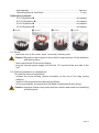
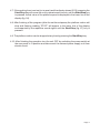
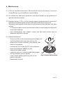
Medical–Biological
Research & Technologies
MSV-3500
Multi Speed Vortex
Operating Manual
Certificate
for version
V.3AW
Contents
1. Safety Precautions
2. General Information
3. Getting Started
4. Operation
5. Specifications
6. Maintenance
7. Warranty and Claims
8. Declaration of Conformity
Page 2
1. Safety Precautions
The following symbol means:
Caution! Make sure you have fully read and understood the present Manual
before using the equipment. Please pay special attention to sections
marked by this symbol.
GENERAL SAFETY
·
Use only as specified in the Operating Manual provided.
·
The unit should be saved from shocks or falling.
·
After transportation or storage keep the unit under room temperature for 2-3hrs
before connecting it to the electric circuit.
·
Use only cleaning and decontamination methods recommended by the
manufacturer.
·
Do not make modifications to the design of the unit.
ELECTRICAL SAFETY
·
Connect only to the external power supply unit with voltage corresponding to that on
the serial number label.
·
Use only the external power supply unit provided with this product.
·
Ensure that the power switch and external power supply are easily accessible
during use.
·
Disconnect the unit from electric circuit before moving.
·
Disconnect the external power supply unit from power socket to turn off the unit.
·
If liquid penetrates into the unit, disconnect it from the external power supply unit
and have it checked by a repair and maintenance technician.
DURING OPERATION
·
Do not impede the platform motion.
·
Do not operate the unit in environments with aggressive or explosive chemical
mixtures.
·
Do not operate the unit if it is faulty or has been installed incorrectly.
Page 3
·
Do not use outside laboratory rooms.
·
Do not place a load exceeding maximum load value mentioned in the Specifications
section of this Manual.
BIOLOGICAL SAFETY
·
It is the user's responsibility to carry out appropriate decontamination if hazardous
material is spilt on or penetrates into the equipment.
2. General Information
MSV-3500 Multi Speed Vortex is designed for soft or intensive mixing of reagents
in different size and type plastic tubes.
It is designed for operation in life-science laboratories working in the fields of
biochemistry, cell and molecular biology.
Unit has four types of interchangeable platforms: for Eppendorf type microtest
tubes, 10/15/50 ml tubes (diameter 12/16/30 mm). Platforms can be ordered
separately or as one set with MSV-3500.
Speed and time are under microprocessor control. LCD display indicates two
lines of values: the set and actual values of speed and time.
Unit provides high maximum speed of platform rotation efficiently mixing
microvolumes (less than 5 ml) of samples.
3. Getting started
3.1. Unpacking.
Remove packing materials carefully and retain them for future shipment or
storage of the unit.
Examine the unit carefully for any damage incurred during transit. The warranty
does not cover in-transit damage.
Caution! Automatic balancing system in this product produces a light metal-like
noise when moving the unit which is likely to be heard during unpacking
and also during operation (acceleration/deceleration of the platform). It
is a normal occurrence and does not indicate a fault or a loose part.
3.2. Complete set. Package contents:
Standard set
MSV-3500 Multi Speed Vortex ............................................................1 piece
external power supply unit...................................................................1 piece
Page 4
spare gasket .....................................................................................2 pieces
Operating Manual, certificate ..............................................................1 copy
Optional accessories
SV-16/8 platform u
.......................................................................on request
SV-10/10 platform v
.....................................................................on request
SV-8/15 platform w
.......................................................................on request
SV-4/30 platform x
.......................................................................on request
3.3. Set up:
place the unit on the clean, even, horizontal, working area;
Caution! Regularly clean support suction feet for improvement of their adhesion
with desk surface.
remove protective film from the display;
plug the external power supply unit into the 12 V socket at the rear side of the
unit.
3.4. Platform installation or replacement.
To install the tube mixing platform:
release the screw turning counter-clockwise on the top of the tube mixing
platform;
install or lift and replace the tube mixing platform;
fix the screw tightly. screwing it with the hand clockwise as far as it will go.
Caution! Improper fixation may cause platform rotation and noise from trembling
at fixation point.
Page 5
4. Operation
Recommendations during operation
Always load the unit evenly. To keep the unit balanced insert EVEN number
of tubes in the opposite sockets on the platform. The opposite tubes must be
filled up equally.
For efficient mixing it is recommended to fill test tubes up to the volume
·
values mentioned in the 5th chapter table 1.
4.1. Connect external power supply unit to a power socket and switch ON (I position)
the power switch located on the rear panel of the unit.
4.2. The unit will turn on and the following readouts will be shown on the display:
previously set time and speed in the upper line (Set);
timer mode indication (STOP/RUN) and current speed in the lower line (Actual).
4.3. Place EVEN number of tubes filled up equally in the opposite sockets on the
platform.
4.4. Use the + and - Speed keys (Fig. 1/7) to set the required speed (increment - 100
rpm). Pressing the key down for more than 2 sec will increase the increment. The
set value is displayed in the upper line of the display (Fig. 1/3).
4.5. Use the + and - Time keys (Fig. 1/5) to set the required working time interval in min
& sec (increment - 1 min). Pressing the key down for more than 2 sec will increase
the increment. The set value is displayed in the upper line of the display (Fig. 1/1).
4.6. Press the Start/Stop key (Fig. 1/6). The platform will start vortexing and the timer
indicator will start counting up the time interval in the lower line of the display Actual (fig.1/2).
3
2
4
1
Min:Sec
Set
Actual
RPM
42:35
STOP
2500
000
Start/Stop
Time
5
Speed
6
fig.1 Control panel
Page 6
7
4.7. If the working time is not set (or is reset) and the display shows 00:00, pressing the
Start/Stop key will cause the unit to operate continuously until the Start/Stop key
is pressed. Actual value of the platform speed is displayed in the lower line of the
display (fig.1/4)
4.8. After finishing of the program (after the set time elapses) the platform motion will
stop and flashing reading ”STOP” will appear in the lower line of the display
accompanied by the repetitive sound signal until the Start/Stop (fig.1/7) key is
pressed.
4.9. The platform motion can be stopped at any time by pressing the Start/Stop key.
4.10. After finishing the operation turn the unit OFF by switching the power switch at
the rear panel to O position and disconnect the external power supply unit from
electric circuit.
Page 7
5. Specifications
The unit is designed for operation in cold rooms, incubators and closed laboratory rooms at
ambient temperature from +4°C to +40°C and maximum relative humidity 80% for temperatures
up to 31°C decreasing linearly to 50% relative humidity at 40°C.
5.1. Speed control range ....................................300–3500 rpm (increment 100 rpm)
maximal speed depends on load see table 2.
5.2. Orbit ...........................................................................................................4 mm
5.3. Digital time setting.................................................................0–60 min / non-stop
5.4. Maximum continuous operation time............................................................8 hrs
5.5. Display ....................................................................................LCD, 2 x 16 signs
5.6. Maximum load ...........................................................................................0.2 kg
5.7. Dimensions ............................................................................180x170x145 mm
5.8. Input current/power consumption .................................................12 V, 1 A / 12 W
5.9. External power supply unit ...... input AC 100–240 V 50/60 Hz, output DC 12 V
5.10. Weight* ...................................................................................................2.6 kg
Table1. Replacement parts and Accessories
Accessories
Capacity
Rated tube
volume, ml
Recommended
volume, ml
Tube
diameter, mm
Catalogue
number
SV-4/30
SV-10/10
4
10
50
10
30
12
BS-010210-AK
BS-010210-BK
SV-16/8
16 / 8 / 8
1.5 / 0.5 / 0.2
11 / 8 / 6
BS-010210-CK
SV-8/15
8
15
20 - 25
5-6
Half of the rated
volume
6-8
16
BS-010210-DK
Platform
Replacement parts
Gasket
BS-010210-S10
Table 2. Max. speed depending on load
Tube loading volume
Platform
25 %
50%
75%
3500
3500
3500
3500
2500
3500
3300
2900
2200
3400**
3300
3000
2700
do not use
RPM
SV-16/8
loaded 0.5 and 0.2 ml tubes
loaded 1.5 ml tubes
loaded 2 ml tubes
all tubes loaded
SV-10/10
SV-8/15
SV-4/30
* Accurate within ±10%.
** Immerse the tubes (2 ml, 75% volume) into the platform SV-16/8 to the level they are filled.
Biosan is committed to a continuous programme of improvement and reserves the right to alter
design and specifications of the equipment without additional notice.
Page 8
6. Maintenance
6.1. If the unit requires maintenance, disconnect the unit from the electric circuit and
contact Biosan or your local Biosan representative.
6.2. All maintenance and repair operations must be performed only by qualified and
specially trained personnel.
6.3. Standard ethanol (75%) or other cleaning agents recommended for cleaning of
laboratory equipment can be used for cleaning and disinfection of the unit.
Regularly clean support suction feet for improvement of their adhesion with desk
surface.
to clean the support suction feet and desk surface use mild soap and water with
a soft cloth or sponge.
wipe excess water from support suction feet and desk surface with an
absorbent soft cloth or sponge.
2
6.4. Gasket replacement
Disconnect the unit from the external power supply unit.
Hold the platform with one hand and turn the
fixing screw counter clockwise to set platform free.
Remove the platform.
4
Unscrew the two screws (fig.2/1) on the distancer
Remove the platform adapter (fig.2/2).
Remove the rubber gasket.
Install the new one, matching inside gasket egde
into the distancer groove (fig.2/4).
Install outside gasket groove (fig.2/3) on the
1
3
fig.2 Gasket replacement
plastic body edge.
Reassemble the unit.
Page 9
7. Warranty and Claims
7.1. The Manufacturer guarantees the compliance of the unit with the requirements of
Specifications, provided the Customer follows the operation, storage and
transportation instructions.
7.2. The warranted service life of the unit from the date of its delivery to the Customer
is 24 months (exclude gasket and platforms mentioned in table 1). Contact your
local distributor to check availability of extended warranty.
7.3. If any manufacturing defects are discovered by the Customer, an unsatisfactory
equipment claim shall be compiled, certified and sent to the local distributor
address. Please visit www.biosan.lv, Technical support section to obtain the claim
form.
7.4. The following information will be required in the event that warranty or postwarranty service comes necessary. Complete the table below and retain for your
records.
Model
Serial number
Date of sale
Page 10
MSV-3500 Multi Speed Vortex
8. Declaration of Conformity
Biosan SIA
Ratsupites 7, build.2, Riga, LV-1067, Latvia
Phone: +371 67426137 Fax: +371 67428101
http://www.biosan.lv
Version 3.02 - October 2013