1
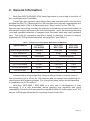
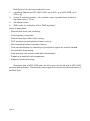
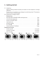
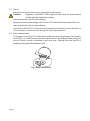
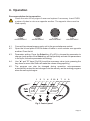
Medical–Biological
Research & Technologies
Centrifuge/vortex
Multi - Spin
MSC-6000 / MSC-3000
Operating Manual
Certificate
for versions:
MSC-3000 - V.2AW
MSC-6000 - V.3AY
Contents
1. Safety Precautions
2. General Information
3. Getting Started
4. Operation
5. Specifications
6. Technical Maintenance
7. Warranty, Reclamation Information
8. Declaration of Conformity
Page 2
1. Safety Precautions
The following symbol means:
Caution!
Make sure you have fully read and understood the present
Manual before using the equipment. Please pay special
attention to sections marked by this symbol.
GENERAL SAFETY
·
Use only as specified in the Operating Manual provided.
The unit should not be used if dropped or damaged.
·
The unit must be stored and transported only in a horizontal position (see
·
marking on the package).
After transportation or storage keep the unit under room temperature for 2-3hrs
·
before connecting it to the electric circuit.
Use only cleaning and decontamination methods recommended by the
·
manufacturer.
Use only original accessories (rotors, pins, etc.) provided by the manufacturer
·
and ordered specifically for this model.
Do not make modifications to the design of the unit.
·
ELECTRICAL SAFETY
Connect only to the external power supply unit with voltage corresponding to that
·
on the serial number label.
Use only the external power supply unit provided with this product.
·
Ensure that the external power supply is easily accessible during use.
·
Do not plug the unit into an ungrounded power socket, and do not use an
·
ungrounded extension lead.
Disconnect the unit from the electric circuit before moving.
·
Disconnect the external power supply unit from power socket to turn off the unit.
·
If liquid penetrates into the unit, disconnect it from the external power supply unit
·
and have it checked by a repair and maintenance technician.
Do not operate the unit in premises where condensation can form. Operating
·
conditions of the unit are defined in the Specifications section.
Page 3
DURING OPERATION
Do not use rotors with visible signs of corrosion, wear or mechanical damage.
·
Do not fill in the tubes after they are inserted in the rotor.
·
Do not operate the unit in environments with aggressive or explosive chemical
·
mixtures. Please contact manufacturer for possible operation of the unit in
specific atmospheres.
Do not use outside laboratory rooms.
·
Do not operate the unit if it is faulty or has been installed incorrectly.
·
For MSC-3000 model: Do not open the lid, touch the rotor or tubes during work,
run-up or run-down of the rotor.
BIOLOGICAL SAFETY
·
It is the user's responsibility to carry out appropriate decontamination if
hazardous material is spilt on or penetrates into the equipment.
Page 4
2. General Information
Multi-Spin MSC-6000/MSC-3000 centrifuge/vortex is a next step of evolution of
the centrifuge/vortex CombiSpin.
Combi-Spin (the previous name Micro-Spin) was invented and for the first time
published by Biol. Dr. V.Bankovskis in 1989 and after the successful approbation and
finishing patented in 1994 (V.K.Bankovskis et al., Riga, Latvia, Pat. No. P94-74).
Spin-mix-spin technology is meant for collection or blowdown on microtube bottom of
microscopic reagent amounts of (the first centrifugation – spin), the following vortexing
(mix) and repeated collection of reagents from microtube walls and caps (repeated
spin). This cycle of successive operations aiming at reduction of errors of sample
preparation for PCR analysis was called „sms algorithm” (see Table 1).
Table 1. Comparison of FVL-2400N, MSC-3000 and MSC-6000
Specifications
Combispin
FVL-2400N
Multi-Spin
MSC-3000
Multi-Spin
MSC-6000
Speed range maximum
2800 rpm
3500 rpm
6000 rpm
RCF maximum
700g
800g
2350g
Number of tubes
1 individually
12 simultaneously
Time for completing “Spin-Mix-Spin” cycle
for 2 microtubes
60 s
25 s
15 s
for 12 microtubes
5-6 min
1 min 30 s
1 min
for 100 microtubes
60 min
15 min
10 min
Unit price ratio
1x
1.6x
1.7x
Implementation of sms algorithm using centrifuge-vortex in manual mode is
time-consuming (up to 60 min for 100 samples) and not exempt from subjectivity on
centrifugation and vortexing stages. For a long time these factors limited speeding
of preparation for PCR reaction.
Multi-Spin MSC-3000 / MSC-6000 is a next step of development of sms
technology: it is a fully automated device realizing sms algorithm with good
repeatability. Productivity of sms algorithm using Multi-Spin is 6 times higher (up to 100
min per 1000 samples) than that for centrifuge-vortex Combi-Spin.
Page 5
Multi-Spin is four devices combined in one:
1.
Centrifuge (Maximum RCF: MSC-3000: up to 800 × g or MSC-6000: up to
2350 × g);
2.
Vortex (3 vortexing modes - soft, medium, hard; regulated time; vortexing
regulation timer 1–20 s);
3.
Centrifuge/vortex;
4.
SMS-cycler for realisation of the “SMS-algorithm”.
Areas of application:
Reproducible multi-tube vortexing;
Centrifugation of samples;
Reproducible Spin->Mix->Spin cycling;
PCR samples premixing before thermo cycling;
Micro sampling before enzymatic reaction;
Cells permeabilization by chelating or hydrophobic agents for reaction in situ;
Low solubility drug testing;
Cells washing from culture media after fermentation;
Preparing a sample for electrophoresis;
Magnetic beads technology.
Automatic stop of MSC-3000 when the lid is open and the lid lock in MSC-6000
provides safe operation. The external power supply unit ensures the electrical safety of
the Multi-Spin.
Page 6
3. Getting started
3.1. Unpacking.
Remove packing materials carefully and retain for future shipment or storage
of the unit.
Examine the unit carefully for any damage incurred during transit. The warranty
does not cover in-transit damage.
3.2. Complete set. Package contents:
Standard set:
Multi-Spin MSC-3000/MSC-6000 centrifuge/vortex . . . . . . . . . . . . . . . . . . 1 pce
external power supply unit . . . . . . . . . . . . . . . . . . . . . . . . . . . . . . . . . . . . . 1 pce
power cord for MSC-6000. . . . . . . . . . . . . . . . . . . . . . . . . . . . . . . . . . . . . . 1 pce
rotor fixation pin . . . . . . . . . . . . . . . . . . . . . . . . . . . . . . . . . . . . . . . . . . . . . 1 pce
R-0.5/0.2 rotor u
. . . . . . . . . . . . . . . . . . . . . . . . . . . . . . . . . . . . . . . . . . . . 1 pce
R-1.5 rotor v
. . . . . . . . . . . . . . . . . . . . . . . . . . . . . . . . . . . . . . . . . . . . . . . 1 pce
Operating Manual; Certificate . . . . . . . . . . . . . . . . . . . . . . . . . . . . . . . . . . 1 copy
Optional accessories:
R-2/0.5 rotor w
. . . . . . . . . . . . . . . . . . . . . . . . . . . . . . . . . . . . . . . . . . on request
R-2/0.5/0.2 rotor x
. . . . . . . . . . . . . . . . . . . . . . . . . . . . . . . . . . . . . . . on request
SR-16 rotor y
. . . . . . . . . . . . . . . . . . . . . . . . . . . . . . . . . . . . . . . . . . . on request
Page 7
3.3. Set up:
place the unit on the clean, even, horizontal, working area;
Caution!
Regularly clean MSC-3000 support suction feet for improvement
of their adhesion with desk surface.
remove protective film from the display;
plug the external power supply unit into the 12 V socket at the rear side of the unit;
remove protective film from the display;
according to EN 61010-2-20 people and hazardous materials must not be within a
300 mm area around the device during the centrifuge operation.
3.4. Rotor replacement:
To change a rotor (Fig.1/2): insert the provided pin into the opening in the fixation
head (Fig.1/1). Hold the rotor with one hand and turn the fixation head (using the
pin as a lever) counter clockwise to set rotor free. Change the rotor and fix it
properly putting back the fixation head.
Fig.1 Rotor replacement
Page 8
4. Operation
Recommendation during operation
Check the rotor for any signs of wear and replace if necessary. Insert EVEN
number of tubes in rotor one opposite another. The opposite tubes must be
filled equally.
2 TUBE
ARRANGEMENT
4 TUBE
ARRANGEMENT
6 TUBE
ARRANGEMENT
FULL
ARRANGEMENT
4.1.
Connect the external power supply unit to the grounded power socket.
4.2.
Open the lid and place EVEN number of tubes in rotor sockets one opposite
another. Close the lid.
4.3.
Parameter setting: Press the Select key (Fig.2/3) to choose the parameter to
change (each press of the Select key will sequentially activate the parameters
in the cycle, the active parameter is blinking).
4.4.
Use “▲” and “▼“ keys (Fig.2/6) to set the necessary value (note: pressing the
key down for more than 2 sec will make the values change quickly).
4.5.
The program can also be changed during operation: microprocessor
automatically enters the last changes into the memory as the working program
when the new cycle begins.
1
3000
0:00
2
3
HARD
OFF
4
5 10 6
7
8
9
OFF
STOP
Fig.2 Control panel
Page 9
4.6.
SMS - algorithm
4.6.1. Set the required spinning speed (increment 100 rpm, Fig.2/1).
4.6.2. Set centrifugation time (time less than 1 min - with 1 s increment, more than
1 min - with 1 min increment, Fig.2/2).
4.6.3. Set the vortexing intensity (select from soft, medium and hard, Fig.2/4).
4.6.4. Set the time of vortexing, from 1 to 20 s (increment 1 sec, Fig.2/5).
4.6.5. Set the number of the set sms-algorithm repetitions (from 1 till 999 times,
Fig.2/7).
4.7.
Centrifugation
4.7.1. Set the necessary speed of spin (increment 100 RPM, Fig.2/1).
4.7.2. Set the centrifugation time (time less than 1 min - with 1 s incrment, more than
1 min - with 1 min increment, Fig.2/2).
4.7.3. Turn off the Vortex type motion by setting the time of Vortex type motion to zero
(OFF, Fig. 2/5). Note that the cycle counter turns off.
4.8.
Vortexing
4.8.1. Turn off the Spin motion by setting the time of Spin motion to zero (OFF, Fig.
2/2). Note that the cycle counter turns off.
4.8.3. Set the vortexing intensity (select from soft, medium and hard, Fig.2/4).
4.8.4. Set the time of vortexing (from 1 till 20 sec, increment 1 sec, Fig.2/5).
4.9.
Press the Run/Stop key (Fig.2/9) to start the program.
4.10. The rotor motion will begin and the corresponding indication (RUN (Fig.2/8),
cycle countdown (Fig.2/7), the changing time values (Fig.2/2 or Fig.2/5)) and
for MSC-6000 lid lock symbol (fig.2/10) will be shown on the display.
4.11. Multi-Spin automatically stops after the set number of cycles is performed
(blinking indication STOP (fig.2/8) on the display) and gives a sound signal
about the end of operation (press the Run\Stop key to stop the signal).
4.12. For the repeated operation according to the set program press the Run\Stop
key.
4.13. If necessary Multi-Spin can be stopped at any time during operation before the
set number of cycles is performed by pressing the Run/Stop key. Pressing the
Run/Stop key again will start the program from the beginning (cycle countdown
will be restarted).
4.14. After finishing the operation unplug the external power supply unit form electric
circuit to turn off the device.
Page 10
Note!
The MSC-6000 electromechanical lid lock allows opening the lid
only when the centrifuge is connected to the power supply and is
turned on. Do not force the lid to open when the centrifuge is
switched off!
4.15. MSC-6000 lid emergency opening
4.15.1.Disconnect the external power supply unit from electric circuit and wait until the
centrifuge rotor stops.
4.15.2.Move the centrifuge to the front of the bench to access the emergency opening
slot on the underside of the unit (located under the front side left feet). Avoid
tilting the centrifuge as this may cause spilling of the materials from the
containers inside the centrifuge.
4.15.3.Insert a small screwdriver, or a similar tool (with diameter up to 3 mm) into the
emergency opening slot at 15 mm depth and move the lever from the left to the
right side with one hand and simultaneously with another hand open the lid.
Page 11
5. Specifications
The unit is designed for operation in cold rooms, incubators and closed laboratory
rooms at ambient temperature from +4°C to +40°C in a non-condensing atmosphere
and maximum relative humidity 80% for temperatures up to 31°C decreasing linearly to
50% relative humidity at 40°C.
Model
MSC-3000
MSC-6000
Speed control range
(increment 100 rpm)
1000 - 3500 rpm
1000 - 6000 rpm
Maximum RCF
800g
2350g
Spin timer
1 s - 99 min
1 s - 30 min
Vortexing intensity
Soft, medium, hard
Vortexing time
0 - 20 s (increment 1s)
SMS-cycle regulation
Safety
1 - 999 cycles
Autostop at open lid
Lid lock
Weight*
2.1 kg
2.5 kg
Input current / power
consumption
DC 12V / 11 W (0.9 A)
DC 24V / 24 W (1 A)
External power supply
input AC 100-240 V 50/60Hz
output DC 12V
output DC 24V
* Accurate within ±10%.
Optional accessories
Description
Catalogue number
R-2/0.5 rotor
for 8x2.0 ml and 8x0.5 ml
microtest tubes
BS-010205-CK
R-2/0.5/0.2 rotor
for 6x2.0 ml, 6x0.5 ml and 6x0.2 ml
microtest tubes
BS-010205-DK
SR-16 rotor
for 2 strips for 8x0.2 ml microtest tubes
BS-010202-AK
Replacement parts
Description
Catalogue number
R-1.5 rotor
for 12x1.5 ml microtest tubes
BS-010205-AK
R-0.5/0.2 rotor
for 12x1.5 ml and 12x0.2 ml
microtest tubes
BS-010205-BK
Biosan is committed to a continuous programme of improvement and reserves
the right to alter design and specifications of the equipment without additional notice.
Page 12
6. Maintenance
6.1. If the unit requires maintenance, disconnect the unit from the electric circuit
and contact Biosan or your local Biosan representative.
6.2. All maintenance and repair operations must be performed only by qualified and
specially trained personnel.
6.3. Standard ethanol (75%) or other cleaning agents recommended for cleaning of
laboratory equipment can be used for cleaning and disinfection of the unit.
Regularly clean MSC-3000 support suction feet for improvement of their
adhesion with desk surface.
To clean the support suction feet and desk surface, use mild soap and water with a
soft cloth or sponge. Wipe excess water from support suction feet and desk
surface with an absorbent soft cloth or sponge.
Page 13
7. Warranty and Claims
7.1. The Manufacturer guarantees the compliance of the unit with the requirements of
Specifications, provided the Customer follows the operation, storage and
transportation instructions.
7.2. The warranted service life of the unit from the date of its delivery to the Customer
is 24 months. Contact your local distributor to check availability of extended
warranty.
7.3. If any manufacturing defects are discovered by the Customer, an unsatisfactory
equipment claim shall be compiled, certified and sent to the local distributor
address. Please visit www.biosan.lv, Technical support section to obtain the claim
form.
7.4. The following information will be required in the event that warranty or postwarranty service comes necessary. Complete the table below and retain for your
records.
Model
Serial number
Date of sale
Page 14
Multi-Spin MSC-3000 / MSC-6000 Centrifuge / Vortex
8. Declaration of Conformity
Page 15
Biosan SIA
Ratsupites 7, build.2, Riga, LV-1067, Latvia
Phone: +371 67426137 Fax: +371 67428101
http://www.biosan.lv
Version 2-3.03 – January 2014