1
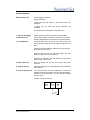
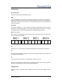
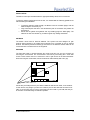
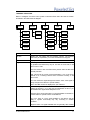
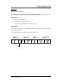
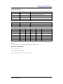
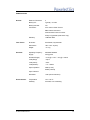
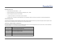
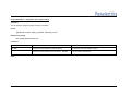
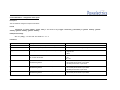
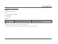
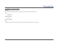
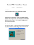
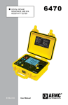
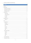
IN4MA Metron D
GSM/GPRS Telemetry Solution
Technical Manual and Specification
Revision 0.2.1
17th April 2008
© 2007 Powelectrics Ltd.
1
Powelectrics Ltd
Sandy Hill Park
Sandy Way
Tamworth
Staffordshire
B77 4DU
United Kingdom
Tel: +44 (0)1827 310 666
Fax: +44 (0) 1827 310 999
www.powelectrics.co.uk
[email protected]
Proprietary Notice:
The information in this document is subject to change without notice. Company or product names
mentioned in this document may be trademarks or registered trademarks of their respective
companies.
All rights reserved. Neither the whole nor any part of the information contained in this publication
may be reproduced in any material form except with the written permission of Powelectrics Ltd.
This publication is intended only to assist the reader in the use of the product. Powelectrics Ltd.
shall not be liable for any loss or damage arising from the use of any information in this publication,
or any error or omission in such information, or any incorrect use of the product.
© 2007 Powelectrics Ltd.
2
DOCUMENT HISTORY
Version
Date
0.1
12/09/07
First release
0.2
24/09/07
Second Release, inc remote programming guide
0.2.1
17/04/08
Corrected oli.3. programming format – settle -> 1 (was 0)
© 2007 Powelectrics Ltd.
Comments
3
Technical Manual and Specification ...................................................................... 1
WARNINGS ......................................................................................................................................... 5
OVERVIEW.......................................................................................................................................... 6
NAVIGATION BASICS ........................................................................................................................ 6
GETTING STARTED ........................................................................................................................... 7
CONNECTIONS................................................................................................................................... 9
THE MENU STRUCTURE ................................................................................................................. 11
CONFIGURATION ............................................................................................................................. 13
© 2007 Powelectrics Ltd.
4
WARNINGS
Safety
Read carefully these instructions and notes before powering IN4MA Metron. For each
situation please follow the specific instructions.
The Metron is a low power radio transmitter and receiver. When it is powered, it will send and
receive radio frequency (RF) signals.
Operating the Metron close to other electrical equipment such as television, phone, radios
and personal computer, may cause interference.
Interference
The Metron, like all wireless devices, is subject to interferences that may reduce its
performance.
Road Safety
Do not use the Metron while driving. In case of use on cars, it is necessary to check that
electronic equipment is shielded against RF signal. Do not place the Metron over the air bag
or in the air bag deployment area.
Hospital Safety
Do not use the Metron near health equipment, especially pacemaker and hearing aids, to
avoid potential interferences. The Metron is a not mobile phone; do not use it in direct contact
with the human body. Switch it off in hospitals, and in any other type of medical centre.
Hospitals or health care facilities may be using equipment that could be sensitive to external
RF energy.
Explosive Materials
Do not use the Metron in refueling points, near fuel or chemicals. Do not use the Metron
where blasting is in progress. Observe restrictions, and follow any regulation or instruction.
Do not use the Metron in direct contact with the human body; do not touch the antenna if not
necessary when the Metron is powered. Use approved accessories and batteries only. Do not
connect incompatible products.
Included Battery
Do not use if the battery casing appears damaged
Do not attempt to recharge the battery
Do not short circuit
Only use supplied battery with the IN4MA Metron
Replacing the Battery
The battery used in the Metron must be supplied by Powelectrics Ltd. Its warranty will be void
if any other battery is used as it may damage the Metron or cause it to malfunction.
To remove the battery, simply remove the plug from the PWR socket – Do not pull on the
connecting wires. The battery can now be easily pulled from the retaining clip. Push the new
battery into the retaining clip centrally, and then reconnect the plug to the socket on the
Metron board.
© 2007 Powelectrics Ltd.
5
OVERVIEW
This document describes all the functions, features and interfaces of the IN4MA Metron
telemetry device.
Applications
A few of the applications that this device has been designed for include:
Meter Reading
Condition Monitoring
Alarm Reporting
Summary of Technical Features
Ability to interface with up to four 0-10V digital inputs
On-board wetting voltage
Typically > 5 year battery life
LCD Display to help with on-site setup
Tri-band operation
As the Metron is a battery powered device it has been designed in such a way to extend this
life to a maximum. This means during normal operation the display will be off, the sensors
excitation will be off and the GSM engine will be powered down. As required these are
switched on by the processor and when finished with they are switched off.
GENERAL DECRIPTION OF OPERATION
NAVIGATION BASICS
A common method is used throughout the menu system for navigation.
To move up within a menu – You must use the top button to the left of the screen (UP) to
move up if you are navigating in a menu.
To move down within a menu – You must use the bottom button to the left of the screen
(DOWN) to move down if you are navigating within a menu.
To select an item on a menu – You must press the central button to the left of the screen
(ENTER) for less than one second to select an item if you are within a menu.
To go to the previous menu – You must press the central button to the left of the screen for
more than one second to return to the previous menu. You should continue to hold until the
previous menu appears.
To return to the previous menu when displaying information – If the Metron is just
displaying information, you can return to the previous menu by simply pressing the central
button to the left of the screen briefly.
© 2007 Powelectrics Ltd.
6
GETTING STARTED
What you will need:
A large Phillips screwdriver
A 3mm Allen driver
A SIM card with the ability to send and receive text
messages
A device that can send and receive specified text
messages
The latest version of the Metron configuration tool
1. Open the packaging
Cut the seals from the box and open the cardboard lid
2. Remove the lid
Using a large Phillips screwdriver, remove the four screws
fastening the plastic lid to the enclosure and remove the lid
3. Fit the SIM card
Using the Allen driver, remove the four outer screws from
the circuit board and tilt the circuit board 90 degrees to the
right
Carefully remove the antenna cable from the circuit board –
do not use excessive force.
Slide the SIM card into the SIM card holder. The final
position is drawn onto the circuit board.
Re-attach the antenna cable and fasten the circuit board
using the four outer screws.
4. Power up the unit
Place the battery into the clip and connect the power
connector.
5. Program the unit
Follow the instructions for configuration that are stated later
in this manual.
6. Connect inputs & test
For each input that you have programmed, connect the
required sensor and navigate to the relevant input settings.
Choose the ‘Read Now’ option to see a real time reading
from the sensor.
Volt free contact connections
© 2007 Powelectrics Ltd.
7
0-10 Volt DC input from external source
7. Put the Metron to sleep Return to the main menu then press and hold the central
button until it displays ‘Sleeping..’. The Metron will now be
operational.
© 2007 Powelectrics Ltd.
8
CONNECTIONS
Serial Debug Port
This port is for internal use at Powelectrics only.
PWR
This socket should only be used for connecting the battery to the board. It is polarised – It
should be impossible to connect the power incorrectly. Ensure that a secure connection is
made. When you remove the connector, do not pull using the wires as this may impair the
electrical connection.
DIL Switch
Each of the 4 (labelled 1, 2, 3 and 4) switches in this bank should always be set to 0-10V for
the Metron-D. The bottom position is 0-10V, while the top position is 4-20mA. If the input is
not enabled, it does not matter which position the corresponding switch is set to.
INPUT 1, 2, 3 and 4
Each sensor or connected input has its own plug and corresponding socket. On each socket,
three connections are available.
0V
This is the 0V / -Ve connection for the channel, although they are all common to each other.
+V
This will provide the wetting voltage to the channel. It is important that the load on this does
not exceed the specifications.
IN
This is the input for the channel – This will accept any input from 0-10V.
Note: It is important that the channel used for the sensor excitation and the sensor inputs are
the same. The connection to ground is not channel dependant.
PUSHBUTTONS
These are used in conjunction with the display in order to access and navigate the menu
system.
© 2007 Powelectrics Ltd.
9
INSTALLATION
The Metron comes pre-assembled with the appropriate battery fitted, but not connected.
To achieve optimum performance from the unit, it is advised that the following guidelines are
followed during the installation:
•
•
•
To achieve optimum signal strength, the Metron must be mounted upright, with the
label reading the correct way up
Large metal objects that are in the transmission path of the Metron may hinder the
performance
Check that the glands are tightened and any blanking plugs are fitted tightly. The
inside of the unit must remain dry, as water ingress may damage the Metron.
ANTENNA
The Metron comes with an antenna attached. The system has been designed to gain
optimum signal strength to the mobile phone network but it is possible to use an external
antenna. The Metron presents an SMA type connector for the antenna and the cable can be
connected into the enclosure via one of the glands.
SIM CARD
The SIM card holder is located beneath the circuit board and can only be accessed by
removing the circuit board. The circuit board is removed by unscrewing the 4 outer Alan
screws. These screws need to be removed in order to gain access to the SIM card holder.
When removing the circuit board, remove the antenna cable carefully with a firm grip.
Check with your GSM provider if your SIM is enabled for data and fax traffic, if not ask them
for this service, they will give you other two numbers (one for data calls and the other for fax
calls). If you are using ‘pay as you go’ ensure that you have credit on your SIM, and that you
do not have a minimum usage to maintain operation.
© 2007 Powelectrics Ltd.
10
THE MENU STRUCTURE
Below is a diagram of how the menu system is structured. Each menu item has its function
described in the table below the diagram.
Menu Item
Function
Unit Info
Displays the Unit Name and the Firmware Version. The firmware
version may be requested if you contact Powelectrics for support.
Intervals
Displays the transmit interval.
Diagnose
A self diagnostic function that allows the user to determine if there are
any problems and where they may lie. For each of the checks, it will
return ‘Pass’ or ‘Fail’.
SIM: This checks to see if the SIM card is present and if the SIM card
has PIN protection.
REG: This checks for correct network registration. If it is on the home
network or on a roaming network and is connected correctly, it will
return ‘Pass’.
SIG: This checks the signal strength and returns ‘Pass’ if the signal is
strong enough for the Metron to operate reliably.
IMEI #: The IMEI number is displayed for your reference.
Check Signal
This feature logs onto the network and monitors the signal strength. It
displays the signal (0 – 31 or 99) and an interpretation of this so you
can evaluate if the signal will be adequate or not.
No Signal: There is extremely little or no signal available to the Metron.
It will be unable to operate in these circumstances.
Very Poor: There is a poor signal available to the Metron and the
ability to operate successfully may vary according to weather
conditions.
Marginal: There is a signal available that can generally allow reliable
© 2007 Powelectrics Ltd.
11
operation of the Metron.
Signal OK: The signal is well above operational levels.
Excellent: The signal is very good – optimum conditions for successful
Metron operation.
Note: If you do not have a SIM card present in the Metron, this function
will still operate but instead will read the signal strength of the
strongest operator signal present.
Get Config
To configure the Metron via text message, you must first put the
Metron into configuration mode. By selecting ‘Get Config’, it will do this
and interpret any text messages that are received.
View Numbers
When selecting ‘View Numbers’, it will display the four numbers that
are present in the Metron phonebook. If a number has not been
programmed, it will show ‘No Number’ by the corresponding entry.
Edit Numbers
When selecting ‘Edit Numbers’, it will present each of the four phone
number spaces in turn in a way that allows you to edit them. Use the
up and down keys to change the numbers in turn. The character ‘>’ will
terminate character entry.
Input 1, 2, 3, 4
When selecting any of the inputs, it will bring up a sub-menu that
directly corresponds to the input that has been selected.
Disable/Enable
By choosing this option, it will enable or disable the input alternately. A
confirmation message will follow.
Input Name
This will display the name that has been given to the input. This name
can be edited by using the up and down keys to change the characters
in turn. The character ‘>’ will terminate character entry. It will also
confirm that the input is enabled.
SMS To..
This displays which phone numbers will be sent a text message when
the corresponding input is triggered. Each can be edited by using the
up and down keys to change between ‘yes’ and ‘no’. Pressing the
enter key will confirm the selection and move to the next phone
number entry.
Threshold
The threshold menu displays the point at which an alarm will be
triggered. This threshold is set in Volts. Use the up and down keys to
change the value, pressing enter to confirm your selection.
The alarm can be triggered on:
- Going from above the threshold to below the threshold (high to low)
- Going from below the threshold to above the threshold (low to high)
- Both of the above
Using the up and down keys will change between these options.
Pressing the enter key will confirm the selection.
Read Now
This allows real time monitoring in an oscilloscope style format – The
scaled value (in Volts) is displayed in the upper left hand corner,
followed by the state (High or Low) in brackets. This can be useful for
resolving and testing input issues.
Temp
This will display the temperature of the current environment.
Test
This displays the voltage and state of each input
© 2007 Powelectrics Ltd.
12
CONFIGURATION
The Metron D can be configured in one of two ways:
Locally, using the LCD screen and buttons
Remotely, by sending commands to the Metron via text message
Each of these methods is described individually. It is recommended that the local
programming procedure is followed for initial setup.
LOCAL PROGRAMMING
The Metron D has the following configurable options:
Node name – This is the unique identifier that identified the Metron D. This name is
used at the top of each text message sent.
Transmit Interval – This is the length of time (in minutes) between each log
transmission. This transmission contains the state of each input.
Phone numbers 1, 2, 3, 4 – These are the phone numbers that the Metron D is
capable of sending a text message to
For each input:
Enable / Disable input
Input Name – used to identify the input
A choice of which phone book entries to text message
Trigger threshold
Trigger condition
Step #1 – System Settings
The System settings consist of the Node name and transmit interval.
Firstly, select ‘System’ from the main menu, then choose ‘Unit Info’. You will be prompted with
the Node name and the firmware version. Using the up and down keys select the desired
character, then press enter to confirm and move to the next character. Repeat this process
until you have entered the desired Node name. Select the ‘>’ character to terminate the Node
name.
The transmit interval can be altered by selecting ‘System’ from the main menu, then choosing
‘Transmit Interval’. Using the up and down keys, increase or decrease the desired transmit
interval. Press the enter key to confirm the transmit interval.
Step #2 – Programming the phone book
The phone book contains the numbers that the Metron D is capable of text messaging. Each
of these numbers must be entered in full, including the country code e.g. +441234567890.
To program the phone book select ‘Phonebook’ from the main menu followed by selecting the
‘Edit Numbers’ option. It will default to editing the first phone number entry, with the first
character shown being either ‘+’ or the ‘No number’ option. Using the up and down keys,
© 2007 Powelectrics Ltd.
13
change each digit in turn followed by the enter key to confirm your selection. Select the ‘>’
character to terminate each phone number.
Step #3 – Configuring the inputs
For each input, the same series of configurable options are available: Input name, which
phone book entries to text message, trigger threshold and trigger condition.
Firstly, you must select the input that you wish to configure. Select ‘Inputs’ from the main
menu followed by the input number that you wish to select.
To enable the input, select the ‘enable’ option from the menu. Confirmation of the enabled
input will then be displayed.
To rename the input, select ‘Input Name’ from the menu. Using the up and down keys,
change each character in turn followed by the enter key to confirm your selection. Select the
‘>’ character to terminate the name.
To change which phone numbers will be sent a text message when the corresponding input is
triggered, select ‘SMS to..’ from the menu. Each can be edited by using the up and down keys
to change between ‘yes’ and ‘no’. Pressing the enter key will confirm the selection and move
to the next phone number entry.
To change the threshold and trigger state, select ‘Threshold’ from the menu. To adjust the
trigger threshold displayed, use the up and down keys to set the threshold followed by the
enter key to confirm the selection. To adjust the trigger state, use the up and down keys to
select the mode you wish, followed by the enter key to confirm the selection.
Step #4 – Testing the Inputs
For each input, it is advisable to test the sensor prior to placing the Metron D into the sleeping
state. To test, go to ‘Inputs’ from the main menu followed by the appropriate input you would
like to test. Then select the ‘read now’ option.
A live graph will be displayed of the corresponding input. Above this graph is the current
voltage and the state (dependant on threshold).
Step #5 – Placing the Metron D into run mode
The Metron D ‘runs’ when it is placed into a sleeping state. To achieve this, press and hold
the enter key until ‘Sleeping..’ is displayed on the screen. The inputs are then continually
monitored for change. Upon a threshold being crossed, the Metron D will power up and send
a text message to the appropriate phone book entries.
REMOTE PROGRAMMING
The Metron D can be remotely programmed by sending commands via text message. Each of
these commands must be sent separately. The formatting of each command is described in
detail in the section Programming Specification.
To receive the commands, Press the (ENTER) button to ‘wake up’ the Metron, go to ‘System’
and then go to ‘Get Config’. The display should read ‘Waiting for Messages..’ after it has
© 2007 Powelectrics Ltd.
14
established You must wait until each of the text messages sent has been received and
successfully interpreted – It will display ‘Success’ or ‘Invalid Command’ in each case.
When all the messages have been received, press and hold the central button until you are
returned to the main menu. If you leave the unit unattended for several minutes it will go into
sleep mode.
© 2007 Powelectrics Ltd.
15
Example #1
Real Time Security Monitoring
A PIR sensor has a volt free contact available – When the PIR senses movement, the metron
must immediately pick up the contact and send an alarming message.
Requirements:
Must alarm to one number
It should send a regular log once a day
It must check the signal more than 4 times a second
Configuration:
We will use +447771111111 in our example. +447771111111 will be used to receive any
alarms that are triggered.
The contact is wired to input one as shown in the diagram below
© 2007 Powelectrics Ltd.
16
Example #1 Settings
Entry
Value
Notes
Phone Number 1
+447771111111
Phone Number 1 is always the number that will be
transmitted to upon a transmit interval.
Phone Number 2
Leave blank
Phone Number 3
Leave blank
Phone Number 4
Leave blank
Entry
Value
Unit Name
house_alarm
Transmit Interval
1440
Parameter
Input 1
Input Name
PIR_1
Trigger condition
0
Threshold
15
Phone Number 1
Yes
Phone Number 2
No
Phone Number 3
No
Phone Number 4
No
Notes
0 = Do not transmit upon interval
Input 2
Input 3
Input 4
Notes
Notes:
The threshold is set at 15, so it will be triggered when input one rises above 1.5V
Generated Text Messages
oli.1.+447771111111.
oli.2.house_alarm.1440.0.0.0.
oli.3.1.PIR_1.0.0.0.0.101.0.0.0.15.0.1.0.0.0.
© 2007 Powelectrics Ltd.
17
SPECIFICATION
General:
Number of Channels:
4
Battery Life:
Typically > 5 Years
Battery Included:
Yes
Connectors:
3 Pin 3.81mm Pitch / Sensor
SMA Antenna Connector
2.54mm Molex Power Connector
9 Way D-Type Male (internal use only)
Form Factor:
Electrical:
Warranty:
12 Months RTB
Enclosure:
IP67 Rated, Polycarbonate
Dimensions:
180 x 130 x 76 (mm)
Weight:
~ 0.7 Kg
Operating Frequency:
900/1800/1900Mhz
Supply:
3.6V @ 0.5A
Excitation Supply:
~ 3.6V @ < 0.5A / ~ 21V @ < 120mA
Load (Sleep):
~ 50µA
Load (Active):
~ 6mA
Load (Modem):
~ 12 – 250mA
Input Impedance:
33KΩ (0-10V)
XXXΩ (4-20mA)
Input Tolerance:
Environmental:
Resolution:
10 bit (1024 Increments)
Temperature:
-15 to +45 ºC
Humidity:
20 to 80% non-condensing
© 2007 Powelectrics Ltd.
18
IN4MA Metron D
GSM/GPRS Telemetry Solution
Programming Specification
12th September 2007
© 2007 Powelectrics Ltd.
19
Powelectrics Ltd
Sandy Hill Park
Sandy Way
Tamworth
Staffordshire
B77 4DU
United Kingdom
Tel: +44 (0)1827 310 666
Fax: +44 (0) 1827 310 999
www.powelectrics.co.uk
[email protected]
Proprietary Notice:
The information in this document is subject to change without notice. Company or product names mentioned in this document may be trademarks or registered
trademarks of their respective companies.
All rights reserved. Neither the whole nor any part of the information contained in this publication may be reproduced in any material form except with the written
permission of Powelectrics Ltd.
This publication is intended only to assist the reader in the use of the product. Powelectrics Ltd. shall not be liable for any loss or damage arising from the use of any
information in this publication, or any error or omission in such information, or any incorrect use of the product.
© 2007 Powelectrics Ltd.
20
Important points to note
Valid characters are 0-9, a-z, A-Z, +, -, _ and .
Spaces are allowed but not recommended (they are ambiguous), use _ instead
All text messages and names are case insensitive.
. is used as the separator, and is also used to end the command.
The Metron does not use phone number identification as an authorisation method. The security for the Metron is a single three digit password.
The text message format
The format of a text message to program the Metron is shown below. [ and ] are not literal characters, they enclose a description of what is expected. There
may be more than one parameter, but this is dependant on the command being issued.
[password].[command number].[parameters].
Every text message sent to the Metron will only be processed if it begins with the correct three digit password. If this is not the case, no action will be taken.
The default password is ‘oli’. The command numbers are as followed.
Command Number
Description
1
This is used to program the phone book
2
This is used to configure the system settings
3
This is used to configure the inputs
4
This is used to change the password
5
This is used to reset the system to factory settings
6
This is used to request the configuration and status
© 2007 Powelectrics Ltd.
21
Command Number 1 – Programming the phone book
Description
This command will set up to four of the phone book entries on the Metron.
Format
[password].1.[phonenumber1].[phonenumber2].[phonenumber3].[phonenumber4].
Example text message
oli.1.+447712345671.+447712345672.+447712345673.+447712345674.
Parameters
Parameter
Description
Limitations
Phone number
The phone number of a device to transmit to
The phone numbers can be up to 13 digits in length, including ‘+’
Notes
You must include the country code e.g. +44.
If you need to set fewer than four phone book entries, use the same format but omit the desired numbers. For example:
oli.1.+447712345671.+447712345672.
The numbers are programmed into the phonebook in order
© 2007 Powelectrics Ltd.
22
Command Number 2 – Configuration of the system settings
Description
This command will configure the system settings on the Metron.
Format
[password].2.[unit name].[transmit interval].0.0.0.
Example text message
oli.2.pump_house.1440.0.0.0.
Parameters
Parameter
Description
Limitations
Unit name
A unique name that identifies the particular Metron
This cannot be more than 20 digits in length
Transmit Interval
How frequently the unit will wake up and transmit readings from This must be between 0 and 65536 Minutes
the sensors. This will transmit to phone number 1. (Minutes)
0 = Do not wake up and send log
Notes
© 2007 Powelectrics Ltd.
23
Command Number 3 – Configuration of the Inputs
Description
This command will configure the inputs on the Metron
Format
[password].3.[input number].[input name].1.0.0.0.101.0.0.[trigger condition].[threshold].0.[phone1 enable].[phone2
enable].[phone3 enable].[phone4 enable].
Example text message
oli.3.1.pump_1.1.0.0.0.101.0.0.0.50.0.1.1.1.1.
Parameters
Parameter
Description
Limitations
Input number
The number of the input that you want to configure
Must be 1, 2, 3 or 4
Input name
A name to identify the input
This cannot be more than 20 digits in length
Trigger Condition
This configures the conditions upon which the input is triggered 0 = Low to High
1 = High to Low
2 = Both
Threshold
This is the alarm threshold. When the sensor value rises above Must be between 0 and 100.
this, an alarm will be sent
0 = 0V
100 = 10V
Phone1 enable
If phone number 1 should be alarmed to upon an alarm
threshold being broken.
Boolean – Must be 1 (enabled) or 0 (disabled)
0 = Do not text phone number 1 upon alarm
1 = Do text phone number 1 upon alarm
Phone2 enable
If phone number 2 should be alarmed to upon an alarm
threshold being broken.
Boolean – Must be 1 (enabled) or 0 (disabled)
0 = Do not text phone number 2 upon alarm
1 = Do text phone number 2 upon alarm
Phone3 enable
If phone number 3 should be alarmed to upon an alarm
threshold being broken.
Boolean – Must be 1 (enabled) or 0 (disabled)
0 = Do not text phone number 3 upon alarm
© 2007 Powelectrics Ltd.
24
1 = Do text phone number 3 upon alarm
Phone4 enable
If phone number 4 should be alarmed to upon an alarm
threshold being broken.
Boolean – Must be 1 (enabled) or 0 (disabled)
0 = Do not text phone number 4 upon alarm
1 = Do text phone number 4 upon alarm
Notes
You will need to send a single instance of this command for each input you would like to program (specifying the input number)
© 2007 Powelectrics Ltd.
25
Command Number 4 – Changing the password
Description
This command will change the password
Format
[password].4.[new password].
Example text message
oli.4.pow.
Parameters
Parameter
Description
Limitations
New password
This is the password that will replace the current password
It cannot be more than 3 digits in length
Notes
Once you have set this password, the new password will come into effect immediately
Powelectrics can remotely reset your Metron if you have forgotten the password. Contact Powelectrics for more information.
© 2007 Powelectrics Ltd.
26
Command Number 5 – Clearing the configuration
Description
This command will reset all settings on the Metron, including the system password (returns to the default password)
Format
[password].5.
Example text message
oli.5.
There are no parameters
Notes
Powelectrics can remotely reset your Metron if you have forgotten the password. Contact Powelectrics for more information.
© 2007 Powelectrics Ltd.
27
Command Number 6 – Requesting Configuration and Status
Description
This command will prompt the Metron upon the next Transmit Interval to send the current configuration and status to the device that has sent the command using SMS
messaging
Format
[password].6.
Example text message
oli.6.
There are no parameters
Notes
It will only respond when the Metron reaches its next Transmit Interval
It will send the SMS message only to the device that sent the command.
© 2007 Powelectrics Ltd.
28
IN4MA Metron D
GSM/GPRS Telemetry Solution
Alarm Format Specification
28th July 2006
© 2007 Powelectrics Ltd.
29
Powelectrics Ltd
Sandy Hill Park
Sandy Way
Tamworth
Staffordshire
B77 4DU
United Kingdom
Tel: +44 (0)1827 310 666
Fax: +44 (0) 1827 310 999
www.powelectrics.co.uk
[email protected]
Proprietary Notice:
The information in this document is subject to change without notice. Company or product names mentioned in this document may be trademarks or registered
trademarks of their respective companies.
All rights reserved. Neither the whole nor any part of the information contained in this publication may be reproduced in any material form except with the written
permission of Powelectrics Ltd.
This publication is intended only to assist the reader in the use of the product. Powelectrics Ltd. shall not be liable for any loss or damage arising from the use of any
information in this publication, or any error or omission in such information, or any incorrect use of the product.
© 2007 Powelectrics Ltd.
30
Important points to note
The Metron does not use phone number identification as an authorisation method. The security for the Metron is a single three digit password.
All scaled values are rounded to the nearest whole number.
When the Metron will send a text message
There are four possible triggers that can cause the Metron to send a text message. These are:
A Periodic Log – Every time the transmit interval has elapsed, the Metron will transmit the readings from all of the sensors that are enabled
An Alarm – Every time the wake up interval has elapsed and a reading passes a threshold requirement the reading in question will be transmitted
A Status Request – Upon logging onto the phone network and the reception of command 6, it will transmit the status of all inputs and settings
Reset Confirmation – When the unit has been remotely reset, a confirmation will be sent to the number issuing the command
Each has its own text messaging format, explained on the following pages
How the formats are described.
[ and ] are not literal characters, they enclose a description of what will be sent, for example:
[state]
© 2007 Powelectrics Ltd.
31
Periodic Log text message format
Description
Every time the transmit interval is elapsed, the Metron will transmit the readings from all of the sensors that are enabled. If a particular input is not enabled,
the name and reading of the input will simply be omitted.
Formatting Modes
The formatting of a Periodic Log text message is dependant on the formatting mode in the system settings. It is not possible to operate the Metron in a
combination of the formatting styles.
‘User’ Formatting
LOG: [unit name]
[input 1 name]: [input
[input 2 name]: [input
[input 3 name]: [input
[input 4 name]: [input
[temperature] C
state]
state]
state]
state]
‘User’ Example
LOG: pump_house
pump_1: HIGH
pump_2: LOW
pump_3: LOW
pump_4: LOW
22.125 C
© 2007 Powelectrics Ltd.
32
On Alarm text message format
Description
When a reading from an input is taken at a wakeup interval and it has passed below a threshold that has been set for that input, an alarm will be raised.
Formatting
Formatting
ALARM: [unit name]
[input 1 name]: [input
[input 2 name]: [input
[input 3 name]: [input
[input 4 name]: [input
[temperature] C
state]
state]
state]
state]
Example
ALARM: pump_house
pump_1: HIGH
pump_2: LOW
pump_3: LOW
pump_4: LOW
22.125 C
Notes
© 2007 Powelectrics Ltd.
33
Status Request text message format
Description
Upon logging onto the phone network and the reception of command 6, it will transmit the status of all inputs and settings. It will send the text message to the
number that originally sent the command.
Formatting
STATUS: [unit name]
[input 1 name]: [input
[input 2 name]: [input
[input 3 name]: [input
[input 4 name]: [input
[temperature] C
state]
state]
state]
state]
Example
STATUS: pump_house
pump_1: HIGH
pump_2: LOW
pump_3: LOW
pump_4: LOW
22.125 C
Notes
© 2007 Powelectrics Ltd.
34
Reset Confirmation text message format
Description
When the unit has been remotely reset, a confirmation will be sent to the number issuing the command
Formatting
Reset Successful
Notes
If the remote reset has not been successful for any reason, there will not be a confirmation of any kind.
© 2007 Powelectrics Ltd.
35