1
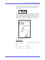
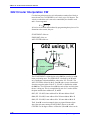
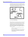
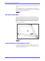
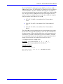
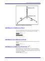
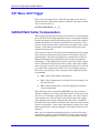
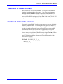
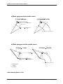
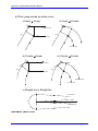
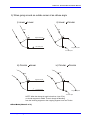
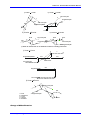
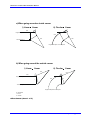
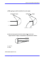
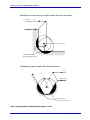
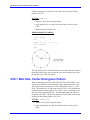
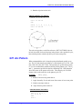
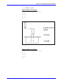
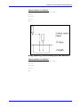
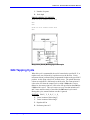
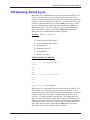
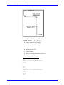
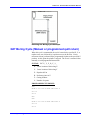
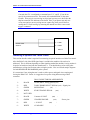
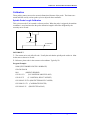
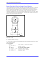
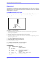
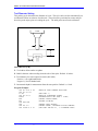
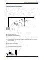
PMAC-NC Technical Documentation Manual
G02 Circular Interpolation CW
Circular interpolation uses the axis information contained in a block, to
move the tool in a CLOCKWISE arc of a circle, up to 360 degrees. The
velocity at which the tool is moved is controlled by the feedrate word
and is vector tangential:
Ft =
2
2
fx + f y .
All circles are defined and machined by programming three pieces of information to the control, they are
START POINT of the arc
END POINT of the arc
ARC CENTER of the arc
The START POINT is defined prior to the G02 line, usually by a G01
linear positioning move. The END POINT is defined by the X and Y
axis coordinates within the G02 line when in the XY - PLANE. The
ARC CENTER is defined by the I, J and K values (vector incremental
from the start point) when in the X-Y - PLANE, or the R value within
the G02 line. The full format for a G02 line must reflect in which plane
the arc is being cut. This is accomplished by use of a G code to define
the plane and the letter addresses I, J, and K.
G17 (XY - PLANE) Letter address I for X Letter address J for Y
G18 (XZ - PLANE) Letter address I for X Letter address K for Z
G19 (YZ - PLANE) Letter address J for Y Letter address K for Z
The I, J and K vector incremental values are signed distances from
where the tool starts cutting (START POINT) the arc to the ARC
CENTER. For 90 degree corners or fillets the I, J and K values can be
3-16
NC 32 Bit for Lathe Application