1
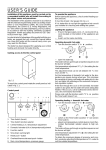
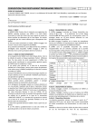
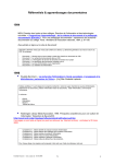
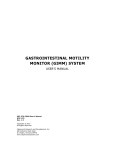
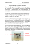
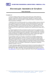
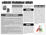
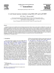
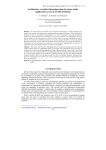
International Journal of Computer Applications (0975 – 8887)
Volume 29– No.7, September 2011
SMS based Load Shedding Period Control System
Dwijen Rudrapal
Assistant Professor
Dept. of Computer Sc. &
Engineering
National Institute of
Technology, Agartala
Jirania, Tripura (W). India
Smita Das
Swapan Debbarma
Goutam Pal
Assistant Professor, Dept. of
Computer Sc. & Engineering
National Institute of
Technology, Agartala
Jirania, Tripura (W). India
ABSTRACT
Energy is one of the basic requirements in modern civilization,
without which various indispensable applications will bind to
bring to a standstill. It is really not possible to measure the
actual enormity of the function that energy has accomplished in
connection with human advancement. As energy plays such a
significant role in our day-to-day life, hence we should confer a
precedence to accumulate it by the use of load shedding.
Conventional methods of load shedding systems are too slow to
calculate efficiently the accurate amount of load to be shed. This
consequences either excessive or insufficient load reduction. In
latest years, load shedding systems have been carried out using
conventional under-frequency relay and/or breaker interlocks
schemes incorporated with Programmable Logic Controllers to
give an innovative glance to an obsolete load preservation
methodology. In true sense, period of load shedding can be
controlled with a computerized power management system
where rapid and optimal load management can be done. Again,
the Computerized Load Shedding Control System can now be
extended and it can be controlled by a SMS based system. This
paper demonstrates the need for a modern load shedding scheme
and introduces the idea of developing a SMS based procedure
for controlling the load-shedding system where manual work
will be minimized by selecting the feeder, substation and
duration of shedding time by the user by sending SMS.
Simulation results‟, using the above proposed model, verifies the
suitability of choosing such a SMS based automated load
shedding period control system.
Keywords
Load Shedding; Energy; Electricity; SMS Based System;
Substation; Feeder; Shedding Time.
1. INTRODUCTION
Present-day civilization of the world is fully enriched with latest
technologies which are making our lives comfortable and
machine depended. But these entire technological products
around us are greatly utilizing electric power and most of the
world is not having enough electric power to meet our
requirements. Thus, we necessitate the suitable distribution of
electric power. Load shading [1] is an intentionally-engineered
electrical power [2] outage where electricity delivery is stopped
for non-overlapping periods of time over geographical regions.
For manually maintaining Load shading periods, some man
power may be employed or by using computer it can be
controlled efficiently. Detaching of power is done to minimize
the load being consumed by the society through several
substations which are connected to the main power station [3].
Assistant Professor
Dept. of Computer Sc. &
Engineering
Tripura Institute of
Technology, Agartala
Jirania, Tripura (W). India
And the main station instructs the sub-stations to cut some of the
feeders for a certain period of time & thus the shedding
procedure continues. In recent years, conventional under
frequency and PLC-based [4] load shedding schemes have been
integrated with computerized power management systems to
provide an “automated” load shedding system. It can provide
faster and optimal load relief by utilizing actual operating
conditions and knowledge of past system disturbances. The
main theme behind the proposed method is to replace the
computerized procedure for controlling the load-shedding time
period [5] by a SMS based system [6] where the shedding
management process, manual work may be minimized in a
systematic way. As we all know that any low cost mobile phone
is capable of sending text messages, hence this SMS based
shedding scheme will be very cheap and easy to operate and
having fewer complexities with a proper user friendly interface
provided by the system.
2. EXISTING
LOAD
SHEDDING
SCHEDULE MANAGEMENT
The purpose of an electric power system is to attach the power
stations to the consumers‟ loads by means of interconnected
system of transmission & distribution networks [7]. Therefore
an electrical power system consists of three principal
components:
1.
2.
3.
Power Station
Transmission Lines and
Distribution Systems.
In the shedding process, under a main power station there are
several sub-stations who perform power-cut for a certain period
of time to control the shortage of electrical energy used by the
people of the locality. In manual system of load shedding,
workers form the electrical authority are engaged in the
substations who attend the calls and directions from the main
power station & as per the upper levels direction, power system
of some area are manually cut down by the workers for a period
of time. And after the completion of those areas‟ shedding some
other areas are cut-off. In this way the shortage of electrical
energy is covered up by the electrical authority.
There were several conventional implementation of the above
mentioned manual load shedding scheme. This section depicts a
review of a number of load shedding systems that have been
developed earlier.
8
International Journal of Computer Applications (0975 – 8887)
Volume 29– No.7, September 2011
Individual consumer
Servic
e main
Distribution
substation
Power station
11 KV Feeder
11 KV
Transmission line
~
~
11 KV
Alternator
11KV/220 KV
Transformer
220KV/11 KV
Transmission substation
Fig. 1: Electric flow from power station to consumer
2.1 Breaker Interlock Scheme
The simplest system [8] carried out for load shedding control
had a source breaker, which would be interlocked via hardwired
or remote signals to a set of load breakers that have been preselected to trip. When a generator breaker or a grid connection is
lost for any reason, signals are automatically sent to load
breakers to open. This system is difficult to change load priority
since the actions for load shedding are hardwired and amount of
load shedding is calculated for the worst-case scenario.
2.2 Under Frequency Relay Scheme
Frequency relays [9] do not detect disturbances but react to
the disturbances. They detect either a rapid change in frequency
or gradual frequency deterioration and initiate staged operation
of interlocked breakers. When the first stage is reached, the relay
waits a predetermined amount of time, to avoid nuisance
tripping, and then trips one or more load breakers. This is done
to allow the frequency to recover. If the frequency continues to
decay, the relay will wait for the next stage to be reached and
after an additional time delay, opens other load breakers. This
system has a slow response time and also incorrect load may be
dropped causing undesirable shedding
2.3 PLC Based Scheme
In PLC-based load shedding scheme [10], load shedding is
initiated based on the system frequency deviations and/or other
triggers. The circuit breaker tripping can be programmed
based on the system loading, available generation, and other
specific logics. Each subsystem is equipped with a PLC that is
programmed to shed a preset sequence of loads. This static
sequence is continued until the frequency returns to a normal
condition. Modification of the logic requires changing of the
latter-logics that are programmed in the PLCs. The system-wide
operating conditions are often missing from the PLC‟s decisionmaking process resulting in insufficient or excessive load
shedding. In addition, the load shedding systems response time
during transient disturbances is often too long requiring for even
more load to be dropped.
Therefore, our paper focuses on developing a SMS based
procedure for controlling the load-shedding system which can
now be extended computerized Load shading system controlled
by remote communication through SMS.
3. PROPOSED
ARCHITECTURE
SYSTEM
Improvement in computational technologies has opened the
door for fast Load Shedding Controller (LSC) designs with low
cost, expediency, scalability and remote access capability. This
paper deals with designing such a computerized LSC which will
reduce manual effort for controlling the load shedding time
interlude in a systematic way by sending SMS. For this, the
following requirements are there:
3.1 Hardware Components
3.1.1 The proposed system needs the
following hardware components:
i) Photo transistor Optocouplers MCT2E
ii)BC107B NPN Transistor
iii) Resistor
iv) Protective relay mechanism & Manometer:
The relay circuit connection may be divided into three
parts: First part is a primary winding of a current transformer
which is connected in series with the line to be protected.
Second part consists a secondary winding of C.T. &
the relay coil. Third part is the tripping circuit [11] which may
be either A.C. or D.C. It consists of a source of supply, the trip
coil of the circuit breaker & the relay stationary contacts.
9
International Journal of Computer Applications (0975 – 8887)
Volume 29– No.7, September 2011
Fig. 2: A Model Circuit diagram for proposed system
When the short circuit occurs at point on the transmission line,
the current flowing in the line increases to a enormous value
resulting a heavy current flow through the relay coil, causing the
relay to operate by closing its contacts. This in turn closes the
trip circuit of the breaker, making the circuit breaker open &
isolating the faulty section from the rest of the system. Thus the
relay ensures the safety of the circuit equipment from damage.
3.2 Software Components
3.2.1 Introduction to the SMS based system:
SMS, stands for “Short Message Service”, is a technology that
enables the sending and receiving of messages between mobile
phones. SMS first appeared in Europe in 1992. It was included
in the GSM (Global System for Mobile Communications) [12]
standards right at the beginning. Later it was ported to wireless
technologies like CDMA and TDMA. As suggested by the name
"Short Message Service", one SMS can contain at most 140
bytes or 160 bytes (in case of 7-bit character encoding) of data.
SMS can be sending in two modes: i) Text mode ii) PDU
mode. Here SMS is send in Protocol Data Unit mode.
Fig. 3: User communication with system
3.2.3 How to send/receive SMS?:
In general, there are two ways to send SMS from a computer /
PC to a mobile phone:
1.
3.2.2 Turing Test:
The Turing test is a test of a machine's ability to exhibit
intelligent behavior. A human judge engages in a natural
language conversation with one human and one machine, each
emulating human responses. All participants are separated from
one another. If the judge cannot reliably tell the machine from
the human, the machine is said to have passed the test. In order
to test the machine's intelligence rather than its ability to render
words into audio, the conversation is limited to a text-only
channel such as a computer keyboard and screen.
To make the system easier the proposed model tries an
implementation of Turing test. As in the Turing Test [13] the
user find it difficult to understand whether he is communicating
with an human or computer, same in case of the proposed
system in the paper, the user will thought that he is actually
communicating with another person through SMS, unaware of
the fact that actually the system gets his request message, parses
it and based on some computation sends him back the result of
his query, all in an automated fashion.
2.
Connect a mobile phone or GSM/GPRS modem [14]
to a computer / PC. Then use the computer / PC and
AT commands to instruct the mobile phone or
GSM/GPRS modem to send SMS messages.
Connect the computer / PC to the SMS center (SMSC)
or SMS gateway of a wireless carrier or SMS service
provider. Then send SMS messages using a protocol /
interface supported by the SMSC or SMS gateway.
In this paper, the first concept is used and only with the help of
mobile phone SMS is send from PC.
3.2.4 Sending SMS from PC using mobile:
In the proposed model in this paper, the mobile phone is
connected through a USB cable. After connecting a mobile
phone to a computer, it can be controlled by sending instructions
to the mobile.
10
International Journal of Computer Applications (0975 – 8887)
Volume 29– No.7, September 2011
Fig. 4 Communication between mobile and system
through SMS
The instructions used for controlling the mobile phone are called
AT Commands [15]. Mobile phones support a common set of
standard AT commands and in addition mobile phones also
support an extended set of AT commands which are used to
control the sending and receiving of SMS.
Below shows a simple example that is used as AT commands
and the HyperTerminal program of Microsoft Windows to send
an SMS. The lines in bold are the command lines that should be
entered in HyperTerminal [16]. The other lines are responses
returned from the mobile phone.
AT
OK
AT+CMGF=1
OK
AT+CMGW="+85291234567"
> A simple demo of SMS text messaging.
+CMGW: 1
OK
AT+CMSS=1
+CMSS: 20
OK
Here is a small description of what is done in the above
example:
Line 1: "AT" is sent to the mobile to test the connection. The
mobile sends back the result code "OK”, which means the
connection between the HyperTerminal program and the mobile
works fine.
Line 3: “AT command + CMGF” is used to instruct the mobile
to operate in SMS text mode. The result code "OK" is returned
which indicates the command line has been executed
successfully.
If the result code "ERROR" is returned, it is likely that the
mobile does not support the SMS text mode. To confirm, type
"AT+CMGF=?" in the HyperTerminal program. If the response
is "+CMGF: (0,1)" (0=PDU mode and 1=text mode), then SMS
text mode is supported. If the response is "+CMGF: (0)", then
SMS text mode is not supported.
Line 5 and 6: “AT command +CMGW” is used to write an
SMS text message to the message storage of the mobile.
"+85291234567" is the recipient mobile phone number. After
typing the recipient mobile phone number, „Enter‟ button of the
keyboard has to be pressed. The mobile will then return a
prompt "> " and typing the SMS text can be started as "A simple
demo of SMS text messaging.” When typing is finished, press
“Ctrl+z” of the keyboard.
Line 7: "+CMGW: 1" tells us that the index assigned to the
SMS text message is 1. It indicates the location of the SMS text
message in the message storage.
Line 9: “AT command +CMSS” is used to send the SMS text
message from the message storage of the mobile. "1" is the
index of the SMS text message obtained from line 7.
Line 10: "+CMSS: 20" tells us that the reference number
assigned to the SMS text message is 20. And the result code
"OK" indicates the execution of the AT command +CMSS is
successful.
3.2.5 Using a PC to receive SMS through
mobile:
Below shows a simple example that demonstrates how to use
AT commands and the HyperTerminal program of Microsoft
Windows to read SMS text messages received by a GSM /
GPRS modem or mobile phone.
AT
OK
AT+CMGF=1
OK
AT+CMGL="ALL"
+CMGL: 1,"REC READ","+85291234567",”06/11/11,
00:30:29+32"
Hello, welcome to SMS tutorial.
+CMGL: 2,"REC READ","+85291234567",”06/11/11,
00:32:20+32"
>A simple demo of SMS text messaging.
OK
Here is a description of what is done in the above example:
Line 5-9: The AT command +CMGL is used to list all SMS text
messages in the message storage of the mobile. There are two
SMS text messages in the message storage: "Hello, welcome to
SMS tutorial." and "A simple demo of SMS text messaging.”
"+85291234567" is the sender mobile phone number. "06/11/11,
00:30:29+32" and "06/11/11, 00:32:20+32" tell us when the
SMS text messages were received by the SMS Centre. "+32" is
the time zone. Note that the unit is a quarter of an hour. So, +32
means GMT+8 hours, since 32 quarters of an hour = 8 hours.
"REC READ" indicates both of the SMS text messages have
been read before.
Line 11: The result code "OK" indicates the execution of the
AT command +CMGL is successful.
3.3 How the proposed system works:
For the successive execution of the proposed system, some step
by step procedure or algorithm is used to incorporate the load
shedding scheme. This is as following:
Step – 1: Select Substation from the grid present.
Step – 2: Select the feeder from the substation equipment list.
Step – 3: Make a choice of whether to turn it on or off.
Step – 4: For a particular feeder, the choice of switching it
on/off after specified duration is also possible.
Step – 5: Make final confirmation on the choice made.
11
International Journal of Computer Applications (0975 – 8887)
Volume 29– No.7, September 2011
In case of SMS based system in the above algorithms, we can
use some abbreviations representing the name of the
Substations, feeder or grid. Because we all know that the text
SMS will support only 160 characters in a single SMS.
Therefore, one can select the abbreviated names for a substation,
followed by grid and then the choice for turning it “ON” or
“OFF”. For simplicity, one can use the SMS as following:
<URT> <grd1> <ON>
or <KLT><grd2> <OFF>
These three fields in a SMS will be sent to the server, then SMS
will be parsed and analyzed by the server and reply will be given
back to ensure that selected portion is turned ON or OFF. Also,
one can send the duration along with substation and grid in
terms of minutes to make a specific duration of power cut.
For e.g. <KLT><gr2><OFF><30>
30 minutes to the said location.
will make a power cut of
4. SIMULATION USED TO DEPICT
THE SCHEME
Below some of the snapshots are given from the SMS based
Load Shedding Control System Simulator.
The electrical circuit arrangements, which are being done, can
be attached with the parallel port of the computer and with the
help of C program the Electrical Circuit can be controlled by the
Computer [17]. Therefore, once input data (feeder, substation,
time period of power cut etc.) will be selected with the help of
programming interface, automatically the whole setup will be
controlled by the software written in C language. The program
will then control the whole load shedding scheme.
Fig. 5: Selection of Input
Fig. 6: Selection of Substation
Fig. 7: Selection of Feeder
12
International Journal of Computer Applications (0975 – 8887)
Volume 29– No.7, September 2011
Fig. 10: Selection of Time Period of Power OFF
Fig. 8: Selection of Power ON/OFF
Fig. 11: Screen after entering the required time.
Fig. 9: Confirmation of Power ON/OFF
13
International Journal of Computer Applications (0975 – 8887)
Volume 29– No.7, September 2011
5. CONCLUSION AND FUTURE SCOPE
Due to the insufficiency of adequate power supply, electrical
authority used to shut power supply in different urban and rural
areas for proper distribution. To maintain this power shut down
periods in several areas at peak hours requires enough
manpower and continuous observations. The proposed system
along with remote communication with sms will be running
automatically and minimized a huge amount of manual work
and enhance efficiency to the existing manual system.
As the power shut down system is highly sensitive and under
strict control of the authority, the proposed system can be
extended with security implementation. To communicate
through sms and operate the system user will be asked for ID
and password. For enhancing the security the system will be
only operational with proper authentication. From server side
one administrator will maintain ID and passwords to designated
employees.
6. REFERENCES
[1] C. Concordia, L.H. Fink, and Geroge Poullikkas, “Load
shedding on an isolated system,” IEEE Trans. Power Syst.,
vol. 10, pp. 1467-1472, Aug. 1995.
[2] D. Guilfoyle, E. Connolly, “Distributed SCADA systems
for electricity distribution control,” Power Technology Int.,
pp. 169-172, 1994.
[3] C.Bouchoucha, N.mansouri, M.Annabi. Adaptation of the
production to the consumption of the electric power and
design of the adjustment in the grid systems. GEI2002,
March 2002
[4] High Fidelity Simulation Power System Dynamics; J.F.
Vernotte, P. Panciatici, B. Meyer, J.P. Antoine, J. Deuse
and M. Stubbe; (IEEE Computer Applications in Power,
1995).
[5] D. Rudrapal et. al. “Automated Load Shedding Period
Control Systems”, International Journal on Computer Sc. &
Engineering, Vol 3, Issue 5, pp. 1159 - 1168, May 2011.
Computing, Control & Telecommunc. Technologies,
December 2009.
[7] J.J. Ford, H. Bevrani, G. Ledwich, "Adaptive load shedding
and regional protection", International Journal of Electrical
Power & Energy Systems, Volume 31, Issue 10,
November-December 2009, Pages 611- 618.
[8] http://faculty.kfupm.edu.sa/EE/mderiche/downloads/farooq
.pdf
[9] www2.selinc.com/techpprs/6339_AppRedundLoadShed_N
S_20080929.pdf
[10] Tom Wilson, PLC Based Substation Automation and
SCADA Systems; Selecting a Control System Integrator,
Western Electric Power Institute, March 1999.
[11] S. J. Huang, and C. -C. Huang, “An adaptive load shedding
method with time-based design for isolated power
systems,” International Journal of Electrical Power &
Energy Systems, vol. 22, no. 1, January 2000, pp. 51-58.
[12] Yamamoto, R., Hideyuki, M., Hideo, M., Tomoyoshi, O. &
Hiroyuki, O., “Position Location Technologies Using
Signal Strength in Cellular Systems”, Vehicular
Technology Conference VTC 2001, Spring IEEE, VTS, 4
(53), PP. 2570-4, November 2001
[13] Copeland J. “The Turing Test”, Minds and Machines, Pg.
519-539.
[14] Wave-com Built-in GSM/GPRS modem,User Manual,
2001.
[15] Wavecom AT Commands Interface Guide, 2001, Version
001/9, November.
[16] Micrologic ML-250 handheld GPS receiver operator‟s
Manual, 1996. May.
[17] T. Leibfried, “Online monitor keeps transformer in
service,” in IEEE Computer Applications in Power, vol. 11,
July 1998, pp.36-42
[6] Mukhopadhyay T. and Bhattacharyya B. “Congestion in
SMS-Based Query-Response Mechanism – A Possible
Solution”, in International Conference on Advances in
14