1
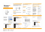
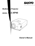
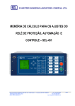
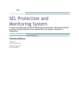
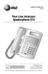
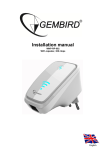
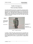
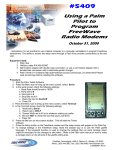
FreeWave Technologies
User Manual Addendum
FGR-115MB Mirrored Bit Radio Modem
Using the FGR-115MB in Mirrored Bit Applications
The FreeWave Technologies FGR-115MB Spread Spectrum transceiver is a
special version of the FGR-Series product family. It provides additional features
that are optimized for use with Schweitzer Engineering Labs Mirrored Bit
Communications in high-speed protective relay and other applications. The
FGR-115MB is a cost-effective, reliable, and secure alternative to optical fiber,
metallic pilot wire and other communications technologies for Mirrored Bit
communications.
The FGR-115MB contains all of the features and functions of the standard FGRSeries 900 MHz spread spectrum product family and may be used in any other
application where the standard products can be used with the exception of
applications using either Ethernet or the optional TDMA mode. Ethernet and
TDMA are not available on the FGR-115MB.
For use in Mirrored Bit applications, specific settings must be made to the FGR115MB as described in this addendum. The three parts of this addendum
explain the setup of a point-to-point Mirrored Bit link, the setup of a Mirrored Bit
link with one repeater hop, and troubleshooting techniques for mirrored bit links.
Refer to the FGR-115RC User Manual for more information on programming the
FGR-115MB for applications where Mirrored Bit communication is not used.
Part 1. Programming a point-to-point Mirrored Bit Link
Connect an ASC0409 DC Programming/Diagnostics cable from the Diagnostics
port on the FGR-115MB to the serial port on the programming terminal. Set up
the programming terminal as described in the FGR-Series user manual. Invoke
the setup menu by pressing the SETUP button on the radio’s rear panel or by
sending an uppercase U from the programming terminal. Programming must be
done through the Diagnostics port. The programming menu will not be displayed
through the radio’s RS-232 port.
SETUP button
RS-232 port
(main)
Diagnostics port
Figure 1. FGR-115MB rear panel
LAD0006AB Rev A
1
FreeWave Technologies
User Manual Addendum
FGR-115MB Mirrored Bit Radio Modem
The radio’s main menu will be displayed as shown in Figure 2 below. The three
LEDs on the radio’s front panel will be green. When the radio is in setup mode,
the radio link is disconnected and data will not pass through the link.
Figure 2. Main Menu
1.1 Set Operation Mode
Enter a 0 (zero) to open the Set Operation Mode menu. The menu will be
displayed as shown in Figure 3 below.
A point-to-point Mirrored Bit
communication link requires two radios. One radio must be set to be the
Mirrorbit Master (an entry of A in the Operation Mode menu). The other radio
must be the Mirrorbit Slave (an entry of B). Although the entry is made as either
an A or B, the Modem Mode indication at the top of the menu page will be 10 for
Mirrorbit Master or 11 for Mirrorbit Slave. When the entry has been made, press
ESC to return to the main menu.
LAD0006AB Rev A
2
FreeWave Technologies
User Manual Addendum
FGR-115MB Mirrored Bit Radio Modem
Figure 3. Operation Mode Menu
Select A or B
1.2 Set Baud Rate
Enter 1 from the Main Menu to open the Set Baud Rate menu. The menu will be
displayed as shown in Figure 4 below. For Mirrored Bit operation, the Baud Rate
on each radio must be set to either 9,600 or 38,400 (entry 4 or 6 in the Baud
Rate menu). These are the only baud rate selections that are valid for Mirrored
Bit operation. Each radio must be set to match the baud rate of the Mirrored Bit
device to which it is connected and both radios must be set to the same baud
rate. For optimum Mirrored Bit performance, a baud rate of 38,400 is
recommended.
The Setup Port must be set to 2 (Diag only). To change the Setup Port, select
Setup Port (menu item D). The Setup Port menu will be displayed as shown in
Figure 5 below. Enter 2 (For Diag Only) as shown.
When the baud rate and Setup Port entries have been made, press ESC to
return to the main menu.
LAD0006AB Rev A
3
FreeWave Technologies
User Manual Addendum
FGR-115MB Mirrored Bit Radio Modem
Figure 4. Baud Rate Menu
Select 9,600 or 38,400
Figure 5. Setup Port Menu
Change Setup Port to Diag only
LAD0006AB Rev A
4
FreeWave Technologies
User Manual Addendum
FGR-115MB Mirrored Bit Radio Modem
1.3 Edit Call Book
Enter 2 from the Main Menu to open the Edit Call Book menu. When using a pair
of FGR-115MB radios in a Mirrored Bit application, each radio must have the
other radio's serial number as the first entry in its Call Book with no entries in the
Repeater1 and Repeater2 columns as shown in Figure 6 below. In addition, the
Mirror Bit Master must be programmed to call the first entry in its Call Book.
To make a call book entry, enter a 0 (zero) and, at the prompt, enter the sevendigit serial number of the other radio in the link. Do not enter the dash character.
At the Enter Repeater1 prompt, press ESC to complete the entry. Do not use the
Repeater1 and Repeater2 prompts to enter repeater serial numbers. Refer to
Part 2 of this addendum for instructions on programming Mirrored Bit repeaters.
The Mirrored Bit Slave will not establish communication with the master by
turning Slave Security off. The Slave must have the Mirrored Bit Master's serial
number as the first entry in its call book.
Figure 6. Edit Call Book Menu
When the call book entry is complete, press ESC to return to the main menu.
LAD0006AB Rev A
5
FreeWave Technologies
User Manual Addendum
FGR-115MB Mirrored Bit Radio Modem
1.4 Edit Radio Transmission Characteristics
From the Main Menu, enter 3 to open the Edit Radio Transmission
Characteristics Menu as shown in Figure 7 below. All values in the Radio
Parameters menu must be identical for the Mirrored Bit master and the Mirrored
Bit slave radios with the exception of RF Xmit Power (menu item 5) and High
Noise (menu item A). For more information on these functions refer to the
FreeWave FGR-Series User Manual. MCU Speed (menu item B) must be set to
1. If more than one pair of FreeWave 900MHz transceivers are operating in
close proximity they must be set to different Frequency Keys (menu item 0). This
is also necessary if the radios are to be configured as a Mirrored Bit repeater.
Refer to Part 2 of this addendum for instructions on programming a Mirrored Bit
repeater.
Unlike the DGR-Series Mirrored Bit radios, it is not necessary to change Hop
Table Size on the FGR-115MB for Mirrored Bit operation. Hop Table Size should
be left at its standard setting of 112.
Figure 7. Radio Transmission Characteristics Menu
Use different FreqKey settings to
avoid interference. Master and Slave
must be set to the same value.
Set MCU Speed to 1
When the radio parameters entries are complete, press ESC to return to the
main menu.
1.5 Edit MultiPoint Parameters
From the Main Menu, enter 5 to open the Edit MultiPoint Parameters Menu as
shown in Figure 8 below. For Mirrored Bit operation without a repeater, 1 PPS
LAD0006AB Rev A
6
FreeWave Technologies
User Manual Addendum
FGR-115MB Mirrored Bit Radio Modem
Enable/Delay must be set to 255. If 1 PPS Enable/Delay is set to any other
value, change it to 255. Press ESC to return to the main menu.
Figure 8. Edit MultiPoint Parameters Menu
Set 1 PPS Enable/Delay
to 255
Press ESC again to exit the setup menu and return the FGR-115MB to operation
mode. The Mirrored Bit link is now ready to transmit Mirrored Bit data. Connect
the antenna connector on each radio to its antenna system. Connect the comm.
Port on each radio to its Mirrored Bit device using a straight through RS-232
cable. (An RS-232 gender changer may be required to connect the RS-232
cable to the Mirrored Bit device.) Refer to Part 3, troubleshooting, if the link does
not function properly.
Figure 9 shows a typical Mirrored Bit installation between an SEL 351R and
351S using FGR-115MB radios. Many other configurations are possible.
LAD0006AB Rev A
7
FreeWave Technologies
User Manual Addendum
FGR-115MB Mirrored Bit Radio Modem
Figure 9. Typical Mirrored Bits Installation
LAD0006AB Rev A
8
FreeWave Technologies
User Manual Addendum
FGR-115MB Mirrored Bit Radio Modem
Typical Equipment List
The following equipment list details the typical components and connections for
each end of a Mirrored Bit link, as shown in Figure 9 above. A pole, tower, or
other means of elevating the antenna is not shown. SEL relays or other Mirrored
Bit devices are not included.
Typical Equipment List
Qty
Item
Description
2
900 MHz SpreadSpectrum
Transceiver
FreeWave Technologies, Inc. Model FGR115MB.
6 to 30 volt dc power, 1 W output, 20+ miles
line-of-sight, 120 Vac-to-12 Vdc adapter, 6’
DB-9M-to-DB-9F straight-through cable and
DB-9 male-to-male gender changer
included. (An SEL C285 cable can be used
directly without adaptors if desired.)
2
Yagi Antenna
FreeWave Technologies, Inc. 1 Model
EAN0900YC.
10 dB, directional, 26” long.
$195
2
Low-Loss RF
Cable
FreeWave Technologies, Inc. 2 Model
ASC1004NN.
100’ length
$185
2
Fiber-Optic
Transceiver
SEL 3 Model SEL-2800M.
EIA-232 DB-9M-to-Fiber-Optic Transceiver.
$102
1
Fiber-Optic Cable
SEL 3 Model C800FZ.
Terminated Cable, 25’ or less (other lengths
available)
$60
1
DB-9 Null Modem
Adapter
FreeWave Technologies, Inc Model
ECD0009NM 9 pin male to 9 pin female Null
Modem Adapter, or equivalent (one end is
male, one end is female)
$7
2
Surge Protection
Northern Technologies, Model QWS-920N 4.
N Type M-to-F ¼ shorting stub coaxial
protector tuned for 870 - 970 MHz.
www.northern-tech.com
(800) 727-9119
$135
LAD0006AB Rev A
9
Approx.
Cost
$1,350
FreeWave Technologies
User Manual Addendum
FGR-115MB Mirrored Bit Radio Modem
Notes:
1. Other antennas are available.
2. Other RF cable lengths are available.
3. Other fiber-optic transceivers and cable may be used. Note, the
fiber-optic transceivers are not required, but provide complete
isolation between the radio and antenna and the relay.
4. Other surge protection may be used (PolyPhaser, etc.). FreeWave
recommends northern Technologies for use with their radios.
Other Notes
1. In Mirrored Bits mode, the FGR-115MB may be used with a number of
different SEL devices, please contact SEL at www.selinc.com for a complete
list of supported devices.
2. When the FGR-115MB is used for Mirrored Bits communication, one repeater
may be used in the link. Refer to Programming A Mirrored Bits repeater in
this addendum for more information.
3. When the FGR-115MB is used for Mirrored Bits communication, it is not
compatible with the models DGR-115RU or DGR-115RXU Mirrored Bit radios
if these radios are also being used for Mirrored Bits communications.
Otherwise, the FGR-115MB is compatible with any DGR or FGR-Series
radios when used in standard point-to-point or point-to-multipoint modes.
Part 2. Programming a Mirrored Bit Repeater
Unlike a standard FreeWave point-to-point or point-to-multipoint repeater, which
requires only one radio, a Mirrored Bit repeater uses two radios in a “back-toback” configuration. One of these radios is a Mirrored Bit slave and the other
radio is a Mirrored Bit master. Each of these radios communicates with another
radio at another location in a point-to-point Mirrored Bit link. The master at the
repeater site communicates with a remote Mirrored Bit slave radio. The slave at
the repeater site communicates with a remote Mirrored Bit master radio. Follow
the instructions in Part 1 of this addendum to first set up each of the
separate Mirrored Bit links. Set each of the separate Mirrored Bit links on a
different frequency key to minimize interference at the repeater site. Follow the
instructions in Part 2 only for the radios to be installed at the repeater site.
LAD0006AB Rev A
10
FreeWave Technologies
User Manual Addendum
FGR-115MB Mirrored Bit Radio Modem
2.1 Set Baud Rate
Enter 1 from the Main Menu to open the Set Baud Rate menu as shown in Figure
10 below. For Mirrored Bit repeater operation, the Baud Rate on each radio in
the repeater pair must be set to 230,400 (entry 0 (zero) in the Baud Rate menu).
This is the only baud rate selection that is valid for Mirrored Bit repeater
operation. Do not change the baud rate settings of the other radios that will be
linked to the master and slave radios at the repeater site. These radios must be
set to match the baud rate of the Mirrored Bit devices to which they are
connected and both of these radios must be set to the same baud rate.
When the baud rate entry has been made, press ESC to return to the main
menu.
Figure 10. Set Baud Rate Menu
Set to 230,400
2.2 Edit Multipoint Parameters
Enter 5 from the Main Menu to open the Edit Multipoint Parameters menu as
shown in Figure 11 below. For Mirrored Bit repeater operation 1 PPS
Enable/Delay (Menu Item 9) must be changed from its normal setting of 255 to a
new setting of 0. Do not change the 1 PPS Enable/Delay settings of the other
radios that will be linked to the master and slave radios at the repeater site.
LAD0006AB Rev A
11
FreeWave Technologies
User Manual Addendum
FGR-115MB Mirrored Bit Radio Modem
Figure 11. Edit MultiPoint Parameters Menu
Set to 0
When 1 PPS Enable/Delay has been set to 0, press ESC to return to the Main
Menu. Press ESC again to exit the setup menu and return the radio to operation
mode.
Connect the data ports on the master and slave radios at the repeater site with
an RS-232 null modem cable. Connect both radios to their separate antenna
systems. The radios are now ready to function as a Mirrored Bit repeater. See
Figure 12 below. If Mirrored Bit communications cannot be established through
the repeater, refer to Part 3, troubleshooting, at the end of this addendum.
LAD0006AB Rev A
12
FreeWave Technologies
User Manual Addendum
FGR-115MB Mirrored Bit Radio Modem
Figure 12. Mirrored Bit Repeater Configuration
Antenna
20 Miles, Line-of-Sight
Antenna
Freewave FGR-115MB
Transceiver
(slave 1)
M-to-M Null Modem Adapter
FreeWave FGR-115MB
Transceiver
(master 1)
DB-9M–DB-9F Straight-Through
Cable
DB-9M–DB-9F Straight-Through
Cable
Freewave FGR-115MB
Transceiver
(master 2)
M-to-F Straight-Through
Adapter
SEL-351S-7 Relay
(RXID=1, TXID=2)
20 Miles, Line-of-Sight
Antenna
Antenna
FreeWave FGR-115MB
Transceiver
(slave 2)
DB-9M–DB-9F Straight-Through
Cable
M-to-F Straight-Through
Adapter
SEL-351S-7 Relay
(RXID=1, TXID=2)
LAD0006AB Rev A
13
FreeWave Technologies
User Manual Addendum
FGR-115MB Mirrored Bit Radio Modem
Typical Equipment List for Mirrored Bit Repeater
Qty
Item
Description
Approx.
Cost
2
900 MHz SpreadSpectrum
Transceiver
FreeWave Technologies, Inc. Model FGR-115MB.
6 to 30 volt dc power, 1 W output, 20+ miles line-ofsight, 120 Vac-to-12 Vdc adapter, 6’ DB-9M-to-DB9F straight-through cable and DB-9 male-to-male
gender changer included. (An SEL C285 cable can
be used directly without adaptors if desired.)
$1,350
2
Yagi Antenna
FreeWave Technologies, Inc. 1 Model EAN0900YC.
10 dB, directional, 26” long.
$195
2
Low-Loss RF
Cable
FreeWave Technologies, Inc. 2 Model ASC1004NN.
100’ length
$185
1
DB-9 Null Modem
Adapter
FreeWave Technologies, Inc Model ECD0009NM 9
pin male to 9 pin female Null Modem Adapter, or
equivalent (one end is male, one end is female)
$7
2
Surge Protection
Northern Technologies, Model QWS-920N 4.
N Type M-to-F ¼ shorting stub coaxial protector
tuned for 870 - 970 MHz.
www.northern-tech.com
(800) 727-9119
Notes:
1. Other antennas are available.
2. Other RF cable lengths are available.
3. Other surge protection may be used (PolyPhaser, etc.). FreeWave
recommends northern Technologies for use with their radios.
Part 3. Troubleshooting
The front panel LEDs are very useful in quickly determining the current condition
of the FGR-115MB. The table below shows the most common conditions.
Condition
CD
Powered and
connected
SG
LAD0006AB Rev A
Master
TR
CTS
SR
SR
14
CD
SG
Slave
TR
CTS
SR
SR
$135
FreeWave Technologies
User Manual Addendum
FGR-115MB Mirrored Bit Radio Modem
Powered and
connected, weak link
Powered, disconnected
Powered and
connected but on
different Freq Keys
Setup Mode
SG
SR
IF
SG
SR
IF
SR
SR
SR
SR
O
BR
SG/
SR
(altern
ating)
SG
SR
(on
and
off)
SG
IF
SG
IF
SR
SG
SG
SG
SG
Legend:
BR
IF
O
SG
SR
Blinking Red
Intermittent Flash Red
Off
Solid Green
Solid Red, Bright
Symptom
Radio is not linked, CD
LED is red.
Possible Cause
Radio on other end of
link is not powered
Radio on other end of
link in setup mode
Incorrect programming
Obstructions blocking
signal path
Excessive interference
Excessive interference
Radio is linked but no
communications between
Mirrored Bit devices
Incorrect baud rate or
comm. Port settings
Radio connected to
wrong port on Mirrored
Bit device
LAD0006AB Rev A
15
Solution
Apply power to other
radio
Check that other radio is
not in setup mode.
Recheck programming
Relocate antennas to
provide clearer radio path
or consider using a
repeater.
Turn on High Noise
feature in Radio
Parameters Menu.
Install EBF900 bandpass
filter
Recheck that baud rate
settings on Mirrored Bit
devices match baud rate
setting on radios. Verify
that Mirrored Bit devices
are set to 9600 or 38400
bps and MB8A protocol.
Make sure that radios are
connected to correct port
on Mirrored Bit device.
FreeWave Technologies
User Manual Addendum
FGR-115MB Mirrored Bit Radio Modem
Incorrect serial cable
connection
Mirrored Bit
communications log
shows numerous errors
If repeater is used, cable
connection between
repeater radios is
incorrect
Local noise and
interference
Unavailability log is less
than .001. See Figure
13 below
Excessive local
interference,
Unavailability log shows
more than .001.
LAD0006AB Rev A
16
Check that radios are
connected to Mirrored Bit
devices with straight
through RS-232 cable. If
fiber optic transceiver is
used, make sure that null
modem adapter is used
between radio and
transceiver.
Connect serial ports on
radios at repeater site
with null modem cable.
Check Unavailability
Mirrored Bit device
comm. Log. Noise and
interference will cause
numerous short-term
errors but will not affect
reliability of
communications. Typical
outage will last less than
10 ms. Unavailability will
be less than .001.
Check radio performance
with point-to-point
diagnostics program.
Use High Noise feature or
EBF900 filter or both.
Check for noise sources
in area.
FreeWave Technologies
User Manual Addendum
FGR-115MB Mirrored Bit Radio Modem
Failure log shows
outages lasting longer
than 50 ms
LAD0006AB Rev A
17
Check radio performance
with point-to-point
diagnostics program.
Use High Noise feature or
EBF900 filter or both.
Check for noise sources
in area. Relocate
antennas to reduce
interference or to
increase signal strength.
Change antenna
polarization. Make sure
distance between sites
does not exceed
maximum operating
range of radios. Consider
using a repeater.
FreeWave Technologies
User Manual Addendum
FGR-115MB Mirrored Bit Radio Modem
Figure 13. SEL Communications Log.
Point-to-Point Diagnostics
The FreeWave Point-to-Point Diagnostics Program allows continuous monitoring
of the performance of a Mirrored Bit link without disrupting the operation of the
link. The program is included on the CD-ROM containing the FGR-115MB user
manual and this addendum. The program may be run on either the Mirror Bit
master or the Mirror Bit slave radio.
Locate the diagnostics program on the disk file and open the program. Connect
the ASC0409DC Programming/Diagnostics cable between the Diag port of the
FGR-115MB and the Comm Port on the computer. Select the Communication
menu and click Open Comm if the comm. Port to be used is Comm 1.
Otherwise, click on Chg Comm port to select a comm. Port other than Comm 1.
LAD0006AB Rev A
18
FreeWave Technologies
LAD0006AB Rev A
User Manual Addendum
FGR-115MB Mirrored Bit Radio Modem
19
FreeWave Technologies
User Manual Addendum
FGR-115MB Mirrored Bit Radio Modem
To change the comm. Port select Chg Comm port.
To start the program, select Open Comm.
LAD0006AB Rev A
20
FreeWave Technologies
User Manual Addendum
FGR-115MB Mirrored Bit Radio Modem
Select any comm. Port from 1 to 8.
The diagnostics program displays three screens of information. Navigation to
each screen is done by entering the number of the screen, 1, 2, or 3.
Diagnostics Screen 1
Screen 1 displays real-time graphs of antenna reflected power (VSWR) versus
frequency (green line) and transmit current versus frequency (red line).
A reflected power indication of 20 or higher indicates a possibly defective
antenna system.
The transmit current will vary with the radio’s dc supply voltage. Typical values
are 350 ma at 6 volts dc, 175 ma at 12 volts dc and 90 ma at 24 volts dc.
The dip in the middle of the graph represents frequencies on which data is not
transmitted. For this reason, the displayed values at these frequencies are
always displayed as zero and should be ignored.
LAD0006AB Rev A
21
FreeWave Technologies
User Manual Addendum
FGR-115MB Mirrored Bit Radio Modem
Diagnostics Screen 1
Diagnostics Screen 2
Screen 2 displays real-time graphs of percent receive rate versus frequency
(blue line), received signal level versus frequency (green line), noise level versus
frequency (red line) and peak noise level versus frequency (yellow line).
For reliable Mirrored Bit operation, an average receive rate of 80% or higher is
recommended. The receive rate is effected by received signal strength and by
noise and interference.
The average signal level indicates how well that this radio hears the radio on the
other end of the link. The values displayed are – dBm. A displayed value of 100
is higher than a value of 110. The program does not display the minus sign. For
reliable Mirrored Bit operation, a level of 90 or higher is recommended.
The noise level is also displayed in –dBm. For reliable Mirrored Bit operation, a
noise level at least 20 below the average signal level is recommended.
LAD0006AB Rev A
22
FreeWave Technologies
User Manual Addendum
FGR-115MB Mirrored Bit Radio Modem
The peak noise trace captures and holds the transient noise that is detected by
the radio. This provides an indication of interference sources in the area even if
the interference is not steady state.
Diagnostics Screen 2
Diagnostics Screen 3
Screen 3 of the diagnostics program provides a continuous plot of radio link
performance versus time. The time scale begins when the diagnostics program
is started (time 0) and automatically rescales as the program runs with the most
recent data on the left end of the plot.
Error % (blue line) records the percentage of bad packets that were received and
discarded. This is the inverse of the percent good shown in screen 2.
Signal Lv, (green line) is the received signal strength in –dBm.
Noise Lv, (red line) is the noise level at the radio’s input in -dBm.
Xmit Rate, (brown line) is the transmitted data transfer speed in kB/sec.
Rcvd Rate, (orange line) is the received data transfer speed in kB/sec.
LAD0006AB Rev A
23
FreeWave Technologies
User Manual Addendum
FGR-115MB Mirrored Bit Radio Modem
Diagnostics Screen 3
Contacting FreeWave
FreeWave Technologies
1880 S. Flatiron Ct.
Boulder, CO 80301
Phone: (800) 548-5616
Fax: (303) 786-9948
www.freewave.com
Technical Support Center hours 8 AM to 5 PM Mountain Time Monday through
Friday.
LAD0006AB Rev A
24