1
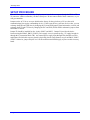
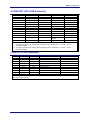
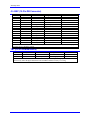
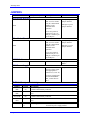
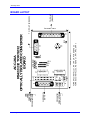
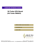
^1 USER MANUAL
^2 Accessory 26A
^3 Serial Communications Converter
^4 3Ax-602213-xUxx
^5 October 15, 2003
Single Source Machine Control
Power // Flexibility // Ease of Use
21314 Lassen Street Chatsworth, CA 91311 // Tel. (818) 998-2095 Fax. (818) 998-7807 // www.deltatau.com
i
Copyright Information
© 2003 Delta Tau Data Systems, Inc. All rights reserved.
This document is furnished for the customers of Delta Tau Data Systems, Inc. Other uses are
unauthorized without written permission of Delta Tau Data Systems, Inc. Information contained in
this manual may be updated from time-to-time due to product improvements, etc., and may not
conform in every respect to former issues.
To report errors or inconsistencies, call or email:
Delta Tau Data Systems, Inc. Technical Support
Phone: (818) 717-5656
Fax: (818) 998-7807
Email: [email protected]
Website: http://www.deltatau.com
Operating Conditions
All Delta Tau Data Systems, Inc. motion controller products, accessories, and amplifiers contain
static sensitive components that can be damaged by incorrect handling. When installing or handling
Delta Tau Data Systems, Inc. products, avoid contact with highly insulated materials. Only
qualified personnel should be allowed to handle this equipment.
In the case of industrial applications, we expect our products to be protected from hazardous or
conductive materials and/or environments that could cause harm to the controller by damaging
components or causing electrical shorts. When our products are used in an industrial environment,
install them into an industrial electrical cabinet or industrial PC to protect them from excessive or
corrosive moisture, abnormal ambient temperatures, and conductive materials. If Delta Tau Data
Systems, Inc. products are directly exposed to hazardous or conductive materials and/or
environments, we cannot guarantee their operation.
Accessory-26A
Contents
INTRODUCTION .......................................................................................................................................................1
SELECTING THE CORRECT OPTION .................................................................................................................3
SETUP PROCEDURE ................................................................................................................................................5
OPERATING ACC-26A .............................................................................................................................................7
CONNECTORS ...........................................................................................................................................................9
J1 JRS422 (26 Pin Connector).......................................................................................................................................9
J2 JRS232AT (9 Pin DB Connector).............................................................................................................................9
J3 JRS232XT (25 Pin DB Connector).........................................................................................................................10
4 JRS232 (10 Pin Connector) ......................................................................................................................................10
J5 JGEF (15-Pin DB Connector) .................................................................................................................................11
TB1 (2 Pin Terminal Block) ........................................................................................................................................11
JUMPERS ..................................................................................................................................................................13
Serial Data Direction ..............................................................................................................................................13
Handshake Direction...............................................................................................................................................13
SMCC Init/ ..............................................................................................................................................................13
TB1 Power Supply...................................................................................................................................................13
E-Point Jumper Summary............................................................................................................................................13
BOARD LAYOUT.....................................................................................................................................................15
Table of Contents
i
Accessory-26A
Table of Contents
ii
Accessory-26A
INTRODUCTION
PMAC’s Accessory 26A is a new version of the serial communication optical isolation board for all
versions of PMAC. It replaces the old ACC-26, which was suitable only for the PMAC-PC and the
PMAC-VME. In the new version, ACC-26A Option 1 can be used for optical isolation of the host
computer’s RS-232 to PMAC's RS-422 connector J4 (this is suitable for the PMAC-PC, PMAC-VME,
and PMAC-LITE equipped with Option 9L). ACC-26A Option 2 is suitable for the regular PMAC-LITE
and the PMAC-STD32 (The cable is not provided for PMAC-STD32). Option 2 simply acts as an optical
isolation board between the host's RS-232 and the PMAC’s RS-232 connectors. ACC-26A Option 3
provides, through its J5 (JGEF) connector, optical isolation of the serial communication link between a
host computer and the GE-FANUC series 90-70 PLC. ACC-26A Option 4 may be used for Delta Tau's
other motion control cards (SMCC and MCC).
The board comes with a standard DIN-rail mounting system, or you can use the four corner holes to
mount the board with standoffs.
Both DB-9 and DB-25 connectors are provided for host connection.
Introduction
1
PMAC Accessory 26A
Introduction
2
Accessory-26A
SELECTING THE CORRECT OPTION
When ordered as ACC-26A Option 1, this board comes equipped for RS-232 to RS-422 conversion and
optical isolation. In this configuration, IC U1 plus resistor packs RP1 and RP2, are installed; IC U2 is not
installed. ACC-26A Option 1 should be ordered for optically isolated host serial communication to the
PMAC-PC, PMAC-VME and PMAC-LITE with its Option 9L. A 26-pin flat cable is provided for
connecting this accessory's J1 connector to the PMACs' RS-424 connector (J4 on PMAC-PC and PMACVME).
When ordered as ACC-26A Option 2, this board comes equipped for RS-232 to RS-232 optical isolation.
In this configuration, IC U2 is installed; IC U1 and the resistor packs RP1 to RP3 are not installed.
Option 2 should be ordered for optically isolated host serial communication to the regular PMAC-LITE
(one without its Opt. 9L) and PMAC-STD32. A 10-pin flat cable is provided for connecting this
accessory's J4 connector to PMAC-LITE board's RS-232 connector (J4). For PMAC-STD32, a separate
cable should be special ordered.
When ordered as ACC-26A Opt. 3 this board comes equipped for RS-232 to RS-422 conversion and
optical isolation. In this configuration, IC U1 plus resistor packs RP1 and RP3 are installed; IC U2 is not
installed. ACC-26A Opt. 3 should also be ordered for communication between any RS-232 host and the
GE FANUC series 90-70 PLC. A DB15S connector cable is provided for connection to the GE FANUC
series 90-70 PLC.
When ordered as ACC-26A Option 4, this board comes equipped for RS-232 to RS-232 optical isolation.
In this configuration, IC U2 is installed; IC U1 and the resistor packs RP1 to RP3 are not installed.
Option 4 should be ordered for optically isolated host serial communication to SMCC and MCC. A 26pin flat cable is provided for connecting this accessory's J1 connector to SMCC’s J2 connector and
MCC’s JRS232 connector.
Selecting the Correct Option
3
PMAC Accessory 26A
Selecting the Correct Option
4
Accessory-26A
SETUP PROCEDURE
The ACC-26 requires very little setup. Simply connect it to the host computer through the DB-9 or DB25 connector; whichever matches your host's serial port. Do not connect both of these connectors, or you
will get contention.
Jumpers on the ACC-26 are set up as default at the factory for the typical way a PC uses the serial
communications lines (as the commanding device). If this is not the way your host device works, you can
exchange the RXD and TXD lines by changing the E1A and E1B jumpers from horizontal to vertical, and
exchange the RTS and CTS lines by changing the E1C and E1D (E2A & E2B in schematic) jumpers from
horizontal to vertical.
Jumper E3 should be installed for Opt. 4 only (SMCC and MCC). Jumper E4 provides the choice
between using the PMAC, SMCC or MCC power supply verses a separate power +5V supply brought in
through the 2-pin terminal block TB1. An external power supply input through TB1 should be used for
applications in which this accessory board is physically placed a long distance away from PMAC, SMCC
or MCC. Otherwise, jumper E4 pins 2 to 1 for the motion control board supply of power to this accessory
board.
Setup Procedure
5
PMAC Accessory 26A
6
Setup Procedure
Accessory-26A
OPERATING ACC-26A
The ACC-26A requires no software setup, and can handle any baud rate up to PMAC’s maximum. Once
installed and operational, it is transparent to the user.
There are four dual-color LEDs on the ACC-26A to show when the key communications lines are being
used. Each LED is red when the corresponding line is not in use, and green when it is in use. LED D1 is
for the RXD/ line, D2 is for the TXD/ line, D3 is for CTS, and D4 is for RTS. (These are the only lines
that PMAC requires for serial communications; the ACC-26A shorts together the DSR and DTR lines for
those hosts that require a return pulse on one, for a pulse on the other). These lamps can be used to
troubleshoot communications problems. Lamp D5 is a green LED that is on when the card is receiving
power.
Operating ACC-26A
7
PMAC Accessory 26A
8
Operating Acc-26A
Accessory-26A
CONNECTORS
J1 JRS422 (26 Pin Connector)
Pin
Symbol
Function
Description
Notes
1
CHASSI
Common
PMAC Common
2
S+5V
Output
+5Vdc supply deactivated by E8 on PMAC
3
RDInput
Receive Data
Diff. I/O low TRUE
4
RD+
Input
Receive Data
Diff. I/O high TRUE
5
SDOutput
Send Data
Diff. I/O low TRUE
6
SD+
Output
Send Data
Diff. I/O high TRUE
7
CS+
Input
Clear to Send
Diff. I/O high TRUE
8
CSInput
Clear to Send
Diff. I/O low TRUE
9
RS+
Output
Request to Send
Diff. I/O high TRUE
10
RSOutput
Request to Send
Diff. I/o low TRUE
11
DTR
Bidirection
Data Terminal Ready
Tied to DSR
12
INIT/
Input
PMAC Reset
Low is RESET
13
CND
Common
PMAC Common
14
DSR
Bidirection
Data Set Ready
Tied to DTR
15
SDIOBidirection
Special Data
Diff. I/O low TRUE
16
SDIO+
Bidirection
Special Data
Diff. I/O high TRUE
17
SCIOBidirection
Special Ctrl. Diff.
I/O low TRUE
18
SCIO+
Bidirection
Special Ctrl. Diff.
I/O high TRUE
19
SCKBidirection
Special Clock
Diff. I/O low TRUE
20
SCK+
Bidirection
Special Clock
Diff I/O high TRUE
21
SERVOBidirection
Servo Clock
Diff. I/O low TRUE
22
SERVO+
Bidirection
Servo Clock
Diff I/O high TRUE
23
PHASEBidirection
Phase Clock
Diff. I/O low TRUE
24
PHASE+
Bidirection
Phase Clock
Diff I/O high TRUE
25
GND
Common
PMAC Common
26
+5V
Output
+5VDC Supply
This connector should be used to connect ACC-26A to the PMAC-PC and PMAC-VME board's J4
connector via the supplied 26-pin flat cable for ACC26A OPT. 1. Also, for ACC-26 OPT 4, this connector
provides the link to SMCC and MCC boards.
J2 JRS232AT (9 Pin DB Connector)
Pin
Symbol
Function
Description
Notes
1
DCD
NC
Data Carrier Detect
Not used
2
RXD/
Output*
Receive Data
Low is TRUE
3
TXD/
Input*
Transmit Data
Low is TRUE
4
DTR
Bidirection
Data Terminal Ready
Connected to DSR
5
GND
Common
PMAC Common
6
DSR
Bidirection
Data Set Ready
Connected to DTR
7
RTS
Input**
Request to Send
8
CTS
Output**
Clear to Send
9
RI
NC
Ring Indicator
Not used
This connector is used for connection to a host computer's RS232 connector through a DB9's connector.
*
To change signal direction, change E1A/E1B jumpers from "horizontal" to "vertical". See the
enclosed schematic.
**
To change signal direction, change E2A/E2B jumpers from "horizontal" to "vertical." See the
enclosed schematic.
Connectors
9
PMAC Accessory 26A
J3 JRS232XT (25 Pin DB Connector)
Pin
Symbol
1
2
3
4
5
6
7
8
9
10
11-19
20
TXD/
RXD/
RTS
CTS
DSR
GND
INIT/
DTR
Function
NC
Input*
Output*
Input**
Output**
Bidirection
Common
NC
NC
Input
NC
Bidirection
Description
Notes
Transmit Data
Receive Data
Request to Send
Clear to Send
Data Set Ready
PMAC Common
PMAC Reset
Data Terminal
Ready
Not connected
Low is TRUE
Low is TRUE
Connected to DTR
Not connected
Not connected
Low is RESET
Not connected
Connected to DSR
21-25
NC
Not connected
This connector is used for connection to a host computer's RS232 connector through a DB25 connector.
* To change signal direction, change E1A/E1B jumpers from "horizontal" to "vertical". See the
enclosed schematic.
** To change signal direction, change E2A/E2B jumpers from "horizontal" to "vertical". See the
enclosed schematic.
4 JRS232 (10 Pin Connector)
Pin
Symbol
Function
Description
Notes
1
PHASE
NC
Phase Clock
Not used
2
DTR
Bidirection
Data Terminal Ready
Connected to DSR
3
TXD/
Output
Transmit Data
Low is TRUE
4
CTS
Input
Clear to Send
5
RXD/
Input
Receive Data
Low is TRUE
6
RTS
Output
Request to Send
7
DSR
Bidirection
Data Set Ready
Connected to DTR
8
SERVO
NC
Servo Clock
Not used
9
GND
Common
PMAC Common
10
+5V
Input
+5V DC Supply
This connector should be used to connect ACC-26A to PMAC-LITE ‘s J4 connector via the supplied flat
cable for ACC26A Option 2
10
Connectors
Accessory-26A
J5 JGEF (15-Pin DB Connector)
Pin
Symbol
Function
Description
Notes
1
SHIELD
Common
Cable Shield
Connected to GND
2
NC
No connection
3
NC
No connection
4
NC
No connection
5
+5V
Input
Power Supply
6
-RTS(A')
Output
Request to Send/
7
GND
Common
GE Fanuc Common
8
+CTS(B)
Output
Clear to Send
9
NC
No connection
10
-RD(A)
Input
Read Data/
11
+RD(B)
Input
Read Data
12
-SD(A')
Output
Send Data/
13
+SD(B')
Output
Send Data
14
+RTS(B')
Input
Request to Send
15
-CTS(A)
Output
Clear to Send/
This connector should be used to connect ACC-26A to the GE FANUC series 90-70 PLC. For this purpose
ACC26A OPT. 3 should be ordered.
TB1 (2 Pin Terminal Block)
Pin
Symbol
Function
Description
Notes
1
GND
Common
2
+5V
Input
Power Supply
This connector should be used to connect ACC-26A to separate local power supply. This connection is
not necessary unless the physical distance between PMAC and this accessory is too long.
Connectors
11
PMAC Accessory 26A
12
Connectors
Accessory-26A
JUMPERS
E Point
Physical Layout
Description
Default
Connect E1A 1 to 2 and
E1B 1 to 2 for normal
host (PC) and terminal
(PMAC) serial
communication
operation.
E1A pin 1 to pin 2
jumper installed
Serial Data Direction
E1A
E1B
E1B pin 1 to pin 2
jumper installed
For reverse protocol,
connect E1A pin 1 to
E1B pin 1 and E1A pin
2 to E1B pin 2.
Handshake Direction
E2A
Connect E2A 1 to 2 and
E2B 1 to 2 for normal
host (PC) and terminal
(PMAC) serial
communication
operation.
E2B
E2A pin 1 to pin 2
jumper installed
E2B pin 1 to pin 2
jumper installed
For reverse protocol,
connect E2A pin 1 to
E2B pin 1 and E2A pin
2 to E2B pin 2.
SMCC Init/
E3
No jumper installed for
PMAC
TB1 Power Supply
E4
Connect E4-2 to E4-1
for power supply input
from appropriate J
connector (J1, J4 or J5).
Jumper 1-2 installed
For power supply input
from Terminal Block
TB1, connect E4-2 to
E4-3
E-Point Jumper Summary
Jumper
On/off
E1A
E1B
E1A to
E1B
E1C (E2A)
E1D (E2B)
E1C to
E1D
E3
E4
On
On
Jumpers
On
On
1-2
2-3
Description
Default settings for standard RXD & TXD serial communication lines.
Considered horizontally connected.
Connect these “vertical” to each other to switch RXD & TXD communication
lines.
Default settings for standard RTS & CTS serial communication lines.
Considered horizontally connected.
Connect these “vertical” to each other to switch RTS & CTS communication
lines.
Installed only for Option 4 (SMCC & MCC).
Power supply select
PMAC, SMCC, MCC (default)
External 5V power supply needed
13
PMAC Accessory 26A
14
Jumpers
(REQUIRES SPECIAL CABLE)
PMAC-Lite
PMAC-STD32
GE FANUC
90-70
MCC
SMCC
PMAC-PC
PMAC-VME
PMAC-Lite RS422
J4
1
E3
TB1
1 2
E4
1
J1
U1
U2
RTS TXD/
CTS RXD/
E1D
E1A
4.25 in. (107 mm.)
RP3
RP2
RP1
1
T1
J2
FOR RS-422 INSTALL U1, RP1, RP2, RP3, REMOVE U2
FOR RS-232 INSTALL U2, REMOVE U1, RP1, RP2, & RP3
1
J5
MC34050
MAX232
Board Layout
D10
1
J3
TO PC-XT
(RS232C)
TO PC-AT (RS232C)
3.88 in. (98.55 mm)
ACC-26A
RS422/232 TO RS232
OPTICALLY ISOLATED CONVERTER
BOARD
Accessory-26A
BOARD LAYOUT
15
PMAC Accessory 26A
16
Board Layout