1
DPI 520 User Manual
i
DPI 520
RACK MOUNTED PRESSURE CONTROLLER
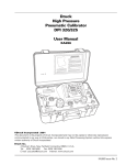
DPI 520 Pressure Controller
Software Issue
This User Manual supports Software Issue No. 3.XX
© Druck Limited 1998
This document is the property of Druck Limited and may not, either in part or whole, be copied or
otherwise reproduced, communicated in any way to third parties, or stored in any Data Processing
System, without the express written authority of Druck Limited.
K163 Issue No. 3
DPI 520 User Manual
ii
SAFETY
The Manufacturer has designed this product to be entirely safe when operated
correctly.
●
Please pay close attention to the Safety Instructions outlined on this page and
elsewhere in this manual. They have been designed to protect the user from
personal injury and the equipment from damage.
●
Potentially hazardous operations are indicated in the text by
means of a hazard warning triangle. Specific warnings
relating to each section of the manual are given at the
beginning of that section. On the instrument, this symbol
indicates that the user should refer to the User Manual.
●
Please observe the installation advice and any operational limits given in this
manual.
●
This equipment must only be used for the purpose for which it was designed
Pressure Safety
Do not permit pressures greater than the Safe Working Pressure to be applied to
the instrument. The specified Safe Working Pressure for the instrument is stated
in the Specification section of this manual.
Electrical Safety
The instrument is designed to be completely safe when used with Options and
Accessories supplied by the manufacturer for use with the instrument.
Toxic Materials
During normal operation it is not possible for the user to come into contact with any
hazardous substance which might be employed in the construction of the instrument. The use of hazardous materials in the construction of this instrument has
been minimised.
K163 Issue No. 3
Safety
iii
Repair and Maintenance
This publication contains information and warnings which must be followed for safe
operation and to maintain the equipment in a safe condition. Use qualified*
personnel and good engineering practice for all procedures in this publication.
The operator must not use this equipment for any other purpose than that stated.
Do not apply a pressure greater than the maximum pressure stated.
*
A qualified person must have attended a product training course given by the
manufacturer or appointed agent and successfully completed the training
course on this equipment.
This product meets the essential protection requirements of the
relevant EEC directives. Further details of applied standards may
be found in the product specification.
K163 Issue No. 3
DPI 520 User Manual
iv
ABBREVIATIONS
NOTE: Abbreviations are the same in the singular and plural.
ac
atm
°C
°F
COM
cm2
contd
dc
DMM
DUT
ENT
FS
ft
kg
LSD
Pa
PIN
mA
mH2O4
mm
MSD
N/C
No.
PRESS
PTX
RDG
RS 232
SCPI
T
VAC
K163 Issue No. 3
alternating current
atmosphere
degrees Celsius
degrees Fahrenheit
common
centimetre squared
continued
direct current
digital multimeter
device under test
enter
full-scale
feet
kilogram
Least significant digit
Pascal
personal identification number
milli Amperes
metres of water at 4°C
milli metres
most significant digit
No Connection
number
pressure
pressure transmitter
reading
serial data transmission standard
Standard command for programmable
instrumentation
tare
vacuum
Contents
Section
v
Page
1
1.1
1.2
1.2.1
1.2.2
1.2.3
INTRODUCTION ............................................................................................. 1-1
Instrument Specification .................................................................................. 1-2
Applications ..................................................................................................... 1-6
Control by Remote Computer via IEEE 488 ........................................ 1-6
Control by Remote Computer via RS232 ............................................ 1-7
Control by Remote User Interface ....................................................... 1-7
2
2.1
2.2
2.2.1
2.2.2
FUNCTIONAL DESCRIPTION ........................................................................ 2-1
General ............................................................................................................ 2-1
Instruments Electronics ................................................................................... 2-1
Digital Electronics ................................................................................ 2-1
Analogue Circuit Operation .................................................................. 2-3
3
3.1
3.1.1
3.1.2
3.2
3.2.1
3.2.2
3.3
3.4
3.4.1
3.4.2
3.5
3.5.1
3.5.2
3.6
3.7
3.8
3.8.1
3.8.2
3.8.3
3.8.4
3.8.4
3.9
3.9.1
3.9.2
INSTALLATION ............................................................................................... 3-1
Safety Instruction ............................................................................................ 3-1
Input/Output Connections .................................................................... 3-1
Rack Mounting ..................................................................................... 3-1
Electrical Connections .................................................................................... 3-3
Electrical Safety Instructions ................................................................ 3-3
Power Supply Connections .................................................................. 3-3
Communications Interface Connections ......................................................... 3-5
IEEE 488 Interface .......................................................................................... 3-5
Single Unit Installation ......................................................................... 3-7
Multiple Unit Installation ....................................................................... 3-8
RS232 Interface .............................................................................................. 3-9
General ................................................................................................ 3-9
Connecting to a Computer ................................................................... 3.11
Connection of Remote User Interface ............................................................. 3-18
Analogue Output Socket ................................................................................. 3-18
Pressure Connections ..................................................................................... 3-19
Pressure Safety Instructions ................................................................ 3-19
Connection ........................................................................................... 3-19
Obtaining the Best Performance ..................................................................... 3-23
Maximising Valve Life .......................................................................... 3-24
Control at Zero Gauge Pressure without a Vacuum Pump ................. 3-25
Set-up Mode .................................................................................................... 3-26
General ................................................................................................ 3-26
Set-up MENU ....................................................................................... 3-28
Keyboard (Unlocked) ................................................................ 3-28
Recall defaults ........................................................................... 3-29
Set-up controller ........................................................................ 3-30
Set PIN ....................................................................................... 3-32
Show S/W Revision .................................................................. 3-33
Self Test Electronic .................................................................... 3-33
Self Test Pneumatic ................................................................... 3-34
Set-up COMMUNICATIONS ................................................................ 3-36
Set-up More (Scale, Zero, More) ......................................................... 3-45
More (Set-point and Rate) ................................................................... 3-47
3.9.3
3.9.4
3.9.5
.
K163 Issue No. 3
DPI 520 User Manual
vi
Section
4
4.1
4.2
4.3
4.3.1
4.3.2
4.4
4.4.1
4.4.2
4.4.3
4.4.4
4.4.5
4.4.6
4.4.7
4.4.8
4.4.9
4.4.10
4.4.11
4.4.12
4.4.13
4.4.14
4.4.15
4.4.16
4.4.17
4.4.18
4.4.19
4.4.20
4.5
4.6
4.6.1
4.6.2
4.7
4.7.1
4.7.2
4.7.3
4.7.4
4.7.5
4.7.6
Page
OPERATION ................................................................................................... 4-1
Local Mode ...................................................................................................... 4-1
Remote Mode .................................................................................................. 4-1
Control Codes ................................................................................................. 4-1
Control Code Format ........................................................................... 4-2
Implementation of checksums ............................................................. 4-3
Command Description ..................................................................................... 4-6
Set to Local Mode - 'M' ........................................................................ 4-6
Set Mode - 'R' ...................................................................................... 4-6
Set Scale Unit - 'S' ............................................................................... 4-7
Units - 'U' .............................................................................................. 4-7
Data Select - 'D' ................................................................................... 4-7
Output Data Format - 'N' ...................................................................... 4-7
Interrrupt -'I' ......................................................................................... 4-9
Wait - 'W' ............................................................................................. 4-9
Controller On/Off - 'C' ........................................................................... 4-10
Pressure Set-Point - 'P' ........................................................................ 4-10
Ratio - '/' ............................................................................................... 4-10
Preset - '*' ............................................................................................. 4-10
Error Reporting On/Off - '@' ................................................................. 4-11
Rate - 'J' ............................................................................................... 4-11
Zero Instrument - '01' ........................................................................... 4-11
Rate value - 'V' ..................................................................................... 4-11
Isolation Valve Open/Close - 'E' ......................................................... 4-11
Open Isolation valve - 'F' ..................................................................... 4-12
Tare value - 'B' ..................................................................................... 4-12
Tare On/Off - 'T' ................................................................................... 4-12
Output Code Format ....................................................................................... 4-13
Parameter Definitions .......................................................................... 4-14
Error Status Code ................................................................................ 4-18
RS232 Specific ................................................................................................ 4-19
Operation Using RS232 ....................................................................... 4-19
Direct mode ................................................................................. 4-20
Printer Mode ............................................................................... 4-21
Addressed Mode ......................................................................... 4-21
RS232 Output Code Format ................................................................ 4-24
Operation Using IEEE 488 .............................................................................. 4-26
Serial Poll ............................................................................................. 4-27
Standard IEEE Commands .................................................................. 4-27
IEEE Bus Time-out .............................................................................. 4-27
RS232 Command Specific Commands ............................................... 4-28
DPI 500 Mode ...................................................................................... 4-28
ASCII Values ........................................................................................ 4-29
Continued.....
K163 Issue No. 3
Contents
Section
vii
Page
5
5.1
5.2
5.2.1
5.3
5.3.1
5.3.2
5.4
5.5
5.6
CALIBRATION ................................................................................................ 5-1
Calibration Check ............................................................................................ 5-1
Calibration Adjustment .................................................................................... 5-2
General Procedures ............................................................................. 5-3
Using the Calibration Menu ............................................................................. 5-4
Test ...................................................................................................... 5-4
Calibration (Cal) ................................................................................... 5-5
Checking Linearity Calibration ........................................................................ 5-6
Full Scale and Zero Adjustment ...................................................................... 5-7
Non-Linearity Adjustment ................................................................................ 5-8
6
6.1
6.2
6.3
6.4
6.5
6.5.1
6.5.2
6.6
MAINTENANCE .............................................................................................. 6-1
Safety Instructions ........................................................................................... 6-1
Fuse Replacement .......................................................................................... 6-2
Replace Vent, Source and Outlet Manifold Filters .......................................... 6-4
Cleaning .......................................................................................................... 6-4
Fault Finding ................................................................................................... 6-4
Error Codes .......................................................................................... 6-5
Controller Fault .................................................................................... 6-6
Approved Service Agents ................................................................................ 6-7
K163 Issue No. 3
viii
K163 Issue No. 3
1: Introduction
1
1-1
INTRODUCTION
Description
The DPI 520 is a programmable pneumatic pressure controller intended for
applications in automatic pressure testing and calibration.
A rugged Druck piezo resistive transducer measures pressure and is compensated to standard or enhanced accuracy as required.
Dual loop control provides extremely accurate and repeatable setting of pressure
output.
The Druck pneumatic control actuator achieves this level of control whilst also
providing fast response and very low gas supply consumption.
Only 2U of 19 inch rack is required to house the unit which is controlled remotely
by a host computer for fully automatic applications or from one of the range of
Remote User Interfaces for manual or semi-automatic applications
Pressure demands via a digital interface are converted by the controller into a
regulated pressure supplied from a line or bottle source. Both RS232 and IEEE 488
interfaces are provided as standard. The controller module has both control and
measure modes. Up to three controllers may be ‘stacked’ and controlled from a
single User Interface or computer.
Two levels of accuracy enhancement are available as Options A1 and A2.
Option B provides negative pressure calibration.
The controller is interchangeable with a DPI 510 at IEEE and RS232
communications level. Essentially the DPI 520 is compatible with the Druck control
software products InteCal and ACS.
A remote User Interface (RUI 100 and RUI 101) is available giving manual control
and display on one, two or three DPI 520 in a 'stacked' system. In this way, control
is provided to a high accuracy over a wide pressure range. See the RUI 100/101
Product Note for details.
K163 Issue No.3
1
DPI 520 User Manual
1-2
1.1
Instrument Specification
Pressure Ranges
Output Pressure
............................................................................................. 0 to 70 bar absolute
............................................................................................... -1 to 70 bar gauge
maximum 2 bar line pressure on gauge units
Maximum Safe Working Pressure
..................................................................................... 125 % full scale pressure
Source Pressure Range
Positive pressure ............................................................. 105 to 115 % full scale
Negative pressure ............................................... Lowest pressure used less 5%
Accuracies
Assuming regular zeroing of the instrument, the following figures apply.
Combined non-linearity, hysteresis and repeatability
Standard Instrument ................................................................ ± 0.05% full scale
Option A1 .................................................................. Refer to Options, Page 1-5
Option A2 .................................................................. Refer to Options, Page 1-5
Temperature Coefficient
The temperature coefficient averaged over 10° to 30°C.
Standard Instrument ......................................................... ± 0.01 % Reading/°C.
Options A1 and A2 .................................................... Refer to Options, Page 1-5
Stability
NOTE:
The following figure indicates 90 day stability and assumes
regular use of the zero facility.
............................................................................................. ± 0.015% of reading
Negative Pressures - Option B
Specification as per positive pressure but calculated as a percentage of the
positive full scale.
Controller Performance
Controller Stability ............................................................ ± 40 ppm of Full Scale
Fill Rate ............................................................ Dependant upon system volume
K163 Issue No. 3
1: Introduction
1-3
Electrical Specification
Power Supplies
A.C. Supply Voltage ............................................................................88 to 264 V
Supply Frequency ...............................................................................47 to 65 Hz
Power .......................................................................................................... 60 VA
Communications Interfaces
The controller provides two digital communications channels, an RS232 and an
IEEE 488 channel. Three RS232 connections are provided but all of these access
a single processor port.
Analogue Output
Type ...................................................... Single ended D.C. voltage, representing
controller output pressure, referenced to instrument ground.
Bandwidth .................................................................................. 2000 Hz to -6 dB
Ranges
Fixed, to order with full scale output in one of the following ranges:
........................................................................ 0 to 2V; 0 to 4V; 0 to 5V; 0 to 10V
Accuracy ..................................................................................... ± 0.3% full scale
Temperature Error Band .................................................. ±0.5% F.S., 0° to 40°C.
Source Impedance .................................................................................. < 1000Ω
Input/Output Connections and Controls (Rear Panel)
Pneumatic Connections
Source, Vent and Outlet .................................................................. G1/8 (female)
Reference .......................................................................................... M5 (female)
Electrical Connections
Analogue Output ....................................... BNC connector - centre +ve, shell -ve
Host (RS232) ............................. 9-pin, D-type connector, wired for point to point
RS232 on pins 2 and 3
User Interface (RS232) ....................................................9-pin, D-type connector
for connection to Druck rack mounting Remote User
Interface. Daisy chained to RS232 port. Supplies 24V
D.C. supply for Remote User Interface.
IEEE 488 .......................................................................... Standard GPIB socket.
A.C. Power ....................................... IEC 320 connector. Line (L) and Neutral (N),
individually fused within socket.
K163 Issue No.3
1
DPI 520 User Manual
1-4
Electrical Controls
Stacking Switch..................................... Controls use of RS232 interface.
Calibration ............................................. Switch (located under calibration label),
used only during instrument calibration.
Input/Output Connections (Front Panel)
Electrical Connections
User Interface (RS232) ......................................................... 6-way Lemo socket
for connection to Druck Desktop Remote User Interface, Type RUI 100.
Daisy chained to RS232 port with automatic bypass when not in use. Supplies
24V d.c. for the user interface.
Environmental Specification
Temperature
Operating ......................................................................................... 0° to +40°C
Operating (compensated) ............................................................ +10° to +30°C
Storage ......................................................................................... -20° to +60°C
Protection
Front panel ................................................................................................to IP40
EMC
Meets: ........................................................................... EN 50081-1 (emissions)
....................................................................................... EN 50082-1 (immunity)
Safety
Meets: .............................................................................................. EN 61010-1
Pressure Media
.......................................................................................................clean, dry gas
Weight
................................................................................................................... 5.2 kg
Dimensions
............................................ 90 mm (high), 482 mm (wide) and 360 mm (deep)*
*
Indicates case depth. Add 40 mm for the depth of handles.
K163 Issue No. 3
1: Introduction
1-5
Options
Option A1
Combined non-linearity, hysteresis and repeatability
........................................................ ±0.05% of reading (20% to 100% full scale)
............................................................. ±0.01% of full scale (0 to 20% full scale)
Temperature Coefficient
.....................................................±0.002% rdg/°C (averaged over 10° to 30°C)
Option A2
Combined non-linearity, hysteresis and repeatability
...................................................... ±0.025% of reading (20% to 100% full scale)
........................................................... ±0.005% of full scale (0 to 20% full scale)
Temperature Coefficient
.....................................................±0.002% rdg/°C (averaged over 10° to 30°C)
Option B
Negative Calibration
Error as a percentage of +ve full scale. Value depending on the accuracy option
chosen.
Accessories
The instrument is despatched with the following items:
User Manual (K163)
Calibration Certificates
Power Supply Lead
K163 Issue No.3
1
DPI 520 User Manual
1-6
1.2
APPLICATIONS
1.2.1 Control by Remote Computer via IEEE 488
Using the IEEE 488 general purpose control bus, a remote computer can control
either a single stand alone unit or a number of units up to a maximum of 15. When
controlling a number of instruments each instrument on the bus is allocated a
unique address (set with the instrument via a SETUP facility). Each instrument is
first addressed and then instructed by means of control codes to carry out the
required functions (e.g.) mode change, output pressure change, rate change or
send current output pressure.
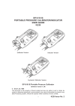
A special application of this mode of control allows the output pressure ports of a
number of controllers to be connected together into a common manifold. By using
instruments with different control pressure ranges, this permits a wide range of
accurately controlled pressures to be applied to a common manifold.
Figure 1.1 shows the general arrangement. Section 3 contains details for the
installation of this configuration of instruments.
Figure 1.1 - Control by Remote Computer via IEEE 488
K163 Issue No. 3
1: Introduction
1-7
1.2.2 Control by Remote Computer via RS232
●
PC to Instrument
A single instrument is connected directly to a computer and communications
can be controlled either by full hardware handshaking or software handshaking.
Section 3, Installation, details the connection method for both options.
●
Instrument to Printer
A stand alone instrument can be connected to a non-intelligent terminal or a
printer. In this mode the instrument provides a continuous flow of data, on a
timed basis. Interconnection details are the same as for the connection of a
control computer and are given in Section 3.
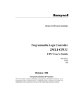
1.2.3 Control via Remote User Interface
Two types of Druck Remote User Interface can be used to control up to three DPI
520 instruments. These remote interface units, types RUI 100 (desk top) and RUI
101 (rack mounted), plug into special user interface sockets, located on the front
and rear panels respectively.
The Remote User Interface is automatically powered as soon as it is plugged into
a controller.
The RUI assumes that the controllers have a common pressure output. Using
instruments with different pressure ranges permits a wide range of accurately
controlled pressures to be applied to a single outlet.
Figure 1.2 shows the general arrangement. Refer to K181 for details of RUI 100/
101 connections.
K163 Issue No.3
1
DPI 520 User Manual
1-8
Figure 1.2 - Control from a Remote User Interface
K163 Issue No. 3
2:
Functional Description
2
FUNCTIONAL DESCRIPTION
2.1
General
2-1
The DPI 520 instrument is a single channel pressure controller, designed to be
programmed either from an external computer system or remote user interface.
No user controls are provided on the instrument, it’s local keyboard being used only
for set-up, calibration and maintenance operations. The use of these functions are
described in Sections 4 and 5 respectively.
Digital programming of the instrument is effected via a RS232 serial interface or
via an IEEE 488 parallel interface. The instrument can be configured in a number
of different ways as detailed in Section 1. Section 3 details the installation
procedures.
2.2
Instrument Electronics
2.2.1 Digital Electronics (Fig 2.1)
The instrument draws it’s power supplies from an internal power supply unit which
is, in turn, powered from an external a.c. source.
An internal microprocessor system controls the RS232 and IEEE 488
communications channels. One RS232 port is provided and one IEEE 488
channel. The RS232 port has three inputs, one of which is used for host
communications. The other two are used for the connection of either the Druck
RUI 101 (rack mounted) or the RUI 100 (desktop) Remote User Interfaces.
Although there are three RS232 connectors on each instrument, (one RS232 and
two User Interfaces), effectively they access only a single RS232 processor port.
A switching network has auto detection of the presence of a Remote User Interface
(RUI), plugged into one or other of the RUI sockets.
K163 Issue No. 3
2
DPI 520 User Manual
2-2
The microprocessor system also controls the flow of data to the instrument’s
display. The display is a two line (20 characters/line) liquid crystal dot matrix type.
Operationally, it is used to display pressures, functions and messages.
A keyboard, linked to the microprocessor, provides a user interface for set-up and
calibration purposes only. It is not used for normal operation, all operational
commands being sent via one of the two communications interfaces.
Control of the Analogue to Digital (A-D) Converters used in the analogue and valve
control circuits is effected via the microprocessor system’s bi- directional control
bus. A simplified description of the analogue control channel follows.
Figure 2.1 - Digital Electronics, Functional diagram
K163 Issue No. 3
2:
Functional Description
2-3
2.2.2 Analogue Circuit Operation (Fig 2.2)
Output pressure control is effected by means two solenoid operated valves. One
of these valves, the Apply valve, controls the application of a source pressure to
the output manifold. The other valve, the Release valve, releases the output
pressure. The output pressure is controlled by modulating the drive to each of
these valves, controlling their relative on/off times. An Isolation valve, also
controlled by the microprocessor, is used to isolate the controller from the external
pneumatic system. The controller output pressure (external system pressure
when the isolation valve is open), is measured by a suitably scaled, internally
mounted, pressure transducer.
Pressure demands to the controller are sent via either the RS232 or IEEE 488
communications interface and decoded by the microprocessor. The decoded
demand is sent to the setpoint A-D converter, processed (with other loop control
terms) and applied to an error amplifier. The other input to the error amplifier is the
transducer output signal, (representing the actual pressure at the controller
output).
The error amplifier produces a bipolar error signal proportional to the magnitude
and direction of the error between the setpoint demand and the actual output of the
controller. This error is first processed by an error signal processing circuit, under
the control of the microprocessor, to drive a pulse width modulator. The output of
the pulse width modulator drives the Apply and Release valves to change the
output pressure in an appropriate direction to correct the error i.e. to equalise the
setpoint demand and pressure feedback signals. A temperature feedback signal
from the output manifold, modifies the drive to the output valves should they
become overheated.
An analogue signal, proportional to the output pressure, is derived from the output
of the pressure sensing transducer. The output of the pressure transducer is
scaled by an amplifier/buffer and filtered before outputting from the instrument as
a d.c. signal. The gain of the output amplifier is set during manufacture to provide
one of four scaled ranges (refer to Section 1 - Specification).
K163 Issue No. 3
2
DPI 520 User Manual
2-4
Figure 2.2 - Analogue Electronics, Functional Diagram
K163 Issue No. 3
3:
Installation
3
INSTALLATION
3.1
Safety Instruction
3-1
IT IS ESSENTIAL THAT THE INSTALLATION OF
ELECTRICAL AND PNEUMATIC SUPPLIES BE
UNDERTAKEN BY A COMPETENT PERSON.
INSTALLATION REQUIREMENTS
1. THE INSTRUMENT IS DESIGNED TO BE RACK
MOUNTED IN A STANDARD 19" RACK OR SUBRACK AND OCCUPIES 2U OF SPACE.
2. PROVISION MUST BE MADE FOR A FLOW OF AIR
THROUGH THE VENTILATION SLOTS ABOVE AND
BELOW THE INSTRUMENT.
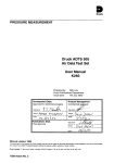
3.1.1 Input/Output Connections (Fig. 3.1 and 3.2)
All connections to the instrument, with the exception of an alternative Remote User
Interface connection, located on the front panel, are made to the rear panel of the
instrument. Fig 3.1 shows a diagram of a typical rear panel layout, together with
the electrical and pressure connections.
3.1.2 Rack mounting
To install the instrument in a standard 19" rack, proceed as follows:
❍ If the instrument has been previously installed, isolate and disconnect
all power supplies.
❍ Isolate all pressure supplies and disconnect all pressure inlet and
outlet connections.
❍ Remove any electrical connectors connected to the instrument (e.g.) RS232
and IEEE 488 connectors.
❍ Before installing, make sure that there is enough length of cable and pipe
for the installation and removal of the instrument.
❍ Connections are made at the rear of the instrument, allow enough space for
the cables and the pipes when the instrument is pushed back and secured
in the rack. It is important to allow cooling air to flow through the instrument.
K163 Issue No. 3
3
DPI 520 User Manual
3-2
2
1
5
6
7
8
9
11
10
12
Key to figures 3.1 and 3.2
1
3
5
7
9
11
IEC connector
2
fuse holder
4
small bore connector (G1/8)
6
reference connector (M5)
8
user interface connector (rear panel) 10
IEEE 488 interface connector
12
IEC power supply socket assembly
fuse
large bore connector (G1/8)
analogue output connector
RS232 interface connector
user interface connector (front panel)
Figure 3.1 - DPI 520 Rear Panel Connections
K163 Issue No. 3
3:
3.2
Installation
3-3
Electrical Connections
3.2.1 Electrical Safety Instructions
IT IS IMPORTANT TO USE THE CORRECT SUPPLY SETTINGS. OPERATING VOLTAGE RANGES
ARE MARKED ON THE REAR PANEL OF THE
INSTRUMENT AND ARE GIVEN IN SECTION 1,
SPECIFICATION.
It is essential that the Earth lead (coloured green/yellow) is connected to the a.c.
Supply Protective Safety Earth.
Before making any electrical connections to the rear panel, isolate the incoming
power supply.
Before removing any covers, isolate the instrument from all its supplies.
3.2.2 Power Supply Connections (Fig. 3.1 and 3.2)
The instrument is powered from a.c. mains. Section 1, Specification, gives full
details of the power supply requirements.
●
A.C. Power Supply
The a.c. power supply socket assembly (2) is located on the rear panel as
shown on Fig 3.1. A fuse (4) is also contained within the power supply socket
assembly (2), details of the fuse fitting being shown in Fig 3.2.
K163 Issue No. 3
3
DPI 520 User Manual
3-4
2
1
COOLING
AIR
FLOW
4
4
3
Fig 3.2 A.C Power Supply Socket
K163 Issue No. 3
3:
Installation
3-5
To connect the a.c. power supply, proceed as follows.
❍ Insert the moulded IEC connector (1) into the power supply socket assembly
(2) and connect to a suitable a.c. power source. Refer to Section 1,
Specification for power supply details.
❍ Switch on the a.c. power source.
❍ Check that the display is on.
❍ If the instrument display does not come on, isolate the external power supply
and remove the IEC connector (1) from the power supply socket assembly
(2).
❍ Remove the fuse carrier (3) as shown in Fig 3.2, insert one or two new fuses
(4) as required and refit the fuse carrier. Fuses are Type T2A, rated at 250V,
2 Amps.
❍ Reconnect the IEC connector (1) and switch on the power supply and the
instrument. The display should now come on.
❍ Switch off the power supply to the instrument.
3.3
3.2)
3
Communications Interface Connections (Fig. 3.1 and
Both the RS232 and IEEE 488 interfaces, through one or other of which the
instrument is controlled, are connected by polarised connector plugs (10 and 11).
To connect up the interfaces, fit the appropriate connectors into the relevant
sockets and tighten up the securing screws. The following sections describe the
connection to an external controller and the interconnection of the communications channel between a number of instruments.
3.4
IEEE 488 Interface (Fig. 3.3)
The IEEE 488 General Purpose Interface Bus (GPIB), is a parallel interface used
to connect a host computer/controller to one or more DPI 520 instruments and
possibly other instruments. A typical system is shown in Figure 3.3. To connect
a number of instruments together, the IEEE 488 bus is connected, in parallel, to
all devices on the bus.
The bus lines basically divide into three groups, Transfer Control Lines,
Management Lines and a bidirectional address/status bus. The pin out of the
connector is shown in Figure 3.3.
K163 Issue No. 3
CONTROLLER
(P.C.)
ADR#1
DPI 520
ADR#2
DPI 520
ADR#15
K163 Issue No. 3
8 BIT BI-DIRECTIONAL DATA BUS
0V (GND)
Fig 3.3 - IEEE 488 Connection
LOGIC GROUND
DIO3
DIO4
DIO5
DIO6
DIO7
BUS
DATA/
DATA/
STATUS
STATUS
BAR
24 LOGIC GROUND
22 GND (10)
23 GND (11)
18 GND (6)
19 GND (7)
20 GND (8)
21 GND (9)
16 DIO8
3
4
13
14
15
1 DIO1
2 DIO2
11 ATN (ATTENTION)
17 REN (REMOTE ENABLE)
5 EOI (END OR IDENTIFY)
9 IFC (INTERFACE CLEAR)
10 SRQ (SERVICE REQUEST)
5
DPI 520
6 DAV (DATA VALID)
7 NRFD (NOT READY FOR DATA)
8 NDA (NOT DATA ACCEPTED)
3
3-6
DPI 520 User Manual
3:
Installation
3-7
Separate ground connections are provided for each of the Transfer Control Lines
and the IFC and SRQ lines, all of which are run as twisted pairs in the IEEE 488
cable.
CAUTION:
For EMC compliance, all leads must be less than 3M
in length.
To connect up the IEEE 488 interface, proceed as follows.
3.4.1 Single Unit Installation (Fig 3.1)
❍ Plug an IEEE 488 connector/cable assembly (11), into the IEEE 488 socket
located on the rear panel of the instrument.
❍ Connect the other end of the connector/cable assembly into the IEEE 488
socket on the host system.
❍ Change the IEEE communication parameters as described in the Setup
Menu (refer to Section 3.9.3).
K163 Issue No. 3
3
DPI 520 User Manual
3-8
3.4.2. Multiple Unit Installation
In order to extend the IEEE 488 bus to a number of different units, stacking plugs
are used to link down from one instrument to the next. Proceed as follows.
❍ Plug a pair of IEEE 488 stacking connectors as shown below, into the
IEEE 488 socket located on the rear panel of the instrument.
DPI 520 IEEE 488 socket
IEEE 488 (to host)
IEEE 488 to other instruments
❍ Connect the other end of one of the connectors into the IEEE 488 socket on
the host system and the free connector into the next unit in line.
❍ Continue to loop down, stacking two plugs into each unit until the required
number of units have been connected to the bus.
CAUTION :
Whilst with the use of stacking plugs it is, if
required, possible to stack more than two plugs
into a single socket, care should be taken to ensure
that undue strain is not placed on an instrument
socket by stacking in too many plugs.
❍ Use the Setup (Comms) menu on each instrument to set up the required
communication parameters (Refer to Section 3.9.3).
K163 Issue No. 3
3:
3.5
Installation
3-9
RS232 Interface
3.5.1 General
The RS232 communications system enables a control computer (host) or a
Remote User Interface (RUI) to control a single instrument or number of interconnected instruments by sending and receiving data over a serial interface.
There are three RS232 connectors located on each instrument, two on the rear
panel and one on the front panel. Effectively, all three connectors access only a
single RS232 port on the instrument, (Refer to Section 2.2.1). Two 9-pin D-type
connectors are located on the rear panel and a third, a 6-pin Lemo connector is
located on the front panel. One of the rear panel connectors and the front panel
connector are dedicated to the connection of a Druck Remote User Interface (RUI
101- rear, RUI 100 - front). The remaining 9-pin D-type connector is for connection
of a host computer and the daisy-chain system.
In addition to carrying the standard RS232 signals, the two RUI connectors supply
power (24V d.c.) to the Remote User Interface. Table 3.1 shows the signal
allocations to each connector and the cross relationship to the standard RS232
system. The instrument is configured as Data Control Equipment (DCE).
K163 Issue No. 3
3
DPI 520 User Manual
3-10
Instrument
Control Line
Computer/Printer
Connector Type
Instrument
Function
Lemo
Conn.
pin no.
9-way
D-type
pin no.
RxD(I/P)
1
3
TxD(O/P)
6
2
GND
3
5
CTS(I/P)
2
7
RTS (O/P)
5
8
Pulled
high
internally
4
1
Not Used
N/C
4
4
Connector
Shell
Pulled
high
internally
Equipment
Chassis
Connector Type
Signal
Direction
¬
®
«
¬
®
®
RS232
Terminology
9-way
D-type
pin no.
25-way
D-type
pin no.
TxD
3
2
RxD
2
3
GND
5
7
RTS
7
4
CTS
8
5
RLSD
(DCD)
1
8
DTR
4
20
6
¬
®
DCR
DCE Ready
6
6
Connector
Shell
«
Cable
Screen
-
1
* Note 1 - Pin 9 used for RxD in daisy chain network applications only
Table 3.1 - RS232 Connections
Section 3.5.2 details the method of connecting the RS232 interface.
K163 Issue No. 3
3:
Installation
3-11
3.5.2 Connecting to a Computer
The connection method for RS232 operation between a host computer and the
instrument depends on the handshaking method to be implemented and the type
of connector used on the computer’s output port. Table 3.1 shows the connections
and the following schematic diagrams detail the correct wiring information.
Connections to the instrument should be made to the 9-pin, D-type connector
labelled RS232 and the switch labelled STACKING, located on the rear panel
should be set to the O position as shown below.
1
0
STACKING
3
Two methods of setting up the computer connections are provided. Refer to
section 3.6.3 and figure 3.14 for RS232 set up details.
K163 Issue No. 3
DPI 520 User Manual
3-12
●
Software Handshaking
Computer with 9-pin D-type Connector
For software handshaking between the instrument and a host computer (or printer)
that uses a 9-pin, D-type port connection, proceed as follows.
❍ Connect pins 6, 4 and 9 together and link pins 7 and 8 at the host connector
end of the cable.
❍ Connect the host comms port to the DPI 520 instrument’s 9-way,
D-type, RS232 port connector as shown in Figure 3.4.
❍ Use the setup (comms) menu (see Section 3.6.3), to set up the required
RS232 parameters. XON/XOFF should be set to Enabled.
(RXD)
2
2
(TXD)
(TXD)
3
3
(RXD)
(GND)
5
5
(GND)
(CTS)
7
(RTS)
8
(DTR)
4
(DSR)
6
(RSLD)
9
COMPUTER/PRINTER
DPI 520 RS232
Figure 3.4 - RS232 9-Way Connections
(Software Handshaking)
K163 Issue No. 3
3:
Installation
3-13
Computer with 25-pin D-type Connector
For software handshaking between the instrument and a host computer that uses
a 25-pin, D-type port connector, proceed as follows.
❍ Connect pins 6, 8 and 20 together and link pins 4 and 5 at the host connector
end of the cable.
❍ Connect the host computer communications port to the DPI 520 instrument’s
9-way, D-type, RS232 port connector as shown in Figure 3.4.
❍ Use the setup (comms) menu (see Section 3.6.3) to set up the required RS232
parameters. XON/XOFF should be set to Enabled.
3
(RXD)
2
2
(TXD)
(TXD)
3
3
(RXD)
(GND)
7
5
(GND)
(CTS)
5
(RTS)
4
(DTR)
20
(DSR)
6
(RSLD)
8
COMPUTER/PRINTER
DPI 520 RS232
Figure 3.5 - RS232, 25-way Connections
(Software Handshaking)
K163 Issue No. 3
DPI 520 User Manual
3-14
●
Hardware Handshaking
Computer with 9-pin D-type Connector
For hardware handshaking between the instrument and a host computer that uses
a 9-pin, D-type connector, proceed as follows.
❍ Connect the host communications port to the DPI 520 instrument’s 9-way, D-
type, RS232 connector as shown in Figure 3.6.
❍ Use the setup (comms) menu (see Section 3.6.3), to set up the required RS232
parameters.
NOTE: Some computer installations do demand hardware handshaking. Its
use is not recommended unless so demanded. The additional wiring
and logic operations may cause problems.
(RLSD)
9
1
(RLSD)
(RXD)
2
2
(TXD)
(TXD)
3
3
(RXD)
(CTS)
7
8
(RTS)
(RTS)
8
7
(CTS)
(GND)
5
5
(GND)
(DSR)
6
6
(DSR)
COMPUTER/PRINTER
DPI 520 RS232
Figure 3.6 - RS232 9-way Connections
(Hardware Handshaking)
K163 Issue No. 3
3:
Installation
3-15
Computer with 25 Pin D-type Connector
For hardware handshaking between the instrument and a host computer that uses
a 25-pin, D-type port connection, proceed as follows.
❍ Connect the host communications port to the DPI 520 instrument’s 9-way, D-
type, RS232 port connector as shown in Figure 3.7.
❍ Use the setup (comms) menu (see Section 3.6.3), to set up the required RS232
parameters.
❍ If data transfer problems are experienced with this configuration, it may be
necessary to use a null modem connector. This effectively means reversing the
connection to pins 2 and 3 at the host computer end of the cable.
3
(RLSD)
8
(TXD)
2
(RXD)
1 (RLSD +24V)
3
(RXD)
3
2
(TXD)
(CTS)
5
8
(RTS)
(RTS)
4
7
(CTS)
(GND)
7
5
(GND)
(DSR)
6
6
(DSR)
COMPUTER/PRINTER
*
* If Necessary
DPI 520 RS232
Figure 3.7 - RS232, 25-Way Connections
(Hardware Handshaking)
K163 Issue No. 3
DPI 520 User Manual
3-16
●
No Handshaking
Computer with 9-pin D-type Connector
For applications where no handshaking is required between the instrument and a
host computer (or printer) that uses a 9-pin, D-type port connection, proceed as
follows.
❍ Connect pins 6, 4 and 9 together and link pins 7 and 8 at the host connector
end of the cable.
❍ Connect the host comms port to the DPI 520 instrument’s 9-way,
D-type, RS232 port connector as shown in Figure 3.4.
❍ Use the setup (comms) menu (see Section 3.6.3), to set up the required
RS232 parameters. XON/XOFF should be set to Disabled.
(RXD)
2
2
(TXD)
(TXD)
3
3
(RXD)
(GND)
5
5
(GND)
(CTS)
7
(RTS)
8
(DTR)
4
(DSR)
6
(RSLD)
9
COMPUTER/PRINTER
DPI 520 RS232
Figure 3.4 - RS232 9-Way Connections
(Software Handshaking)
K163 Issue No. 3
3:
Installation
3-17
Computer with 25-pin D-type Connector
For applications where no handshaking is required between the instrument and
a host computer (or printer) that uses a 25-pin, D-type port connector, proceed as
follows.
❍ Connect pins 6, 8 and 20 together and link pins 4 and 5 at the host connector
end of the cable.
❍ Connect the host computer communications port to the DPI 520 instrument’s
9-way, D-type, RS232 port connector as shown in Figure 3.4.
❍ Use the setup (comms) menu (see Section 3.6.3) to set up the required RS232
parameters. XON/XOFF should be set to Disabled.
3
(RXD)
2
2
(TXD)
(TXD)
3
3
(RXD)
(GND)
7
5
(GND)
(CTS)
5
(RTS)
4
(DTR)
20
(DSR)
6
(RSLD)
8
COMPUTER/PRINTER
DPI 520 RS232
Figure 3.5 - RS232, 25-way Connections
(Software Handshaking)
K163 Issue No. 3
DPI 520 User Manual
3-18
3.6
Connection of Remote User Interface
3.7
Analogue Output Socket
Refer to publication K181 for connection details.
Connection to the Analogue Output socket is made via a coaxial BNC
connectors. To connect to the sockets, connect a lead fitted with a BNC plug to
the socket and turn clockwise to lock the bayonet into place.
The pin out the socket is shown in Fig 3.8.
Centre (+ve)
Shell (-ve) - Cable Screen
GAIN
ANALOGUE
OUTPUT
GND
Fig 3.8 - Analogue Output Socket Connections
K163 Issue No. 3
3:
3.8
Installation
3-19
Pressure Connections
3.8.1 Pressure Safety Instructions
ALWAYS CHECK FOR TRAPPED PRESSURE
BEFORE CONNECTION OR DISCONNECTION OF
PRESSURE COUPLINGS.
ENSURE THAT CORRECTLY RATED PIPES AND
FITTINGS ARE USED.
OBSERVE MAXIMUM WORKING PRESSURE OF
THE INSTRUMENT.
3.8.2 Connection (Fig. 3.9 and 3.10)
To connect up to a pneumatic port, proceed as follows. Make sure that there is
enough length of cable and pipe for the installation and removal of the instrument,
Figure 3.9 shows the method of fitting. The instrument may need to be removed
regularly from the rack for calibration. Alternatively a pressure standard can be
connected to the instrument when fitted in the rack.
Source Pressure Port
SOURCE PRESSURE CAN LEAK TO THE OUTLET
PORT UNDER FAULT CONDITIONS, EVEN WITH
ELECTRICAL POWER REMOVED. MAKE SURE
THAT THE USER SYSTEMS CAN BE ISOLATED
AND VENTED.
For a given instrument, the Source pressure must be in the specified source
pressure range, see Section 1.1. When connecting a number of instruments of
differing ranges to a common Source pressure, to ensure that the source
pressure for each instrument does not exceed the maximum level for that
instrument and to obtain the specified control performance, appropriate external
pressure regulators must be provided (refer to Fig. 3.10).
K163 Issue No. 3
3
DPI 520 User Manual
3-20
❍ Ensure that the source pressure supply is isolated from the supply line. It is
recommended that a 40 micron filter, regulator and an isolation valve be fitted
between the pressure source and the instrument as follows (e.g.).
INSTRUMENT
SUPPLY
SUPPLY
ISOLATOR
REGULATOR
FILTER
The instrument does have filters fitted internally but only to protect against
ingress of large particles, see section 6.3 for cleaning. Using an additional
external filter prevents the internal filters from becoming blocked.
❍ Fit the source pressure supply line to the Source connection port as shown in
Fig. 3.9, fitting a bonded seal between the pressure union and the
measuring port. Note the Source port has a G1/8 thread. Ensure that the
coupling is tight.
Fig 3.9 - Pneumatic Connections
K163 Issue No. 3
3:
Installation
SUPPLY
3-21
OUTPUT 1
SOURCE 1
DPI 520
#1
REGULATOR
SOURCE 2
OUTPUT 2
DPI 520
#2
REGULATOR
SOURCE 3
OUTPUT 3
DPI 520
#3
Fig 3.10 - Source/Output Connection Schematic
Output Pressure Port (Fig 3.10)
Depending on the application, the Output ports of instruments with differing full
scale outputs can be either be connected separately or connected together (in
parallel). When connected in parallel, only one instrument can be used at a time
and the lower ranges must have their isolation valves closed to avoid damage. The
connection method is as follows.
❍ Ensure that the external system is at zero pressure.
❍ Fit the output pressure line to the Output connection port as shown in
Figure 3.9, fitting a bonded seal between the pressure union and the measuring
port. Note that the output port has a G1/8 thread fitting. Ensure that the coupling
is tight.
K163 Issue No. 3
3
DPI 520 User Manual
3-22
Vent Port
When the controller reduces the outlet pressure, gas flows from the user's system
out of the Vent port of the controller. Initially, this port can be at the full working
pressure of the system. Any equipment connected to the vent port (e.g.) pipes,
fittings and vacuum pump, must be capable of handling the flow/pressure safely.
Refer to specification for details of vent pressure range.
❍ Positive Gauge Pressure Control
Where only positive pressure is to be controlled, then the vent port simply needs
to be able to discharge system pressure to atmosphere. Care needs to be taken
because the initial discharge pressure is the outlet pressure. On high pressure
ranges, acoustic noise will be produced when a fast rate is selected on the
controller. If the rear of the instrument is protected from direct access by
personnel, then no fittings need be used and the vent port discharges directly
to atmosphere. Where personnel access is possible, the vented gas should be
piped away to a safe area. For gauge instruments, connection of a vacuum
supply will assist in the controlling of low pressures around zero.
Fit the vent line to the Vent port as shown in Fig. 3.9, fitting a bonded seal
between the pressure union and the measuring port. Note that the Vent port
uses a G1/8 thread fitting. Ensure that the coupling is tight.
❍ Negative Gauge and absolute
For negative gauge pressure applications, a vacuum pump should be
connected to the Vent port. The pump should be rated for the desired low
pressure and have suitable flow capability. Care should be taken to avoid oil
contamination from the pump from entering the controller. It is good practise
to fit a solenoid valve, energised from the pump's electrical supply such that
the vacuum is automatically released when the supply is interrupted. Refer
to specification for details of vent pressure range.
Reference Port
The reference port is used on gauge instruments. It is the port which supplies
pressure to the reverse side of the measuring transducer. Normally, this is
atmospheric pressure. Ambient pressures acting on the reference port of low
pressure instruments can have significant effects on the pressure reading. A
restrictor screwed into the port can reduce display noise on low pressure
instruments. To connect the reference line, proceed as follows.
K163 Issue No. 3
3:
Installation
CAUTION:
3-23
The REFERENCE port pressure must NOT exceed
two times the full scale pressure range or 2 bar
whichever is the smaller or the internal pipes and
integral transducer could be damaged.
❍ Fit the reference line to the Reference port as shown in Fig. 3.9, fitting a
bonded seal between the pressure union and the measuring port. Note that
reference port has an M5 thread fitting. Ensure that the coupling is tight.
3.8.3 Obtaining the Best Performance
Optimum Source and Vent Pressures
The instrument pressure controller can only supply pressures that are within the
range of the source and vent supplies and will only control to specification within
5% of the supply pressures.
The recommended source pressure is 110% of the range selected (e.g.) 77 bar on
a 70 bar range). The vent pressure should be 5% below the minimum required
pressure. This means that an instrument which is required to fully control, not just
vent, at zero bar gauge, requires a negative pressure on the vent port.
If it is decided simply to use the instrument to vent down to zero bar g (no vacuum
on the vent port), care must be taken not to demand zero pressure for more than
approximately one minute. This is because the release valve will be operating
outside its normal controlling mode and this in turn causes a build-up of heat in the
valve. The valve is protected against failure in these circumstances by a
temperature sensor, but operation of this sensor will disable the controller until the
valve temperature falls. Repeated operation of this protection circuit will reduce
reliability.
Avoiding Overshoot
To avoid overshoot use the 'AUTO' rate and set AUTO SPEED and AUTOMAX for
optimum performance, see 3.9.2.
Filling and Venting Times
The user will often want to estimate how long it will take to reach a certain pressure
in a system using this instrument. Many factors affect the rate at which the
instrument will pressurise or evacuate the user's system, such as:
❍ Supply Pressure and Outlet Pressure viz. differential pressure across
the control valve. This is the 'motive force' which drives gas through the valve
orifice. Assuming the supply pressure is constant, then the differential pressure
falls as the outlet pressure rises. Thus the flow through the valve is not constant
as the user's system is filled.
K163 Issue No. 3
3
DPI 520 User Manual
3-24
❍ Controller RATE Setting - (see 3.9.2). Assuming the system volume is small
such that flow rate through the control valves does not limit the fill time, then the
controller RATE setting will determine the dynamic performance. The RATE
settings are:
MAX
-
for the fastest response but with overshoot
AUTO
-
giving slower operation without overshoot.
RATE
-
giving a linear ramp rate
Because of these variations, it is not possible to publish fill time figures. In
practise small volumes such as one metre of pipe and a UUT can be filled to
a good accuracy in less than one second. The controller takes a few seconds
to achieve control, it is not possible to change pressure to the accuracy of this
instrument instantaneously.
Maximising Valve Life
The control valves used in the instrument are very robust and give a good operating
life. However, some operating conditions cause more wear to the valve seats or
the thermal protection sensor and should, if possible, be avoided .
Valve life will be maximised when:
❍ The correct supply pressures are available to the instrument for the working
output range (see page 3-21).
❍ The controller is turned off when it is not necessary to control the pressure
precisely. Examples are when a test is complete at one pressure and there is
a pause before moving on to the next pressure, turn off the controller in the
pause. Also when a test is finished and the system is returned to zero pressure
for the next UUT to be connected, do not leave the controller on at zero pressure
turn it off during the change-over. This will increase valve life and the operator's
safety.
K163 Issue No. 3
3:
Installation
3-25
Control at Zero Gauge Pressure without a Vacuum Pump
As mentioned under 'Optimum Source and Vent Pressures' the instrument should
have a negative pressure applied to the vent port for correct operation at zero
gauge (atmospheric) pressure. However, zero will be achieved without this
pressure providing the following are considered.
❍ Controlling under these circumstances may result in increased acoustic noise
from the instrument.
❍ Associated with the increased noise is increased wear on the valve.
❍ If the condition is maintained, the controller may switch itself off automatically
to protect the valves against overheating.
These limitations may be minimised by:
❍ Monitoring the pressure reading and turning off the controller when zero has
been reached or as soon as practical thereafter. Continuing to monitor the
pressure and turning the controller on again should the pressure increase, as
may be caused by temperature rise in the system. This is particularly effective
when the instrument is computer controlled.
❍ Minimising the system volume and/or using external apply and release valves
so as to reduce the time to reach zero pressure.
K163 Issue No. 3
3
DPI 520 User Manual
3-26
3.9
Set-up Mode
3.9.1 General
Set-up mode is used to set up the instrument's default control parameters to those
required for the particular mode of operation. When the instrument is delivered,
a number of default parameters are set, some of which may need to be changed
for specific applications. Set-up uses the keypad on the front panel of the
instrument to program these operating parameters. Access to the set-up mode
can be restricted against unauthorised entry by a four digit Personal Identification
Number (PIN). When the equipment is first supplied, no PIN is entered.
Set-up comprises a menu structure, the highest level of which divides into three
basic menus termed Menu, Comms and More. Each of these menu options
further divides into a number of sub-levels, giving access to specific parameters.
Figure 3.11 shows the menu hierarchy and gives an overview of the functions
accessed under each menu option. A detailed description of the set-up procedures covered under each menu option follows.
Each sub-menu provides a range of option statements for the programming of
functions and options. The functions are extended to one of three function keys
labelled F1, F2 and F3. Pressing the appropriate function key selects the
allocated function as summarised below.
Alter
Select the next option (e.g.) a baud rate, from the list of options
allocated to that function. Where only two options are provided,
Alter will toggle between the options.
Next
Moves to the next function down under the current option.
Quit
Returns to the menu level.
Enter
Request for entry of a numeric value.
Enter value from
← ).
numeric keypad, terminating entry with Enter (
Yes
K163 Issue No. 3
Immediate action implemented.
PARITY
S/TEST (PNEU)
VALUE
RATIO
PRESET
TIMED
AUTO
SETPOINT
MANUAL
Figure 3.11 - Set-up Menu Structure
F3
F2
ZERO
MORE
MORE
F3
F2
F1
RATE
Installation
DPI 510 MODE
CHECKSUM
XON/XOFF
END DEVICE
PRN N VALUE
OUTPUT
MODE
BAUDRATE
TERMINATOR
SET PIN
S/TEST (ELEC)
DEVICE ADDRESS
CONTROLLER
SHOW S/W REV
MODE
SET FOR PC
DEFAULTS
CHECKSUM
TERMINATOR
F1
DEVICE ADDRESS
SET FOR RUI
SET FOR CUSTOM
SCALE
IEEE
POWER-UP
RS232
COMMS
KEYBOARD
MENU
3:
3-27
K163 Issue No. 3
3
DPI 520 User Manual
3-28
3.9.2 Set-up MENU
When the instrument is first delivered there is no PIN set. Any of the top level
SETUP menu options can therefore be entered by operation of the SETUP key.
A prompt showing the available menu options will be presented as follows (e.g.),
Setup Mode
Menu
Comms
More
Select Menu (F1) for access to the sub-menus available under this option.
Figure 3.11, shows the sequence of option selection, details of each option being
described below. Parameters given in brackets indicate the factory set default
value.
●
Power-up (Reset)
The power-up parameter can have one of two values, Reset or Restore.
When selected, the current status is indicated and a prompt to change is given
(e.g.),
Power-up: Reset
Alter
Next
Quit
Alter (F1), toggles the parameter value between the available options (Reset
and Restore). Using Alter (F1), select the required parameter and either
press Next (F2) to move on to the next function or Quit (F3), to return to the
Setup Menu.
Reset: Ensures that the instrument powers up in a known “safe” reset state
as follows,
Scale 1, Controller Off, Set-point (Zero), Rate 1.
Restore:
K163 Issue No. 3
When selected, causes the instrument to power-up, recalling the
operating conditions which were stored at the last “Store
Defaults” operation (See Recall Defaults). This selection recalls
the operating conditions of the set-point, controller, tare,
zero, value, ratio, preset and rate parameters.
3:
Installation
●
3-29
Keyboard (Unlocked)
The keyboard parameter can have one of two states Locked or Unlocked.
When selected, the current status is indicated and a prompt to change is given
(e.g.),
Keyboard:
Unlocked
Alter
Next
Quit
Alter (F1), toggles the keyboard status between the available options
(Unlocked and Locked). Using Alter (F1), select the required status and
either press Next (F2) to move on to the next function or Quit (F3), to return
to the setup menu.
The keyboard lock parameter should not require changing since the PIN
effectively prevents any unauthorised access to the setup parameters.
●
Recall Defaults ?
3
Initially, when the instrument is delivered, a full range of factory set defaults will
have been entered for the instrument. During the course of installation, these
defaults will probably be changed. The Recall Defaults option provides a
facility to either recall the original set of default values or to overwrite the original
default values with any new values entered during set-up and commissioning.
CAUTION: Once any default value has been overwritten, the
original value is lost. After an overwrite operation, the
only way of recovering a previous set of defaults is to
have recorded them prior to overwriting and then to
physically re-enter them.
K163 Issue No. 3
DPI 520 User Manual
3-30
When Recall Defaults ? is initially selected, three options are made available
as follows (e.g.),
Recall Defaults ?
Yes
Next
Quit
Select Yes (F1) to recall the previous set of stored default values.
The parameters affected will be controller, scale, zero, set-point, value, ratio,
preset and rate.
NOTE:
This will cause any of the above parameters, changed since
the last recall defaults operation, to be overwritten with the
original default value.
Select Next (F2) if any of the current set of default parameters are required to be
set as default values in place of the original set, i.e. store current set-up. Selection
of Next provides a prompt to replace (store) the default values (e.g.),
Replace defaults ?
Yes
Next
Quit
Select Yes (F1) to accept (store) the current values as defaults, Next (F2), to
move on to the Set up Controller menu options (without storing new defaults),
or Quit (F3) to return to the main set-up menu.
NOTE:
●
It is recommended that the operation of storing defaults i.e.
current set-up, be carried out only after installation of the
instrument has been completed and the system tested. Do
NOT power off before storing a set-up or all current values
(excluding COMMS set-up) will be lost.
Set-up Controller
Changes to the controller set-up allow adjustment of the control loop stability,
auto-speed and auto-max parameters. Stability may require adjustment
depending on the system volume being controlled and auto-speed and
auto-max, depending on the required step response. The option to change the
controller parameters is given by the following prompt.
Set-up Controller ?
Yes
Next
Quit
Select Yes (F1) to change the controller parameters which are then presented
in the following order.
K163 Issue No. 3
3:
Installation
3-31
❍ Stability
The controller stability factor may require adjustment when the system
volume is changed. The stability setting is typically, between 25 and 200.
Following installation, to check the controller stability value for a given
system volume, proceed as follows.
(i) Record the stability setting of the controller by entering the set-up
controller menu and reading the stability value. Quit the set-up mode.
(ii) Program a set-point of zero and the controller to ON.
(iii)Program a set-point of 80% F.S. If the controller oscillates on reaching
the demanded pressure, the stability setting is too low. If, on reaching the
set-point, low frequency drift about the set-point is occurring, the stability
setting is too high.
3
(iv)Select set-up again and enter the set-up controller menu. If too high a
value of stability is indicated by the check, enter a new value of half the
current setting and recheck the controller stability as detailed in (ii) an (iii)
above. Repeat if necessary, increasing the entered value by 10 each
time until the required stability is achieved.
If too low a value is indicated by the stability check, double the current
setting and recheck stability as detailed in (i) and (ii). Repeat if
necessary, decreasing the value by 10 each time.
(v) When satisfactory controller stability is achieved, check the controller
stability for an applied negative pressure step by programming a negative
step from a set-point of 80% full scale to 20% full scale. Check that the
controller acquires the demanded pressure without either oscillation or
low frequency drift about the set-point. Readjust the stability setting if
required.
K163 Issue No. 3
DPI 520 User Manual
3-32
❍ Autospeed (1)
Auto-speed sets the maximum rate of change (exponential rise time), that
can be made in a single step between any setpoint value and another. Autospeed can be programmed between 0.1 (slow) and a maximum of
1 (fast). The upper setting corresponds to 63%.
Press the Alter (F1) key and in response to the Enter New Autospeed
prompt, enter the required factor on the numeric keypad and press the
← ) key. Select Next (F2) to move on to Automax or Quit (F3)
Enter (←
to quit set up of further controller parameters and move on to the Set PIN
function.
❍ Automax (1)
Auto-max sets the maximum step (as a percentage of full scale) that can be
applied from any setpoint. Auto-max can be programmed between 0.1
(slow) and a maximum of 1 (fast). The upper setting, (1) corresponds to a
step of 100% F.S.
Press the Alter (F1) key and in response to the Enter New Automax
prompt, enter the required factor on the numeric keypad and press the
← ) key. Select Next (F2) to recycle through the controller
Enter (←
parameters set or Quit (F3) to move on to the Set PIN function.
●
Set PIN
A personal identification number (PIN) should be set to protect the instrument
set-up parameters from unauthorised change. As delivered, the instrument
has no PIN set. On entering the Set PIN menu option, the following prompt
is given (e.g.),
Set PIN?
Yes
Next
Quit
To set a PIN, select Yes (F1) and in response to the Enter New Pin, enter
a four digit number via the keypad. The number entered is written to the display.
Check that the number on the display is the one required and press
← ). The menu set-up then moves on to the next option
Enter (←
(Show S/W Revision).
To remove the PIN protection, enter a PIN of 0000.
K163 Issue No. 3
3:
Installation
●
3-33
Show S/W Rev?
This option causes the software part number and revision to be written to the
display (e.g.),
DK144 3.00
Next
●
Quit
Self Test: Electronic
This set-up option forces the instrument to carry out a self test operation on it’s
RAM, EPPROM and EEPROM, checking checksum values against known
values. On entering this menu option the following screen is presented.
Self Test: Electronic
Yes
Next
3
Quit
Selecting Yes (F1) starts the test. The result can either be a pass or reported
fail condition (e.g.).,
Self test passed
Or error conditions:
Eprom failure
Ram failure
Cal Checksum Error
The first two error conditions indicate an error requiring service attention. Refer
to Section 5 for details of calibration.
The electrical self test facility is automatically started at power up. During
normal operation, should any of these faults occur, the error condition will be
written to the display. A pass is not reported at power-up.
K163 Issue No. 3
DPI 520 User Manual
3-34
●
Self Test: Pneumatic
This instrument leak test should only be carried out when the controller has
been fully installed. The following system conditions should therefore exist.
(i)
Source pressure connected and turned on.
(ii)
External system connected.
(iii)
Vacuum supply to vent port (if used) turned on.
(iv)
The instrument is thermally stable.
On entering this menu option the following screen is presented.
Self Test: Pneumatic
Yes
Next
Quit
Selecting Yes (F1) starts the test. During the test, the isolation valve closes
and the controller goes to 2.5 bar or F.S. whichever is lower. The controller
controls the output at this level for 60 seconds and then switches off. The
instrument then waits for 30 seconds and measures over the next 15 seconds
to perform a leak test. The system is then restored to the last measured value
prior to selection of the test.
The measured leak rate is written to the display in displayed units per minute
(e.g.)
Leak rate: 0.0145 bar/min
K163 Issue No. 3
3:
Installation
3-35
3
Figure 3.12 Menu Set-up Options
K163 Issue No. 3
DPI 520 User Manual
3-36
3.9.3 Set-up COMMUNICATIONS
Selection of the Comms option (F2) from the set-up menu, provides access to
the parameter set-up facilities for both the RS232 and IEEE 488 communications
interfaces. Figure 3.11 summarises the parameters accessed by each menu
option. Access to the options in each menu are controlled by three function keys,
labelled F1, F2 and F3, their functions being described in Section 3.9.1.
When either an RS232 or IEEE 488 parameter is changed during set-up, the
change is immediately stored. If the instrument is subsequently switched off, when
it is next powered up, the last set of communications parameters entered are
recalled, regardless of whether the Power-up parameter (see Section 3.9.2) is
set to Reset or Restore.
● IEEE 488 Set-up
To access the IEEE 488 parameter set-up menus, select set-up, enter the PIN
(if allocated) and select Comms (F2) from the main menu. Selection of
Comms provides a choice of either RS232 or IEEE 488 as follows.
Setup Comms
RS232
IEEE
Quit
Select IEEE 488 (F2) and immediately the first of the IEEE 488 parameters
will be presented for change (e.g.),
Device Address: 16
Alter
Next
Quit
Use the Alter (F1) key to change the address and a prompt for a new value
is given (e.g.),
Enter new value
K163 Issue No. 3
3:
Installation
3-37
← ) key. Use
Enter the new value via the numeric keypad and press the Enter (←
the Next (F2) key to move on to the next (terminator) or subsequent options
and the Quit (F3) key to exit the menu.
The remaining IEEE 488 parameters are selected by toggling the Alter (F1)
key. Figure 3.13 shows the key sequence for setting up the various parameters
and the options available for each parameter. The values shown at the top of
the each listing represent the factory set defaults.
❍ Mode (DPI 500/DPI 510 Emulation)
The DPI 520 instrument can emulate either the Druck DPI 500 or DPI 510
instruments in terms of communication protocol. This parameter should
remain set at DPI 520 unless there is a specific requirement to emulate
either of these instruments.
3
❍ Terminator
The Terminator parameters, are set up via the RS232 Comms menu as
shown in Figure 3.14.
❍ Checksum
The Checksum parameters, either NONE, AUTO, or ALWAYS are set up
via the RS232 Comms menu as shown in Figure 3.14.
K163 Issue No. 3
DPI 520 User Manual
3-38
QUIT
COMMS
(F2)
IEEE
(F2)
ADDRESS (16)
F1
ENTER NEW PIN
<
>
F3
(YES)
F2
TERMINATOR
KEYBOARD
CR9600
LF EOI
F1
CR EOI
F2
F1
F1
F3
LF EOI
F1
EOI
KEYBOARD
MODE
DPI
9600
520
F2
F1
F2
F1
DPI 510
F3
F1
DPI 500
CHECKSUM
KEYBOARD
NONE
9600
F1
F1
F1
= Alter
F2
F1
= Next
F3
F1
= Quit
AUTO
F1
ALWAYS
Figure 3.13 IEEE 488 Set-up Menu
K163 Issue No. 3
F3
3:
Installation
3-39
● RS232 Set-up
To access the RS232 parameter set-up menus, select set-up, enter the PIN (if
allocated) and select Comms (F2) from the main menu. Selection of Comms
provides a choice of either RS232 or IEEE 488 as follows.
Setup Comms
RS232
IEEE
Quit
Select RS232 and immediately, the control settings, either RUI, PC or CUSTOM
(default setting PC), will be presented (e.g.),
❍ RUI
This setting is used to quickly adjust the RS232 interface to work with a RUI 100
or RUI 101. To complete the RS232 set-up for RUI use, the instrument must be
given a unique address number. The address number can be in the range 1
to 16 and must be different to the address entered on any other DPI520s
connected to the RUI. If only the one controller is to be connected to the RUI,
the address does not need to be set.
To set the address, press the Alter (F1) key and then enter the address
number and quit.
❍ PC
Selects a set of communications parameters for RS 232 which are often used
by a PC system. The parameters set up by this setting are:Terminator:
Mode:
CR/LF
Direct
Baudrate:
Parity:
9600
None
Output:
End Device:
Computer
No
XON/XOFF :
Checksum:
Disabled
Auto
DPI 510:
No
K163 Issue No. 3
3
DPI 520 User Manual
3-40
❍ Custom
This selection allows the user to set-up all the RS 232 parameters as
desired. The method of selection is shown on Figure 3.14. The parameters
are:Address - Used to set up a unique address in the range 0 to 99 for an
individual controller. Applicable only when using Addressed Mode (see
Mode).
Terminator - Used to set-up character appended to each output data
packet. Choice of the following provided:CR
Carriage Return
LF
Line Feed
CR/LF
Carriage Return and Line Feed (both)
Mode - Used to select method of operation. Choice of either, Direct,
Addressed or Printer.
Direct
Used for one to one communication applications.
Addressed
Used for applications where more than one controller is connected to a
loop. A unique address, in the range 0 to 99, must be allocated to each
controller on the loop using the Address function.
Printer
Used to continuously output data to a printer. Frequency of output depends
upon PRINTER N VALUE setting which can have a value within the range
1 to 9999.
1
2
3
etc.
K163 Issue No. 3
Values output after every update
Value output after every 2 updates
Value output after every 3 updates
Value output after a maximum value of 9999 updates
3:
Installation
3-41
Baud Rate - Allows data transfer rate to be selected. Baud rates available
are 110/150/300/600/1200/2400/4800/9600/19200.
Parity - Allows selection of parity checking method. Choice of Odd/Even
or None.
Output - Selects data output mode. Two options are available, Computer
and Dialogue.
Computer: Returns readings as values.
Dialogue:
Returns readings in English Text
End device - Marks an instrument as the last device on a daisy chain.
Designed to stop characters being echoed back roud the loop. Command
takes one of two values YES (this is the end device) or NO (Not an end
device).
XON/XOFF- - Used for software handshaking applications. The command
takes one of two values, Enabled or Disabled. Connections between an
instrument and host computer are shown on pages 3-12 to 3-16.
Checksums - Determines circumstances under which a checksum is
added to data packets for transmission error detection purposes. Takes
one of three values, None/Auto/Always.
None :
No checksum added.
Auto:
Checksum added to all data output by the instrument. Input
(commands) can have a checksum or not. If a checksum is
present then it must be correct.
Always:
Checksum added to output and is mandatory on input data.
DPI 510 - This command enables a DPI 520 to emulate a Druck DPI 510
controller i.e. to recognise the DPI 510 command set. It takes one of two
values YES or NO.
K163 Issue No. 3
3
3-42
DPI 520 User Manual
Figure 3.14 RS232 Set-up Menu (Sheet 1)
K163 Issue No. 3
3:
Installation
3-43
3
Figure 3.14 RS232 Set-up Menu (Sheet 2)
K163 Issue No. 3
3-44
DPI 520 User Manual
Figure 3.14 RS232 Set-up Menu (Sheet 3)
K163 Issue No. 3
3:
Installation
3-45
3.9.4 Set-up More (Scale, Zero, More)
The More option of the set-up menu, extends the set-up functions to the scale,
zero, set-point and rate features of the instrument as shown in Figure 3.12. A brief
summary of each of these functions is shown below. The set-up method for each
parameter follows the summary.
● Scale
Scale permits three units out of a maximum of 24 to be set-up for selection.
Under set-up, each of the three function keys, F1, F2 and F3 can be
programmed with one of the available units. The control commands S0 through
S2 will call the units programmed to these keys as follows
S0 calls
S1 calls
S2 calls
Units allocated to F1
Units allocated to F2
Units allocated to F2
Alternatively, the S3 command, followed by a U command and suitable
argument allows full remote selection of any of the pressure scales.
Table 3.2 gives the full range of the available units and the corresponding U
command argument required to select these units remotely.
Set-up Method (Scale)
SET UP
❍ Menu
❍ Comms
❍ More
■ Scale
❐ Zero
❐ More
U Alter
U Next
U Quit
❍
Press set-up key and enter PIN if required to display
set-up menu.
❍
Select More (F3) and select Scale (F1) from the
More menu.
❍
Select F1 (F1) from scale menu.
❍
Use the Alter (F1) key to step through options
available until the required units parameter is
displayed against the F1 function key. Table 3.2
shows all available options.
❍
Press Quit (F3) key to quit to set-up menu or
Next (F2) to move on to set up the next function key.
❍
Repeat for all function keys as required.
K163 Issue No. 3
3
DPI 520 User Manual
3-46
Unit
Symbol Unit
Pa
Pascal
kPa
kilo-Pascal
MPa
mega-Pascal
mbar
millibar
bar
bar
kg/cm2
kilogram per square centimetre
kg/m2
kilogram per square metre
mmHg
millimetre of Mercury
cmHg
centimetre of Mercury
mHg
metre of Mercury
mmH2O
millimetre of water
cmH2O
centimetre of water
mH2O
metre of water
torr
1/760 x 1 atm (1 mm Mercury)
atm
atmosphere
psi
pound per square inch
lbf/ft2
pound force per square foot
inHg
inch of Mercury
‘’H2O04
inch of water @ 4°C
‘H2O04
feet of water @ 4°C
SPEC’L
Special Unit
‘’H2O20
inch of water @ 20°C
‘’H2O20
feet of water @ 20°C
hPa
hecta-Pascal
Table 3.2 - Scale Units
K163 Issue No. 3
3:
Installation
●
3-47
Zero
There are three zero modes for the DPI 520, Manual, Timed and Auto. Each
mode can be enabled and disabled under the set-up More option.
Manual Zero
The manual zero facility enables the instrument to be instructed to perform a
zero operation by the O command (O1). Two versions of a manual zero are
available.
(a) Zero without closing the isolation valve (when manual zero is set to
Enabled).
(b) Zero after closing the isolation valve (when manual zero is set to Isolated).
A wait period can be programmed for each option. The wait period is the period
following a zero instruction, which is allowed to elapse before the zero operation
is carried out. This period is to allow sufficient time, after the opening of the vent
valve, for the pressure to collapse and reach zero. This period will depend on
system volumes.
NOTE: In applications where a number of controllers are
connected to a common port, Manual Zero (Isolated) must
be selected and Timed and Auto zero set to OFF.
Timed Zero
A timed zero is an automatic zero which takes place after a user programmable
period of time has elapsed (default value: 30 min). The zeroing sequence is as
follows.
(a) Isolation valve closes.
(b) Instrument vent valve opens.
(c) After a (user programmable) delay period, to allow sufficient time to
establish zero pressure, the zeroing operation is carried out.
(d) The controller re-establishes output pressure at the level existing
immediately prior to the timed zero taking place.
(e) The isolation valve is opened to reconnect the controller to the system.
NOTE: The timed zero option should be set to OFF when more than one
controller is operating into a common manifold. It should also be
set to OFF when the AUTO zero mode is enabled.
K163 Issue No. 3
3
DPI 520 User Manual
3-48
Auto Zero
When selected, the auto zero mode causes the instrument to perform an
automatic zero every time an aim of zero pressure is made.
Set-up method (Zero)
SET UP
❍ Menu
❍ Comms
● More
❐ Scale
■ Zero
❐ More
U Manual
U Timed
U Auto
*
*
*
Alter
Next
Quit
❍ Press set-up key and enter PIN if required to display
set-up menu.
❍ Select More (F3) and select Zero (F2) from More menu.
❍ To set up the manual zero options, select Manual (F1)
from Zero menu.
❍ Use the Alter (F1) key to toggle through options available
(Enabled, Isolated or Disabled until the required
mode parameter is displayed.
❍ Press Quit (F3) key to quit to set-up menu or Next (F2) to
set up the required Wait time. The following prompt will
now be displayed.
Enter new wait (secs)
Enter the required wait time on the numeric keypad and
← ) key.
press the Enter (←
❍ To set up the timed zero options, select Timed (F2) from the zero menu
options.
❍ Use the Alter (F1) key to toggle through the available options, (Off or On) until
the required parameter is displayed.
❍ Press the Quit (F3) key to quit to set-up menu or Next (F2) to set up the
required zero period. The following prompt will now be displayed (e.g.),
Enter new time (minutes): 30
K163 Issue No. 3
3:
Installation
3-49
←)
Enter the required zero period on the numeric keypad and press the Enter (←
key. A prompt for the entry of a wait period will now be given (e.g.),
Enter new wait (secs): 30
←)
Enter the required Wait time on the numeric keypad and press the Enter (←
key.
❍ To set up the auto zero options, select Auto (F3) from the zero menu options.
❍ Use the Alter (F1) key to toggle through the available options, (Off or On) until
the required parameter is displayed.
❍ Press the Quit (F3) key to quit to set-up menu or Next (F2) to set up the
required wait period. The following prompt will now be displayed (e.g.),
Enter new wait (secs): 30
←)
Enter the required wait period on the numeric keypad and press the Enter (←
key.
3.9.5 More (Set-point and Rate)
The More (F3) option of the set-up more menu provides access to the set-point
and rate set up menus as shown in Figure 3.12. A brief summary of these functions
follows.
● Set-point
The set-point set-up facility provides access to three set-point modes, value
ratio and preset.
❍ Value
The value option of the set-point menu sets the value of the minimum and
maximum set-point limits that can be demanded by the P command. The
default values are zero and 1.1 times the full scale pressure of the
instrument. Any values within this range can be programmed under set-up.
NOTE: The figures entered are in the selected pressure units (e.g.), for a
2 bar instrument, the factory programmed default would be
0 bar (minimum) and 2.2 bar (maximum).
K163 Issue No. 3
3
DPI 520 User Manual
3-50
❍ Ratio
Selecting the Ratio mode from the set-point option provides a sub-menu
of twelve ratios (figures represent a percentage of current set-point). The
factory default values for these ratios provide 10% steps from zero to 110%
of current scale reading. Set-up provides the facility to set each of these
ratios to any figure, within the range 0 to 110 %.
The ratios are numbered Ratio %0 through Ratio %11. These ratios are
called by the /0 through /11 commands, /0 calling Ratio %0 and /11
calling Ratio %11. Ratio is expressed as a percentage of current scale
reading i.e., if the instrument is currently controlling at 50% F.S. pressure,
selection of Ratio %5 (50%), would result in a set-point of 25% F.S., (50%
of current reading (50%)).
❍ Preset
Selecting the Preset mode from the set-point option provides a sub-menu
of twelve ratios (figures represent pressure in current units). The factory
default values for these ratios provide twelve, 10% F.S. pressure steps from
zero to 110% of full scale (e.g.) for a 2 bar F.S. instrument Preset %0
would be set to 0 bar, Preset %1 to 0.2 bar and Preset %11, 2.2 bar.
Set-up provides the facility to set each of these preset pressures to any
desired pressure value within the range 0 to 110 % F.S.
The presets are numbered Preset %0 through Preset %11. These
ratios are called by the *0 through *11 commands, *0 calling Preset %0
and *11 calling Preset %11. If, for example, a 2 bar instrument was
controlling at 50% F.S. pressure (1 bar), selection of Preset %11 (2.2
bar), would result in a new set-point of 110% F.S. (2.2 bar), being established.
The controller output would move to this level at a rate determined by the
Rate settings.
K163 Issue No. 3
3:
Installation
3-51
● Rate
Rate provides three possibilities to be set-up for selection. Each of the three
function keys, F1, F2 and F3 can be programmed with one of three options,
Max, Auto or a Variable value rate. The control commands J0 through J2
will call the units programmed to these keys as follows.
J0 calls
J1 calls
J2 calls
F1 (default Max)
F2 (default Auto)
F3 (default 10% F.S. Units/sec)
Maximum implies a rate within the Min/Max set-point settings. Auto provides
a critically damped rate, governed by the settings of the Autospeed and
Automax parameters (refer to controller set-up Section 3.9.2).
Set-up method (set-point)
❍ Press Set-up key and enter PIN if required to display setSET UP
❍
❍
❍
●
Menu
Comms
More
More
❐ Scale
❐ Zero
■ More
S Set-point
U Rate
U Quit
*
*
*
Value
Ratio
Preset
up menu.
❍ Select More (F3) and select More (F1) from more menu.
❍ Select set-point (F1) from menu displayed. A prompt will
now be displayed requesting selection of one of three
modes, Value, Ratio and Preset (e.g.),
Select Mode
Value
Ratio
Preset
❍ Select the required mode by pressing the appropriate
function key. Each option is described in turn below.
❍ Value
■ After selection of Value option (F1), the current minimum value will be
displayed, together with the change menu. The default value is zero (e.g.),
Min = 0.0000
Alter
Next
Quit
■ Select Alter (F1) to change minimum value and in response to the prompt
Enter new min enter the required value on the numeric keypad and press
← ).
Enter (←
■ Select Next (F2) from menu to move on to set up the Max parameter.
Press Quit (F3) to exit mode.
K163 Issue No. 3
3
DPI 520 User Manual
3-52
❍ Ratio
■ After selection of Ratio option (F2) from the set-point menu, the current
value for Ratio % 0 will be displayed, together with the change menu. The
default value for this parameter is zero (e.g.),
Ratio %0 = 0.0000
Alter
Next
Quit
■ Select Alter (F1) to change this value and in response to the prompt Enter
New Ratio %0, enter the required value on the numeric keypad and press
← ).
Enter(←
■ Select Next (F2) from menu to move on to set up the next parameter
(Ratio %1) and subsequent ratio parameters, Ratio % 2 to Ratio %11
a similar way. When all changes have been made press Quit (F3) to exit
mode.
❍ Preset
■ After selection of Preset option (F3) from the set-point menu, the current
value for Preset %0 will be displayed, together with the change menu. The
default value for this parameter is zero (e.g.),
Preset %0 = 0.0000
Alter
Next
Quit
■ Select Alter (F1) to change this value and in response to the prompt Enter
New Preset %0, enter the required value on the numeric keypad and
← ).
press Enter (←
■ Select Next (F2) from menu to move on to set up the next parameter
(Preset %1) and subsequent ratio parameters, Preset % 2 to Preset
%11 a similar way. When all changes have been made press Quit (F3)
to exit mode.
K163 Issue No. 3
3:
Installation
3-53
Set-up Method (Rate)
SET UP
❍ Menu
❍ Comms
● More
❐ Scale
❐ Zero
■ More
U Set-point
S Rate
U Quit
*
*
*
Alter
Next
Quit
† Value
† Auto
† Max.
■ Press set-up key and enter PIN if required to display set-
up menu.
■ Select More (F3) and select More (F1) from more menu.
■ Select Rate (F2) from menu displayed. A prompt will now
be displayed showing the status of the F1 function together
with a change menu (e.g.),
F1 = Max
Alter
Next
Quit
■ Select Alter (F1) to change this value and a further menu
is presented as follows (e.g.),
Select F1: Mode:
Value
Auto
3
Max
■ Select either Auto (F2) or Max (F3) to assign either of
these functions to F1 or, to assign a value to F1, select the
value key. This starts a further dialogue as follows (e.g.),
Note: the reported units will be those currently selected.
Enter rate bar/sec
■ Select Rate (F2) from menu displayed. A prompt will now be displayed
showing the status of the F1 function together with a change menu.
← ).
■ Enter the required value on the numeric keypad and press Enter (←
■ Press Quit (F3) key (if displayed) or DEL to quit rate set-up mode.
K163 Issue No. 3
3-54
K163 Issue No. 3
DPI 520 User Manual
4:
4
Operating Instructions
4-1
OPERATION
This instrument is normally operated in remote mode using IEEE or RS232. Local
mode is used for instrument set-up and calibration purposes only. No operational
commands (e.g.) set-point or tare values can be entered via the keyboard. Control
can only be effected in remote mode either via the IEEE 488 or the RS232 serial
interface ports.
Both ports share a common communication language based on the ASCII character set. However, due to the physical differences between the two interfaces there
are additions to the RS232 command set for emulating the hardware features of the
IEEE interface.
4.1
Local Mode
This mode is entered as soon as the instrument is switched on and before any
control codes have been issued. If the instrument is currently operating in the
remote mode, to return the instrument to Local mode, either a R0 or M command
must be issued over the communications interface.
The set-up and calibration facilities, which use the local control mode, are fully
described in Section 3.9 and Section 5 respectively.
In Local mode, the instrument keyboard is enabled. Some RS232/IEEE commands
are operational in Local mode, essentially those which only request data and thus
do not affect operation.
4.2
Remote Mode
In this mode, the front panel keypad is locked out and the full command set is
available over the control interfaces.
4.3
Control Codes
Control codes sent to the instrument cause it to respond in accordance with the
command sent. Control codes are sent to the instrument over the RS232 and
IEEE 488 communications interfaces. The control codes consist of shared codes,
which are common to both RS232 and IEEE 488 and other codes which are either
RS232 or IEEE 488 specific. Table 4.1 gives a list of shared control codes. The
following sections describe each group of commands in the order in which they
appear in Table 4.1. An asterisk (*) indicates that the command is covered in
Set-up, (Section 3.9).
K163 Issue No. 3
4
DPI 520 User Manual
4-2
4.3.1 Control Code Format
All values are coded as the ASCII equivalent commands and may be sent
individually or in strings.
Symbols used to describe these ASCII codes are:
<>
contain a parameter which is further defined.
[ ] additional optional values - command specific
“ “contain actual ASCII characters to be transmitted.
The string format is:
<CONTROL
CODE>[<CONTROL
SELECTION>][<CONTROL
VALUE>]
<TERMIN-
ATOR><DELIMITER>
Where:
<CONTROL CODE> is a single alpha character i.e. “R”. This code must always
be included.
[<CONTROL SELECTION>] is a an integer value, which in conjunction with the
<CONTROL CODE> specifies the operation of the command. This is a command specific value and for some commands is completely omitted.
[<CONTROL VALUE>] supplies any numeric values required for the command.
The values take on the following format:“=”<SIGN><VALUE>
Where:
“=” is not mandatory.
<SIGN> is “+” or <SPACE> or no character for positive values and <-> for
negative values.
<VALUE> is ASCII numeric value.
<TERMINATOR> is <CR>, carriage return.
<DELIMITER> is not mandatory but can be any of the following:
“,” “;” “:” <SPACE>.
Example “R1,S0,P=123.45,W20”<CR>
Sets remote mode, units as on F1, pressure set-point 123.45, wait time 20 sec.
K163 Issue No. 3
4:
Operating Instructions
4-3
4.3.2 Implementation of Checksums
The RS232 and IEEE488 communication protocol on the instrument have a user
selectable checksum option. This increases the validity of data transfer. The
checksum protocol is bidirectional, the instrument can generate checksums for
outgoing data and check checksums for incoming data.
Checksums should only be used in Computer mode.
Checksum definition
The checksum used is an ASCII character addition, mod 100, two digit (ASCII
representation) checksum. This makes decoding by the host computer relatively
simple. (e.g.),
The code to place the instrument into remote mode is R1. This can be broken down
as follows:R - ASCII code 82
1 - ASCII code 49
Total = 131
4
Mod 100 = 31
Therefore, to send R1 with the checksum
R1|31
should be sent
The | signifies the start of the checksum.
Data from the instrument would be sent as follows:‘ -0.001REMR1S0D0|22’
22 is the checksum
K163 Issue No. 3
DPI 520 User Manual
4-4
Checksum setup
Under setup/comms/RS232 or IEEE (refer to Section 3.9.3) set the following
values:
None
- No checksum is used. This is equivalent to the comms on the
DPI 510 pressure controller.
Auto
-
This causes the instrument to always send the checksum. However,
on reception the checksum is only checked if appended to the
command. If the checksum is incorrect then the command is not
executed and a checksum error is generated.
Always -
This is the most secure method, the instrument always generates a
checksum, and always expects to see a checksum appended to the
command. If the checksum is incorrect or the checksum is missing
then the command is not executed and a checksum error is
generated.
Checksum Errors
Checksum errors are generated by setting the 1st and 8th bit of the status byte
(programming error and checksum bit).
NOTE: In DPI 520 mode all the status bits can be displayed since the
status is displayed as a 2 digit hexadecimal number. In DPI 500 and
510 mode only, the first six status bits are displayed (2 digit octal).
K163 Issue No. 3
4:
Operating Instructions
4-5
4
Table 4.1
RS 232 and IEEE Command Summary
K163 Issue No. 3
DPI 520 User Manual
4-6
4.4
Command Description
The following sections describe the commands in the order listed in Table 4.1.
4.4.1 Set to Local Mode - 'M'
This command places the instrument into local mode.
Example
“M”
Puts the instrument into local mode (see also R command).
4.4.2 Set Mode -'R'
This command places the instrument into either local or remote mode and turns the
controller off. Value = 0 sets the instrument to Local and value =1, to remote mode.
Example
K163 Issue No. 3
“R1”
Puts the instrument into remote mode.
4:
Operating Instructions
4-7
4.4.3 Set Scale Units - 'S'
This command selects the pressure units. It takes the value 0 to 3. S0 to S2 select
the units set-up for the function keys F1 to F3. S3 selects the units configured by
the U command.
Example
“S2”
Selects the units configured by the F3 function key.
4.4.4 Units - 'U'
Used in conjunction with the S3 command, this command allows any of the
instrument’s units to be selected. The command takes a value which defines the
required unit. See Table 4.2 for available units.
Example
“S3,U4”
Selects mbar pressure units.
4.4.5 Data Select - 'D'
The D command determines the source of data returned following a data request
for Notations N0 and N1. It takes the value 0 to 2 as follows.
0
1
2
Example
send current pressure
send current set-point (pressure demand)
send the reading on the front panel
4
“D1” Sets the data source as current set point.
4.4.6 Output Data Format - 'N'
Notation code selection. Selects the format of the data when data is requested from
the instrument. The command takes the value 0 to 8 according to the required
format. Refer for detail to Section 4.5.
Example
“N1” Sets the data format to reading only.
K163 Issue No. 3
DPI 520 User Manual
4-8
Unit Symbol
Unit
U <argument>
Pa
Pascal
1
kPa
kilo-Pascal
2
MPa
mega-Pascal
3
mbar
millibar
4
bar
5
kilogram per square centimetre
6
kilogram per square metre
7
mmHg
millimetre of mercury
8
cmHg
centimetre of mercury
9
mHg
metre of mercury
10
mmH 2 O
millimetre of water
11
cmH 2O
centimetre of water
12
mH 2 O
metre of water
13
torr
1/760 x 1 atm (1 mm mercury)
14
atm
atmosphere
15
pound per square inch
16
pound force per square foot
17
inHg
inch of mercury
18
‘’H 2O04
inch of water @ 4°C
19
‘H 2O04
feet of water @ 4°C
20
SPEC’L
Special unit
21
‘’H 2O20
inch of water @ 20°C
22
‘’H 2O20
feet of water @ 20°C
23
hPa
hecta-Pascal
24
bar
kg/cm
kg/m
2
2
psi
lbf/ft
2
Table 4.2 - Scale Units
K163 Issue No. 3
4:
Operating Instructions
4-9
4.4.7 Interrupt - 'I'
The interrupt command sets the instrument to return a message when a specified
event has occurred. It takes the value 0 to 7 to determine the event as follows.
0
1
2
3
4
5
6
7
No interrupt - all interrupts are disabled.
Interrupt on “Error”.
Interrupt on “In limit”.
Interrupt on “In limit” and “Error”.
Interrupt on End of Conversion”.
Interrupt on “Error” and “End of Conversion”.
Interrupt on “In limit” and “End of conversion”.
Interrupt on “In limit”, “Error” and “End of conversion”.
Error
This occurs when a command's syntax is not understood or the command's
parameters are out of range.
In-Limits
When a new set-point is entered the wait timer is reset (see W command). When
the reading is within 0.05 %FS of the set-point the wait timer is decremented once
a second (if outside these limits then the timer is reset to its original value).
When the timer reaches zero then in-limits signal is generated.
End of Conversion
Each time the instrument has a new reading (approximately 0.7 second) this event
is generated.
Example
“I5”
Sets an interrupt on error and end of conversion.
4.4.8 Wait - 'W'
Selects the wait time before the in-limits signal is active. It takes a value which is
the wait time in seconds (0 to 100).
Example
“W12”
Sets the in-limits wait time to 12 seconds
K163 Issue No. 3
4
DPI 520 User Manual
4-10
4.4.9 Controller On/Off - 'C'
Turns the controller on/off. it takes the value 0 or 1 as follows.
0
1
Example
controller off
controller on
“C1” Turns the controller on
4.4.10 Pressure Set-Point - 'P'
This command allows a new pressure set-point to be entered. Its value is the new
set-point in the current units. The control value is a number corresponding to the
new set-point demand pressure in the current units.
Example
“P=10.5” Sets the set-point to 10.5 in the currently selected
units.
4.4.11 Ratio - '/'
This command sets one of the twelve preset division ratios. The current set-point
is then divided by this ratio. The command takes the values 0 to 11. Refer to
Section 3.9.5.
Example
If Preset 5 is set to 50% and the current set-point pressure is 20 bar then issuing
the command,
“/5”
Sets the set-point pressure to 10 bar (50% of 20 bar).
4.4.12 Preset - '*'
This command selects one of twelve preset values. It takes the value 0 to 11. refer
to Section 3.9.5.
Example
K163 Issue No. 3
“*5”
Selects preset 5.
4:
Operating Instructions
4-11
4.4.13 Error Reporting On/Off - '@'
This command turns error reporting on or off. It takes the value 0 for OFF and 1
for ON. When turned ON, errors are reported as part of data output as defined
in Section 4.5.
Example
“@1”
Enables error reporting.
4.4.14 Rate -'J'
Selects the rate of change of pressure used to achieve set-point. The rate is as
programmed on the function keys.
0
1
2
Example
“J1”
rate programmed on key F1.
rate programmed on key F2
rate programmed on key F3
Selects the rate programmed over the F2 function key.
4.4.15 Zero Instrument - 'O1'
This command initiates a manual zero on the currently selected pressure range.
Example
“O1”
Zero’s the current pressure range.
4.4.16 Rate Value - 'V'
Sets the rate to a value in current units per second. The rate is automatically set
to variable rate. This value is not stored in non volatile memory.
Example
“V=1.2”
Sets rate to 1.2 units per second.
4.4.17 Isolation Valve Open/Close - 'E'
Controls the state of the isolation valve. It takes the value 0 for closed and 1 for
open.
Example
“E1”
Opens the isolation valve.
K163 Issue No. 3
4
DPI 520 User Manual
4-12
4.4.18 Open Isolation Valve -'F'
This command has been implemented for compatibility with the Druck DPI 510
pressure controller. It takes the value of either 20 (Isolation valve closed) or 21
(Isolation valve Open). Functionally, it controls the state of the isolation valve in
the same way as the “E” command:Example “F21” (Functionally the same as “E1”)
Opens Isolation valve
4.4.19 Tare Value -'B'
This command sets a value to be tared from the measured pressure. It takes the
value of the tare in current units.
Example “B1013 ” Sets the tare value to 1013 in current units.
4.4.20 Tare On/Off - 'T'
This command initiates the subtraction of the tare value from the measured
pressure. It takes the value 0 for OFF and 1 for ON.
Example “T1”
K163 Issue No. 3
Turns on the tare
4:
4.5
Operating Instructions
4-13
Output Code Format
The data sent consists of a data string of ASCII characters followed by the
terminating characters programmed from the front panel.
The general format is:
<DATA><TERMINATOR>
Where:
<DATA>depends on Notation code/secondary address
<TERMINATOR> is one of the following, set from the
front panel SET-UP:
<CRLF>
<CR>
<LF>
<SPACE>
Error conditions are indicated by “@” <Value>. The complete parameter is omitted
in the absence of error or error reporting if disabled (control code @0).
The format is dependant on the preceding notation code.
NOTE: The numbers in brackets ( ) are the number of characters
per item.
Notation Codes
Notation Code = N0
Format:
<value(7)><mode(3)><range(2)><scale(2)><value source(2)>
<error/status code(3)><terminator>
Example “ 0.0007REMR1S2D1@01”
If no errors occur or error reporting is disabled then the error/status code is omitted.
K163 Issue No. 3
4
DPI 520 User Manual
4-14
Notation Code = N1
Format:
<value(7)><error/status code(3)><terminator>
Example “ 0.0007@01”
If no errors occur or error reporting is disabled then the error/status code is omitted.
Notation Code = N2
Format:
<mode(3)><range(2)><scale(2)><value source(2)>
<controller status(2)><interrupt code(2)>
<isolation valve status(3)><terminator>
Example “LOCR0S1D2C0I3F21”
Notation Code = N3
Format:
<In limit status(1)><error/status code(3)><terminator>
Example “0@01”
If no errors occur or error reporting is disabled then the error/status code is omitted.
Notation Code = N4
Format:
<error status(2)><terminator code(2)><rate(2)>
<variable rate(8)><units(7)><terminator>
Example “@1E1J2V 0.0025U mbar”
Notation Code = N5
Format:
“DPI520”<accuracy(3)><fullscale(12)>”:”
<serial number(7)><terminator>
Example “DPI520 A1 70.0000 barg: 2222.”
K163 Issue No. 3
4:
Operating Instructions
4-15
Notation Code = N7
The status condition of the instrument is sent as:
<mode(3)><range(2)><scale(2)><value source(2)>
<controller status(2)><interrupt code(2)>
<notation code(2)><wait time(4)><terminator>
Example “REMR1S3D1C0I0N4W002”
Notation Code = N8
The full status condition of the instrument is sent as:
<mode(3)><range(2)><scale(2)><value source(2)>
<controller status(2)><interrupt code(2)><notation code(2)>
<wait time(4)><error status(2)><terminator code(2)><rate(2)>
<variable rate(8)><units(7)><tare(2),<tare value(8)><terminator>
Example “REMR1S3D1C0I0N4W002@1E1J0V+000001.U PaT1B+000010.”
4
K163 Issue No. 3
DPI 520 User Manual
4-16
●
Parameter Definitions
Value
=
value selected by the “D” command, signed integer
or floating point. When the instrument value is sent,
the format is a 6 digit value plus decimal point. The
value can be preceded by spaces to complete the
6 digit value. If the value is negative, a -ve sign is
placed at the front of the value.
Mode
=
REM or LOC, remote or local
Range
=
R0 or R1 local or remote
Scale
=
S0 to S3 reports “S” status
Value source
Terminator
=
=
Error/status code =
D0 to D2 reports “D” status
<CR><LF><SPACE>
present if error reporting is enabled and error present
(“@” command)
Error code is stored as bits in a byte:
Bit
Bit
Bit
Bit
Bit
Bit
Bit
Bit
0
1
2
3
4
5
6
7
Command not accepted
Secondary address not available
Data string not valid
Reading in limits
Over range (reading exceeds transducer range or 99999
End of conversion
Valve over temperature
Checksum error
Controller status =
C0 or C1, reports “C” status
Interrupt code
=
I0 to I7 reports “I” status
Isolation valve
status
=
F20
F21
K163 Issue No. 3
Isolation valve off
Isolation valve on
4:
Operating Instructions
4-17
Notation code
=
N0 to N8 reports “N” status
Error reporting
=
@0 or @1 reports “@” status
Wait time
=
“W” followed by 3 digit ASCII value
Limit status
=
0 or 1, 0 = out of limit, 1 = in limit
Terminator code =
where:
Rate
String terminator
E0
E1
E2
E3
=
where:
:
:
:
:
Rate mode
J0 :
J1 :
J2 :
Variable rate
CR, LF
CR
LF
SPACE
=
variable rate
auto rate
max rate
4
“V” + variable rate
Units
=
“U” + units in text
Accuracy
=
“ “ - standard
“ A1” - medium accuracy
“ A2” - high accuracy
Full-scale
=
full-scale of instrument in bar. The string also
include the units and type:
g - gauge
a - absolute
d - differential
Serial number
=
configured serial number of instrument
K163 Issue No. 3
DPI 520 User Manual
4-18
●
Error/status Code
In the N0, N1 and N3 notation code settings, any error or status information
changes occurring, if error reporting is enabled by control code @1, is indicated
by the addition of @ value at the end of the data string.
Bit 0
Bit 1
Bit 2
Bit 3
Bit 4
Bit 5
Bit 6
Bit 7
Command not accepted - a command syntax error has occurred.
Secondary address not available. The instrument was addressed with a
secondary address that it did not understand.
Data string not valid - The value returned by the instrument is not yet
valid. This reading should be ignored (occurs when changing units and
the instrument has not yet performed a new conversion).
Reading in limits - within the 0.05% FS tolerance - including wait time.
Over range (reading exceeds transducer range or 99999).
End of conversion - a new reading is available.
Valve over temperature - one of the valves has overheated and shut
down. The controller will not operate correctly until the valve has
cooled down.
Checksum error - the checksum sent to the instrument was incorrect.
Therefore the command was not executed. (see Sections 4.8.4 and
4.8.5)
In DPI 520 mode, the error/status code is sent as an hexadecimal number
representation of the error/status byte. In the DPI 500 and DPI 510 modes, bits
6 and 7 are not available and the error/status code is sent as an octal number.
Example @01 indicates the code sent to the instrument was not
executed.
“Data string not valid” and “ Over-range” error flags are set and only reset when the
error has been cleared.
K163 Issue No. 3
4:
4.6
Operating Instructions
4-19
RS232 Specific
The RS232 operates in two modes direct and printer. In the direct mode the instrument
is connected by a point-to-point connection to an “intelligent” controller (control
computer). In the printer mode the instrument provides data spontaneously on a timed
basis to drive a “nonintelligent” peripheral such as a printer.
Data from the instrument can be in 'computer format ', compatible with computer
interfacing or for diagnostic work or direct operation from a VDU, a 'dialogue
format' is available which sends data as plain English text.
4.6.1 Operation Using RS232
To use the system:
(1)
Choose the Output Format:
(a)
Computer Format
In the computer format, a rigorous alphanumeric system of status
conditions and readings are sent by the instrument.
NOTE: Cannot be used in printer mode.
4
OR
(b)
Dialogue Format
All data is returned in plain English text.
K163 Issue No. 3
DPI 520 User Manual
4-20
(2)
Determine the Handshaking Method required:
(a)
Software Handshaking
RTS and CTS are not connected which reduces the number of
connections between instruments. Refer to Section 3 for installation
details.
OR
(b)
Hardware Handshaking
This system uses the RTS and CTS signals from the instruments
to control data flow.
Direct Mode
In the direct mode all control codes are acted upon as soon as they are interpreted.
In addition sending <CR> will return a reading. The format of the returned data
depends on the ‘D’ and ‘N’ command.
K163 Issue No. 3
4:
Operating Instructions
4-21
Printer Mode
The printer mode allows for the automatic and continuous output of data to a nonprogrammable device such as a printer.
In the printer mode, the output interval is programmed by the main instrument
SET-UP menu as printer “N” value. A value of 1 programs the output of data on
every new reading, a range of 1 to 9999 is available. A reading number is sent with
each output of data.
The output of data takes the following format:
<Reading number>
PRESSURE
=
SET-POINT
=
where:
<Value><Units>
<Value><Units>
<Reading number> is in the range 1 - 9999999.
Addressed Mode
Addressed Mode Control Codes
In the addressed mode all codes are available. In addition the following features
concerned with access to one of several instruments are implemented.
❍
Address
The address range will be 0-99. Each instrument will have an address and will
be activated to respond to control data if the command string “#L”<address>
where <address> is that instrument address. When so activated, the instrument is said to be a LISTENER.
Likewise, an instrument can be activated to send a data packet with its current
reading by sending “#T”<address>. When so activated, the instrument is said
to be a TALKER.
So that there can only be one TALKER on the ring at a time if a TALKER
instrument detects the string “#T”<address> where <address> is not its own
address then it will return to a passive state.
K163 Issue No. 3
4
DPI 520 User Manual
4-22
Assuming, for example that the address is set to 16 then :-
❍
“#L16”
put the instrument into listen mode
“#T16”
causes the instrument to talk - send a reading
depending on the ‘N’ and ‘D’ code.
Universal Commands
The following commands will be acted upon irrespective of the instrument being
a TALKER or LISTENER:
#(UNL)
#(UNT)
#(IFC)
#(ADD)
K163 Issue No. 3
Un-listen will de-activate all LISTENERS.
Un-talk will de-activate the current TALKER.
Interface Clear will reset the
communication link, clear all buffers and clear
dialogue mode unless this is established by
instrument set-up (see DIA below).
This daisy chain RS232 command
questions the address of instruments
on the daisy chain. The instruments
respond by transmitting their
addresses. (e.g.) if address 15 and 16
are on the bus then the reply from this
command would be {ADD15} {ADD16}
4:
Operating Instructions
❍
4-23
Addressed Commands
The following commands will be acted on only when the instrument is a
LISTENER.
#(DCL)
Device Clear, establishes a default condition as
follows:
(@00)
(NO)
(DO)
(I0)
(@1)
(W002)
❍
Error status cleared.
Notation code.
Display code.
Interrupt code.
Error reporting enabled.
Wait time.
#(DIA)
Dialogue, establishes dialogue output format even
if instrument has been set-up in non-dialogue format.
#(DPI)
Instrument identity, identifies the instrument on the
ring and returns the same data as the N5 command.
Command Blocking
All commands are echoed round the ring. However, if a command is preceded
with the “%” character the command will be blocked if the instrument is set to
end device.
Example:
“%R1” <CR>
It is possible to establish any instrument as the End Device on the Daisy-chain
by the SET-UP procedure. In this mode of operation, the instrument will:
(a)
NOT allow command packets to pass through (i.e., packets of the
form #....<CR>).
(b)
NOT allow blocked packets to pass through (i.e., packets of the form
%....<CR>).
(c)
NOT allow flow control characters (XON/XOFF) to pass through.
K163 Issue No. 3
4
DPI 520 User Manual
4-24
4.6.2 RS232 Output Code Format
In computer format all output commands are as described in the OUTPUT CODES
section.
In the addressed mode the output is the same but will be enclosed in “{“ and “}”.
This informs all the other instruments, on the daisy-chain, that the string originated
from an instrument (not the control computer) and is not to be interpreted.
Status Condition
Status information is only available in addressed mode. The low level status
condition of the instrument is reported to the control computer when addressed to
TALK with the SECONDARY address 15 active.
The full status condition of the instrument is reported to the control computer when
addressed to TALK with the SECONDARY address 16 active.
Dialogue Output Format
When dialogue output format is selected English text replaces the output code for
each notation code.
Received Command = N0
Output is:
PRESSURE/SET-POINT/PANEL
MODE
RANGE
ERROR
=
=
=
=
<Value(7)><Units(6)>
REM/LOC
1
Error report if appropriate
=
=
<Value(7)><Units(6)>
Error report if appropriate
Received Command = N1
Output is:
PRESSURE/SET-POINT
/PANEL
ERROR
K163 Issue No. 3
4:
Operating Instructions
4-25
Received Command = N2
Output is:
CONTROLLER ON/OFF
INTERRUPT ON/OFF/IN LIMIT/ERROR/EOC
ISOLATION ON/OFF
Received Command = N3
Output is:
OUT OF LIMIT/IN LIMIT
ERROR
=
Error report if appropriate
Received Command = N4
Output is:
ERROR REPORTING ON/OFF
MAX RATE/AUTO RATE/VAR RATE - ON
RATE
=
<Value(7)><Units(6)>”/s”
UNITS
=
Text for units used
4
Received Command = N5
Format:
“DPI520”<accuracy(3)><fullscale(12)>”:”
<serial number(7)><terminator>
Example “DPI520 A1 70.0000 barg: 2222.”
Received Command = N7
The status condition of the instrument is returned as:
<mode(3)><range(2)><scale(2)><value source(2)>
<controller status(2)><interrupt code(2)>
<notation code(2)><wait time(4)><terminator>
Example “REMR1S3D1C0I0N4W002”
K163 Issue No. 3
DPI 520 User Manual
4-26
Received Command = N8
The full status condition of the instrument is returned as:
<mode(3)><range(2)><scale(2)><value source(2)>
<controller status(2)><interrupt code(2)><notation code(2)>
<wait time(4)><error status(2)><terminator code(2)><rate(2)>
<variable rate(8)><units(7)><tare(2),<tare value(8)><terminator>
Example
“REMR1S3D1C0I0N4W002@1E1J0V+000001.U
PaT1B+000010.”
Interrupt Data
Interrupt data is generated spontaneously by the instrument when preset conditions
have been achieved. The source of interrupt is configured by the ‘I’ command.
“!”<address><CR>
where: <address> is the address of the instrument.
Example “!16”interrupt packet from instrument with address 16.
When the control computer receives an interrupt packet it should interrogate the
instrument to find out the cause of the interrupt.
4.7
Operation Using IEEE 488
The IEEE 488 port allows up to 15 instruments to be controlled by a single computer
over an IEEE-488 bus. Each instrument has a user configurable address.
Commands are addressed over the bus. The instrument can transmit data
(requested to TALK) or receive data (requested to LISTEN).
When the IEEE 488 bus is connected, the current instrument pressure reading or
status information is obtained by addressing the instrument to “TALK”.
The information sent back will depend on the last notation code sent to the
instrument. N0 is the power-up default.
The instrument will exit local control and enter remote control after receiving the
control code R1. The instrument will return to local control after receiving the
control code R0 or M. The IEEE 488 bus command “GTL” will also return the
instrument to local mode.
K163 Issue No. 3
4:
Operating Instructions
4-27
4.7.1 Serial Poll
The DPI 520 instrument will TALK in response to standard serial poll techniques.
A single byte is sent whenever the instrument is programmed to TALK and the
serial poll enable has been sent over the IEEE bus. The serial poll disable
command discontinues the mode. The instrument activates the SRQ (service
request) line of the IEEE 488 data bus when particular events occur. For example,
if a programming error is made or if the pressure controller has reached a stable
“in limit” condition. The trigger event is set by the ‘I’ command.
4.7.2 Standard IEEE commands
GTL
GO TO LOCAL - Local control (manual) [default].
IFC
Interface clear - Instrument not reset.
DCL
Device clear - Reset instrument to default settings as
follows:
Error status
Notation code
Display code
Interrupt code
Error reporting
Wait time
@00
N0
D0
I0
Enabled
W002
4
4.7.3 IEEE Bus Time-out
When the instrument receives the command to TALK, the transmit data is
prepared before exchanging data with the control computer. The time-out value,
the time that the control computer waits for the transmitted data, is selected and
enabled in the control computer program.
It is recommended that the time-out value should be selected to greater than
50 msec to correspond with the beginning of read back character transmission. If
the TALK command is preceded by other commands then there will be a greater
delay before the read back character transmission commences. The extra delay
is related to the execution of the preceding commands. For a multiple command
string e.g. R1S0P200.0W20C1 allow a delay of approximately 1 second before
requesting read back data. For much longer multiple command strings, the delay
should be further increased.
K163 Issue No. 3
DPI 520 User Manual
4-28
4.7.4 RS232 Command Specific Commands
These commands are available only over addressed RS232.
Function
Command
Checksum
Action
Global
#(UNL)
#(UNT)
#(IFC)
#(ADD)
55
63
26
17
Unlisten
Untalk
Interface Clear
Instrument Addresses
Addressed
#(DCL)
#(DIA)
#(DPI)
27
22
37
Device Clear
Dialogue Mode
Instrument FS/type/S/N
Talk/Listen
#T<Add>
#L<Add>
19 + Add
11 + Add
Instrument Talk
Instrument Listen
Table 4.4 - RS232 Specific Command Checksums
NOTE: Added values are the ASCII checksum of the value, not the actual value.
Table 4.5 gives the decimal values of the ASCII characters.
The checksums are calculated on a command by command basis.
Therefore, for maximum data integrity, each command should be sent
individually with its checksum appended. Blocks of commands should
not be used because the cause of the checksum error cannot be
detected.
4.7.5 DPI 500 Mode
The DPI 500 Mode enables the instrument to become compatible with existing
DPI 500 instruments. When YES is selected, the decimal point is not sent in
data from the instrument.
K163 Issue No. 3
4:
Operating Instructions
4-29
4.7.6 ASCII Values
Table 4.5, which provides details of the decimal values of the ASCII character set,
is provided for reference purposes.
Decimal
ASCII
Decimal
ASCII
0
1
2
3
4
5
6
7
8
9
10
11
12
13
14
15
16
17
18
19
20
21
22
23
24
25
26
27
28
29
30
31
32
33
34
35
NUL
SOH (CTRL-A)
STX (CTRL-B)
ETX (CTRL-C)
EOT (CTRL-D)
ENG (CTRL-E)
ACK (CTRL-F)
BEL (CTRL-G)
BS (CTRL-H)
HT (CTRL-I)
LF (CTRL-J)
VT (CTRL-K)
FF (CTRL-L)
CR (CTRL-M)
SO (CTRL-N)
SI (CTRL-0)
DLE (CTRL-P)
DC1 (CTRL-Q)
DC2 (CTRL-R)
DC3 (CTRL-S)
DC4 (CTRL-T)
NAK (CTRL-U)
SYN (CTRL-V)
ETC (CTRL-W)
CAN (CTRL-X)
EM (CTRL-Y)
SUB (CTRL-Z)
ESC (CTRL-[)
FS (CTRL-\)
GS (CTRL-])
RS (CTRL-^)
US (CTRL-_)
(SPACE)
!
“
# (or)
36
37
38
39
40
41
42
43
44
45
46
47
48
49
50
51
52
53
54
55
56
57
58
59
60
61
62
63
64
$
%
&
‘ (Apostrophe)
(
)
*
+
, (Comma)
- (Minus)
. (F.Stop)
/
0
1
2
3
4
5
6
7
8
9
:
;
<
=
>
?
@
Table 4.5 - ASCII Values
K163 Issue No. 3
4
DPI 520 User Manual
4-30
Decimal
65
66
67
68
69
70
71
72
73
74
75
76
77
78
79
80
81
82
83
84
85
86
87
88
89
90
91
92
93
94
95
96
97
98
99
100
ASCII
A
B
C
D
E
F
G
H
I
J
K
L
M
N
O
P
Q
R
S
T
U
V
W
X
Y
Z
[
\ (or)
]
^
_ (U/Line)
,
(back quote)
a
b
c
d
Decimal
101
102
103
104
105
106
107
108
109
110
111
112
113
114
115
116
117
118
119
120
121
122
123
124
125
126
127
Table 4.5 (cont.) ASCII Values
K163 Issue No. 3
ASCII
e
f
g
h
i
j
k
l
m
n
o
p
q
r
s
t
u
v
w
x
y
z
{
|
}
~
DEL
5:
5
Calibration
5-1
CALIBRATION
The instrument is supplied by the manufacturer, complete with calibration
certificate(s). The re-calibration interval will depend on the total measurement
uncertainty which is acceptable for a particular application. In order that the
instrument remains within the quoted accuracy, it is suggested that it’s calibration
be checked at 90 day intervals.
The DPI 520 instrument is a very precise controller and measuring instrument and
the test equipment and conditions of test must be suitable for the type of work. The
use of a Class A compensated dead-weight tester is essential. The tests should
be carried out in a controlled environment by a competent, trained person.
If, when the accuracy of the instrument is checked, it is found to be outside the
specification, calibration adjustment can be undertaken to compensate errors.
The manufacturer offers a comprehensive and, if required, NAMAS accredited
calibration service.
5.1
Calibration Check
At the chosen interval, the instrument readings should be compared with a known
standard. Any deviations between the instrument and the standard should be
noted, taking due account of the traceability (accuracy to a National Standard). If
these deviations exceed the published tolerance, or any other suitable chosen
performance standard, then the user may wish to carry out a calibration adjustment. The following sections in this chapter explain the method of calibration
adjustment.
The recommended procedure is to check at increasing and then decreasing
intervals of 0, 20, 40, 60, 80 and 100% of full scale.
K163 Issue No. 3
5
DPI 520 User Manual
5-2
5.2
Calibration Adjustment
Before carrying out any calibration adjustments, the results of the calibration check
should be studied to determine the nature of the deviations to be adjusted. If only
offset (zero) and gain (full scale) are exhibited and the recorded measurements are
otherwise essentially linear then only a ZERO and FULL SCALE adjustment is
required.
If there is non-linearity, with or without offset and gain errors, then non-linearity
compensation adjustment is necessary.
Temperature performance drift is most unlikely. In the unlikely event that this type
of error is found, it is most probably an indication of a damaged or failing transducer.
Under these circumstances, it is recommended that the instrument be returned to
a qualified service agent.
The use of a dead-weight tester, having measured masses and correcting for
temperature and gravity, is considered mandatory for this level of calibration. The
work should be conducted in a controlled environment, with adequate stabilisation
time before and during adjustment.
K163 Issue No. 3
5:
Calibration
5-3
5.2.1 General Procedures
The following general hints are provided as a guide to calibration procedures.
DO
Use high quality Repeatable and Linear pressure sources and allow adequate
stabilisation time before calibration (minimum 1 hour).
Conduct the calibration in a temperature and preferably, humidity controlled
environment. Recommended temperature is 21°C, ±2°C.
Use dead-weight testers carefully and away from draughts.
DO NOT
Conduct non-linearity compensation unless a calibration check shows excessive
non-linearity.
Conduct temperature compensation unless certain of the reason why the compensation has changed.
NOTE:
Temperature compensation is only available on the high
accuracy DPI 520 models (options A1 and A2).
5
K163 Issue No. 3
DPI 520 User Manual
5-4
5.3
Using the Calibration Menu
The calibration routines are enabled by a switch located on the rear panel of the
instrument. To select the Calibration mode, remove the sticker located on the
rear panel of the instrument and set the Cal switch to the 1 position - to the right,
looking at the rear panel of the instrument (e.g.)
This action switches the instrument into the Cal mode and if a PIN number has
been set-up (refer to Section 3.9.2) the display will be as follows (e.g.),
Calibration Mode
Enter P.I.N.
Enter the appropriate PIN number, press ← and the calibration menu will be
displayed as follows. This display will appear immediately that Cal is selected if
no PIN number has been set-up.
Select Mode:
Cal
Test
5.3.1 Test
This option of the calibration menu provides an indication of the instrument’s
status. This facility is primarily an engineering function. The temperature reading
(representing the temperature inside the transducer), is only valid if the instrument
is one of the high accuracy options (options A1 or A2), and valid calibration data
exists. The DVM reading gives an indication of the number of counts, representing
the current pressure, in the DVM’s analogue to digital converter. For full scale
applied pressure this nominally represents 2.5V.
20.14
2.5000
K163 Issue No. 3
Temp Deg C
DVM
5:
Calibration
5-5
5.3.2 Calibration (Cal)
Selection of this option of the calibration menu immediately initialises a calibration
routine for the digital to analogue converters which is displayed as follows (e.g.),
2.565 Cal DAC
Please Wait .........
After a few seconds, the Cal menu will be displayed (e.g.)
2 Point
Linearity
Quit
These options are used to select either a two point calibration routine or a or full
linearity calibration. The high accuracy options of the instrument provide an
additional temperature compensation facility (TC). For the high accuracy options
only, the following calibration menu will be displayed.
2 Point
Linearity
TC
Temperature compensation by the user is NOT recommended, hence no temperature compensation procedures are described in this manual.
● Zero and Full Scale Adjustment (2 Point Cal)
Selection of the 2 Point Cal option of the Cal Menu enters a routine which
requires the application of a zero pressure and a full scale pressure. Details of
full scale and zero adjustment are given in Section 5.5.
5
● Non - linearity Adjustment (Linrty)
Selection of the Linrty option of the Cal Menu enters a routine which requires
the entry of at least three calibration pressures. The method of carrying out nonlinearity correction is described in Section 5.6.
K163 Issue No. 3
DPI 520 User Manual
5-6
5.4
Checking Linearity Calibration
TURN OFF THE SOURCE PRESSURE AND VENT THE
SYSTEM PRESSURE BEFORE DISCONNECTING OR
CONNECTING ANY PRESSURE LINES. PROCEED WITH
CARE.
To check an instrument’s calibration, proceed as follows.
❍ Isolate and disconnect the pressure supply source.
❍ Vent the pressure on the system side of the instrument and disconnect the
pressure connection to the outlet port.
❍ Connect the outlet port of a pressure standard to the OUTLET port of the
instrument under test.
❍ Wait one hour to allow the instrument to stabilise.
❍ Adjust the pressure standard to the most negative pressure value within the
range of the instrument. For positive reading instruments, this value will be
zero. Allow the applied pressure to stabilise.
❍ Record the output pressure of the pressure standard and the corresponding
instrument reading (shown on the display).
❍ Repeat the application of test pressures for a minimum of six increasing
pressures, zero, 20%, 40%, 60%, 80% and 100% F.S., recording the
corresponding instrument readings for each test pressure.
❍ Commencing at full scale, repeat the application of test pressures in decreasing
steps down to zero (or -ve value if applicable).
ATMOSPHERE BETWEEN POINTS.
DO NOT VENT TO
❍ Calculate the percentage error of the instrument’s pressure reading against the
applied test pressures.
❍ Check that the calculated values are within the accuracy limits stated in
Section 1.
K163 Issue No. 3
5:
5.5
Calibration
5-7
Full Scale and Zero Adjustment
TURN OFF THE SOURCE PRESSURE AND VENT THE SYSTEM PRESSURE BEFORE DISCONNECTING OR CONNECTING ANY PRESSURE LINES. PROCEED WITH CARE.
To perform a zero and full scale adjustment, proceed as follows.
❍ Isolate and disconnect the pressure supply source.
❍ Vent the pressure on the system side of the instrument and disconnect the
pressure connection to the outlet port.
❍ Connect the outlet port of a pressure standard to the instrument’s outlet port.
❍ Set the Cal switch located on the rear panel to the 1 position.
❍ Enter the calibration menu as outlined in Section 5.3 and 5.3.2. This will open
the isolation valve.
❍ Wait one hour to allow the instrument to stabilise.
❍ Select 2 point from the calibration menu the following prompts will be
displayed (e.g.)
Zero pressure
Enter when stable ←
Set the pressure standard to the required zero pressure allow time for the
pressure reading to stabilise. Enter the zero pressure reading on the numeric
keypad and press ← (use 35 mbar or 1% F.S. for absolute instruments and
-ve F.S. for differential instruments). When satisfied that the pressure has
stabilised, press ← .
NOTE: If a negative calibrated instrument, the pressure standard
should be connected to the reference port for the zero
reading.
For highest possible accuracy, ensure as wide a span as possible between the
zero and F.S. calibration points.
K163 Issue No. 3
5
DPI 520 User Manual
5-8
❍ After entry of the zero pressure, a prompt is given for the full scale pressure
(e.g.)
F.S. pressure
Enter when stable ←
Set the pressure standard to the required full scale pressure and allow time for the
pressure reading to stabilise. Enter the full scale pressure reading on the numeric
keypad and press ← . When satisfied that the pressure has stabilised, press ← .
❍ Following entry of the second point the 2 point calibration is complete and the
instrument returns to the calibration menu.
❍ Repeat the calibration check to see that the correction has been effective.
NOTE: Follow display prompts to exit calibration mode or the error message
"EEPROM Failure" will be displayed.
5.6
Non-Linearity Adjustment
Before any linearity compensation procedures are carried out, perform a 2 Point
calibration followed by a linearity check to determine whether or not full linearity
compensation should be carried out. If the linearity calibration check shows
linearity errors, perform a linearity compensation as follows.
TURN OFF THE SOURCE PRESSURE AND VENT THE SYSTEM PRESSURE BEFORE DISCONNECTING OR CONNECTING ANY PRESSURE LINES. PROCEED WITH CARE.
❍ Isolate and disconnect the pressure supply source.
❍ Vent the pressure on the system side of the instrument and disconnect the
pressure connection to the outlet port.
❍ Connect the outlet port of a pressure standard to the instrument’s outlet port.
❍ Set the Cal switch located on the rear panel to the 1 position.
❍ Wait one hour to allow the instrument to stabilise.
❍ Enter the calibration menu as outlined in Section 5.3 and 5.3.2.
K163 Issue No. 3
5:
Calibration
5-9
❍ Select Linrty from the calibration menu and the following prompts will be
displayed (e.g.)
Pressure Pt 1
Enter when stable ←
Set the pressure standard to the required lowest (zero) pressure allow time for
the pressure reading to stabilise. Enter the zero pressure reading on the
numeric keypad (35 mbar or 1% F.S. for absolute instruments -ve F.S. for
differential instruments), and press ← . When satisfied that the pressure has
stabilised, press ← .
NOTE: If a negative calibrated instrument, the pressure standard should be
connected to the reference port for the zero reading.
❍ A prompt will now be given for a second point as follows (e.g.),
Another point ?
Yes
No
Abort
❍ Select Yes and enter the next (and subsequent) test pressures as detailed
above. A minimum of three points must be entered for all types of instrument.
Standard instruments will accept a maximum of 5 points, true differential and
Option B, negative Cal gauge instruments a maximum of 10 points. High
accuracy option instruments, options A1 and A2 accept a maximum a maximum of 24 points. Recommended test pressures for the instruments are as
follows. All figures quoted as a percentage of full scale reading.
5
Standard
0, 50%, 100%
Option A1
0, 14%, 28%, 56%, 100%
Option A1 - Neg Cal
0, ±14%, ±28%, ±56%, ±100%
Option A2
0, 9%, 18%, 27%, 42%, 58%, 77%, 100%
Option A2 - Neg Cal
0, ±9%, ±18%, ±27%, ±42%, ±58%, ±77%, ±100%
Option B - Neg Cal
0, ±14%, ±28%, ±56%, ±100%
❍ After application of the last required pressure, select No from the Another
point? prompt. If the last point available has been used the linearity calibration
routine terminates automatically.
NOTE: Follow display prompts to exit calibration mode or the error message
"EEPROM Failure" will be displayed.
K163 Issue No. 3
DPI 520 User Manual
5-10
❍ After application of the last required pressure, select No from the Another
point? prompt. If the last point available has been used the linearity calibration
routine terminates automatically.
NOTE: Follow display prompts to exit calibration mode or the error message
"EEPROM Failure" will be displayed.
K163 Issue No. 3
6:
6
Maintenance
6-1
MAINTENANCE
There are no user serviceable parts on the DPI 520 instrument other than the
Source, Vent and Output manifold filters and the a.c. power supply fuses.
6.1
Safety Instructions
❍ Observe the general safety procedures detailed at the beginning of this User
Manual.
❍ This instrument must only be serviced by a Druck approved service organisa-
tion or by a competent person. Section 6.4 details a list of Druck subsidiaries
worldwide.
❍ “Continuing Electrical Safety Assessment (Electricity at Work Regulations)”. A
periodical inspection of the instrument to determine the continuing electrical
safety may be carried out at the user’s discretion. If the user decides that
practical testing is required to determine the continuing electrical safety then
testing to prove the Earth Continuity (limited to 25 Amp test current for 5
seconds) and Insulation Resistance (500Vdc) may be carried out .
❍ Do not use replacement parts other than those supplied by the manufacturer
or manufacturer’s agent.
6
K163 Issue No. 3
DPI 520 User Manual
6-2
6.2
Fuse Replacement
If, when an a.c. mains power supply is connected to the instrument, the instrument
fails to operate, replace the power supply fuses as follows (refer to Figure 6.1).
❍ Isolate the external power supply and remove the IEC mains connector (1).
NOTE: If rear access to the rack is restricted, it may be necessary
to partially or completely withdraw the unit. If the unit
has to be withdrawn, all pressure supply inlet and outlet
lines must first be isolated.
❍ Remove the fuse carrier (3) from the power supply inlet socket (1) and remove
both fuse cartridges. Replace both fuse cartridges (4).
NOTE: It is essential that the correct type of fuse is fitted to the
instrument. Before fitting the replacement fuses into the
fuse carrier, check that they are both of the same type and
rating (20mm, Type T2A, rating 250V, 2A). Also check
each fuse for continuity.
❍ Replace the fuse carrier assembly (3), complete with fuses, into the power
supply inlet socket (2).
❍ Replace the IEC mains connector (1). If the unit was withdrawn from the rack
before replacing, check that the pressure connections are still tight. Do not over
tighten.
❍ Switch on the power supply. The display should now operate.
❍ If the fuse(s) blow immediately on switch on, contact the manufacturer or
Service Agent. A list of Druck Service Agents is given at the end of this section.
DO NOT ATTEMPT ANY FURTHER SERVICING PROCEDURES
K163 Issue No. 3
6:
Maintenance
6-3
2
1
4
4
6
1
Figure 6.1 Power Supply Fuse Replacement
K163 Issue No. 3
DPI 520 User Manual
6-4
6.3
Replace Vent, Source and Outlet Manifold Filters
To replace the manifold filters, proceed as follows.
❍ Ensure that the supply pressure and system pressure are isolated from the
instrument.
❍ Isolate the power supply and remove the IEC power supply connector.
❍ If removing the instrument from the rack to gain access to the rear panel, the
communications interface cables will also need to be removed.
❍ Remove the pressure connections from each of the ports and remove the vent
silencer from the vent port.
❍ Using a screwdriver, carefully unscrew and remove each filter plug and filter
from the bores of the connection ports.
CAUTION: Ensure that the screwdriver blade is narrow
enough to clear the bore threads.
❍ Insert a new filter element into the recess on the top of the filter plug and
carefully screw each filter plug into the bore of the port.
Check that the filter elements are correctly seated before tightening. The
elements can be examined through the centre hole of the filter plugs.
CAUTION:
Do not over-tighten.
❍ Replace pressure connections, communications interface connections, refit
power supply cable and refit the instrument to the rack.
❍ Switch on power supply and pressure source and test installation.
6.4
Cleaning
Clean the front panel with a damp cloth and mild detergent.
DO NOT USE SOLVENTS FOR CLEANING PURPOSES.
6.5
Fault Finding
In the event of an instrument malfunction, it can be returned to the Druck Service
Department or Druck Agent for repair. A service charge price list is available which
details the charges associated with various service functions.
K163 Issue No. 3
6:
Maintenance
6-5
6.5.1 Error Codes
When the instrument detects an error, a code number is displayed the error and
possible remedy for each code are listed in Table 6.1.
Code
Error
Cause/remedy
“Err001”
Over-pressure
Reduce source pressure
“Err002”
Lock mode on
Remove lock - Sect 3.9.2
“Err003”
Pressure too high for range
Reduce source pressure.
“Err004”
Set-point out of limits
“Err005”
Manual zero is disabled
Refer to Section 3.9.4
“Err006”
Zero reading in progress
Wait for zeroing process to end
“Err007”
Zero error too large
Zero offset > 5% of limit. Ensure system
Vent system pressure.
Refer to set-point - Sect.4.5.9
is venting correctly.
“Err008”
Illegal PIN entry
Incorrect PIN entered.
“Err009”
Access denied
Three consecutive incorrect PIN entries
“Err010”
Wait zeroing
made.
Zero in progress. Set-point, rate and
controller commands ignored until zero
operation completed.
“Err011”
Set-point too high for range
Reduce set-point value.
“Err012”
Remote enable
Not in remote. Issue R1 command
“Err013”
Invalid entry
Value entered is outside operational limits.
Revise value.
“Err014”
Using alter initialises
Before proceeding, make sure that a change
set-up
to set-up is required.
“Err015”
Not applicable
“Err016”
Vent time too long
Zero function fails to operate as venting
takes too long.
“Err017”
Valve overtemperature
Apply or release valve or both
overheating. Allow to cool. Controller
parameters may require adjustment
(See Section 3.9.2 - controller set-up)
Table 6.1 - Error Codes
K163 Issue No. 3
6
DPI 520 User Manual
6-6
6.5.2 Controller Fault
Symptoms -
No outlet pressure when setpoint entered and controller
switched on.
Solution
● Check that the communications link is working.
● Check that source pressure is 110% of the F.S. pressure
● Check supply filter and pipe for blockages.
● Possible apply, release or isolation valve fault.
Symptom
- Controller instability
- Excessive acoustic noise from instrument
Solution
● Check instrument for a pneumatic leak. Run pneumatic self test (refer to
Section 3.9.2).
● Check that the source pressure is within the operational limits (refer to
Section 1).
● Check output system for pneumatic leak.
● Set-up controller parameters, adjusting the stability value as detailed in
Section 3.9.2.
K163 Issue No. 3
6:
Maintenance
6.6
6-7
Approved Service Agents
The following are approved agents for Druck Instruments.
FRANCE
Druck S.A.
19 Rue Maurice Pellerin,
92600 Asniéres,
France.
Tel: (331) 47 93 00 48
Fax: (331) 41 32 34 64
JAPAN
Druck Japan KK,
Medie Corp Building 8,
2-4-14 Kichijyoji-Honcho,
Musashino,
Tokyo 180,
Japan.
Tel: (81) 422 20 7123
Fax: (81) 422 20 7155
GERMANY
Druck Messtechnik GmbH,
Lessingstrasse 12,
61231 Bad Nauheim,
Germany.
Tel: (06032) 35028/29/20
Fax: (06032) 71123
UK
HOLLAND
Druck Nederland B.V.,
Postbus 232,
Zuideinde 37,
2991 LJ Barendrecht,
The Nederlands.
Tel: (01806) 11555
Fax: (01806) 18131
ITALY
Druck Italia Srl.,
Via Capecelatro 11,
20148 Milano,
Italy.
Tel: (02) 48707166
Fax: (02) 48705568
Druck Limited,
Fir Tree Lane,
Groby,
Leicester LE6 0FH,
England.
Tel: (0116) 231 7100
Fax: (0116) 231 7103
USA
Druck Incorporated,
4 Dunham Drive,
New Fairfield,
Connecticut 06812,
U.S.A.
Tel: (203) 746 0400
Fax: (203) 746 2494
K163 Issue No. 3
6
6-8
K163 Issue No. 3
DPI 520 User Manual