Transcript
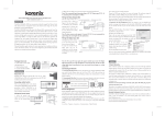
JetNet 3810G
JetNet 3810G / 3806G / 3710G
Quick Installation Guide v1.0
JetNet 3710G
LED per unit
LED per port
LED per unit
Power On/off x1 (Green on/off)
Link/Activity x10 (Green on/ blinking)
Power On/off x1 (Green on/off)
Link/Activity x10 (Green on/ blinking)
Alarm enable/ disable x1 (Red on/off) 10/100-TX Full Duplex/ Collision x8
(Yellow on/ blinking)
PoE LED x8 (Green on/off)
10/100/1000-TX Speed x2
Alarm enable/ disable x1 (Red on/off) 10/100-TX Full Duplex/ Collision x8
PoE LED x8 (Green on/off)
Package List
(Yellow on/ blinking)
10/100/1000-TX Speed x2
JetNet device
Attached 4-pin power terminal block
LED per port
(Yellow blinking)
(Yellow blinking)
ME outline
ME outline
Quick installation guide
1 Connect the power line
2
CD-ROM User’s Manual
1 Connect the power line
2
from the power supply
from the power supply
2 Indicators: Power on
2 Indicators: Power on
Overview
Interface
10/100 Base-TX
10/100/1000 Base-TX
PoE Injector
PoE Wiring Pins
Power Boost
JetNet 3810G
JetNet 3806G
JetNet 3710G
8
2
Port 1~8
4,5,7,8
12~24V Boost
4
2
Port 1~4
4,5,7,8
12~24V Boost
8
2
Port 1~8
4,5,7,8
(green on)
(green on)
Dimension (mm):
Dimension (mm):
149(H) x 131(W) x 66(D)
149(H) x 131(W) x 66(D)
Weight: 1.05kg
Operating temperature:
1
Weight: 1.05kg
Operating temperature:
1
-25~60OC
PIN assignment—Power connector
DIN rail Mount
The aluminum DIN rail attachment on the back of
Pin
JetNet Device is used to snap into the DIN rail plate
Power supply:
Single input 12~24V DC,
2 1
Power Signal
1
VCC
2
GND
boosting to 48V DC for PoE
Power consumption:
95W (incl. PoE), 30W
Note: For detail Power information,
-25~70OC
PIN assignment—Power connector
Power supply:
Single input 48V DC for PoE
2 1
Power consumption:
Pin
Power Signal
1
VCC
Note: For detail Power information,
2
GND
Please refer to User’s Manual
95W (incl. PoE), 30W
Please refer to User’s Manual
JetNet 3806G
Grounding JetNet
Connecting grounding screw to the earth ground will
LED per unit
ensure safety and reduce the interference of noise.
Wiring the Relay Output
Earth Ground
The relay output contacts are in
Alarm System
LED per port
Power On/off x1 (Green on/off)
Link/Activity x10 (Green on/ blinking)
Alarm enable/ disable x1 (Red on/off) 10/100-TX Full Duplex/ Collision x4
(Yellow on/ blinking)
PoE LED x4 (Green on/off)
10/100/1000-TX Speed x2
(Yellow blinking)
the Left of the terminal block
connector. By inserting the wires
Extra Power
System
ME outline
1 Connect the power line
2
and settings the DIP switch of
from the power supply
the respective alarm function to
2 Indicators: Power on
“ON”, relay output alarm will
(green on)
detect port or power fault, and
Dimension (mm):
form a short circuit.
149(H) x 131(W) x 66(D)
Weight: 1.05kg
Operating temperature:
1
Dip Switch Setting
-25~60OC
DIP Switches to configure Port Link Fail Alarm for GbE & PoE port
Pin No. #
1
2
Pin No. #
3
4
5
6
7
8
9
10
GbE port
2
1
PoE port
1
2
3
4
5
6
7
8
PIN assignment—Power connector
Single input 12~24V DC,
2 1
Note: The Pin No. of JetNet 3806G only DIP1~6
Default: off
Power supply:
Pin
Power Signal
1
VCC
2
GND
boosting to 48V DC for PoE
Power consumption:
80W (incl. PoE), 25W
Note: For detail Power information,
Please refer to User’s Manual
Korenix Technology Co., Ltd.
Tel:+886-2-89111000
Fax:+886-2-29123328
Business service:[email protected]
Customer service:[email protected]
CPQ000N3810000


