Transcript
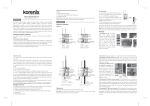
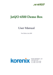
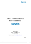
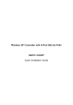
Overview JetNet 5310G Quick Installation Guide v1.0 3. Wiring the Digital Input (DI) 2. Preparation for Web management: The Digital Input (D.I.) contacts are in the Before you attempt to use the embedded bottom side of the device as shown in web interface to manage switch operation, below figure. It accepts one external DC verify that JetNet Switch is properly Korenix JetNet 5310G, the revolutionary DIN Rail type industrial Gigabit managed type signal input and can be configured to Power over Ethernet Switch is designed with 8 10/100TX PoE injector ports and 2 send alert message through Ethernet on this network can access the switch via Gigabit RJ-45 / SFP combo ports for highly critical PoE applications such as real when the signal is changed. The signal the web browser. time IP video surveillance, WiMAX systems and Wireless APs. All of the 8 ports of may trigger and generated by external Launch the web browser (Internet Explorer the switch are compliant with both IEEE 802.3af PoE and IEEE 802.3at high power power switch, like as door open trigger switch for control cabinet. or Mozilla Firefox) on the PC. PoE standards and can deliver up to 15.4W and 30W power per port to enable the Note: the DI accepts DC type signal and supports isolated input circuit with Digital Type http://JetNet Managed Switch_IP_Address (The default IP address is high-power requiring devices, such as Wireless APs, PTZ and dome network High Level input DC 11V~30V and Digital Low Level input DC 0V~10V. 192.168.10.1.), then press Enter. The login screen will appear next. cameras, etc. 4. Connecting the Surge /Lighting protection Type in the user name and password and click “OK” button. The welcome page of 1.1 Packing List Checking There is one screw fixed on the rear side for the Web-Based management interface will appear then. The default user name and JetNet 5310G lighting /surge protect; tighten and wiring to password is admin/admin. DIN Rail installation clip (tighten on the rear panel) chassis grounding to obtain better surge/ lighting At the left column of the web DB-9 to RJ-45 console cable immunity. But, do remember remove the surge management interface are the software CD User Manual grounding screw before insulation/Hi-pot testing. features, where ring column will list the Hardware Installation If does not, the protectors may damage during available settings. the testing. For more operating instructions, please Note: 1. Ensure the Surge/Lighting is well connecting with Chassis Grounding refer to the User’s manual of JetNet 2. Remove the Surge /Lighting Screw, before perform Insulation / Hi-pot Testing. Managed Switch included in the packing 1. Powering of the system The Power input port is located at the bottom side and provides 2 power input ports. The power input port support polarity reverse protection; the Switch won’t start if wrong polarity applied. The wiring architecture please refers to below figure. ! V- V+ installed on your network and that every PC Never install or work on/with the equipment or the cabling during or downloadable from the Korenix the period of its lightning activity. Website – www.korenix.com. Wiring the Power Inputs & Earth Grounding 5. Mounting the Switch onto the DIN Rail Korenix Customer Service 1.1 Insert the positive and negative wires into the V+ and V- contact on the The DIN Rail clip already tightens on the rear KoreCARE is Korenix Technology’s global service center, where our professional terminal block connector. side panel and supports EN50022 Std. DIN Rail. staffs are ready to answer your questions at any time. 1.2 Connect the Chassis Grounding to Earth Ground system to obtain Device Management Korenix global service center’s e-mail is [email protected] electromagnetic immunity to resist lighting, electro static discharge and electric fast transient. JetNet 5310G Industrial Managed PoE Switch provides both in-band and out-band configuration 1.3 Tighten the wire-clamp screws to methods. You can configure the switch via the prevent the power wires from being RS-232 console with the attached console cable. loosened. Notes: To use the UL Listed LPS Power supply with output Rating 46~57V Vdc, minimum 2A currents. Here, we recommended use DC 48V as the operating voltage. 2. Wiring the Relay Output (DO) The relay output contacts are in the bottom side as shown on below figure. The relay output (DO) is controlled by the pre-defined operating rules. To activate relay output function, please 1. Preparation for console management: Attach the RS-232 DB9 connector to your PC’s COM port. Connect the RJ-45 connector to the console port of the JetNet Patent No. (Taiwan): Granted Invention: I 356616 Granted Invention: I 346480 Granted Invention: I 344766 Granted Invention: I 321415 Granted Invention: I 313547 Utility Model: M 339840 Utility Model: M 339841 Switch. Go to Start -> Program -> Accessories -> Communication -> Hyper Terminal Give a name to the new console connection. Choose the COM name and select the correct serial settings. The serial port settings of JetNet Switch are as below: 9600bps, No parity check, 8 Data bits, 1 stop bit After connected, you will see the Switch login request. Type the username and password and then you can login. The default username is “admin”, password is “admin”. Follow the manual to configure the software features. Korenix Technology Co., Ltd. Tel:+886-2-89111000 refer to the CD User’s Manual for more Fax:+886-2-29123328 Relay Output management information. Business service:[email protected] Note: The relay contact only supports 0.5 A current, DC 24V. It is not recommended Customer service:[email protected] to apply voltage and current higher than the specifications. CPQ000N5310000 Ѯᢊடց ี݂ I ี݂ I ี݂ I 356616!ဴ 346480 ဴ 344766 ဴ ี݂ I 321415 ဴ ี݂ I 313547 ဴ! ཱི M 339840 ဴ ཱི M 339841 ဴ