1
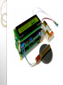
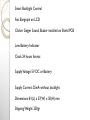
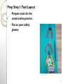
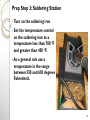
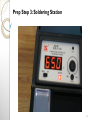
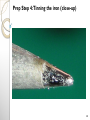
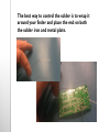
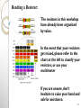
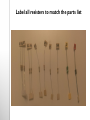
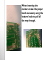
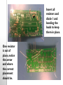
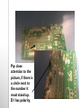
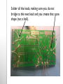
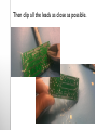
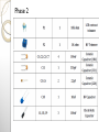
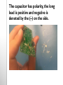
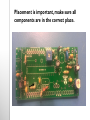
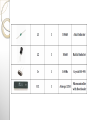
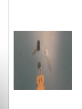
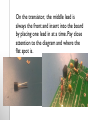
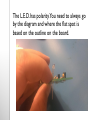
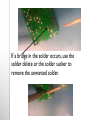
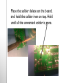
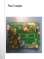
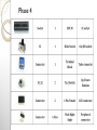
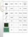
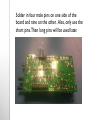
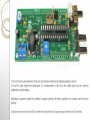
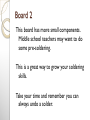
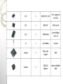
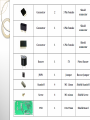
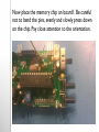
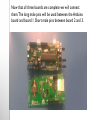
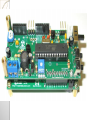
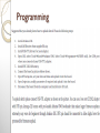
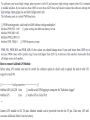
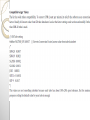
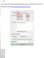
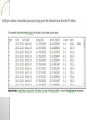
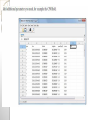
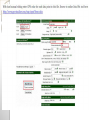
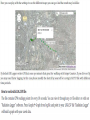
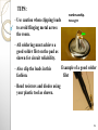
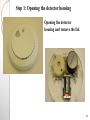
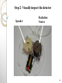
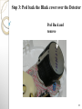
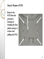
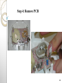
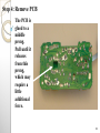
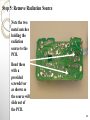
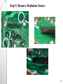
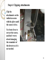
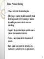
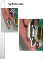
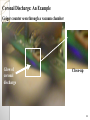
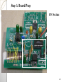
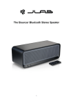
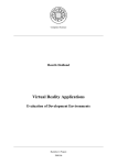
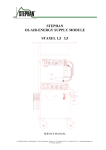
The Geiger Counter Board
Geiger Counter
Background
Arduino IDE Geiger Counter DIY
Kit Radiation Logger with LCD and
Free Monitoring Software with SD
Shield w/ GM Tube
2
Radiation: Overview
- Radiation is generally
viewed as harmful to space
payloads.
- While some projects
purposely expose parts to
the saturated Van Allen
belts to investigate the
effects of high energy
particles, some projects
must avoid harmful doses at
all costs.
- Sparse data has been
collected from suborbital
airspace.
- This payload will allow for a
large collection of data sets.
Van Allen Belts:
www.nasa.gov
3
Radiation: Effects
- Single event
phenomenon (SEP),
burnouts and bit
flips can cause
damage to solid
state devices aboard
a space payload.
- An understanding of
dose levels is ideal
to plan a mission to
sub-orbital altitudes,
especially with
sensitive optics or
microprocessors.
SEP diagram: www.aero.org/
4
Radiation: Effects
- There are three types of
radioactive emissions:
- Alpha - the least penetrating
form of radiation, can be
stopped with a piece of paper
or a few inches of air.
Particle
- Beta-rays are more penetrating
comparison:
than alpha-rays
www.freedomforfis
- Gamma-rays are the most
penetrating form of radiation. sion.org.uk
Often produced in conjunction
with alpha or beta-rays, they
can penetrate several inches of
steel or hundreds of feet in air.
5
Radiation: A General Trend
Radiation levels
roughly double
every 5000 feet in
altitude, so at sea
level dosage will
be roughly ½ the
level observed in
Denver, Colorado.
6
Radiation: A General Trend
- However, radiation levels do depend on the level
of cosmic radiation, effective shielding, and any
ground or building materials containing
radioactive materials.
- In general, at sea level; you should see 12-14
counts per minute.
- This device has resolution to 2 μs. Which
indicates it cannot detect particle events closer
than 2 μs to each other.
7
Radiation: A General Trend
8
Radiation: Dosage and Limits
-Max dose for occupational
workers (Nuclear Power) 5
Rem/yr (max exposure to retina).
[2]
Shielding can
drastically
reduce the
observed dose.
Be sure to wear
safety glasses
when handling
the material.
-Max dose recommended for the
general public 100 mRem from a
high energy source over a short
time frame. [2]
-An average American receives
360 mRem/yr from natural
background and manmade
sources. [2]
[2]
http://www.jlab.org/div_dept/train/
rad_guide
9
Radiation: Comparisons
-A typical radiation dose from a chest x-ray is about
10 mRem per x-ray (Gamma exposure) [2]
-Consumer products contain radiation, such as:
smoke detectors, and lantern mantles.This dose is
relatively small as compared to other naturally
occurring sources of radiation and averages 10
mRem in a year (Alpha exposure). [2]
20th Century Fox
©
10
- Generally, 75 counts per
minute (CPM) is
equivalent to 1 mRem/hr.
Radiation: Conversions
- Therefore, 4500 CPM is
roughly equivalent to 1
mRem
- A source from a smoke
detector makes up 2.8%
of the yearly average
expected dose, which is
.027 mRem/day or .0012
mRem/hr
- These numbers shouldn’t
alarm you, an average
person receives 1 mRem
per day.
20th Century Fox ©
11
Let’s Start
Building!
12
What Are We Building ?
- Basic Geiger Counter
- Audio and Visual Cues
for Radiation
Detection
- Can detect Alpha,
Beta, and Gamma
Radiation.
13
Quick Overview
Arduino IDE DIY Geiger Kit ver. 1.01 with SD Logger
Shield for micro SD card
This is open source code Geiger SD Logger project based
on Arduino IDE. The kit includes main board with 16x2
LCD and SD Logger Shield. We supply electrical circuit
and Arduino source files for this project.
SD Shield has RTC circuit (real time clock), 3.3V level
shifter for SD card, Buzzer and micro SD socket. Support
connection of Adafruit GPS module or UART logging
through RX TX pins. Files on SD card contains CPM
readings for each data point, your local date and time,
nmea geographical data and total absorbed dose. 400V
high voltage for GM Tube produced with PWM.
Microcontroller program correct high voltage if battery
capacity is too low. The kit makes clicker sound similar to
a “classic” Geiger counter sound.
Technical specifications:
Geiger Tube Compatibility: GM Tubes with anode voltage 350-550V
Arduino IDE compatible, minimum hardware for maximum performance
LCD 16x2 HD44780
Two tact buttons for controlling the software
Moving Average calculating algorithm
Represent dose in uSv/h or uRn/h units
UART logging with "Radiation Logger", require USB-TTL dongle
Adafruit GPS module support
SD Shield Board with RTC
Absorbed dose, CPM, NMEA logging
Smart Backlight Control
Fast Bargraph on LCD
Clicker Geiger Sound, Buzzer installed on Shield PCB
Low Battery Indicator
Clock 24 hours format
Supply Voltage: 5V DC or Battery
Supply Current: 25mA without backlight
Dimensions: 81(L) x 37(W) x 50(H) mm
Shipping Weight: 250gr
Radiation SD Logger based on Atmega-328 and programmed
with Arduino IDE. SD Shield has SMT parts that require
good soldering skills! Atmega microcontroller comes with
Arduino IDE bootloader, but you need to upload supplied
sketches by yourself.
The main benefit of this kit is SD Logger Shield. It support
micro SD Cards with capacity 2Gb-8GB. Radiation data
stored with 3 files. Each time you starting the counter, it
will create a new log files and the older files stay safe on
card. Up to 100 files can be created before you need to
clear SD memory. LOG.CSV store CPM readings for each
data point. The file can be opened with our "Radiation
Logger" Windows application for building graph or with any
csv editor. LOG.TXT store local date and time, CPM,
aborbed dose accumulated since last minute and battery
voltage. If GPS module connected, LOG.TXT will also store
NMEA geographical data. DOSE.TXT file keeps only total
lifetime absorbed dose. User manual describes an example
how you can export nmea data to google map and add CPM
readings to the map.
The software and hardware where designed to produce
tube high voltage with PWM technology. No additional
IC's required, everything is controlled with software.
By default it programmed to 400V-420V and you can
make fine adjust through software calibration from
350V to 480V. If required, the kit can be adjusted for
500V-550V. For higher voltage it possible to make 600V
hardware mode with voltage multiplier.
When using batteries for powering the counter, you do
not have to worry about tube voltage drops because of
low battery, microcontroller will correct high voltage if
your battery capacity is half or low. Battery indicator
on LCD will work only with Ni-MH type.
The kit compatible with many popular Geiger tubes, such
as SBM-20, SBM-19, SI-29BG, SI-180G, SBT-9, SBT-11,
J305 and more 400V tubes. When it tuned to 500V you
can use LND-712, LND-7317 or similar.
Current radiation dose in uSv/h or uRn/h units represented on LCD with
CPM (counts per minute) readings.You can switch between LCD units with
pressing "down" button. If you press "up" button, it will shows clock for
several seconds, like a digital watches. RTC needs 3V backup battery
CR1220. This battery is included. PCB allows you to use CR2032 backup
battery for RTC with other low cost holder type.
Adafruit GPS module can be connected to RX TX pins and selected through
sketch settings during firmware uploading. If no GPS presented, you can use
RX TX pins for UART logging. CPM value logged through UART to our
"Radiation Logger" Windows program.When connected to computer, the
kit can be used as nuclear radiation monitoring station for local
logs, radmon or xively. It possible to separate SD Shield from the Main
Board if kit used only for UART logging.
Fast bargraph on LCD for search mode represent CPS (count per second)
measurement. The scale controlled through arduino sketch.
The counter has smart LCD backlight controlling for saving battery. Backlight
will light on when CPM value reach presetted alert threshold or if you
press any button. Alert BL pin is combined with LCD backlight and can be
connected to additional alert led or drive relay module.
The kit produce clicker sound beeps similar to "classic" Geiger Counter
sound.You can mute buzzer with jumper removed. If radiation level is high,
the kit inform you with additional sound indication.
Prep Step 1: Tool Layout
- Prepare tools for the
construction process.
- Put on your safety
glasses.
23
Prep Step 2: Grounding
- Put on a static strap to remain
grounded. Also make sure the
strap is tight across your wrist.
- This will protect any parts from
electro-static discharge (ESD)
and its harmful effects.
24
Prep Step 3: Soldering Station
- Turn on the soldering iron
- Set the temperature control
on the soldering iron to a
temperature less than 700 °F
and greater than 450 °F.
- As a general rule use a
temperature in the range
between 550 and 650 degrees
Fahrenheit.
25
Prep Step 3: Soldering Station
26
Prep Step 4:Tinning the iron
- Tin the tip of the soldering
iron by melting an inch or
so of solder on the tip.
- The iron will now look
shiny on the tip.
- Then wipe any excess
solder on the golden
sponge.
- Now place the iron back
into the holder. Tinning
your soldering iron in this
manner will aid in future
soldering.
27
Prep Step 4:Tinning the iron (close-up)
28
The best way to control the solder is to wrap it
around your finder and place the end on both
the solder iron and metal plate.
Verify Kit Contents
- Open your kits and verify the
contents with the provided list
and visual layout.
- Find the Geiger Mueller (GM)
Tube and set it aside in a safe
place.
- You won’t need the GM Tube
until the last few steps.
GM TUBE
30
Reading a Resistor:
The resistors in this workshop
have already been organized
by value.
In the event that your resistors
get mixed, please refer to the
chart at the left to classify your
resistors, or use your
multimeter
If you are unsure, don’t
hesitate to raise your hand and
ask for assistance.
31
Put on Eye Protection Now
Board 1
Phase 1
Label all resisters to match the parts list
When inserting the
resisters make the proper
bends necessary using the
bottom leads to pull all
the way through.
Insert all
resisters and
diode 1 and
bending the
leads to keep
them in place.
One resistor
is out of
place, notice
the arrow
and where
the correct
placement
should be.
Pay close
attention to the
picture, if there is
a circle next to
the number it
must stand up.
D1 has polarity.
Solder all the leads, making sure you do not
bridge to the next lead and you create that cone
shape (not a ball).
Then clip all the leads as close as possible.
Phase 2
The capacitor has polarity, the long
lead is positive and negative is
denoted by the (–) on the side.
Placement is important, make sure all
components are in the correct place.
Phase 3
,T3
On the transistor, the middle lead is
always the front and insert into the board
by placing one lead in at a time. Pay close
attention to the diagram and where the
flat spot is.
The L.E.D. has polarity.You need to always go
by the diagram and where the flat spot is
based on the outline on the board.
If a bridge in the solder occurs, use the
solder delete or the solder sucker to
remove the unwanted solder.
Place the solder delete on the board,
and hold the solder iron on top. Hold
until all the unwanted solder is gone.
Phase 3 complete
Phase 4
Carefully place
the socket into
the board, paying
close attention
to the diagram
and where the
indicator is.
Put the six pin female connectors in. Break
the right angle connectors in half and place
on either side of the female connector.
Solder in four male pins on one side of the
board and nine on the other. Also, only use the
short pins. Then long pins will be used later.
Board 2
This board has more small components.
Middle school teachers may want to do
some pre-soldering.
This is a great way to grow your soldering
skills.
Take your time and remember you can
always undo a solder.
Label all components before beginning. This will
make it easy to find the correct placement on
the board.
Easiest order:
1st C1 and Cr
2nd SD Socket
(there are tabs to help align)
3rd C2, C3, C5
4th R1, R2, R3
5th T1, IC1, IC2, IC3
6th C4
7th Female connectors,
buzzer, batter holder
Cr will need to be soldered to the metallic tab.
Pay close attention to not bride the SD
socket leads. Very close together and a
magnifying glass would be advised.
Use the order given as some components block
the others. They are small but as long as you
don’t bridge the solder it is straight forward.
Now place the memory chip on board1. Be careful
not to bend the pins, evenly and slowly press down
on the chip. Pay close attention to the orientation.
Now that all three boards are complete we will connect
them. The long male pins will be used between the Arduino
board and board 1. Short male pins between board 2 and 3.
Programming
TIPS:
- Make sure the static strap is tight
across your wrist at all times.
- DO NOT linger on parts with the
soldering iron.
- As a general rule use a 5 second
linger time with a 10-20 second cool
time for parts.
- Mount and solder components
flush to the board unless otherwise
stated.
92
TIPS:
- Use caution when clipping leads
to avoid flinging metal across
the room.
workmanship.
nasa.gov
- All soldering must achieve a
good solder filet on the pad as
shown for circuit reliability.
- Also clip the leads in this
fashion.
Example of a good solder
filet
- Bend resistors and diodes using
your plastic tool as shown.
93
Let’s Begin!
94
Step 1: Opening the detector housing
Opening the detector
housing and remove the lid.
95
Step 2: Visually inspect the detector
Speaker
Radiation
Source
96
Step 3: Peel back the Black cover over the Detector
Peel Back and
remove
97
Step 3: Peel back the Black cover over the Detector
98
Step 4: Remove PCB
Remove the
PCB from the
protective
housing by
bending the four
plastic prongs to
release and
pulling the PCB.
99
Step 4: Remove PCB
100
Step 4: Remove PCB
The PCB is
glued to a
middle
prong.
Pull until it
releases
from this
prong,
which may
require a
little
additional
force.
101
Step 5: Remove Radiation Source
Note the two
metal notches
holding the
radiation
source to the
PCB.
Bend these
with a
provided
screwdriver
as shown so
the source will
slide out of
the PCB.
102
Step 5: Remove Radiation Source
103
Step 6: Clipping attachments
Clip the
attachments on the
radiation source
with the pliers until
the source is free.
Use brute force to
extract the source,
and don’t worry
about damaging
the remainder of
the detector as it is
not needed.
104
Step 6: Clipping attachments
105
Step 6: Clipping attachments
106
Step 6: Clipping attachments
107
Step 7: The source is ready
108
Final
Product:
Testing
109
Final Product Testing
- Attach power to the circuit again.
- The Geiger counter should randomly blink
detecting usually 12-14 counts per minute
depending on sources in the area and
shielding.
- Acquire the provided alpha particle source
(taken from a smoke detector).
- Notice a large jump in the frequency of
counts.
- Each count represents the detection of a
radioactive particle by the Geiger counter.
110
Final Product Testing
111
Coronal
Discharge
112
Coronal Discharge: An Overview
- Coronal discharge occurs in low pressure
environments with high voltages present.
- The air around a high potential (high
voltage) will become a conductor and emit a
bluish glow (plasma).
- This plasma will cause adverse effects for
the component as well as neighboring parts.
- The plasma is a bluish-purple and is visible
under normal lighting. (see images)
113
Coronal Discharge: An Example
RockOn! Geiger counter seen through a vacuum chamber.
Area of
interest
near back
of D4-D6
114
Coronal Discharge: An Example
Geiger counter seen through a vacuum chamber
Glow of
coronal
discharge
Close-up
115
Coronal Discharge: The solution
- Coronal discharge is detrimental to parts.
- Dangerous to other payloads on the rocket.
- To mitigate these risks, we will add conformal coating to
the board to prevent coronal discharge.
- **Note: We will be in a pressurized environment on this
flight so this is not necessary, but is a good practice
especially with space applications.
116
Conformal Coating
117
Step 1: Board Prep
- Take the board to a well
ventilated area (we will
be outside).
- Put on safety glasses and
rubber gloves.
- Place the board face up
on the prepared
protected surface.
- Shake the bottle lightly
and open it.
- MAKE SURE there is no
power on the board.
118
Step 1: Board Prep
HV Section
119
Step 2: Begin Coating
- Dip the brush in and begin
application coating the
entire top side of the board
with an even layer.
- Re-dipping the brush every
2-3 strokes is
recommended.
- The board should look
glossy under lighting where
coating has been applied.
- If any safety concerns occur
consult the MSDS provided.
120
Step 3: Detail Coating (chips in sockets)
- Coat the chips as well as long as
they are secured in their sockets.
121
Step 3: Detail Coating (underneath components)
Apply
underneath
closely
oriented
parts like
diodes,
capacitors,
and
resistors in
this
manner.
122
Step 4: Detail Coating (between components)
Apply
between
closely
oriented
parts
Use
smooth
strokes
(about 3
per dip)
123
Step 5: Backside Coating
- Flip the board
over using
minimal
contact with
the currently
curing coating.
- Coat the entire
backside as
desired using
the same 3
stroke per dip
rule.
124
Step 5: Backside Coating
Apply across
the whole
board, make
sure the whole
PCB is coated
thoroughly.
Note glossy
look of
coated
board.
125
Step 6: Touch-ups
- Visually inspect the board to
ensure it is coated thoroughly.
HV Section
- Make any touch-ups as
necessary, ensuring there are
no bubbles underneath parts.
- You may add additional
coating to the HV section if
you desire, but one coat is
enough to do the job.
126
Step 7: Drying and Clamping
- Flip the
board over
and attach
to helping
hands
where
shown.
- This area is
not HV and
won’t affect
the cure if
clamped
here
127
Step 7: Drying and Clamping
- Allow the board to cure in a controlled
environment for 24 hrs to achieve a full cure.
- Tack free cure is about 10 min. The coating wont
stick to your hand as readily after this stage.
- Handling cure is about 4-6 hrs depending on the
humidity.
- Cure time can be decreased by using a convection
heater at low heat (100 °F) and low humidity.
128