1
Brief introduction
Software of the model TOP 48 operates under windows 98 SE/ME/2000.
For windows98SE/ME/2000:
1.Take off TOP 48 (Do not connnecting with TOP 48);
2.Run “setup.exe ” from disk,and continue;
3.Finally press the button comfirm and start the computer again.
4.Aftor starting the windows. Use the wire to connect with TOP48.The flat head
of the wire connects to the USB interface of the PC computer.the square head to
TOP48.
5. After the redlight
is on ,run “Start/programme/TOP48/TOP48.exe
” .Wait for
about five seconds,if the green LED light,every thing OK.
For windows XP:
As the complexity of XP copy and the speciality of USB control,The procedune
of
installation
throngh
a few
isn’t
times
smooth
can
you
supports xp, some of users can
like
the
sulleed.
WINDOWS98
AS
Cupress
SE/ME/2000.Sometimes.only
does
not
confirm
that
it
not operate wnder“XP”. Most of them operate very
well.
1.Remove TOP48
2.Operate
programmer(Do not connecting with TOP48).
the
“setup.exe ”on
the
compact
dis
and.finish
auoding
to
the
instraction.
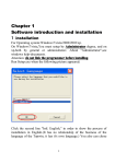
3.After starting
windows xp again connect the TOP48 to the USB ,the red LED
light. Computer will found new hardware device and show message as follows:
Xxxxxxxxxxxx
xxxxxxxxxxxxxxxxx …
Cypress EZUSB(2131Q/2131S/2135S)EEPROM
missing
“EEPROM missing ” is a common information.
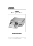
4.If finding the USB device drive file(.inf &.sys),display as follows.
Xxxxxxxxxxxxxxxxxxxxxxxxx
Xxxxxxxxxxxxxxxxx
Cypress EZUSB(2131Q/2131S/2135S)EEPROM
missing
xxxxxxxxxxx(I)
Xxxxxxxxxxxx(S)
Choose (I),and press the next step(N) to autoinstalling software.
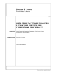
5.Now you can see message as follows:
xxxxxxxxxxxxxxxxx
Cypress EZUSB Simple Device
xxxxxxxxxxx
Xxxxxxxxxxxx
press the next step(N) to continue;
6.“Finding new hardwane guide ”The talk frame shows. “Finishing finding the new
hendware guide ”pness “end”and installation is over.
7. start the WindowXP again.
8.Combine
TOP48 with usb connective
mouth.Run
TOP48.exe.After
TOP main window
wait of about 5 secod, green LED is on. Every thing is OK,you may write and read
the device normally.Take
your attention!If the green LED light is out.you can’t
continue readdin g and writing, or show “Read USB bad!”
9.If you can ’t open the equipment it shows the driving grograum fails. Now need
reinstall from step1 to step8.
Hard ware Installation.
1.The USB interface may insevt or pull with electricity first start the computer
and then connect with TOP48.
2.connect the flat head of the wire to the interface of USB,the square head of
it to the outlet in the side of TOP48(each end of the wire is different,you must
distingnish
one from another )The power LED(red) is on, Now the computer
has
connected with the programm of TOP48.After about five seconds later.The working
LED of TOP48 “READY ”(green)is on.The computer is ready to operate now.
3.Run “Seting/system/ ”On the main menu, Click “Power status ” to display power
status.If show between 5 lever to 10 lever, power is OK.If the lever less than
5,you
may
connect
it
to
the
preparing
stable
powersupply(5V/2A).If
beyond
grade10 .the USB interfa ce can ’t insert or pall with electrily you must connect
with the prograncmer first them the computer works well or affect the protection
electric circuit of the coputer,start the computer again.
4.Offline
operation,under
operate the softwere of
not
connecting
with
TOP48,The
computer
may
also
TOP48 when the intraction that can’s open the equipment
appears. Press the botton “OK”for offline operation.
Main Window.
Main window of TOP48 as follows
Most of operations
about
TOP48 can be carried
out in the main menu.
Some
ordinary operation.
Can be operated by directly touching “fast key ”.
It can come up the same effete as the menu operating does. Even more quickly and
convenient.
Operating concerning
the needing and writing is carried out in the
related talk frame after choosing the model.
Notice
The file window displays the data being written into the component.
Chapter 1 Software operation
ONE.
1
File operation and Edition.
File operation.
Choose “file ” in the main menu, POPUP as follows:
The file menu contains the memory operation of file.
It is divided into the binary system and the hexadecimal format
The choice is finished in the format talk after choosing the file name.
The data is loaded into the buffer area after confirming the file format. And
start address.
Display as follows.
2
Amending file data.
You can move the word. By mouse or touch if need to amend the data, after
loading the file into the file window. Directly touch the key to enter the data.
But it must be twoposition hexadecimal.
File data window as follows:
3
Positioning data start address:
If there are large amounts of data .It is hard to find the
Data you want. You may touch the “Enter key”. The window
Will move to the address.
4
Edit and Amend the menu.
5
Fill in the data.
Choose mean, “amend and fill in data ” popup talk frame.
Enter
the
address
scope
and
the
data
that
is
filled
up.
Then
touch
the
“Confirm ” key.
6
Searching
The “searching ” order is used to search the pointed hexadecimal
number at
the data window. Only input two Characters, after carrying out the order.
POPup talk frame as follows:
Touch “search for the next ” and begin to search.
Continue to search again by touching “search for the next ”.
7
Replace the character.
The order is used to replace the text character
after carrying
out the
order. popup substituting talk frame as
follows
Enter the text character substituted
in the “search aim” frame also paste
on the clip board.
First touch “search the next” to find position of the character substituted
Touch the “Replace ” key again.
Be careful! First you have to touch the “search the next ” key for the second
time, touch the “replacement ” key again.
8
Expand or Contract the file buffer zone.
The area of the file buffer zone is usually as large as the file. If you
add the data, you must first expand the largest address of buffer area,
Choose the menu “amend and expend or contract the file buffer area” popup
talk frame: Input the largest address or the right of the end address. Then
touch the “Yes” key.
9
POPUP format menu.
Filling up and expending or contracting file buffer area
may be carried out by popup menu.
Singletouch the right key of mouse on the file window
and popup the following menu.
10 Edition Key
Page up
Home
Page down
End
Two. Choose model.
1
Choose the menu “operate and choice model ”popup window as follows.
2
Choose the memory or computer on slice in the “category ” frame or other
category.
3
Choose the producer in the “manufacturer ” list frame.
Example: Choose “Atmel ”.
4
Choose the model in the “Component model ” list frame.
For example, choose “89c51 ”.
5
Touch the “conform ” to enter the reading and writing operation.
6
After choosing the category, also touch the “Testing
Factory code ” to get the twoword code .
The firstword standards for the manufactory . The secondword
Standards for the type.
Chapter 2
ONE.
1
Read and Write EPROM, EEPROM.
Ordinary procedure .
Connect the TOP48 well, Then Connect 9V. 400MA direct current into the right
outlet then lamp lights.
2
Operate “TOP48 exe”
3
Choose the “file ” in the main menu and load the data in the
File buffer area
4
Insert the chip into the outlet and lock tightly
5
Choose model, popup operation window after confirming.
reading and writing operation is carried out.
TWO. Read and write operation.
All sorts of model operation are almost the same.
Take an example for the 29c010 as follows:
1
Window.
Choose the “operation\read and write component ”. popup
the operation window.
2
The file start address.
Generally, begin with the zero address and enter the data.
but also change
address. enter the data into any possible
beginning
address
Enter the HEX number.
The biggest number may be the six –position. the biggest address, 8M, default
“0”.
3
The component start address.
Insert the data into the possible start address. operating
is the same with 1 default zero.
4
The data length.
HEX system address length.
5
Write the component.
Before writing the component, pay attention to the
Component model. Don’t make a mistake about the programmer voltage. or destroy
the
component
or
equipment
after
conforming
all
devices
is
right.
Put
the
component programming into the component outlet and lock the slab.
After writing, the programmer autochecks, if any errors.
the wrong address and content will be shown at the window, during the writing
touch the “Ctrl” and stop operating.
6
Read the component
Insert the content of the chip into the buffer area
7
Erase
Erase the whose content, then display the “FF”.
As long as the electric erase may use the order,
EPROM should be erased in ultraviolet radiation erasing.
8
Blank
Before enter the component, Check if empty,
Every word of the empty is “FF” ( HEX system )
If
finding
the
blank
word
daring
the
searching
the
wrong
address
and
content will be shown at the window and stop searching
Check
the all address
space
of EPROM
when searching
nothing to do with the beginning address and length set up.
the blank
.It has
9
Verify
In order to be same that the data writing into the component
is right. Compare the content of the component with the file.
If different the address and content of this word will be shown at the window.
Read operation includes the comparison not reoperation.
10
Protect
Many EEPROM and FLASTI came protection function.
Protected the component only read not write
Only after protecting can you rewrite.
11 Unprotection.
It is contrary with the protection.
12 Read ID
Get the twoword code the firstword
Standards for the manufacturer and the secondword the
Model.
13 Write speed
The programming speed from the different factory product
is almost different even from the product of the same factory.
Its
different
model
has
the
different
programming
speed.
Generally
the
standard speed is sep up.
Check if it is blank before writing the component.
Every word of the blank is all “FF”(HEX system)
Or.
It isn’t allowed to enter the new content.
ultraviolet lamp may be used to check after if not.. the
component is spoiled.
If finding wonblank word. When checking.
The
wrong
checking
address
and content
will
be shown
at the window
port
and stop
Chapter 3 Read and write MCU
ONE
1
Ordinary steps.
Connect
TOP48 well, Insert the random 9V. direct
current into the right outlet the power lamp lights.
2
Operate “TOP48, exe” ;
3
Choose the file in the main menu and load the data in the file buffer area.
4
Insert the chip into the outlet and lock tightly.
5
Choose model. popup operation window.
Reading and writing operation is carried out.
TWO. Read and write operation.
All sorts of model operation are almost the same . Take
An example for the 89c51 as follows.
1
Window
Choose the “operation\read and write component ”
POPUP the operation window.
2
Write the component,Especially
pay attention to the component model, before
writing the component. After no mistake is confirmed in all device. Put the
programming component on the outlet lock slat.
The programming is autochecked after writing if any errors,
the wrong address and content will be shown at the window.
3
Read the component.
Read the content of the chip into the file buffer area.
4
Erase
Erasing the whole content it will be shown “FF”, Only
by the electric erasing can this order be used. EPPOM needs
ultraviolet radiation erasing.
5
Blank
Before enter the component. Check if empty. Every word
of the blank is “FF”.
(HEX system)
If finding the won blank, when searching the wrong address
and content will
be shown at the window and stop searching.
Check the all address space of ERROM when searching the
Blank. If has nothing to do with the start address and length set up.
6
Verify
In order to be sure that the data writing into the component
is right. compare the content of the component with file, If
different the address and content of this word will be shown at
the window.
Read operation includes the comparison not operate it again.
7
Protect
Don’t read after the programming protection.
In order to protect
the producers
benefits
only after erasing
write again.
8
M.F.G.
Get the twoword cold, the firstword standards for the
Factory, and the second, the model.
can it be
Chapter 4
1
Testing SRAM
Choose the menu order. “operate/choosing
model ” popup the talk frame as
follows:
Choose “Testing static RAM ” popup the following window.
2
Choose the model (by) with a mouse.
3
Touch the “fast test” or “alltest ” and begin to check.
Chapter
ONE
1
5 Read and Write serial port memory.
ordinary procedure
Connect the TOP48. Insert the 9V direct current into the right power outlet
the power lamp lights.
2
Operate “TOP48, exe”
3
Choose the “file” in the buffer area menu and load the data in the file
buffer area.
4
Insert the chip into the outlet and lock tightly.
5
Choose model, popup the operate window after confirming
Read and write operation of the component is carried out.
TWO.
Read and write operation.
Window:
Choose the operation\ read write Component:
in the main menu and pop
up the operate window.
1
Choose the writing speed.
The serial port memory, its “write speed ” is of great
Difference. if slow, no mistake is made , but it takes long
to write. if fast, you’d better choose the different speed
experiment, move over, the near data may overlap
to make a mistake. Generally. 220ms
2
Read the component
Only once read the data of the component into the file
by
buffer area then “Storage file” menu order preserves the data
in order to be used in the future
3
Write the component.
Write the data of the file window into the component.
You must prepare for the data at the file window in advance
Write into the component of this series by covering way .That
erase.
4
Comparing the data.
“Write ” operation contains comparison. usually you needn ’t
compare again but compare with file separately to confirm if
the file is the same with the data of the component.
is to say. Don’t
Chapter 6 Read and Write PLD
ONE.
ordinary procedure.
1. Connect “TOP48 ” well. Insert the 9v direct current connector into the right
power outlet then the instruction lamp light;
2. Operate on the main menu the “TOP48, exe”;
3. Choose
the “file
/transferring
the file into
the buffer
area /PLD
file
{JED} ” and load the data in the file buffer area;
4. Insert the chip into the outlet and lock tightly;
5. Choose the model, popup the operation window after
confirming then read and write the component.
TWO.
File format
All the PLD files take the “melting silk file ” in the shape of
JECED, its
expending name is “JED” choose the file in the main menu and transfer the file
into the buffer area /PLD File (JED) then load the data into the file buffer
area.
Shown as follows.
THREE
Read and write operation.
Window:
Choose the “operate\ read and write component ” on the main menu then
popup the operate window.
1
Read the component
Only once read the data of the component into the “File window ”.
2
Write the component
Write the data of the file window into the component, The
data of the file
window need be prepared in advance and only after the component must be blank
can it be written.
3
Compare the data.
“Writing ” operation includes comparison.
Generally, not comparing,
but it can be compared with the file separately. Be
sure that the file is the same with the data of the component.
4
Erase
Eraser
is used
to
erase
the
original
contents
constructing control field and flag field etc.
including
the
array
fuse
Chapter 7 Testing the common integrated Circuit.
Choose the “operate/ choice model ” on the main menu.
Choose the 7th item of the “category to test TTL/CMOS ”
Return to the testing window as follows.
1
Choose the type
Use the TOP to test thousands of types with the 74.45.40
series components. Every item corresponds with a bank file.
2
Typechoosing.
After conforming the family bank you can choose in the list
frame to test the certain type.
3
Testing
Testing the logic function of the component to judge whether
The component
is good or not. If good, the speaker rings down only once or
three times.
4
Autotest the type.
You can find out its type by this function if its type is unknown.
The component with the same logic function may have
several different types. They will be shown at the window.
5
The list for testing type.
74xxx
00
01
02
26
27
28
70
72
74
03
30
85
04
05
32
06
33
86
37
07
08
38
40
95
107 108
09 10
42
43
109
11
12
13
14
15
16
17
20
21
22
25
45
46
47
48
50
51
52
53
54
55
60
110
111
112
113
114
116
123
125
126
128
132
133
136
137
138
139
145
147
148
150
151
152
153
154
155
156
157
158
159
160
161
162
163
164
165
166
168
170
173
174
175
180
183
189
190
191
192
193
194
195
240
241
242
243
244
245
247
248
249
251
253
257
258
259
260
266
273
276
279
280
283
290
293
295
298
299
322
323
352
353
365
366
367
368
373
374
375
377
378
386
390
393
465
540
541
573
574
590
640
641
643
644
645
12
13
670
688
804
805
870
40xxx
00 01
02
06
07
08
09
25
26
27
28
29
30
32
33
35
38
40
41
42
43
44
48
49
50
54
55
56
60
63
66
67
68
69
70
71
72
73
75
76
77
78
81
93
94
95
96
97
99
101
175
192
193
10
11
102
103
14
15
105
16
106
17
108
18
19
109160
20
2122
23
24
51
52
53
82
85
86
161
162
163
174
109
160
161
162
194
45xxx
01 02
03
04
06 08
10
11
12
14 15
19 20
29
32
38
53
55
56
72
84
85
103
105
10 11
12
14
15
16
163
174
175
43
192
193
194
07
08
16 17
18
106
108
45xxx
01
53
02
55
03
56
04
05
72 84
06
85
17
18
19
20
29
32
38
43
TOP48 has the function of the “additional information ”, except the users
code file. The user may use it to keep a security for software or other parposes
Choose the “Seting/other ” on the main man, and enter the following window.
(1) “Increment ” page:
Operate the position of the addition information in the programme frame of the
“stast position ”. The position must he the space that the device doesn ’t finish
using generally, at the baclc of file, if the room is ouapied by the users files .
The additional information can ’t be writer again.
1. Set the start address in “star addr” frame;
2. Set the length of data in the “Length ” frame (Max 8 char);
3. Set a integer value in
“Data ” frame;
4. Choose the additionl quantity in the “increment ” frame, it is also integer
if the minas flay is addedup. It show “decnement ”.
5. Choose the “Enable ”.
(2) “Date ” page:
1. Set the start address in “star addr” frame;
2. Choose the Date and line allowed.
3. Set “Enable ”.
(3) “other ” page :
1.
Produeing
method in quantity. If admitted while reading and writing the
device,
press
the
“Auto” only
tightly
kegin
neading
once
and writing
whether
selftesting
device
is inserted
programme at once. Not pressing
the mouse
sartablefor a great deal of .
Press the “Auto ” and operate for one time, it will displ ay “OK”, please take
many the written device.
After
take many the device, display the “put the next
one —”. After the next is put well and all pins keep a good torch with them.
Auto recycle operation If it is over 5 seconds it will netine out the necycle.
2.
Testing the condition of the pin , of admitted a single tonch with each
cheek
whether
each
pin keeps a good tonch
with nepovt
immediately
and stop
operation.
3.
Qnichlytesting
Testing
the
careat
the electric
is
still
clecrease its sensibility.
carnemt
effectiue
,
evon if this choice is forbidden.
slow
down
the
calcite
speed
and
Notice:
1.
If you need to use the adapter you’d better buy the original product of
import (pin is slight) or purchase the product from our company the bad pin is
easy to damage the lock socket.
2.
If the electric current of USB is under grade 5 you should can ’t with
the stable poner (5V12A) if begond the grade 10 or equal to it. It can’t be
inserted and pulled with electricity you should conneet with programmer first.
3.
The adapter and loac socket are easy, to damage. The maintenance isn’t
guaranteed.
TOP48 series cparts ’:
1.
A main frame of TOP48.
2.
A stable power (5V12A).
3.
A universal adapter for SDP—UNIV —44(simple).
4.
An adapter for PLCC32, (simple).
5.
Standard wire(USB1.1)
6.
A user ’s Manual for Top48 programmer.
7.
A software disc
A ppendix:common reference for the universal.
Adapter:
1.
SPD—UNIV —44
PLCC44(P44)
2.
SPD—UNIV —44
SOP44(Q44)
3.
PLCC32
4.
SOP44
5.
SDP—UNIV —48
TSOP48
6.
SDP—UNTV —40
TSOP40
7. SOP—UNTV —i320
uBaA48