1
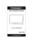
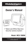
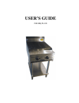
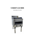
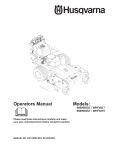
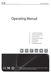
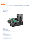
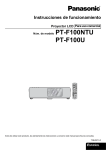
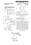
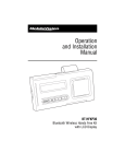
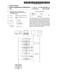
Thank you for purchasing our product.
Please read this User’s Manual before
using the product.
Change without Notice
AWT3000 Series
4" Grommet Mounted Radar
USER MANUAL
Daily Maintenance
Safety Messages to Operators of Vehicles with 3rd Eye Radar
1. The 3rd Eye Radar system is intended as an Object Detection
System and should not be relied upon as your first line of defense for
the safe operation of the vehicle. It should be used in conjunction
with established safety programs and procedures to augment the
safe operation of the vehicle, ground personnel and adjacent
property. Should the system become inoperative, it could jeopardize
the safety or livees of those who depend on the system for safety.
2. Testing and inspection of the system in accordance with these
instructions and record of the results should be listed on the daily
maintenacne report. The units on operating vehicles must be tested
each day prior to the vehicle's operation. Results of this test must
be recordeed in maintenance log.
3. People operating this equipoment must check for proper operation
at the beginning of every shift or safety inspection period.
4. People's lives depend on the proper installation of this product in
conformance with these instructions. It is necessary to read,
understand and follow all instructions shipped with the product.
5. Failure to follow all safety precautions and instructions may
result in property damage, serious injury or death.
6. The 3rd Eye Radar Object Detection system is intended for
commercial use. Proper installation of a blind-spot aid requires a
good understanding of truck electrical systems and procedures,
along with proficiency in the installation.
7. Store these instructions in a safe place and refer to them when
maintaining and/or reinstalling the product.
2
Testing and Maintenance
Note: A walk around test should be performed every day to verify proper
function of the system and to familiarize the operator with the zone of detection.
More frequent inspections should be performed when:
- The vehicle is operating in a particularly dirty or harsh environment.
- The operator has reason to suspect the system has been damaged.
- The test should be performed with two people, one who remains in the cab
(the operator), and one who walks through the sensor field to the side of the
vehicle (the assistant).
1. Clean the sensor face of any accumulation of dirt, mud, snow, ice or debris.
2. Visually inspect the attached wiring and cable and verify that they are
properly secured, not chafing or dangling free where they could become
snagged and damaged. Inspect the Radar Sensor and Operator Display
Module and verify that they are securely attached to the vehicle.
3. Set the park brakes, start the vehicle, depress and hold the vehicle brake.
4. Verify the green "POWER" light is illuminated on the in-cab display.
5. The area to the rear of the vehicle should be clear of obstacles for a
distance of 3 meters and if the display shows any indicator other than the
green light.
3
FEATURE
4
Installation Instructions
Before You Start
Prior to installing the AWT Radar System take time to familiarize yourself with
the installation instructions, theory of operation, and system components. Check
the contents of the shipping package and verify the following items are included:
1 - AWT3000-20 Radar Sensor
1 - AWT123RD Display Unit
1 - AWT32057/AWT32058 3rd Eye/Radar Adapter Set
1 - AWT32089 25 foot Interconnect Cable
User Manual/Operating Instructions and drill template
1 - AWT40700
Sensor Rubber Grommet
1 - AWT40720
Sensor Steel Mounting Hardware
1 - Bag 1/4” x 10-24 Bolts, Hex Locking Nuts, and Washers (4)
1 - Display Mounting Kit: Velcro
Radar/Sensor Location
The AWT Radar sensor mounting location is integral to proper system operation. The
sensor should be mounted in the middle of the largest blind spot area and roughly
30” (1M) +/- 12” (0.3M) above the ground. To determine the blind spot area for your
particular vehicle, have somebody sit in the driver’s seat in the normal driving
position and have another person walk the side of the truck noting where the driver
loses sight of the person walking around. The sensor face should be mounted
perpendicular to the ground with the 4” diameter radar fixture “TOP” graphic in
readable position. That is the proper orientation for the radar sensor. Select a
location that will provide an unobstructed view of the target hazard area.
5
Installation
IMPORTANT!
Before the 3rd Eye Radar System is permanently installed on the vehicle, verify that
the selected sensor mounted location provides a clear detection zone. Temporarily
attach the sensor in the proposed mounting location, apply power to the system, and
verify that nothing is being detected.
Radar Sensor Mounting
1. Select the appropriate sensor and bracket location.
2. Using the metal "L" bracket (AWT40720) use the holes as a template, scribe
postion marks through the holes. Drill 1/4" (6mm) holes centered at the marks.
3. The correct sensor fixture mounting orientation is the "TOP" up and interface
cable entering from the bottom.
4. A 1" diameter clearance hole is required for the sensor connector and the mating
cable connector.
3rd Eye Radar Sensor Adapter or Cable Installation
The interconnect cable between the radar sensor and radar display may be
integrated on either the BodyBuilder Cab Pre-Wire Harness or a 3rd Eye
MobileVision Camera System cable. For either of these the installation is basically
"plug-n-play" by using the appropriate adapters and radar extensions cables. Please
refer to the following diagram that describes in detail the necessary adapters and
cables required.
For questions call 866.804.2984
6
3rd Eye MobileVision Radar System
18-12-7 Feet Detection Zone Walk Test
Testing Instructions
Now that the 3rd Eye MobileVision Radar installation is complete, follow all of the testing instructions listed below to ensure that the system is operating correctly. Do not
use the Radar System until you have completed this testing process and have ascertained that the system is working correctly.
WARNING: USE CAUTION WHEN WORKING AROUND ANY BACKING VEHICLES
Step #1: One person should remain in the vehicle at all times. Set the parking brake.
Turn the ignition switch on and place it in reverse. At this time, a green light will appear
on the interior indicator to indicate that the unit has been activated in the proper
manner. If the green light does not come on when the vehicle is placed in reverse,
check the system to ensure that it is completely and correctly installed. It is possible if
the green light does not come on that there is not enough voltage to the system. Check
the battery with a voltage meter to ensure that there is at least 12 volts going to the
system.
Step #2: Using a tape measure, mark off a distance of eighteen feet straight out from
behind the vehicle. Ask a person to stand there. The vehicle should remain stationary
while the person begins to walk toward it from behind. When the person reaches a distance of eighteen feet from the sensor, the interior indicator should turn to a flashing
yellow/green light. When the person reaches a distance of twelve feet from the sensor,
the interior indicator should turn to a flashing red /green light and sound a fast pulsating noise. When the person is within a distance of seven feet of the sensor, the interior
indicator will show a solid red light and the noise should become continuous, warning
the driver that an object is dangerously close to the vehicle.
7
How to Walk Test the AWT3000-20 Radar System (18-12-7)
Do all tests from both sides of the sensor. (1) First, find a spot that is one foot from
the side of the sensor and 18 feet back and walk to the side of the sensor at a
normal walking pace. You should hear 3 seperate tones at 18 feet, 12 feet and 7
feet. (2) Second, find a spot that is four to five feet outside the sensor and 18 feet
back. Walk in a straight line to the outside of the bumper. You should hear two
separate tones at 18 feet and 7 feet. (3) Finally, find the same spot that was 4 feet
outside of the sensor and 18 feet to teh back (No.2). This time walk in a straight line
directly toward the unit from that spot. You should receive the same 3 signals as
the first test (NO 1) that you did at 18-7-5 feet.
8
ALL NUMBERS ARE APPROXIMATE AND MAY VARY
System Connections
In the truck cab locate the transmission's reverse switch or the back up light circuit
wire and connect the red wire from the switched power and ground harness for the
radar system. Connect the blackwire of this harness to the vehicle ground.
9
10
11
12
13