1
Generating Code for
Embedded Systems
Generating Code for Embedded Systems
© 2004 e-SIM Ltd. All rights reserved.
e-SIM Ltd.
POB 45002
Jerusalem
91450
Israel
Tel:
Fax:
972-2-5870770
972-2-5870773
Information in this manual is subject to change without notice and does not represent a commitment
on the part of the vendor. The software described in this manual is furnished under a license agreement
and may be used or copied only in accordance with the terms of that agreement. No part of this
manual may be reproduced or transmitted in any form or by any means, electronic or mechanical,
including photocopying and recording, for any purpose without the express written permission of
e-SIM Ltd.
Microsoft, Windows, Windows NT, and DOS are either registered trademarks or trademarks of
Microsoft Corporation in the United States and/or other countries.
Borland is a registered trademark of Borland Software Corporation.
Written and produced by e-SIM Ltd.
Printed in Israel.
MAN-CG-8.0
iii
Contents
About this Manual . . . . . . . . . . . . . . . . . . . . . . . . . . . . . . . . . . . . . . . . . . . . xv
Conventions Used in this Manual . . . . . . . . . . . . . . . . . . . . . . . . . . . . . . . . . xvi
C H A P T E R 1 : R A P I D P L U S A N D C C O D E G E N E R A T I O N . . . . . . . . . . . . . . . 1-1
RapidPLUS Code Generation Benefits . . . . . . . . . . . . . . . . . . . . . . . . . . . . . . . 1-2
Code Generation Terms and Concepts . . . . . . . . . . . . . . . . . . . . . . . . . . . . . . . 1-3
The ABCs of Creating an Executable RapidPLUS Application . . . . . . . . . . . . . . . 1-6
Example of Embedded RapidPLUS in Action . . . . . . . . . . . . . . . . . . . . . . . . . . . 1-8
Embedded Application Development, Step by Step . . . . . . . . . . . . . . . . . . . . . . .1-10
Step 1: Build the RapidPLUS Application . . . . . . . . . . . . . . . . . . . . . . . . . . .1-11
Step 2: Design the Embedded System . . . . . . . . . . . . . . . . . . . . . . . . . . . . .1-11
Step 3: Adapt the RapidPLUS Application . . . . . . . . . . . . . . . . . . . . . . . . . . .1-11
Step 4: Generate Code . . . . . . . . . . . . . . . . . . . . . . . . . . . . . . . . . . . . . .1-11
Step 5: Implement the Interface Layer . . . . . . . . . . . . . . . . . . . . . . . . . . . . .1-12
Step 6: Compile and Link . . . . . . . . . . . . . . . . . . . . . . . . . . . . . . . . . . . .1-12
Step 7: Load and Debug . . . . . . . . . . . . . . . . . . . . . . . . . . . . . . . . . . . . .1-12
CHAPTER 2: APPLICATION DESIGN GUIDELINES
. . . . . . . . . . . . . . . . . 2-1
Implementing User Objects . . . . . . . . . . . . . . . . . . . . . . . . . . . . . . . . . . . . . 2-2
User Object Generation Formats . . . . . . . . . . . . . . . . . . . . . . . . . . . . . . . . 2-2
General Design Considerations . . . . . . . . . . . . . . . . . . . . . . . . . . . . . . . . . 2-3
An Example Application . . . . . . . . . . . . . . . . . . . . . . . . . . . . . . . . . . . . . . . 2-9
Components . . . . . . . . . . . . . . . . . . . . . . . . . . . . . . . . . . . . . . . . . . . .2-12
Tips for Restructuring an Application . . . . . . . . . . . . . . . . . . . . . . . . . . . . . . .2-15
Creating the User Objects . . . . . . . . . . . . . . . . . . . . . . . . . . . . . . . . . . . .2-15
Integrating the User Objects . . . . . . . . . . . . . . . . . . . . . . . . . . . . . . . . . . .2-16
iv
C H A P T E R 3 : I N T E R F A C I N G W I T H G E N E R A T E D U S E R O B J E C T S . . . . . . . . 3-1
Generated Interfaces in Context . . . . . . . . . . . . . . . . . . . . . . . . . . . . . . . . . . . 3-2
What Happens in the Interface Layer . . . . . . . . . . . . . . . . . . . . . . . . . . . . . 3-3
Generated Interface Output Files . . . . . . . . . . . . . . . . . . . . . . . . . . . . . . . . . . 3-5
User Code Areas in the Output Files . . . . . . . . . . . . . . . . . . . . . . . . . . . . . . 3-5
Generated Interface Files . . . . . . . . . . . . . . . . . . . . . . . . . . . . . . . . . . . . . 3-6
Generated Macros . . . . . . . . . . . . . . . . . . . . . . . . . . . . . . . . . . . . . . . . 3-10
Triggering Events . . . . . . . . . . . . . . . . . . . . . . . . . . . . . . . . . . . . . . . . . . . 3-12
Getting or Setting Property Values. . . . . . . . . . . . . . . . . . . . . . . . . . . . . . . . . 3-12
Implementing Exported Functions . . . . . . . . . . . . . . . . . . . . . . . . . . . . . . . . 3-13
Exported Function Parameters . . . . . . . . . . . . . . . . . . . . . . . . . . . . . . . . . 3-13
Implementing Exported Unions . . . . . . . . . . . . . . . . . . . . . . . . . . . . . . . . . . 3-14
Sending a Structure from the Embedded System to RapidPLUS . . . . . . . . . . . . . 3-15
Handling a Structure in the RapidPLUS Application . . . . . . . . . . . . . . . . . . . . 3-18
C H A P T E R 4 : T H E A P P L I C A T I O N P R O G R A M M I N G I N T E R F A C E ( A P I ) . . . . 4-1
RapidPLUS vs. Callback Functions . . . . . . . . . . . . . . . . . . . . . . . . . . . . . . . . . 4-2
Runtime API . . . . . . . . . . . . . . . . . . . . . . . . . . . . . . . . . . . . . . . . . . . . . . 4-2
Runtime API at a Glance . . . . . . . . . . . . . . . . . . . . . . . . . . . . . . . . . . . . . 4-2
Runtime API in Context . . . . . . . . . . . . . . . . . . . . . . . . . . . . . . . . . . . . . 4-3
The State Machine and the “More To Do” Return Value . . . . . . . . . . . . . . . . . . 4-4
Using the Runtime API . . . . . . . . . . . . . . . . . . . . . . . . . . . . . . . . . . . . . . 4-5
Timer Request API . . . . . . . . . . . . . . . . . . . . . . . . . . . . . . . . . . . . . . . . . . . 4-8
Registering the Callback Functions . . . . . . . . . . . . . . . . . . . . . . . . . . . . . . . 4-9
Activating the Timer . . . . . . . . . . . . . . . . . . . . . . . . . . . . . . . . . . . . . . 4-10
Stopping the Timer . . . . . . . . . . . . . . . . . . . . . . . . . . . . . . . . . . . . . . . 4-11
Timer Expiration Function . . . . . . . . . . . . . . . . . . . . . . . . . . . . . . . . . . 4-11
Summary . . . . . . . . . . . . . . . . . . . . . . . . . . . . . . . . . . . . . . . . . . . . . 4-12
Dynamic Allocation API for User Object Holders . . . . . . . . . . . . . . . . . . . . . . . . 4-15
Dynamic Allocation API at a Glance . . . . . . . . . . . . . . . . . . . . . . . . . . . . . 4-15
Using the Dynamic Allocation API . . . . . . . . . . . . . . . . . . . . . . . . . . . . . . 4-15
Image API . . . . . . . . . . . . . . . . . . . . . . . . . . . . . . . . . . . . . . . . . . . . . . . 4-18
Using the Image API . . . . . . . . . . . . . . . . . . . . . . . . . . . . . . . . . . . . . . . 4-18
v
Debug API . . . . . . . . . . . . . . . . . . . . . . . . . . . . . . . . . . . . . . . . . . . . . . . .4-20
The Debug API at a Glance . . . . . . . . . . . . . . . . . . . . . . . . . . . . . . . . . . .4-21
Debug API in Context . . . . . . . . . . . . . . . . . . . . . . . . . . . . . . . . . . . . . .4-22
Using the Debug API . . . . . . . . . . . . . . . . . . . . . . . . . . . . . . . . . . . . . . .4-23
Generated Text Files That Aid in Debugging . . . . . . . . . . . . . . . . . . . . . . . . .4-31
C ANSI Standard Runtime Functions . . . . . . . . . . . . . . . . . . . . . . . . . . . . . . . .4-34
C H A P T E R 5 : I N T E G R A T I N G A N A P P L I C A T I O N . . . . . . . . . . . . . . . . . . . . 5-1
The RapidPLUS Task in Context . . . . . . . . . . . . . . . . . . . . . . . . . . . . . . . . . . . 5-2
Generating the Example Application . . . . . . . . . . . . . . . . . . . . . . . . . . . . . . . . 5-3
The Output Files . . . . . . . . . . . . . . . . . . . . . . . . . . . . . . . . . . . . . . . . . . 5-4
Writing the Interface Layer. . . . . . . . . . . . . . . . . . . . . . . . . . . . . . . . . . . . . . 5-4
Implementing the Generated Interfaces . . . . . . . . . . . . . . . . . . . . . . . . . . . . 5-5
Writing the Translation Code . . . . . . . . . . . . . . . . . . . . . . . . . . . . . . . . . . 5-8
Handling Logic-Generated Events . . . . . . . . . . . . . . . . . . . . . . . . . . . . . . .5-14
Floating Point Support . . . . . . . . . . . . . . . . . . . . . . . . . . . . . . . . . . . . . . . .5-15
Message Structures that Contain Number Fields . . . . . . . . . . . . . . . . . . . . . . .5-15
Compiling and Linking the Application . . . . . . . . . . . . . . . . . . . . . . . . . . . . . .5-16
C H A P T E R 6 : I N T E G R A T I N G G R A P H I C D I S P L A Y S . . . . . . . . . . . . . . . . . . 6-1
Glossary . . . . . . . . . . . . . . . . . . . . . . . . . . . . . . . . . . . . . . . . . . . . . . . . . 6-2
Preparing Graphic Elements for Code Generation . . . . . . . . . . . . . . . . . . . . . . . . 6-6
For the Font, Bitmap, and Image Objects . . . . . . . . . . . . . . . . . . . . . . . . . . . 6-6
For the Palette-Based Graphic Display Object . . . . . . . . . . . . . . . . . . . . . . . . 6-6
For the True Color Graphic Display Object . . . . . . . . . . . . . . . . . . . . . . . . . . 6-8
Selecting a Bitmap Format DLL . . . . . . . . . . . . . . . . . . . . . . . . . . . . . . . . .6-10
Graphic Display—Embedded System Integration . . . . . . . . . . . . . . . . . . . . . . . .6-12
How Graphic Display – Graphic Device Compatibility is Achieved . . . . . . . . . . .6-12
For a Graphic Display That Uses fd_co.dll, fd_ro.dll, or fd_tc24.dll . . . . . . . . . . .6-13
For a True Color Graphic Display That Uses tc_fmt.dll . . . . . . . . . . . . . . . . . . .6-16
Integrating a Graphic Display . . . . . . . . . . . . . . . . . . . . . . . . . . . . . . . . . .6-19
Integrating a Palette-Based Graphic Display Object . . . . . . . . . . . . . . . . . . . . .6-19
Integrating a True Color Graphic Display Object . . . . . . . . . . . . . . . . . . . . . .6-22
Graphic Display Integration, an Example . . . . . . . . . . . . . . . . . . . . . . . . . . .6-24
The Embedded Graphic Display in Action . . . . . . . . . . . . . . . . . . . . . . . . . .6-26
vi
Embedded Bitmap and Image Objects . . . . . . . . . . . . . . . . . . . . . . . . . . . . . . 6-28
For Image Objects Only . . . . . . . . . . . . . . . . . . . . . . . . . . . . . . . . . . . . . 6-28
Generated Bitmap Data . . . . . . . . . . . . . . . . . . . . . . . . . . . . . . . . . . . . . 6-29
Customized Bitmap Format DLL . . . . . . . . . . . . . . . . . . . . . . . . . . . . . . . 6-30
Example of Packing a Bitmap . . . . . . . . . . . . . . . . . . . . . . . . . . . . . . . . . 6-41
Embedded Font Object . . . . . . . . . . . . . . . . . . . . . . . . . . . . . . . . . . . . . . . 6-42
Embedded Graphic Display Object . . . . . . . . . . . . . . . . . . . . . . . . . . . . . . . . 6-42
Color Support . . . . . . . . . . . . . . . . . . . . . . . . . . . . . . . . . . . . . . . . . . . 6-42
Device Context . . . . . . . . . . . . . . . . . . . . . . . . . . . . . . . . . . . . . . . . . . . . 6-43
Low-Level Driver . . . . . . . . . . . . . . . . . . . . . . . . . . . . . . . . . . . . . . . . . . . 6-45
Hardware ID . . . . . . . . . . . . . . . . . . . . . . . . . . . . . . . . . . . . . . . . . . . 6-45
Driver API . . . . . . . . . . . . . . . . . . . . . . . . . . . . . . . . . . . . . . . . . . . . . 6-45
Graphic Display Library . . . . . . . . . . . . . . . . . . . . . . . . . . . . . . . . . . . . . . . 6-49
Format Drivers . . . . . . . . . . . . . . . . . . . . . . . . . . . . . . . . . . . . . . . . . . 6-50
Debugging the GDL . . . . . . . . . . . . . . . . . . . . . . . . . . . . . . . . . . . . . . . 6-50
Debugging Graphic Displays . . . . . . . . . . . . . . . . . . . . . . . . . . . . . . . . . . . . 6-50
C H A P T E R 7 : S P L I T T I N G T H E R A P I D P L U S A N D G R A P H I C T A S K S . . . . . . . 7-1
Split Tasks Architecture . . . . . . . . . . . . . . . . . . . . . . . . . . . . . . . . . . . . . . . . 7-2
The ABCs of Creating an Executable RapidPLUS Application
Comprised of Two Tasks . . . . . . . . . . . . . . . . . . . . . . . . . . . . . . . . . . . . . 7-2
Building an Application that Will be Split . . . . . . . . . . . . . . . . . . . . . . . . . . . . . 7-4
Requirements for Building a Graphic Task . . . . . . . . . . . . . . . . . . . . . . . . . . 7-4
Building the Graphic Task . . . . . . . . . . . . . . . . . . . . . . . . . . . . . . . . . . . . 7-5
The Generated Source Files . . . . . . . . . . . . . . . . . . . . . . . . . . . . . . . . . . . . 7-5
Writing the Interface Layer . . . . . . . . . . . . . . . . . . . . . . . . . . . . . . . . . . . . . . 7-6
Step 1. Initializing the Graphic Task . . . . . . . . . . . . . . . . . . . . . . . . . . . . . . 7-6
Step 2: Connecting the Graphic Task to the Task Interface . . . . . . . . . . . . . . . . . 7-8
Step 3: Initializing the RapidPLUS Task . . . . . . . . . . . . . . . . . . . . . . . . . . . . 7-9
Step 4: Adding Additional Functions and Logic . . . . . . . . . . . . . . . . . . . . . . . 7-9
Example of Split Tasks . . . . . . . . . . . . . . . . . . . . . . . . . . . . . . . . . . . . . . . . . 7-9
Architecture of the Split Tasks Communications . . . . . . . . . . . . . . . . . . . . . . 7-11
Building Communications Overview . . . . . . . . . . . . . . . . . . . . . . . . . . . . . 7-12
Building the Control Set for the Embedded Graphic Task . . . . . . . . . . . . . . . . 7-12
vii
Building the Control Set for the Embedded RapidPLUS Task . . . . . . . . . . . . . . .7-15
Building the Main Control Set . . . . . . . . . . . . . . . . . . . . . . . . . . . . . . . . .7-17
Building the Control Set for the Messages . . . . . . . . . . . . . . . . . . . . . . . . . .7-18
Implementing the sendMsg Function . . . . . . . . . . . . . . . . . . . . . . . . . . . . .7-19
Implementing the getMsg Function . . . . . . . . . . . . . . . . . . . . . . . . . . . . . .7-19
Adding Supplemental Functions and Logic . . . . . . . . . . . . . . . . . . . . . . . . . .7-20
C H A P T E R 8 : M U L T I P L E A P P L I C A T I O N S U P P O R T . . . . . . . . . . . . . . . . . . 8-1
Overview of Multiple Application Support . . . . . . . . . . . . . . . . . . . . . . . . . . . . 8-2
Building Applications that will be Linked Together . . . . . . . . . . . . . . . . . . . . . . . 8-3
Building Two or More Stand-Alone Applications . . . . . . . . . . . . . . . . . . . . . . 8-3
Generating Several Instances of the Same Application . . . . . . . . . . . . . . . . . . . 8-4
Building a Single Application that is Separated into Several Tasks . . . . . . . . . . . . 8-4
Using the Multitask API . . . . . . . . . . . . . . . . . . . . . . . . . . . . . . . . . . . . . . . . 8-6
Runtime API . . . . . . . . . . . . . . . . . . . . . . . . . . . . . . . . . . . . . . . . . . . . 8-7
Timer Request API . . . . . . . . . . . . . . . . . . . . . . . . . . . . . . . . . . . . . . . . .8-10
Dynamic Allocation API for User Object Holders . . . . . . . . . . . . . . . . . . . . . .8-11
Image API . . . . . . . . . . . . . . . . . . . . . . . . . . . . . . . . . . . . . . . . . . . . . .8-13
Debug API . . . . . . . . . . . . . . . . . . . . . . . . . . . . . . . . . . . . . . . . . . . . .8-14
User Data API . . . . . . . . . . . . . . . . . . . . . . . . . . . . . . . . . . . . . . . . . . .8-17
Functions for Integrating a Graphic Display . . . . . . . . . . . . . . . . . . . . . . . . . . .8-18
Low-Level Driver API . . . . . . . . . . . . . . . . . . . . . . . . . . . . . . . . . . . . . . .8-18
Graphic Display Library API . . . . . . . . . . . . . . . . . . . . . . . . . . . . . . . . . . .8-19
Code Example for Integrating a Graphic Display . . . . . . . . . . . . . . . . . . . . . .8-20
Splitting the Graphic Task From the Main Task . . . . . . . . . . . . . . . . . . . . . . . . .8-21
The Similarities and Differences Between
a Stand-Alone Application and a Graphic Task . . . . . . . . . . . . . . . . . . . . . . .8-21
Generating a Graphic Task in the Multitask Environment. . . . . . . . . . . . . . . . .8-22
Changes to Generated Interface . . . . . . . . . . . . . . . . . . . . . . . . . . . . . . . . . . .8-23
viii
C H A P T E R 9 : O P T I M I Z I N G A P P L I C A T I O N P E R F O R M A N C E . . . . . . . . . . . . 9-1
Mode Activities and Condition-Only Transitions . . . . . . . . . . . . . . . . . . . . . . . . . 9-2
Mode Activities . . . . . . . . . . . . . . . . . . . . . . . . . . . . . . . . . . . . . . . . . . . 9-2
Condition-Only Triggers . . . . . . . . . . . . . . . . . . . . . . . . . . . . . . . . . . . . . 9-2
Transition Time . . . . . . . . . . . . . . . . . . . . . . . . . . . . . . . . . . . . . . . . . . . . . 9-2
Setting Data Size . . . . . . . . . . . . . . . . . . . . . . . . . . . . . . . . . . . . . . . . . . . . 9-3
Using Constant Objects . . . . . . . . . . . . . . . . . . . . . . . . . . . . . . . . . . . . . . . . 9-4
Using Constant Objects in If...Else Branches . . . . . . . . . . . . . . . . . . . . . . . . . 9-4
Using Primitive Data Objects . . . . . . . . . . . . . . . . . . . . . . . . . . . . . . . . . . . . . 9-5
Behavior of Number Objects . . . . . . . . . . . . . . . . . . . . . . . . . . . . . . . . . . . . . 9-5
C H A P T E R 1 0 : U S I N G T H E C O D E G E N E R A T O R . . . . . . . . . . . . . . . . . . . . 10-1
Specifying the Code Generation Preferences . . . . . . . . . . . . . . . . . . . . . . . . . . . 10-2
General Preferences . . . . . . . . . . . . . . . . . . . . . . . . . . . . . . . . . . . . . . . 10-3
Debug Preferences . . . . . . . . . . . . . . . . . . . . . . . . . . . . . . . . . . . . . . . . 10-4
Text Preferences . . . . . . . . . . . . . . . . . . . . . . . . . . . . . . . . . . . . . . . . . 10-7
Optimization Preferences . . . . . . . . . . . . . . . . . . . . . . . . . . . . . . . . . . . 10-8
Data Size Preferences . . . . . . . . . . . . . . . . . . . . . . . . . . . . . . . . . . . . . 10-10
Buffer and Queue Preferences . . . . . . . . . . . . . . . . . . . . . . . . . . . . . . . . 10-10
Miscellaneous Preferences . . . . . . . . . . . . . . . . . . . . . . . . . . . . . . . . . . 10-14
Generating Components . . . . . . . . . . . . . . . . . . . . . . . . . . . . . . . . . . . 10-18
Generating the Code . . . . . . . . . . . . . . . . . . . . . . . . . . . . . . . . . . . . . . . . 10-21
Starting Code Generation . . . . . . . . . . . . . . . . . . . . . . . . . . . . . . . . . . 10-21
Stopping the Code Generation Process. . . . . . . . . . . . . . . . . . . . . . . . . . . 10-25
Nongenerated Elements . . . . . . . . . . . . . . . . . . . . . . . . . . . . . . . . . . . . . . 10-25
A P P E N D I X A : G L O S S A R Y . . . . . . . . . . . . . . . . . . . . . . . . . . . . . . . . . . . . A-1
A P P E N D I X B : I N S T A L L E D C O D E G E N E R A T I O N F I L E S . . . . . . . . . . . . . . . B-1
A P P E N D I X C : G E N E R A T E D A N D N O N G E N E R A T E D O B J E C T S . . . . . . . . . . C-1
List of Generated Objects . . . . . . . . . . . . . . . . . . . . . . . . . . . . . . . . . . . . . C-2
ix
A P P E N D I X D : M E M O R Y U S A G E . . . . . . . . . . . . . . . . . . . . . . . . . . . . . . . D-1
ROM Usage . . . . . . . . . . . . . . . . . . . . . . . . . . . . . . . . . . . . . . . . . . . . . . . D-1
RAM Usage . . . . . . . . . . . . . . . . . . . . . . . . . . . . . . . . . . . . . . . . . . . . . . . D-2
A P P E N D I X E : E R R O R S , W A R N I N G S , A N D M E S S A G E S . . . . . . . . . . . . . . . E-1
Generation Errors, Warnings, and Messages . . . . . . . . . . . . . . . . . . . . . . . . . . . E-1
Errors (E) . . . . . . . . . . . . . . . . . . . . . . . . . . . . . . . . . . . . . . . . . . . . . . E-2
Warnings (W) . . . . . . . . . . . . . . . . . . . . . . . . . . . . . . . . . . . . . . . . . . . E-5
Informational Messages (I) . . . . . . . . . . . . . . . . . . . . . . . . . . . . . . . . . . . E-7
Runtime Errors . . . . . . . . . . . . . . . . . . . . . . . . . . . . . . . . . . . . . . . . . . . . . E-8
APPENDIX F: RAPIDPLUS OBJECT MANIPULATION FUNCTIONS
. . . . . . F-1
Object Manipulation Functions at a Glance. . . . . . . . . . . . . . . . . . . . . . . . . . . . F-2
Arrays: Integer . . . . . . . . . . . . . . . . . . . . . . . . . . . . . . . . . . . . . . . . . . . . . F-6
Arrays: Number . . . . . . . . . . . . . . . . . . . . . . . . . . . . . . . . . . . . . . . . . . . . . F-7
Arrays: String . . . . . . . . . . . . . . . . . . . . . . . . . . . . . . . . . . . . . . . . . . . . . . F-8
Integer, Number, and String Objects . . . . . . . . . . . . . . . . . . . . . . . . . . . . . . . .F-10
Date Object . . . . . . . . . . . . . . . . . . . . . . . . . . . . . . . . . . . . . . . . . . . . . . .F-11
Time Object . . . . . . . . . . . . . . . . . . . . . . . . . . . . . . . . . . . . . . . . . . . . . . .F-12
Timer Object . . . . . . . . . . . . . . . . . . . . . . . . . . . . . . . . . . . . . . . . . . . . . .F-13
Stopwatch Object . . . . . . . . . . . . . . . . . . . . . . . . . . . . . . . . . . . . . . . . . . .F-16
Event Object . . . . . . . . . . . . . . . . . . . . . . . . . . . . . . . . . . . . . . . . . . . . . .F-18
Bitmap Object . . . . . . . . . . . . . . . . . . . . . . . . . . . . . . . . . . . . . . . . . . . . .F-19
Image Object . . . . . . . . . . . . . . . . . . . . . . . . . . . . . . . . . . . . . . . . . . . . . .F-20
Font Object . . . . . . . . . . . . . . . . . . . . . . . . . . . . . . . . . . . . . . . . . . . . . . .F-22
Graphic Displays (GDO) . . . . . . . . . . . . . . . . . . . . . . . . . . . . . . . . . . . . . . .F-25
Graphic Display Buffer Functions . . . . . . . . . . . . . . . . . . . . . . . . . . . . . . . . . .F-55
Unique Buffer Functions . . . . . . . . . . . . . . . . . . . . . . . . . . . . . . . . . . . .F-56
x
A P P E N D I X G : G D L A N D F O R M A T D R I V E R A P I . . . . . . . . . . . . . . . . . . . .G-1
Error Codes . . . . . . . . . . . . . . . . . . . . . . . . . . . . . . . . . . . . . . . . . . . . . . .G-2
GDL Compilation Defines . . . . . . . . . . . . . . . . . . . . . . . . . . . . . . . . . . . . . .G-2
GDL and Format Driver API at a Glance . . . . . . . . . . . . . . . . . . . . . . . . . . . . . .G-3
GDL API . . . . . . . . . . . . . . . . . . . . . . . . . . . . . . . . . . . . . . . . . . . . . . .G-3
Format Driver API . . . . . . . . . . . . . . . . . . . . . . . . . . . . . . . . . . . . . . . . .G-6
GDL Integration API . . . . . . . . . . . . . . . . . . . . . . . . . . . . . . . . . . . . . . .G-8
Using the GDL API . . . . . . . . . . . . . . . . . . . . . . . . . . . . . . . . . . . . . . . . . . .G-8
Using the Format Driver API . . . . . . . . . . . . . . . . . . . . . . . . . . . . . . . . . . . . G-26
Using the Integration API . . . . . . . . . . . . . . . . . . . . . . . . . . . . . . . . . . . . . . G-41
A P P E N D I X H : D R I V E R E X A M P L E S . . . . . . . . . . . . . . . . . . . . . . . . . . . . . . H-1
A P P E N D I X I : C O M P I L A T I O N D E F I N E S . . . . . . . . . . . . . . . . . . . . . . . . . . I-1
A P P E N D I X J : D E S C R I P T I O N O F E X A M P L E A P P L I C A T I O N . . . . . . . . . . . . J-1
The System Requirements . . . . . . . . . . . . . . . . . . . . . . . . . . . . . . . . . . . . . . . J-1
The RapidPLUS Application . . . . . . . . . . . . . . . . . . . . . . . . . . . . . . . . . . . . . . J-5
Objects . . . . . . . . . . . . . . . . . . . . . . . . . . . . . . . . . . . . . . . . . . . . . . . . J-5
Modes . . . . . . . . . . . . . . . . . . . . . . . . . . . . . . . . . . . . . . . . . . . . . . . . J-6
I N D E X . . . . . . . . . . . . . . . . . . . . . . . . . . . . . . . . . . . . . . . . . . . . . . . . . . 1-1
xi
ABOUT THIS MANUAL
The Generating Code for Embedded Systems manual provides the information
you need to use RapidPLUS’s C code generation features. It refers to
information presented in the Rapid User Manual, User Manual Supplement,
and Methodology Guide: Building Applications for Embedded Systems.
This manual comprises the following chapters:
•
Chapter 1: “RapidPLUS and C Code Generation“ is an overview of the
RapidPLUS code generation process.
•
Chapter 2: “Application Design Guidelines“discusses how to design the
architecture of a RapidPLUS application that is going to be generated as an
embedded application.
•
Chapter 3: “Interfacing with Generated User Objects“explains in detail
how to build the part of the RapidPLUS–embedded system interface layer
that implements generated user objects in the embedded system context.
•
Chapter 4: “The Application Programming Interface (API)“describes the
API libraries that RapidPLUS makes available to the embedded system
integrator. These libraries are used when the single-task API is selected.
•
Chapter 5: “Integrating an Application“presents a detailed example of
integrating a generated application into an embedded system
environment.
•
Chapter 6: “Integrating Graphic Displays“ deals with the embedded
graphic display—its architecture, its principles of operation in the
embedded system context, and how to integrate the RapidPLUS-generated
object with the system’s physical display device.
•
Chapter 7: “Splitting the RapidPLUS and Graphic Tasks“ explains how to
build an application and interface layer so that the graphic operations can
be split from the main task and placed in a separate task.
•
Chapter 8: “Multiple Application Support“ describes the methodology for
developing RapidPLUS applications that will be linked together and the
multitask API.
•
Chapter 9: “Optimizing Application Performance“ discusses how to build
the RapidPLUS application logic so as to optimize the performance (that is,
memory usage and speed of execution) of the embedded application.
•
Chapter 10: “Using the Code Generator“ explains code generation
preference settings and what happens during the code generation process.
xii
•
Appendix A: “Glossary“ presents a glossary of terms relevant to RapidPLUS
and C code generation.
•
Appendix B: “Installed Code Generation Files“ presents the folders that are
installed when RapidPLUS is installed that relate to C code generation.
•
Appendix C: “Generated and Nongenerated Objects“ lists the RapidPLUS
objects that can be generated.
•
Appendix D: “Memory Usage“ describes which generated RapidPLUS data
is stored in ROM and which is stored in RAM.
•
Appendix E: “Errors, Warnings, and Messages“ presents information that
appears when generating code and runtime error messages.
•
Appendix F: “RapidPLUS Object Manipulation Functions“ describes
functions that can be used for manipulating RapidPLUS objects that are
passed as parameters by exported functions.
•
Appendix G: “GDL and Format Driver API“ describes functions that are
available through the graphic display library.
•
Appendix H: “Driver Examples“ presents two low-level driver files.
•
Appendix I: “Compilation Defines“ describes the RapidPLUS compilation
define flags.
•
Appendix J: “Description of Example Application“presents an example
application that illustrates code generation issues.
CONVENTIONS USED IN THIS MANUAL
RapidPLUS’s documentation uses the following conventions:
•
“Choose File|Save Application” means to select the Save Application
command from the File menu.
•
Names of properties, functions, and events appear in italic characters:
rpd_PrivInitTask
•
Complete phrases of RapidPLUS logic appear in bold, sans serif characters:
TimerObject resetCount
•
C code appears in monospaced characters:
RINT rpd_PrivInitTask(User_ErrorFunc errorFunc);
1-1
C
H
A
P
T
E
R
1
RapidPLUS and
C Code Generation
The RapidPLUS prototype development tools produce a fully-functioning
virtual prototype of an embedded system—with an emphasis on modeling
the system’s man-machine interface (MMI). This virtual prototype runs in
the Microsoft® Windows environment only.
With C code generation, it is possible to transform the virtual prototype into
an executable RapidPLUS application that runs on a real embedded system.
In a typical multitasking embedded system, the generated RapidPLUS
application, or the RapidPLUS task, would run the system’s man-machine
interface task.
This chapter presents:
•
How C code generation benefits the product development cycle.
•
Terms and concepts that are basic to code generation in RapidPLUS.
•
An overview of the C code generation environment, with an example.
•
The basic steps of a typical code generation process.
R A P I D P L U S
A N D
C
C O D E
G E N E R A T I O N
1-2
RAPIDPLUS CODE GENERATION BENEFITS
Shorter
development
cycle
In the RapidPLUS paradigm, the initial virtual prototype is independent
of the embedded system’s specific hardware and software requirements.
Thus, a RapidPLUS specialist can develop the RapidPLUS prototype at the
same time that the embedded system integrator designs the system
architecture.
When these concurrent tasks are completed, it is a relatively simple matter
for the RapidPLUS specialist to adapt the RapidPLUS application so that it can
be integrated seamlessly into the embedded system environment.
❖ NOTE: Once C code is generated, the embedded system integrator adds a
thin interface layer by writing code that facilitates two-way communication
between the generated RapidPLUS application and the underlying embedded
system.
Optimized
code
The code that RapidPLUS adds to the embedded system software is
particularly sensitive to the storage, memory usage, and performance needs
of embedded systems. In addition, because the generated code is easily ported
to many platforms, the system designer can delay decisions concerning the
embedded system’s processor and real-time operating system.
Ease of
debugging
RapidPLUS provides a code generation API (application programming
interface) whose functions can be called from the interface layer. Using
the debug API, the generated RapidPLUS application can be monitored in
terms of RapidPLUS modes, transitions, and objects as it runs on the target
platform.
Possible configurations, for example, would be to send the RapidPLUS debug
information to the embedded system’s debugger or to an ASCII terminal.
These debug facilities are conducive to iterative development, promoting
earlier and less costly error reduction.
C O D E
G E N E R A T I O N
T E R M S
A N D
C O N C E P T S
1-3
CODE GENERATION TERMS AND CONCEPTS
This section defines terms and concepts that are basic to C code generation
in RapidPLUS. The section, “The ABCs of Creating an Executable RapidPLUS
Application” on p. 1-6, shows how these elements come together to create
the embedded RapidPLUS application.
❖ IMPORTANT: The C code produced by RapidPLUS complies with the ANSI C
standard. ANSI C refers to the American National Standard for Information
Systems Programming Language C, ANSI X3.159-1989. The ISO starndard
representing ANSI C is ISO standard (ISO/IEC 9899:1990).
Embedded System
An embedded system is hardware and software that is part of a larger
system and functions without human intervention. A typical embedded
system consists of a single-board microcomputer with software in ROM,
which starts running a special-purpose application program as soon as it
is turned on and does not stop until it is turned off.
An embedded system typically has to provide real-time response and may
or may not include some kind of operating system. A multitasking embedded
system can run several applications (tasks) simultaneously. Each application
has its own memory space, and means are provided for communication
among the tasks.
Code Generator
The Code Generator is a RapidPLUS module that produces a header (*.h)
and a program (*.c) file for the currently loaded RapidPLUS application and
each of its user objects. These C source code files translate the RapidPLUS
objects, modes, transitions, triggers, and activities from their native
RapidPLUS syntax into C data structures and functions.
Microkernel
The C source code files alone are not sufficient for running the RapidPLUS
application in the embedded system. The compiled C source code files
must be linked to the RapidPLUS microkernel—the virtual machine that runs
the generated application on the target platform.
The embedded microkernel is a library that implements the embedded state
machine and the RapidPLUS object methods, for those objects supported by
R A P I D P L U S
A N D
C
C O D E
G E N E R A T I O N
1-4
code generation. The microkernel ensures that the generated RapidPLUS
application behaves identically to the original RapidPLUS application.
❖ NOTE: RapidPLUS provides the microkernel library for the embedded system’s
processor and compiler.
User Objects and Code Generation
User objects are RapidPLUS applications that have been built with an
interface so they can be used as encapsulated objects inside another
RapidPLUS application (called the parent application). The parent application
sees the user object like any other RapidPLUS object.
A user object’s interface to the parent application is comprised of exported
properties, exported events, exported functions, and messages (structure
unions). Exported properties, events, and functions are described in the
Rapid User Manual. Messages are described in the User Manual Supplement.
In the code generation context, the parent application represents the
embedded system’s RapidPLUS task while its user objects represent “real-life”
components or modules, such as keypads, switches, displays, or protocol
stacks. The interface between the parent application and its user objects
represents the interface between the RapidPLUS task and the rest of the
embedded system. Inputs and outputs are defined in terms of the parent
application.
When it comes time to generate the application, you can choose to generate
a user object in one of several ways. Let’s look at two ways. You could generate
the user object in its entirety (including its objects and internal logic) or as
a generated interface. In the latter case, the Code Generator ignores the
objects and internal logic of the user object and generates only the user
object’s interface to the parent application.
Example
In the RapidPLUS prototype of an embedded system that includes a keypad
and an LCD display, you would build:
•
A keypad user object (with RapidPLUS pushbuttons) that triggers an
appropriate exported event in the parent application each time a key is
pressed.
•
An LCD user object (with a RapidPLUS text display) with an exported user
function that displays a string passed as an argument when the function
is called by the parent application.
In the real-life embedded system, however, the RapidPLUS objects that
were essential in the simulation environment (such as the pushbuttons
C O D E
G E N E R A T I O N
T E R M S
A N D
C O N C E P T S
1-5
and the display) are no longer relevant. They are replaced by actual hardware
components. Thus, you would generate both user objects as interfaces only.
In the design of the embedded system software, you would ensure that each
time a hardware key is pressed, a system message is sent to the RapidPLUS
task. The system message triggers the appropriate exported event of the
keypad generated interface.
The exported event then triggers the same logic in the embedded RapidPLUS
application as it did in the simulation environment—that is, it calls the user
function of the LCD generated interface in order to show the appropriate digit
on the real-life display.
Interface Layer
Read the last sentence of the previous paragraph one more time.
How is it possible that a user function written for a RapidPLUS display object
could cause a digit to be displayed on an unknown hardware module?
The answer lies in the interface layer that is implemented by the embedded
system integrator and comprises all user code that links the RapidPLUS task
to the embedded system software. The interface layer must ensure that:
•
Output from the RapidPLUS task is meaningful to the underlying
embedded system.
•
Input to the RapidPLUS task is translated into structures understood by
RapidPLUS.
Much of the output from the RapidPLUS task originates from exported
functions of user objects generated as interfaces only. RapidPLUS generates
exported functions as empty functions. In the user object’s generated source
code file, the embedded system integrator writes C code that implements
these functions in terms that are meaningful to the embedded system.
In the example given in the previous section of a user function that displays
a string passed as an argument, the embedded system integrator must write
the C code required by the system’s specific LCD driver in order to display
the appropriate digit.
RapidPLUS-supplied object manipulation functions facilitate writing the C
code for RapidPLUS objects passed as arguments to exported functions. These
functions are described in Appendix F: “RapidPLUS Object Manipulation
Functions.”
The interface layer also manages system inputs into the RapidPLUS task.
This part of the interface layer may be written in any file or files, as long as
these file(s) are compiled together with the generated source code files.
R A P I D P L U S
A N D
C
C O D E
G E N E R A T I O N
1-6
RapidPLUS provides an application programming interface (API) whose
functions can be called from the interface layer. Through these functions,
you:
•
Initialize, start, and end the RapidPLUS task.
•
Update the RapidPLUS timer objects.
•
Implement system responses to RapidPLUS runtime errors.
•
Debug the RapidPLUS application as it runs on the embedded system
platform—in native RapidPLUS terms of objects, modes, transitions,
and activities.
These functions are described in Chapter 4: “The Application Programming
Interface (API).”
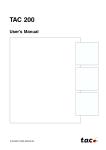
The ABCs of Creating an Executable RapidPLUS Application
The illustration on the following page shows how the elements described in
the previous section come together to create an executable RapidPLUS
application (the RapidPLUS task).
The code generation process can be summarized as follows:
A The Code Generator translates the RapidPLUS application and each of its
user objects into C source code files. In this example, the user object
is generated as an interface only.
B The embedded system integrator writes a thin interface layer, ensuring
that the functions of user objects generated as interfaces only are
implemented in terms meaningful to the embedded system, and system
messages are translated into the data structure understood by RapidPLUS.
Calls to RapidPLUS-supplied functions and macros initiate and start the
RapidPLUS task, pass system messages, and update its timer objects.
C Using the embedded system’s compiler and linker, the generated source
code files and the interface code are compiled and then linked with the
precompiled microkernel. The result is an executable RapidPLUS
application (the RapidPLUS task) which is, in turn, linked with the rest of
the embedded system software to create an executable image for
downloading to the target platform.
C O D E
G E N E R A T I O N
T E R M S
A N D
C O N C E P T S
1-7
IN SIMULATION ENVIRONMENT
GENERATED SOURCE CODE
FILES
RapidPLUS Application
myApp.h
myApp.c
User Object
Interface:
* Events
* Properties
* Structures
* Unions of
structures
* Functions
A
Internal
objects and
logic
myObject.h
myObject.c
Code Generator
GENERATED SOURCE CODE
FILES
myApp.h
myApp.c
User-written Interface
Layer
B
Calls to
RapidPLUS
API functions
myObject.h
myObject.c
Implement
exported
functions
Compile
System-toRapidPLUS
message
translator
Executable RapidPLUS Application or RapidPLUS Task
GENERATED SOURCE CODE
FILES myApp.h
myApp.c
User-written Interface
Layer
Calls to
C
RapidPLUS
API functions
myObject.h
myObject.c
Implement
exported
functions
System-toRapidPLUS
message
translator
Link
Precompiled
RapidPLUS
Microkernel
R A P I D P L U S
A N D
C
C O D E
G E N E R A T I O N
1-8
EXAMPLE OF EMBEDDED RAPIDPLUS IN
ACTION
The illustration on the following page uses a key press on a cell phone
to illustrate one possible way that a generated RapidPLUS application might
function within an embedded system.
STEP
and DESCRIPTION
The user presses a hardware key on the cell
phone and the result is captured by the
keyboard driver.
Based on the interface code written by the
embedded system integrator, the interface
layer forwards the hardware request by calling
a RapidPLUS-supplied macro.
The state machine in the microkernel reads
the message and invokes the appropriate
RapidPLUS application logic.
For example, the RapidPLUS event key_Call in may
trigger an internal transition which, in turn,
calls the exported function displayKey:
<pushbutton index> in a user object named
Display.udo. The output of the function call is
to display an appropriate string at a specific
location in the LCD display.
Based on the interface code written by the
embedded system integrator, embedded RapidPLUS
calls the display driver entry point that knows
exactly how the string is to be displayed on
the specific hardware LCD display.
The display driver displays the string.
E X A M P L E
O F
E M B E D D E D
R A P I D P L U S
I N
A C T I O N
1-9
Interface layer:
Translates and
sends the system
message
Kernel event
(KeyPressed
message)
Captured
event
Keyboard driver
Key
pressed
Display
data
Embedded RapidPLUS
Embedded
microkernel
(state machine)
Data to be
displayed
Run application
logic
RapidPLUS
application
Display driver
Interface layer:
Specifies the data
to be displayed
R A P I D P L U S
A N D
C
C O D E
G E N E R A T I O N
1-10
EMBEDDED APPLICATION DEVELOPMENT,
STEP BY STEP
The development of the embedded RapidPLUS application is a cooperative
effort between the RapidPLUS application designer, the embedded system
designer, and the embedded system integrator. Although the process will
differ from company to company and from product to product, the following
steps and diagram describe a typical development process in general terms.
STEP 1
STEP 2
Design the embedded
system
Software
design
Build the RapidPLUS
application
RapidPLUS application
STEP 4
STEP 3
Adapt the application to the
other software modules (or
vice versa)
C source
files
Generate code
Adapted
application
Implement the
interface layer
STEP 6
Complete C
source files
Compile and link
Executable
image
STEP 5
RapidPLUS kernel
library (per
embedded compiler)
STEP 7
Load and debug
E M B E D D E D
A P P L I C A T I O N
D E V E L O P M E N T ,
S T E P
B Y
S T E P
1-11
Step 1: Build the RapidPLUS Application
You start the development process by building your application, in its
entirety, in RapidPLUS. Whatever is known of the embedded system design
should be incorporated into the design of the RapidPLUS application.
However, it is certainly possible to build the RapidPLUS application before
the detailed hardware and software requirements of the target embedded
system have been finalized.
Step 2: Design the Embedded System
This step can be carried out in parallel with Step 1, but must be completed
before you go on to the subsequent steps. You must clearly define the
architecture of the embedded system software in general, and its interface
to the RapidPLUS task in particular.
Step 3: Adapt the RapidPLUS Application
At this stage, you have to adapt the RapidPLUS application so that the
interface between the application and its component user objects reflects
the interface of the RapidPLUS task with the other software modules of the
embedded system.
Step 4: Generate Code
To produce C source files for your RapidPLUS application, specify code
generation preferences using the Code Generation Preferences dialog box
and then generate code using the Code Generation Status dialog box. A .c file
and an .h file are produced for the main application and for each of its user
object.
For detailed instructions on setting code generation preferences and starting
and monitoring the code generation process, see Chapter 10: “Using the Code
Generator.”
R A P I D P L U S
A N D
C
C O D E
G E N E R A T I O N
1-12
Step 5: Implement the Interface Layer
The embedded system integrator must implement the interface layer by
writing code that facilitates the two-way communication between the
RapidPLUS task and the rest of the embedded system software. This step is
described in the section “Interface Layer” on p. 1-5.
In the cell phone application that is described in the section “Example of
Embedded RapidPLUS in Action” on p. 1-8, for example, the embedded
system integrator must write code that:
•
Converts the event of a hardware key being pressed to an input event
understandable to the embedded RapidPLUS application; and
•
Translates the RapidPLUS application output (for example, a string to
display on an LCD) into functions or messages meaningful to the Display
task of the embedded system.
Step 6: Compile and Link
You now use the embedded system compiler to compile the C source code
files (that is, the generated RapidPLUS application files and the various
interface files, if any). You then link the compiled files with the precompiled
microkernel and other embedded system software files, to produce an
executable image. In a multitasking environment, RapidPLUS is compiled to
a single task.
❖ NOTE: If you want to debug the generated RapidPLUS application in the target
environment, you must link the compiled files with the precompiled debug
microkernel.
Step 7: Load and Debug
Load the executable image into the target environment, or a simulated
environment on the host, and test the application within the embedded
system.
e-SIM supplies a library of debug functions in order to facilitate monitoring
the execution of the embedded RapidPLUS application in terms that are
native to RapidPLUS, that is, objects, modes, transitions and activities. These
functions are supported by the precompiled debug microkernel, as noted
above. You could, for example, write a function that sends the RapidPLUS
debug information to the embedded system’s debugger, or, alternatively,
displays it on the embedded system’s display. For a detailed discussion of
the debug functions, see “Debug API” on p. 4-20.
2-1
C
H
A
P
T
E
R
2
Application Design
Guidelines
The RapidPLUS specialist can build a fully-functioning prototype of the
embedded system without knowing the embedded system’s specific hardware
and/or software requirements. The prototype design, however, should
anticipate the embedded system architecture as much as possible.
This chapter discusses design issues that you should consider when building
a RapidPLUS application for C code generation.
This chapter presents:
•
The role of user objects in an application’s architecture.
•
User object generation formats.
•
General guidelines for implementing user objects.
•
A detailed example of how to build an appropriate application
architecture.
❖ NOTE: For a detailed and comprehensive discussion of application architecture
and development, read the “Methodology Guide: Building Applications for
Embedded Systems.”
A P P L I C A T I O N
D E S I G N
G U I D E L I N E S
2-2
IMPLEMENTING USER OBJECTS
When we talk about the RapidPLUS application’s architecture, we are
concerned with the following issues:
•
Which objects and logic should be encapsulated into generated interfaces:
The parent application, as well as its user objects which are to be generated
with internal objects and logic, should include only those objects and
logic that are directly relevant to the RapidPLUS task on the target system;
all other embedded system modules should be encapsulated into user
objects which will be generated as interfaces only.
•
How should the user object be generated: A user object can be generated
in its entirety—that is, interface plus internal objects and logic, or it can
be generated as an interface only. The exported events, properties,
messages (that is, structure unions) and functions of these generated
interfaces facilitate the interface between the RapidPLUS task and the
other embedded system tasks and modules. Graphic display user objects
can be generated as separate tasks from the main RapidPLUS task. For
detailed information, see Chapter 7: “Splitting the RapidPLUS and Graphic
Tasks.”
•
How these user objects interface with the parent application: In the case
of user objects which are to be generated as interface only, its interface to
the parent application should reflect the interface of the equivalent
embedded system module to the RapidPLUS task.
In this section you will read about:
•
The user object generation formats at your disposal.
•
The various roles which user objects can play in the generated RapidPLUS
application.
•
How to match the appropriate user object interface and generation format
to the intended user object role.
User Object Generation Formats
The user object generation method is defined in the Components tab of
the Code Generation Preferences dialog box (see pp. 10-18 to 10-20). The
generated results of the two main generation options, that is, generated
interface vs. generated with internal objects and logic, are summarized in
the following table.
I M P L E M E N T I N G
U S E R
O B J E C T S
2-3
GENERATED WITH OBJECTS
AND LOGIC
GENERATED AS INTERFACE
ONLY
Separate .h and .c files are generated,
including data on the user object’s
(generatable) objects, modes and
internal logic.
Separate .h and .c files are generated,
with data only on the object’s
interface, that is, its exported
properties, events, unions and
functions.
No direct interface to the embedded
system.
Interfaces with the embedded
system via interface layer.
In both cases: The user objects interface with the embedded parent
application via exported properties, events, unions and functions—just as
they would in the development platform.
For an in-depth discussion of the various code generation formats, refer to
the Methodology Guide: Building Applications for Embedded Systems.
General Design Considerations
When designing the application–user object architecture, you must choose
the most appropriate format for each component. Is it more appropriate for
the user object to interface with the main application via exported properties,
and events or via messages (that is, structure unions)—or a combination of
all three?
Your design should also take into account how the user object is going to be
generated. Will you generate the entire user object, including its objects and
internal logic, or its interface only?
What follows is a discussion of some of the more common roles filled by user
objects and which user object format is best suited to each role.
❖ NOTE: For a detailed discussion of user objects and application architecture,
refer to the Methodology Guide: Building Applications for Embedded Systems.
A P P L I C A T I O N
D E S I G N
G U I D E L I N E S
2-4
Controlling Data and Signal Inputs/Outputs
An embedded system may include tasks that exchange data with the
RapidPLUS task or send signals to it. Some examples are:
•
An LCD, which receives data output to display.
•
A keypad, which sends user events via signals.
•
A system power switch, which sends user events via signals.
•
A system clock, which sends the system time.
When building the RapidPLUS application, the most effective way to
represent such hardware and software modules are user objects with an
interface of exported properties, events, and functions. Because the user
object’s objects (and the internal logic that drives them) have “real-life”
equivalents in the embedded system, the embedded RapidPLUS application
only needs to know that such embedded system components exist and how
the RapidPLUS application interfaces with them. Thus, they should be
generated as interface only.
Using as an example a cell phone where the RapidPLUS task is the manmachine interface, the RapidPLUS application would include a keypad user
object comprising various RapidPLUS pushbuttons. Its interface would consist
of:
•
An exported event (keyPressed), triggered when any key is pressed.
•
An exported integer property (keyID) that identifies each key that is
pressed. The user object’s internal logic would ensure that each time a
key is pressed the appropriate value is written to keyID and the keyPressed
event is triggered.
In the parent application, the user object’s exported event and exported
property could be used in a series of compound triggers, as follows:
Keypad1 keyPressed & Keypad1.keyID = <one of the possible key IDs>
Each trigger would perform the expected actions for this combination of
event and value, such as, for example, displaying the appropriate character
or digit on the LCD display, or sending a request to the communications
protocol.
In the “real-life” embedded system, however, the user object’s objects (and
their logic) are replaced by a hardware keypad consisting of keys and software
that drives them. What is important, then, is the keypad’s interface to the
RapidPLUS application (that is, to the MMI task). Thus, the keypad user object
should be generated as an interface only.
I M P L E M E N T I N G
U S E R
O B J E C T S
2-5
The following diagram shows how the generated property-event interface fits
into the embedded system environment. The interface layer, implemented by
writing user code and by calling RapidPLUS-supplied functions, integrates the
generated interface and the embedded system. For implementation details,
see Chapter 3: “Interfacing with Generated User Objects.”
RAPIDPLUS
APPLICATION
User object
Exported
Properties
Events &
Functions
EMBEDDED RAPIDPLUS
APPLICATION
Objects
Logic
Not generated. Replaced
by interface layer to embedded
system module.
INTERFACE
LAYER
Generated
Functions
GENERATED
INTERFACE
User-written
functions
Events
Signals
Properties
get/set
data
Embedded
system
module
Transmitting Message Structures
Some embedded systems implement intertask communication via structures.
In these cases, the most effective way to represent the embedded system tasks
are user objects with an interface of exported messages.
Each message is generated as a union of C structures, in which only one
structure can be active at any time. Since only their interface is required in the
RapidPLUS code, these user objects should be generated as interface only.
The following diagram shows how the generated message interface fits into
the embedded system environment. The embedded RapidPLUS application
can send a structure to the embedded system, via a send function
implemented by the designer in the generated interface’s program file. The
embedded system module can send a structure to the embedded RapidPLUS
application, via a call in the interface layer to a RapidPLUS-supplied macro.
A P P L I C A T I O N
D E S I G N
G U I D E L I N E S
2-6
RAPIDPLUS
APPLICATION
User object
Exported
Properties
Events &
Functions
EMBEDDED RAPIDPLUS
APPLICATION
Objects
Logic
Not generated. Replaced
by interface layer to embedded
system module.
INTERFACE
LAYER
Generated
Functions
GENERATED
INTERFACE
User-written
functions
Events
Signals
Properties
get/set
data
Embedded
system
module
For a detailed discussion of user objects with messages, refer to the chapter
“User Objects with Messages” in the User Manual Supplement. For a detailed
discussion of implementing generated message interfaces, see “Implementing
Exported Unions” on pp. 3-14–3-20 in this manual.
Working with nongenerated objects
RapidPLUS does not generate code for primitive objects, all graphic
objects except the graphic display object, and some nongraphic
objects as well. Of those objects that are generated, some functions are
not supported. Therefore, these nongenerated objects should only be
used in user objects which are to be generated as interfaces only.
For a complete list of generated objects and nongenerated functions, see
Appendix C: “Generated and Nongenerated Objects.”
❖ NOTE: During code generation, a warning is issued that a nongenerated
object or function has been encountered and ignored. It is very likely that
the embedded RapidPLUS application will not behave as expected due to the
absence of these elements.
I M P L E M E N T I N G
U S E R
O B J E C T S
2-7
Holding Constant Data
User objects can also be used to simulate structures of unchanging data which
are normally stored in the embedded system’s read-only memory. A good
example would be a user object that holds an array of message strings used by
an LCD display.
If your system must be localized, you could build a separate user object for
each supported language. The array’s structure remains the same in each user
object so the application–user object interface does not need to be changed—
but the message strings themselves would be in the appropriate language. For
each country, you would simply generate the RapidPLUS application with the
appropriate user object.
The following schematic illustrates this kind of usage of a generated user
object, in conjunction with a display user object generated as interface only:
EMBEDDED RAPIDPLUS
APPLICATION
Application calls the
user object's
exported function in
order to get the
appropriate string
from the user
object's array; sends
the returned string
to the Display
generated interface
Call exported
functions
Japanese user object
Array object
German user object
Array object Str1
French user object
Array object
Exported
function:
getMsgStr:
<String:msgStr>
1
2
3
4
5
Str1
Str2
Str3
Str4
Str5
Str1
Str2
Str3
Str4
Str5
Str2
Str3
Str4
Str5
Read/write
exported properties
Display generated
interface
Interface
layer
get/set data
Hardware display
User-written functions
In these cases, the user object‘s nongraphic data objects (usually arrays) must
be included in the generated code. Thus, the entire user object should be
generated (and not just its interface).
A P P L I C A T I O N
D E S I G N
G U I D E L I N E S
2-8
The generated user object interfaces with the embedded RapidPLUS
application exactly as the user object interfaces with the parent application
when the application is running in the Prototyper. It is important to note,
however, that the underlying embedded system has no direct interface to
a generated user object.
Implementing Complex Functionality Outside of the
Application
For reusability and maintenance reasons, it is sometimes beneficial to
encapsulate application logic in a user object. For example, you may have a
system with an alphanumeric keypad, where each key has several possible
values: a digit and three characters, both lower and upper case. The keypad
itself is a user object, generated as interface only, that sends an event each
time a key is pressed. The RapidPLUS task is responsible for interpreting the
key event and assigning the correct character.
One way of implementing this functionality would be to create a concurrent
mode within the RapidPLUS application, with all the necessary modes and
logic to directly update a string object. An alternative, however, would be to
create another user object which stands between the keypad generated
interface and the RapidPLUS task, as in the ScanCode user object example
shown below:
EMBEDDED RAPIDPLUS APPLICATION
ScanCode user object
Based on the event,
the application logic
updates the user
object scanCodeIdx
property and calls
exported function
updateScanCode:
<String:ScanCode>
RapidPLUS event:
keyX in &
Property:
scanCodeIdx
Exported function:
updateScanCode:
<String:ScanCode> that
returns scanCode based
on value of
scanCodeIdx
Object:
Array, with 1 element
per possible
scan code
INTERFACE
LAYER
KEYPAD
GENERATED
INTERFACE
System message:
keyX pressed
Hardware
keypad
A N
E X A M P L E
A P P L I C A T I O N
2-9
AN EXAMPLE APPLICATION
Although each embedded system is unique, the guidelines presented in this
chapter should be relevant to most systems. In order to focus the discussion,
however, here is a simple cell phone as an example system.
For the sake of illustrating code generation design issues, we have built two
RapidPLUS applications that model the system specifications. The first
application (Telefone.rpd), which is described in Appendix J: “Description of
Example Application“ faithfully models the system requirements (described in
the same appendix). However, it is not oriented towards code generation
because it does not differentiate between the objects and logic that are
inherent to the RapidPLUS task in the target embedded system and those that
are not.
In our example, we have defined the target embedded system as a multitasking system in which the embedded RapidPLUS application is the MMI
task. The RapidPLUS application coordinates the flow of data and messages
among the embedded system hardware and software modules, based on user
interaction with the system.
The second application (Tel_main.rpd) has been structured for code generation
purposes. Its architecture is described on the following pages.
Based on the application design guidelines, we have broken down Telefone.rpd
into a main application (Tel_main.rpd) and six user objects. All of the
RapidPLUS files are located in \Applics\Cg_demo\RapidApp folder.
A look at the mode tree of Tel_main.rpd reveals that it is virtually the same
as that of the original, undifferentiated application. At first this fact may seem
surprising. However, it illustrates an important point: when moving from an
undifferentiated application to an application structured for code generation,
there is usually no need to restructure the application’s behavior at the macro
level, as expressed by its modes and the transitions among them.
What changes is the interface among the system objects, as illustrated by
the following comparison of what happens in dialNumber mode when a
key is pressed.
A P P L I C A T I O N
D E S I G N
G U I D E L I N E S
2-10
MAIN APPLICATION
pushbutton in
event triggers internal transition
KEYPAD USER OBJECT
pushbutton in
exported event triggers internal transition;
keyChar property updated
MAIN APPLICATION
Action 1:
string append: '2'
Action 1:
string append: keyChar
Action 2:
Call to exported function
updateDisplayWith: string
DISPLAY USER OBJECT
Action 2:
textDisplay.contents:=string
Before restructuring
After restructuring
A N
E X A M P L E
A P P L I C A T I O N
2-11
The diagram below provides an overview of the restructured application.
All user objects have property and event interfaces, unless specifically noted
otherwise.
❖ NOTE: The arrows indicate control flow—and not the flow of data. Thus, for
example, the arrow between the main application and the Message Strings user
object indicates that it is the main application that initiates calls to the user
object’s exported function. The fact that the function then returns a string to
the main application is not indicated in the diagram.
Keypad
(interface
only)
A message per key press;
Event per long/short clear and send
DISPLAY TASK
Icons
(interface
only)
Network
(message
interface)
RSSI value
Incoming call
Outgoing call
MAIN
APPLICATION
display strings
Message
Strings
getDialTone
Power on/off
events
Util user object:
sound and power
(interface only)
Display
(interface
only)
A P P L I C A T I O N
D E S I G N
G U I D E L I N E S
2-12
Components
A project’s components are listed in the Project Component list, as shown
below for the TEL_MAIN application:
This section describes the user object components in more detail.
For implementation details, open the main application and user objects
in RapidPLUS.
Keypad User Object (TEL_KPAD.UDO)
This user object encapsulates the keypad task, sending a key-specific message
to the main application each time a key is pressed. The CLR/END key has two
events: a short clear event is triggered when the key is pressed for two seconds
or less: a long clear event is triggered when the key has been pressed for more
than two seconds. In addition, an exported event is triggered when the SND/
TALK key is pressed.
The Keypad user object is generated as interface only because the target
embedded system has hardware and software to substitute for the RapidPLUS
objects and their internal logic.
Network User Object (TEL_NET.UDO)
This user object’s interface is comprised of messages. It includes all the objects
and internal logic of the Network Simulation panel and is generated as
interface only. It represents the radio communications task of the embedded
system. It interfaces with the main application as follows:
•
Each time the RSSI stepper switch position changes, the user object sends a
structure with an integer field that updates the RSSI value in the main
application (for the purpose of updating the RSSI icon on the display).
A N
E X A M P L E
A P P L I C A T I O N
2-13
•
When the Incoming pushbutton is pressed, the user object sends an
incoming call message to the main application, with fields that specify the
network type, the number being called, and the name of the caller. In
practice, the only field that is actually updated is the name of the caller (by
means of the literal string “Sales...”).
•
When an outgoing call is initiated, the main application requests a
message from this user object regarding the RSSI value. If the network
answers the call (by pressing the Answer pushbutton on the network
simulation panel), a message is sent to the application regarding the
answer status.
•
When the application enters and exits Talking mode, it sends a message
to the user object regarding its call status. Based on this message, the user
object controls the Talking LED on the network simulation panel.
Display Task User Objects (TEL_ICON.UDO and TEL_DISP.UDO)
The various requirements of the display task (displaying icons and message
strings) are covered by the user objects described below.
❖ NOTE: It is not necessary to create one user object per embedded system task.
There can be situations where it is more convenient or even essential to create
several user objects—with different interface types, some generated in their
entirety and some as interfaces only.
Icons
This user object (generated as interface only) holds the system icons in an
object array. The main application manipulates (that is, displays, blinks,
hides) the appropriate icon(s) by calling exported functions of this user object,
passing the index of the requested icon as a parameter.
Display
This user object encapsulates the system display hardware. To update the text
display, the main application calls an exported function of this user object,
passing the string to be displayed as a parameter. The string parameter is
either a message string retrieved from the message strings user object, or the
dial string being built on the basis of messages from the keypad user object.
To update the time display, the main application updates a current time string
based on its own time object and assigns the current time string to the time
display via an exported function of the display object.
A P P L I C A T I O N
D E S I G N
G U I D E L I N E S
2-14
Message String User Object (TEL_MSGS.UDO)
This user object holds the system messages in a string array. The main
application gets the appropriate message by calling an exported function
of this user object, passing as parameters both the index of the requested
message and a string to be updated with the message. This is an example of
using a user object to hold constant data, as discussed in the section “Holding
Constant Data” on p. 2-7.
❖ NOTE: In the context of RapidPLUS simulation, it would perhaps make more
sense to build the exported function with only one argument (the index of the
requested message) and make the message available to the main application by
updating an exported string property of the user object. In the code generation
context, however, this logic would require multiple state machine cycles and
would be costly in terms of performance.
Util: Power and Tones (TEL_UTIL.UDO)
In contrast with the three user objects used to represent one embedded system
task (display), in this case we have used one user object to encapsulate two
relatively small and marginal system tasks. Once again, it is not necessary to
think in terms of 1 task = 1 user object.
Powering On and Off
The user object includes the objects that are used to power the system on and
off (the power switch) and to indicate the current power status (the power
lamp). The user object sends events to the main application at power on and
power off.
Tones
The user object includes one sound object and a data store with four records.
Each record contains four fields that provide values for the sound object’s
frequency, modulation, duration and duty cycle properties.
To start or stop a tone, the main application calls an exported function of the
user object, passing the data store record index as an integer parameter.
❖ NOTE: The tone index is a constant integer, passed by means of a constant set
defined in the main application. For design guidelines on using constant objects,
see p. 9-4.
T I P S
F O R
R E S T R U C T U R I N G
A N
A P P L I C A T I O N
2-15
TIPS FOR RESTRUCTURING AN APPLICATION
We recommend the following procedures when dividing an application
into user objects.
Creating the User Objects
1 For each user object required, choose File|Save as User Object and provide
a meaningful name;
2 Open each user object and delete the objects (and their corresponding
logic) which are not relevant to the specific user object.
In Tel_kpad.udo, for example, we deleted all objects (graphic and nongraphic) except the background frame, the pushbuttons, the array of
numeric pushbuttons, and one timer (which we renamed clr_long_tmr).
3 Build each user object interface according to the embedded system
definitions. Add exported properties, events, and/or structures and build
exported functions as required.
In Tel_kpad.udo, for example, we created an interface comprising the
following exported events: one for any numeric key being pressed; one
for the CLR/END key being pressed for two seconds or less; one for the
CLR/END key being pressed for longer than two seconds; and one for
the SND/TALK key being pressed. We also added a string property to hold
the numeric key value when a numeric key is pressed. No exported
functions were required.
In Tel_msgs.udo, all we had to do (after eliminating all objects except for
the string array of messages and all modes in step 2) was build an exported
function that allows the main application to retrieve a message from the
array.
4 Build the user object’s internal logic (that is, modes, transitions, and
activities) as necessary.
In Tel_kpad.udo, for example, in one internal transition of the root mode,
we quickly built the pushbutton event triggers which, in turn, update the
string property and trigger the exported events. A typical trigger–action
on the internal transition would be:
Event: numKey_Array in & numKey_Array lastEventIndex < > 10
Actions: tel_kpad.character := numKey_Array lastEventIndex
tel_kpad.numKey_in trigger
A P P L I C A T I O N
D E S I G N
G U I D E L I N E S
2-16
Integrating the User Objects
1 Save the application under another name.
2 Add the user objects one at a time. In each case, adapt the application’s
logic to the object’s interface.
In order to integrate Tel_disp.udo, for example, we used the Find & Replace
utility to search the main application for all logic statements that assigned
values to the text display contents property. We then went to each logic
statement and replaced it with the display user object’s exported function
updateDisplayContents: <string>.
3 When you have integrated the user object, delete the equivalent graphic
and nongraphic objects from the main application’s Object Layout. If you
get a confirm deletion message because the object is used by the logic,
repeat step 2 above.
3-1
C
H
A
P
T
E
R
3
Interfacing with
Generated User Objects
RapidPLUS lets you define a user object interface comprised of properties,
events, unions, and/or functions, and several methods of user object
generation. Guidelines for deciding when to choose which user object
format are discussed in detail in “Implementing User Objects” on p. 2-2.
If a user object is generated as interface only, the embedded system integrator
must incorporate the generated interface into the underlying embedded
system. The interface layer is implemented by adding some user code to the
object’s generated .c file and by including RapidPLUS macro and function calls
in the embedded system software. In this chapter, you will learn how to
implement the interface for user objects generated as interface only.
This chapter presents:
•
How user objects generated as interface only (generated interfaces) fit
into the target platform context.
•
Relevant information about the source code files for generated interfaces.
•
Using generated interfaces in the embedded system environment:
•
•
Triggering events.
•
Getting and setting property values.
•
Implementing user functions.
Sending message structures between the embedded system and embedded
RapidPLUS.
I N T E R F A C I N G
W I T H
G E N E R A T E D
U S E R
O B J E C T S
3-2
GENERATED INTERFACES IN CONTEXT
On the Components page of the Code Generation Preferences dialog box
(see “Generating Components” on p. 10-18), you specify which user objects
are to be generated as interface only. The source code files produced for a
generated interface include the definitions, functions, and macros through
which the embedded system integrator implements the interface between
the underlying embedded system and the user object’s exported unions,
properties, events, and functions.
The following diagram summarizes how a generated interface fits into the
embedded system environment:
Interface
Layer
Embedded
Embedded
System
System
Task 1
Task 2
Generated Interface
Embedded
sys. msg.
Message to Rapid
Embedded
sys. msg.
Message to Rapid
(Optional)
Code to be
executed
.
.
Embedded
RapidPLUS
Application
Exported events
Exported properties
property_has_changed ( )
function
call
Exported functions
.
.
send
Message to Rapid
Exported unions
StructA
StructA
Task n
usr_send
function
StructA
send
G E N E R A T E D
I N T E R F A C E S
I N
C O N T E X T
3-3
What Happens in the Interface Layer
As already mentioned, when a user object is generated as interface only, the
Code Generator ignores its internal objects and logic. The purpose of the
interface layer written by the embedded system integrator is to ensure that
the embedded system as a whole continues to behave as the RapidPLUS
application behaves in the simulation environment—despite the absence of
these objects and logic. This purpose is accomplished by substituting C code
for the RapidPLUS elements that were deleted during code generation.
The interface layer comprises the following:
•
User-written code in the generated interface source code files themselves.
•
Calls to RapidPLUS API and macros.
•
A user-written RapidPLUS task file that translates embedded system
messages into calls to macros and the RapidPLUS API.
The following sections describe how RapidPLUS behavior is implemented
through the interface layer and generated interface source code. Refer to the
diagram on the previous page when reading these descriptions.
Implementation details are presented later in this chapter.
Triggering of Exported Events
The Code Generator generates a macro in the application’s header file for
each exported event in each of the generated interfaces. The macro, which
is described in the section “Generated Macros” on p. 3-10, triggers the event
in the user object.
During runtime, as part of the embedded system design, the relevant
embedded system messages are sent to the RapidPLUS task file. User-written
code in the interface layer links the incoming system message with the
appropriate macro in the application’s header file, thus triggering the event
in the generated interface. The rpd_PrivRunIdle function must then be called
in order to cycle the embedded state machine, ensuring that any application
logic dependent on the triggered event is carried out.
Reading or Changing Exported Properties
The Code Generator generates two macros in the application’s header file
for each exported property. The macros, which are described in the section
“Generated Macros” on p. 3-10, set and get the property value.
I N T E R F A C I N G
W I T H
G E N E R A T E D
U S E R
O B J E C T S
3-4
During runtime, as part of the embedded system design, the property value
to be read or changed is sent to the RapidPLUS task in the interface layer as an
embedded system message. User-written code in the interface layer links
the incoming system message with the appropriate property macro in
the application’s header file, thus getting or setting the property value.
The rpd_PrivRunIdle function must then be called in order to cycle the
embedded state machine, ensuring that any application logic dependent
on the property value is carried out.
In addition, a function that is defined and implemented in the generated
interface’s source code files for each exported property automatically notifies
the underlying embedded system if the RapidPLUS application has changed
the property’s value. The embedded system integrator can (optionally) write
code that will be executed when this generated function is called by the
RapidPLUS application.
Implementing Exported Functions
A generated interface’s exported functions are generated as empty functions
that must be implemented in the generated interface’s program file in terms
that are meaningful to the embedded system. During runtime, these userimplemented functions are called by the RapidPLUS application and their
code is executed.
Passing Message Structures
The Code Generator generates a macro in the application’s header file for
every structure of every exported union in its generated interfaces. The macro,
which are described in the section “Generated Macros” on p. 3-10, sends a
pointer to the structure (and the structure size) to the appropriate union in
the user object.
During runtime, as part of the embedded system design, the embedded
system sends structures to the RapidPLUS task file in the interface layer. Userwritten code in the interface layer links the incoming structure with the
appropriate macro in the application’s header file. In the generated interface
itself, a function that was generated as part of the source code files takes care
of processing the message and sending the exported structure to the
RapidPLUS application.
In the other direction, the RapidPLUS application sends structures to the
embedded system via the generated send function, which is called in the
generated interface’s source code file every time the RapidPLUS application
logic calls the send function of an exported structure. The generated send
function includes a user code area (as explained in the next section) in which
G E N E R A T E D
I N T E R F A C E
O U T P U T
F I L E S
3-5
the embedded system integrator must implement the function in terms that
are meaningful to the embedded system.
GENERATED INTERFACE OUTPUT FILES
For each generated interface, the Code Generator generates a header file
(<userObject_name>.h) and a program file (<userObject_nane>.c). In order to
implement the interface layer, you must become familiar with certain
elements of these files.
In this section, you will read about:
•
User code areas in the generated files.
•
Generated interface source code files.
•
Generated macros in the application’s source code files.
User Code Areas in the Output Files
Wherever the embedded system integrator must or can manually write code
for the interface layer, the following two comment lines are inserted:
/******* RapidUserCode BEGIN . . . *******/
/******* RapidUserCode END . . ..
*******/
Subsequent code generation does not overwrite the manually written code
in the user code area between these comment lines.
One example of a user code area is shown on p. 3-6, where the embedded
system integrator can (optionally) write code to be executed when the
RapidPLUS application changes a property’s value. Another example is shown
on p. 3-9, where the embedded system integrator must write code that
implements the exported function in terms that are meaningful to the
embedded system.
Still another example is the following comment lines, which appear towards
the top of a generated .c file and can be used, for example, for #include
directives, version control management, and so on.
/******** RapidUserCode BEGIN PROLOGUE ********/
/******** RapidUserCode END
PROLOGUE ********/
I N T E R F A C I N G
W I T H
G E N E R A T E D
U S E R
O B J E C T S
3-6
Generated Interface Files
About Generated Functions
For each exported property, event and union, functions are generated in the
source code files for internal RapidPLUS use. The function prototypes are
located in the header file; the functions are implemented in the program file.
Although the user-written interface layer could, in theory, call these generated
functions, we do not recommend this practice. In the case of user object
exported properties, however, the following generated function has a user
code area in which you can (optionally) insert code to be executed whenever
the RapidPLUS application changes the property’s value:
Function prototype (in header file) for a string property
/********************************************************/
/***** Functions for property: Prop_R8181_character *****/
/********************************************************/
void rpd_TEL_KPAD_Prop_R8181_character_Changed ( TEL_KPAD* udo);
Function implementation (in program file)
Insert (optional) code
here, to be executed
when the RapidPLUS
application changes
the property’s value.
/********************************************************/
/***** Functions for property: Prop_R8181_character *****/
/********************************************************/
void rpd_TEL_KPAD_Prop_R8181_character_Changed ( TEL_KPAD* udo)
{
/******** RapidUserCode BEGIN TEL_KPAD_Prop_R8181_character ********/
/******** RapidUserCode END
TEL_KPAD_Prop_R8181_character ********/
}
Header File
Along with various RapidPLUS definitions, the header file of a generated
interface with exported unions includes:
•
The localID enum statement that identifies all exported unions and their
structures. The structure IDs are used by the embedded system software to
identify the structure being processed when structures are sent from the
RapidPLUS application, as discussed in the section “Sending a Structure
from the Embedded System to RapidPLUS” on pp. 3-15–3-17.
G E N E R A T E D
I N T E R F A C E
O U T P U T
F I L E S
3-7
The example shown below is for a generated interface called TEL_NET,
which has one union comprised of five structures.
Structure field ID.
typedef enum TEL_NET_localID
Notice the concatenated
{
field name
cUM_TEL_NET_R7634_Union1=1024
,
cUM_TEL_NET_R189_Union1_outgoingCall=1
,
cUM_TEL_NET_R5743_Union1_outgoingCall_To=13
,
cUM_TEL_NET_R1612_Union1_outgoingCall_answerStatus=2 ,
cUM_TEL_NET_R169_Union1_incomingCall=4
,
cUM_TEL_NET_R3059_Union1_incomingCall_callTo=9
,
cUM_TEL_NET_R15140_Union1_incomingCall_callFrom=10
,
cUM_TEL_NET_R7840_Union1_incomingCall_networkType=11 ,
cUM_TEL_NET_R13534_Union1_RSSI=6
,
cUM_TEL_NET_R8422_Union1_RSSI_value=7
,
cUM_TEL_NET_R4729_Union1_updateRequest=14
,
cUM_TEL_NET_R8744_Union1_updateRequest_status=15
,
cUM_TEL_NET_R7905_Union1_call=16
,
cUM_TEL_NET_R9052_Union1_call_status=17
} tTEL_NET_localID:
Structure IDs
•
A typedef declaration for each structure in each union. These definitions
can be used by the embedded system when building structures to send to
the RapidPLUS application (via the generated interface).
The example shown below is for the incomingCall structure of the TEL_NET
generated interface:
IncomingCall structure as it appears in the Object Layout
Data type
typedef struct
tTEL_NET_R4752_incomingCall
Data size
{
char
cSF_R8927_callTo[64];
char
cSF_R896_callFrom[64];
signed long cSF_R15676_networkType;
} TEL_NET_R4752incomingCall;
Typedef declaration for incomingCall
I N T E R F A C I N G
W I T H
G E N E R A T E D
U S E R
O B J E C T S
3-8
•
Declaration of each union in the user object, as shown below for Union1
of the TEL_NET object.
typedef union tUNION_TEL_NET_R7634_Union1
{
RBYTE*
dummyPointer
; /* for internal use */
TEL_NET_R8404_outgoingCall cUF_R8404_outgoingCall
;
TEL_NET_R4752_incomingCall cUF_R4752_incomingCall
;
TEL_NET_R8081_RSSI
cUF_R8081_RSSI
;
TEL_NET_R1824_updateRequest cUF_R1824_updateRequest ;
TEL_NET_R1768_call
cUF_R1768_call
;
} UNION_TEL_NET_R7634_Union1;
•
Declaration of a structure that defines the user object data, by declaring its
exported unions and exported properties. This structure is used internally
by RapidPLUS to allocate memory for the object:
typedef struct tTEL_NET
{
UDO
udo
UDOIntegerProperty Prop_R2464_Integer2
For (optional) allocation
of data (per instance of
the user object). For
example, add an integer
that helps identify
instances of the same
generated interface in
the RapidPLUS
application.
; /* internal data */
; /* a pointer to an exported property */
TEL_NET_R7634_Union1 Prop_R7634_Union1 ; /* a pointer to a
union /*
/******** RapidUserCode BEGIN STATE_DATA_TEL_NET ********/
/******** RapidUserCode END
STATE_DATA_TEL_NET ********/
TEL_NET:
G E N E R A T E D
I N T E R F A C E
O U T P U T
F I L E S
3-9
Program File
Along with various RapidPLUS functions, the program file of a generated
interface includes the interface’s exported functions, as empty functions to be
implemented by the embedded system integrator. The following code, for
example, is for an exported function displayContents: <string> in a user object
named TEL_DISP. See “Implementing Exported Functions” on p. 3-13.
Implement the
function here, in
terms that are
meaningful to
the embedded
system.
/******************************/
/***** Exported functions *****/
/******************************/
void TEL_DISP_R7639_displayContents_ ( TEL_DISP*
udo,
const pchar Parm_string)
{
/******** RapidUserCode BEGIN TEL_DISP_R7639_displayContents_ ********/
/******** RapidUserCode END
TEL_DISP_R7639_displayContents_ ********/
}
The program file of a generated interface that contains messages also includes:
•
The object’s processMessage function, used to process the structures sent
by the embedded system via the structure’s generated macro. A sample
processMessage function is shown on the next page.
•
The following generated functions, to be implemented (in part) by the
embedded system integrator. For implementation details, see “Handling a
Structure in the RapidPLUS Application” on pp. 3-18 to 3-20.
•
<objectName>_send: Called when the RapidPLUS application calls the
send function.
•
<objectName>_activateStruc: If a structure is made active by the
RapidPLUS application by assigning a value. The embedded system
integrator adds code to allocate memory if the structure is of memory
type pointer.
•
<objectName>_deactivateStruc: Called when the RapidPLUS application
calls the deactivate or deactivateAny function (or when a new structure
arrives from the user object). The embedded system integrator adds
code to free up memory if the structure is of memory type pointer.
❖ NOTE: The logic for user object messages is discussed in detail in the chapter
“User Objects with Messages” in the User Manual Supplement.
I N T E R F A C I N G
W I T H
G E N E R A T E D
U S E R
O B J E C T S
3-10
A sample processMessage function
The following annotated processMessage example is for a generated
interface named TEL_NET, which includes an exported union named
UNION1.
void
TEL_NET_R7634_Union1_processMessage ( TEL_NET_R7634_Union1* unionPtr,
RINT
structID,
RBYTE*
structPtr,
RINT
structSize)
{
/* If any structure is active, it will be deactivated */
iTEL_NET_deactivateAny_R7634_Union1 (unionPtr);
/* The arriving structure is activated */
TEL_NET_R7634_Union1_activateStruc (unionPtr, structID);
if (structPtr != 0) /*Protection against null pointers*/
{
/* If the structure is of pointer memory type */
if (TEL_NET_R7634_Union1_isStructPointer (structID))
{
/* Copy the pointer */
unionPtr->structs.dummyPointer = structPtr:
}
else /* If the structure is of buffer memory type */
{
/* Copy the data into the memory allocated by Rapid for the union */
rpd_MemCpyNBytes((RBYTE*)(&(unionPtr->structs)), structPtr,
structSize);
}
}
/* Trigger the messageReceived event for the structure and the
anyMessageReceived event for the user message object */
RUnion_processMessage ((RapidObject*)unionPtr, structID);
}
Generated Macros
In the application’s header file, the Code Generator generates macros for
each exported event, property and union structure in the application’s
generated interfaces. By calling these macros, the embedded system integrator
implements the interface between the underlying embedded system and the
application’s generated interfaces.
G E N E R A T E D
I N T E R F A C E
O U T P U T
F I L E S
3-11
Each macro is preceded by two comment lines. The first comment explains
what the macro does: the second shows how the macro would be written as
a function. The purpose of the second comment line is to indicate clearly
the input parameter types required by and/or the output value returned by
the macro.
In the interface layer, the integrator must call the rpd_PrivRunIdle function
after each call to a macro—in order to cycle the embedded state machine
and ensure that any application logic dependent on the changes made by
the macro are carried out.
Event Macro
The following is a sample macro generated for each exported event in all of
the application’s generated interfaces:
/* Trigger the powerOn event for the Util object */
/* void R13563_Util_powerOn (void); */
#define R13563_Util_powerOn()
As indicated by the second comment, this macro requires no input parameters
and has no return value.
Property Macros
The following are sample macros generated for each exported property in all
of the application’s generated interfaces:
/* Get the Prop_R14389_Hours property for the Util object */
/* RLONG R3569_Util_get_Hours (void); */
#define R3569_Util_get_Hours()
As indicated by the second comment, this macro requires no input parameters
and returns an integer (since it is an integer property).
/* Set the Prop_R14389_Hours property for the Util object */
/* void R397_Util_set_Hours ( RLONG value): */
#define R397_Util_set_Hours(value)
As indicated by the second comment line, this macro requires an integer
input parameter (because it is for an integer property) and has no return
value.
I N T E R F A C I N G
W I T H
G E N E R A T E D
U S E R
O B J E C T S
3-12
Structure Macro
The following is a sample macro generated for each structure of each exported
union in all of the application’s generated interfaces.
/* Send the Union1^outgoingCall structure to the Network object */
/* void R3051_Network_send_Union1_outgoingCall ( void*
embStructPtr,int
size); */
#define R3051_Network_send_Union1_outgoingCall(embStructPtr,size)
As indicated by the second comment line, this macro requires a pointer to
the embedded structure being sent, as well as its size. We recommend calling
the C function sizeof( ) in order to get the structure’s size. The macro has no
return value.
TRIGGERING EVENTS
The method for executing the exported event’s Applic_stateChanged function
in response to a user event in the embedded system is to call the event’s
generated macro in the application’s header file.
To trigger an event:
1 Call the event’s generated macro. No parameters are required.
2 Call the rpd_PrivRunIdle function.
GETTING OR SETTING PROPERTY VALUES
Exported properties of generated interfaces are RapidPLUS data objects which
are accessible to both the RapidPLUS application and the embedded system.
A property is accessed by the embedded system via its generated macros in
the application’s header file.
To get a property’s value:
1 Call the property’s macro <userObject>_get_<propertyName>. No parameters
are required. The function returns the property’s value.
I M P L E M E N T I N G
E X P O R T E D
F U N C T I O N S
3-13
To set a property’s value:
1 Call the property’s macro <userObject>_set_<propertyName> ( ), providing
the value to be copied to the parameter. No value is returned.
2 Call the rpd_PrivRunIdle function.
❖ NOTE: You can also use the property’s generated _Changed function (in the
generated interface’s program file) to add some actions to be performed when
the RapidPLUS application changes the property value. See “About Generated
Functions” on p. 3-6.
IMPLEMENTING EXPORTED FUNCTIONS
Exported functions are called by the RapidPLUS application in order to
perform activities in or pass values to the embedded system. The Code
Generator generates exported functions as empty functions in a user code
area. For example, the following function in Test1.udo:
byValue_ExampleforInt: <Integer:Integer1>
would be generated as:
void TEST1_R9303_byValue__ExampleforInt_( pTEST1
udo,
RapidInteger* Parm_Integer1)
{
/******** RapidUserCode BEGIN TEST1_R9303_byValue__ExampleforInt_ ********/
/******** RapidUserCode END
TEST1_R9303_byValue__ExampleforInt_ ********/
}
The embedded system integrator must manually write code that implements
the function in the embedded system. See Chapter 5: “Integrating an
Application” for concrete examples of how to implement exported functions.
Exported Function Parameters
The following points apply to the parameters passed by exported functions:
•
Parameters can be passed by value or by address.
•
A parameter whose value is changed by the user function (in simulation
RapidPLUS) is passed as a pointer to a RapidPLUS object. In the example
above, because the function byValue_ExampleforInt: <Integer:Integer1>
I N T E R F A C I N G
W I T H
G E N E R A T E D
U S E R
O B J E C T S
3-14
includes the activity <Integer1>:= 5, the generated function’s parameter is a
pointer to Integer1.
•
For a parameter whose value is not changed inside the function, the value
part of the RapidPLUS object is passed.
Various functions are available to the embedded system integrator in order
to get or change the values of the RapidPLUS data objects inside the exported
functions. These functions are described in detail in Appendix F: “RapidPLUS
Object Manipulation Functions.“
❖ NOTE: In order to ensure that the RapidPLUS application behaves properly, use
only these functions and do not change the data fields directly. For example:
VOID sample (ptest1 udo, RapidInteger *parm1)
{
RapidInteger_set (parm1, 3);
/* CORRECT
*/
parm1->value = 3:
/* INCORRECT */
}
IMPLEMENTING EXPORTED UNIONS
The following diagram summarizes how a user object with exported messages,
generated as interface only, fits into the embedded system environment.
EMBEDDED
RAPIDPLUS
APPLICATION
GENERATED
INTERFACE
processMessage
function
Pass structure
via send
function
Exported unions
INTERFACE
LAYER
Pass structure via
<userObj>_send_<struct>( )
macro
usr_Send function
EMBEDDED
SYSTEM
I M P L E M E N T I N G
E X P O R T E D
U N I O N S
3-15
The user object’s exported messages and their structures are defined in its
generated header file (<userObjectName>.h), as described on p. 3-7. Structures
sent by the embedded system to the generated interface must match the
structures defined in its header file.
❖ NOTE: We recommend calling the C function sizeof( ) in order to compare
the sizes of the embedded system and the generated structures.
A pointer to the embedded system structure and the structure size are
provided as parameters to the structure’s generated _send macro in the
application’s header file. The structure is processed by the user object’s
processMessage function, as described on p. 3-10.
In the other direction, the RapidPLUS application sends structures to the
under-lying embedded system via the generated send function, which is
partially implemented by the embedded system integrator in the user object’s
program file (<userObjectName>.c). This generated function is described on
p. 3-20.
Sending a Structure from the Embedded System to
RapidPLUS
There are three steps required to send a message structure from the embedded
system to the RapidPLUS application, via the generated message interface:
1 Build the message structure, or use the structure as received from the
other task.
2 Send the message structure using the appropriate generated _send macro.
3 Call rpd_PrivRunIdle.
Step 1: Building the Message Structure
If you have to build the message structure, this step, as carried out by the
underlying embedded system, comprises two procedures:
1 If memory has not already been allocated statically, then allocate memory
dynamically.
2 Fill the structure fields, according to the structure definition in the user
object’s header file.
I N T E R F A C I N G
W I T H
G E N E R A T E D
U S E R
O B J E C T S
3-16
Step 2: Sending a Structure to RapidPLUS
In the RapidPLUS task, call the generated _send macro for the equivalent
union structure:
<userObj>_send_<struct>(embStructPtr,size)
where:
embStructPtr is a pointer to the embedded structure.
size is the structure size (obtained, for example) by calling
the C function sizeof (<structure type>).
Step 3: Cycling the State Machine by Calling rpd_PrivRunIdle
Each call to a structure’s _send macro should be followed by a call to the
rpd_PrivRunIdle function (see p. 4-7). This function cycles the embedded
state machine, which performs any RapidPLUS application logic dependent
on the data sent by the structure.
The generated interface’s processMessage function behaves differently if the
structure being passed is of buffer or pointer memory type. The memory type
is determined when the structure is added to the user object in the Object
Layout. For more information, refer to the section “Defining Memory
Allocation Method” in the chapter “User Objects with Messages” in the User
Manual Supplement.
Buffer memory type
The structure data is copied to memory allocated internally by RapidPLUS and
the memory made available by the embedded system in Step 1 is no
longer being used by RapidPLUS.
Pointer memory type
The structure pointer, specified by the RAPIDMSG_setStructPtr( ) macro in
Step 2, is copied to an internal RapidPLUS pointer. In this case, the memory
allocated by the embedded system for the structure in Step 1 above becomes
available to the embedded system only when the RapidPLUS application
calls the deactivate function. The deactivate function calls the generated
deactivate function, which is described on p. 3-19.
I M P L E M E N T I N G
E X P O R T E D
U N I O N S
3-17
The following diagram summarizes the differences in processMessage
implementation for the different memory types.
Embedded system
structure arrives
Memory type?
Embedded system
buffer structure is copied to
the exported
structure
pointer
Pointer to embedded
system structure is
copied to an internal
Rapid pointer
Memory occupied by
embedded system no
structure is not
available
RapidPLUS
application
calls the
usr_Deactivate
function?
Memory occupied by
embedded system
yes
structure becomes
available
I N T E R F A C I N G
W I T H
G E N E R A T E D
U S E R
O B J E C T S
3-18
Handling a Structure in the RapidPLUS Application
There are three functions generated in the user object’s program file that are
called by RapidPLUS in order to implement structure logic. Each of these
generated functions includes user code areas in which the embedded system
integrator implements the function in terms that are meaningful to the
embedded system.
The generated functions are summarized in the following table:
FUNCTION
CALLED
PURPOSE OF
USER CODE
<objName>_<union When the RapidPLUS
application assigns a value to
Name>_activatea field in a structure of
Struc
pointer memory type, and no
structures are active.
Allocates memory to
the structure.
<objName>_<union When a structure of pointer
Name>_deactivate- memory type becomes
Struc
inactive in the RapidPLUS
application, that is, the
RapidPLUS application calls
the deactivate or deactivateAny
function, or it receives a new
structure from the user
message object.
Frees up the allocated
memory, taking into
account whether the
structure was activated
by the embedded
system in the interface
layer, or by the
RapidPLUS application.
<objName>_<union When the RapidPLUS
Name>_send
application calls the send
function.
Sends the structure
in terms that are
meaningful to the
embedded system.
These functions are described in detail, for a user object named TEL_NET and
a union named Union1:
I M P L E M E N T I N G
E X P O R T E D
U N I O N S
3-19
<objName>_<unionName>_activateStruc
void TEL_NET_R7634_Union1_activateStruc ( TEL_NET_R7634_Union1* unionPtr,
RINT
structID)
/* where unionPtr is a pointer to the union and structID (from the
union’s enum in the header file) is the structure to be activated */
/* Prevent additional memory allocation*/
{
if(RUnion_isActiveStruc((pUnion) unionPtr, structID)
{
return:
}
/* If the structure is of type pointer */
if (TEL_NET_R7634_Union1_isStructPointer (structID))
{
/******** RapidUserCode BEGIN ACTIVATE_STRUC ********/
/******** RapidUserCode END
ACTIVATE_STRUC ********/
}
/* Activate the structure */
RUnion_activateStruc ((pRUnion)unionPtr, structID);
}
Allocate memory
for the structure.
<objName>_<unionName>_deactivateStruc
void TEL_NET_R7634_Union1_deactivateStruc ( TEL_NET_R7634_Union1* unionPtr,
RINT
structID
/* where unionPtr is a pointer to the union and structID (from the
union’s enum in the header file) is the structure to be deactivated */
{
/* Deactivate the structure */
RUnion_deactivateStruc ((pRUnion)unionPtr, structID);
if (TEL_NET_R7634_Union1_isStructPointer (structID))
{
Free up allocated
/******** RapidUserCode BEGIN DEACTIVATE_STRUC ********/ memory; taking into
/******** RapidUserCode END
DEACTIVATE_STRUC ********/ account whether
the structure was
}
originally activated by
}
the embedded system
(via the interface layer)
or by the RapidPLUS
application.
I N T E R F A C I N G
W I T H
G E N E R A T E D
U S E R
O B J E C T S
3-20
<objName>_<unionName>_send
void TEL_NET_R7634_Union1_send
( TEL_NET_R7634_Union1* unionPtr,
RINT
structID)
/* where unionPtr is a pointer to the union and structID (from the
union’s enum in the header file) is the structure to be sent */
{
/* If the structure is not active */
if (!RUnion_isActiveStruc (unionPtr, structID))
{
CardRunTimeError(rtStrucIsNotActive); /* send runtime error */
return;
}
/******** RapidUserCode BEGIN TEL_NET_SEND ********/ Send the structure to
the embedded system.
/******** RapidUserCode END
TEL_NET_SEND ********/
}
StructID is used to identify the structure that is sent. This integer is one of
the values defined in the enum XXXXXX_localID in the generated header
file, where XXXXXX is the name of the user object.
The sent structure can be accessed via the parameter, unionPtr. The pointer
“unionPtr.structs->dummyPointer” will point to the beginning of any of
the top structures defined in the union. See the generated header file for
more details.
4-1
C
H
A
P
T
E
R
4
The Application
Programming
Interface (API)
The RapidPLUS application programming interface (API) is a set of public
functions supplied by the embedded kernel. They are called from the
embedded system code in order to, for example, initialize the application,
process messages, update timers, or facilitate debugging.
The functions described in this chapter are used when a RapidPLUS project—
the main application and its user objects— is generated in a single task.
The API is referred to as the single-task API. If you will be generating more
than one task, see Chapter 8: “Multiple Application Support.”
This chapter describes two categories of the single-task API’s functions:
•
Runtime: Functions that initialize, start and end the RapidPLUS
application, cycle the state machine, update RapidPLUS timers, and
handle runtime errors.
•
Debug: Functions that facilitate monitoring the embedded RapidPLUS
application as it runs on the target platform in terms that are native to
RapidPLUS (that is, modes, activities, and transitions).
For a discussion of RapidPLUS APIs related to the manipulation of RapidPLUS
objects, see Appendix F: “RapidPLUS Object Manipulation Functions.”
T H E
A P P L I C A T I O N
P R O G R A M M I N G
I N T E R F A C E
( A P I )
4-2
RAPIDPLUS VS. CALLBACK FUNCTIONS
The RapidPLUS API breaks down into two categories:
•
RapidPLUS-provided functions: These functions, whose names start with
rpd_, are already implemented in the embedded kernel. When you call
them, you only need to enter values for their parameters (where relevant).
•
Callback functions: These functions are implemented by the embedded
system integrator according to the guidelines provided in this chapter.
They are called by RapidPLUS as necessary for the purposes of, for
example, error handling or memory allocation.
❖ NOTES: The functions (defined as macros) for the RapidPLUS-provided
functions are located in the header file of the main application.
The RapidPLUS data types used in the functions, such as RINT and RULONG,
are defined in the ctypedefs.h file in the \CODEGEN folder.
RUNTIME API
Runtime API at a Glance
The following table provides an overview of the runtime API. Details about
implementing the functions appear in the section “Using the Runtime API”
on pp. 4-5 to 4-8.
NAME
DESCRIPTION
rpd_PrivInitTask
At startup, initializes objects and data structures in
the state machine and the application.
rpd_PrivStart
Starts the RapidPLUS application and executes the
first state machine cycle.
rpd_PrivUpdateTimer
Updates the time values in RapidPLUS timer
objects and executes a state machine cycle.
rpd_PrivRunIdle
Executes a state machine cycle. It can be called
whenever a function’s return value indicates
that there is a condition-only transition, mode
activity, or generated event to be executed (see
explanation on p. 4-4).
R U N T I M E
A P I
4-3
NAME
DESCRIPTION
rpd_PrivEnd
Ends the RapidPLUS task and frees allocated
resources, if any, from memory.
<usr_ErrorFunc>
This callback function is implemented by the
embedded system integrator and called by
RapidPLUS when a runtime error occurs in the
RapidPLUS application.
Runtime API in Context
The following diagram illustrates how the runtime API fits into the embedded
system environment.
RAPIDPLUS TASK (HMI)
EMBEDDED SYSTEM
INTERFACE
LAYER
Timer
Task
Timer and Idle
action messages
Embedded Kernel
rpd_PrivRunIdle
Task1
Task2
Embedded
System Message
Queue
.
Embedded
System-toRapidPLUS
Translator
rpd_PrivUpdateTimer
.
.
RapidPLUStoEmbedded
System
Translator
TaskN
usr_ErrorFunc
RapidPLUS
Internal
Queues
Runtime
error
State Machine
Changes
T H E
A P P L I C A T I O N
P R O G R A M M I N G
I N T E R F A C E
( A P I )
4-4
The State Machine and the “More To Do” Return Value
When a RapidPLUS application runs in the Prototyper, each cycle of the state
machine checks for and processes four occurrences, in the following
sequence:
•
External events due to user input, such as a pushbutton being pressed or
a potentiometer dial being moved.
•
Events generated by RapidPLUS logic, such as Timer1 tick or Event1 trigger.
•
Condition-only transitions to be triggered, such as Integer1 = 1.
•
Mode activities to be performed, such as Integer1 changeBy: 1.
In the first two stages of the cycle, RapidPLUS immediately executes any
transitions dependent on an event which has occurred. In the third stage,
RapidPLUS executes any transitions dependent on a condition that evaluates
as TRUE. In the fourth stage, RapidPLUS performs any mode activities
involving an object which has changed.
In the embedded system environment, the embedded state machine works
as follows:
•
Every input to RapidPLUS is handled by calling a generated macro in
the application’s header file, followed by a call to rpd_PrivRunIdle to
immediately execute a state machine cycle. If, for example, the user
presses a pushbutton on the embedded system console, a macro (such
as <userObjName> pushbuttonIn) should be called to trigger the equivalent
exported event in the appropriate user object. See “Generated Macros” on
p. 3-10 for a detailed explanation.
•
In order to detect and process actions and/or transitions which are, for the
most part, not dependent on external events, each function that cycles the
state machine returns a “More To Do” value. This return value is the sum
of the bits shown in the Bit Values table on the next page. If the More To
Do value is greater than 0, that is, if there is an outstanding external or
generated event, condition-only transition and/or a mode activity to be
handled, then rpd_PrivRunIdle should be called in order to force an
immediate state machine cycle.
Thus, the More To Do value optimizes rpd_PrivRunIdle in two ways:
1 It allows rpd_PrivRunIdle to be called only when necessary.
2 It allows rpd_PrivRunIdle to be called repeatedly (since it, too, returns a
More To Do value) until all outstanding events, condition-only transitions,
and mode activities are handled.
R U N T I M E
A P I
4-5
The bit identifiers can be found in the header file c_defs.h in the \CODEGEN
folder.
Bit Values Table
BIT NAME
ON VALUE
DESCRIPTION
cEventQueueBit
1
Indicates that there is an outstanding
external or generated event that has not
yet triggered the required transition(s).
cCOTBit
2
When a transition takes place, indicates
that there is at least one condition-only
transition to be checked in the modes
that are currently active.
cModeActivitiesBitt
4
Indicates that the value of an object has
changed, when the object is used in
mode activities and/or condition-only
transitions of the modes that are
currently active.
Using the Runtime API
rpd_PrivInitTask
Initializes objects and data structures in the state machine and application
and sets the user callback error function.
Syntax
RINT rpd_PrivInitTask(User_ErrorFunc errorFunc);
Parameters
errorFunc
Pointer to the callback function (see “usr_ErrorFunc”
on p. 4-8 to be called when a runtime error occurs.
Return Value
1
Remarks
This function should be called at system startup before running any
state machine cycles.
T H E
A P P L I C A T I O N
P R O G R A M M I N G
I N T E R F A C E
( A P I )
4-6
rpd_PrivStart
Executes the first state machine cycle.
Syntax
RINT rpd_PrivStart(void);
Parameters
None
Return Value
1
Remarks
This function should be called immediately after rpd_PrivInitTask.
rpd_PrivUpdateTimer
Adds the parameter value to all RapidPLUS time-related objects and executes a
state machine cycle.
Syntax
RINT rpd_PrivUpdateTimer(RULONG timeInterval);
Parameters
timeInterval
Represents the time, in milliseconds, since the last
call to the function.
Return Value
More To Do
Remarks
The parameter value must be greater than zero.
When rpd_PrivUpdateTimer cycles the state machine, any outstanding
generated events, condition-only transitions or mode activities will
be handled (as described for rpd_PrivRunIdle immediately following).
R U N T I M E
A P I
4-7
rpd_PrivRunIdle
Cycles the state machine.
Syntax
RINT rpd_PrivRunIdle(void);
Parameters
None
Return Value
More To Do
Remarks
This function should be called when either rpd_PrivUpdateTimer or
rpd_Priv-RunIdle returns a value other than zero, indicating that a
generated event, condition-only transition, and/or a mode activity
must be executed.
After each call to the above-mentioned functions, you may want to
include a statement similar to the following (in pseudo-code):
If
(Return Value from (rpd_PrivUpdateTimer or
rpd_PrivRunIdle)!=0)
for(i=0; rpd_moreToDo & (cEventQueueBit |
cModeActivitiesBit)) ||
rpd_moreToDo & cCOTBit) && i++<<rpd_maxIdleCycles;)
rpd_moreToDo = rpd_PrivRunIdle();
where rpd_maxIdleCycles is an integer defining the maximum number
of cycles for condition-only transitions.
rpd_PrivEnd
Ends the RapidPLUS task and frees allocated resources, if any, from memory.
Syntax
void rpd_PrivEnd(void);
Parameters
None
Return Value
None
T H E
A P P L I C A T I O N
P R O G R A M M I N G
I N T E R F A C E
( A P I )
4-8
usr_ErrorFunc (can be any valid C function name)
This function is registered in the kernel by the rpd_PrivInitTask function
(see p. 4-5) at system startup. It is called whenever the RapidPLUS application
encounters a runtime error.
Syntax
RBOOL <usr_ErrorFunc> (RINT errno, RBOOL errType);
Parameters
errno
The runtime error number. See “Runtime Errors” on
pp. E-8 to E-11.
errType
RTRUE (1) if the application can continue execution;
RFALSE (0) if a fatal error occurs so that the application
cannot continue execution.
Return Value
If the value of errType and the Return Value are each 1, the embedded
RapidPLUS application contiues execution. If either, or both, of these
values is zero, the embedded RapidPLUS application will freeze.
TIMER REQUEST API
The function rpd_Priv_UpdateTimer described on p. 4-6 can be called at regular
intervals in order to update RapidPLUS timer objects. This function also cycles
the state machine.
This method of updating timers, however, is not appropriate for every
embedded system. For example, in some cellular phones there is a powerconserving sleep mode, during which all the mechanisms responsible for
timers are disabled. Thus, it is not possible to call rpd_PrivUpdateTimer()
periodically.
The following section describes an alternative method for updating
RapidPLUS timers, based on timer requests rather than periodic timer update.
Both mechanisms are supported in the RapidPLUS embedded kernel. At
integration time, the user selects the method most suitable for the embedded
system.
T I M E R
R E Q U E S T
A P I
4-9
Registering the Callback Functions
The embedded system provides two callback functions to the RapidPLUS
kernel. These functions are called each time a RapidPLUS object requires timer
services. The functions are registered in the RapidPLUS kernel after
initializing, but before starting the RapidPLUS task, using the following
function:
void rpd_setTimerRequest(User_TimerReqFunc usrReqTimer,
User_TimerStopFunc usrStopTimer, int callType)
where:
usrReqTimer
is the user-written function to be called by the
RapidPLUS embedded kernel on timer request (see
“Activating the Timer” on p. 4-10).
usrStopTimer
is the user-written function to be called by the
RapidPLUS embedded kernel when a working timer is
stopped by the application (see “Stopping the Timer”
on p. 4-11).
callType
determines when the user-written function will be
called by the RapidPLUS kernel. The possible values are:
0
On timer events only. This type is the most efficient
of the three types.
1
For timer units of seconds and minutes, at the end
of each timer unit. So, if you have a ten-second
timer, the callback function will be called when
the timer count is 9 seconds, 8 seconds, etc.
For timer units of milliseconds, every 200 msec.
2
Both on events and at timer units.
❖ NOTE: To use the timer counter, use type 1 or type 2.
T H E
A P P L I C A T I O N
P R O G R A M M I N G
I N T E R F A C E
( A P I )
4-10
Activating the Timer
Whenever a timer is activated in the RapidPLUS application (by timer object
functions such as start and startRepeat), the embedded system uses a callback
function to start its own timer mechanism. The prototype of this callback
function is:
RINT usrTimerReqFunc (RULONG timerID, RULONG period);
where:
timerID
is an integer created by RapidPLUS during code
generation in order to identify the timer request (see
p. 4-11).
period
is the timer duration, in milliseconds. The embedded
system has to create a mechanism that counts until
the interval expires, at which point it calls the function
rpd_TimerExpired (see p. 4-11).
The embedded system creates a timer entry, identified by the key. This
function returns zero if the timer request was not successful. Thus, it must
return a value different from zero for the timer to work.
Timer Request IDs
The timer request IDs are kept by the timer object in the following structure,
which can be found in the file c_timer.h in the \Codegen folder:
struct tRapidTimer{
ComplexObject inherited;
IntegerProperty _count;
IntegerProperty _initCount;
RULONG startTime; /* Time
RULONG mSecCount; /* Time
*/
RUINT16 _eventTimerID;
/*
RUINT16 _counterTimerID; /*
};
when count starts, in milliseconds */
left to the event tick, in milliseconds
ID of requests related to events */
ID of requests related to the timer
count property */
/*RapidTimer, *pRapidTimer */
T I M E R
R E Q U E S T
A P I
4-11
Stopping the Timer
Whenever a working timer is stopped/restarted by the RapidPLUS application
(by timer object functions such as stop and restart), the RapidPLUS kernel
instructs the embedded system to stop the count of its own timer mechanism.
The prototype of the callback function is:
void usr_TimerStopFunc (RULONG timerID);
where:
timerID
is the integer created by RapidPLUS during code
generation to identify the timer request, whose count
now has to be stopped. See “Timer Request IDs” above.
Timer Expiration Function
The embedded system calls this RapidPLUS function when a timer expires:
RINT rpd_TimerExpired (RULONG timerID, RUINT deviation);
where:
timerID
is the integer created by RapidPLUS during code
generation to identify the request for the timer that has
expired. See “Timer Request IDs” above.
deviation
is the delay in the function call due to system time
resolution. Example: If the timer expired after 50 msec,
but the function was called after 54 msec, then the
deviation is 4 msec.
This parameter makes it possible to correct a repeatedly
started timer with a tick period that is not divisible by
the system time resolution.
If this function returns a value other than zero, then a generated event,
condition-only transition, and/or a mode activity must be executed. Since
the function does not cycle the state machine, you must call rpd_PrivRunIdle
to do this.
T H E
A P P L I C A T I O N
P R O G R A M M I N G
I N T E R F A C E
( A P I )
4-12
Summary
Scenario 1: Start —>Timer Expiry
The following scenario describes the operations that take place in the
RapidPLUS application, in the RapidPLUS kernel, and in the user-written
timer mechanism when a timer is started in the RapidPLUS application and
then expires. The arrows describe the logical order of the operations.
Timer1 start
(Initial value is
1000 msec)
Timer1 tick
RapidPLUS application
250
msec
1250
usrTimerReqFunc ( timer ID, 1000);
rpd_TimerExpired (timer ID, 0);
RapidPLUS kernel
250
msec
1250
User-written timer mechanism
Start counting mechanism
msec
1250
250
Timer expired
Code example
// Should implement:
// function that requires timer event for the specified timerID
// after the specified period (ms).
// If it’s unable to require it by any reason, answer false,
// otherwise, answer true.
bool addTimerToTickList(unsigned long timerID, unsigned long
period);
// Should implement:
// function that answers whether at least one timer event of the
// required ones has arrived.
// If the answer is true, put the id of the first expired timer
// and the time between its expiry and the current moment (ms)
// at the passed addresses.
bool getNextExpiredTimer(unsigned long *expiredID, unsigned int
*deviation);
// Should implement:
T I M E R
R E Q U E S T
A P I
4-13
// function that cancels required timer event for the specified
// timerID
void removeTimerFromTickList(unsigned long timerID);
/*———————————- UsrTimerReqFunc ———————————-*/
RBOOL TimerReq ( RULONG timerID, RULONG period)
// Callback function.
// Rapid application will call it
// to require timer event for the Rapid timer object specified by
// timerID.
{
if(addTimerToTickList(timerID, period))
return RTRUE;
return RFALSE;
}
/*——————————— UsrTimerStopFunc ———————————-*/
void TimerStop(RULONG timerID)
// Callback function.
// Rapid application will call it
// to cancel timer event for the Rapid timer object specified by
// timerID.
{
removeTimerFromTickList(timerID);
}
/* —————————————— main ——————————————*/
int main()
{
RINT rpd_moreToDo = 1;
/* Additional data needed to implement expired timer support */
RULONG expiredTimer;
RUINT deviation;
// initiating Rapid application (MYTask)
rpd_PrivInitTask (usr_ErrorFunc);
// initialize mechanism of expireable timers
rpd_setTimerRequest(TimerReq, TimerStop, 2);
// Start up the state machine
rpd_PrivStart();
MAIN_RAPID_LOOP
{
// ... any actions
T H E
A P P L I C A T I O N
P R O G R A M M I N G
I N T E R F A C E
( A P I )
4-14
// Distribute ticks of expired timers
while(getNextExpiredTimer(&expiredTimer, &deviation))
{
// When calling “rpd_TimerExpired” remember it does not
run state machine cycle.
rpd_moreToDo |= rpd_TimerExpired(expiredTimer, deviation);
}
if(rpd_moreToDo)
rpd_moreToDo = rpd_PrivRunIdle();
} /*End MAIN_RAPID_LOOP
*/
}
Scenario 2: Start —>Stop Timer
The following scenario describes the operations that take place in the
RapidPLUS application, in the RapidPLUS kernel, and in the user-written
timer mechanism when a timer is started in the RapidPLUS application and
then stopped (before it expires). The arrows describe the logical order of the
operations.
Timer1 start
(Initial value is
1000 msec)
Timer1 stop
RapidPLUS application
934
250
msec
usrTimerReqFunc ( timer ID, 1000);
usrTimerStopFunc (timer ID);
RapidPLUS kernel
250
msec
934
User-written timer mechanism
934
250
Start counting mechanism
for the "timer ID" timer
Stop counting mechanism
for the "timer ID" timer
msec
D Y N A M I C
A L L O C A T I O N
A P I
F O R
U S E R
O B J E C T
H O L D E R S
4-15
DYNAMIC ALLOCATION API FOR USER
OBJECT HOLDERS
The function Holder1 holdNew enables runtime generation of the user object
defined in the holdereven though this user object has not actually been
added to the application. The generated user object is available only for as
long as it remains in a holder.
The holdNew function differs from Holder1 holdCopyOf:<SAMPLE_UDO> where
the argument requires a user object that has been added to the application.
❖ NOTE: The holdNew function is not available for RapidPLUS object holders.
The holdNew function makes use of the dynamic memory allocation
mechanism. To implement this mechanism you must introduce several
changes into your interface layer. The mechanism is initialized by the
runtime function rpd_PrivInitMallocTask which uses two callback functions:
usr_MallocFunc and usr_FreeFunc.
Dynamic Allocation API at a Glance
NAME
DESCRIPTION
rpd_PrivInitMallocTask
Initializes the dynamic memory allocation
mechanism.
<usr_FreeFunc>
These callback functions are implemented
by the embedded system integrator and called
by RapidPLUS when dynamic memory allocation
is required.
<usr_MallocFunc>
Using the Dynamic Allocation API
rpd_PrivInitMallocTask
Initializes the dynamic memory allocation mechanism and sets the user
callback dynamic memory allocation functions.
Syntax
RINT rpd_PrivInitMallocTask(User_ErrorFunc errorFunc,
User_mallocFunc mallocFunc, User_FreeFunc freeFunc);
T H E
A P P L I C A T I O N
P R O G R A M M I N G
I N T E R F A C E
( A P I )
4-16
Parameters
mallocFunc,
freeFunc
Pointers to the callback functions (see usr_MallocFree
and usr_FreeFunc below) to be called when dynamic
memory allocation is required.
Return Value
None
Remarks
This function plays the same role as rpd_PrivInitTask and should be called
in its place when you want to support dynamic allocation.
usr_FreeFunc (can be any valid C function name)
Frees the allocated memory.
Syntax
void usr_FreeFunc(void *mem);
Parameters
mem
Pointer to the allocated memory block.
Return Value
None
usr_MallocFunc (can be any valid C function name)
Allocates the required memory.
Syntax
void *usr_MallocFunc(int memSize);
Parameters
memSize
Size of memory block to be allocated.
Return Value
Pointer to the allocated memory block.
D Y N A M I C
A L L O C A T I O N
A P I
F O R
U S E R
O B J E C T
H O L D E R S
4-17
Integrating the holdNew Function
1 Write and declare two user functions: usr_MallocFunc and usr_FreeFunc.
2 Call rpd_PrivInitMallocTask after rpd_PrvInitTask and before rpd_PrivStart.
3 Call rpd_PrivEnd at the end of the main RapidPLUS loop to ensure release
of dynamically allocated memory.
Code example
/* Include standard library definition for malloc */
#include <malloc.h>
/* Declare user-defined functions malloc and free */
void *usr_malloc(int memSize);
void usr_free(void *mem);
int main()
{
/*.................. code ..................*/
/* Initiate Rapid application (MYTask) */
rpd_PrivInitTask (usr_ErrorFunc);
/* Set pair of memory allocation callback functions
Must do it before start!
*/
rpd_PrivInitMallocTask((RFUNCTION)usr_malloc,
(RFUNCTION)usr_free);
/* Start the state machine */
rpd_PrivStart();
MAIN_RAPID_LOOP
{
/*.................. code ..................*/
} /*End MAIN_RAPID_LOOP
*/
/* Must call exit procedure to force memory release */
rpd_PrivEnd();
return 0;
}
//—————————— usr_malloc ——————————void *usr_malloc(int memSize)
T H E
A P P L I C A T I O N
P R O G R A M M I N G
I N T E R F A C E
( A P I )
4-18
/* Allocate required memory area*/
{
return malloc(memSize);
}
//—————————— usr_free ———————————void usr_free(void *mem)
/* Free the memory specified by mem pointer. */
{
free(mem);
}
IMAGE API
To support the fromHandle function, the embedded system integrator must
write the callback function usr_GetBitmapFunc. This function gets an index
sent by the fromHandle function, and returns a pointer to a RapidPLUS
bitmap. The value returned by usr_GetBitmapFunc is used to replace the value
in the current image pointer.
To register the usr_GetBitmapFunc callback function, the embedded system
integrator must call the function rpd_PrivInitGetBitmapFunc with the function
usr_GetBitmapFunc as a parameter. The function rpd_PrivInitGet-BitmapFunc
must be called before rpd_PrivStart.
Using the Image API
usr_GetBitmapFunc (can be any valid C function name)
This callback function gets an index sent by the fromHandle function, and
returns a pointer to a RapidPLUS bitmap cast to void.
Syntax
void* usr_GetBitmapFunc(RLONG handle)
Parameters
handle
Index of a RapidBitmap object.
I M A G E
A P I
4-19
Return Value
Pointer to a RapidPLUS bitmap object cast to void.
Remarks
Currently only pointers to RapidPLUS bitmap objects are supported.
rpd_PrivInitGetBitmapFunc
Initializes the usr_GetBitmapFunc function.
Syntax
void rpd_PrivInitGetBitmapFunc(User_GetBitmapFunc getBitmapFunc)
Parameters
getBitmapFunc
Pointer to a function with a single argument of type
RLONG; the function returns a void pointer.
Return Value
None
Remarks
This function must be called after rpd_PrivInitTask and before rpd_PrivStart
in the interface file.
Integrating the fromHandle: Function
1 Create a RapidPLUS application that contains a user object (for example,
pictures.udo) with several bitmap objects (for example, GrayPicture
and SmallPicture).
2 Generate C code for the application. The generated file pictures.c will
be used as a source for RapidPLUS bitmap objects.
3 Now generate the application that contains a RapidPLUS image object and
actions with RapidImage_fromHandle.
T H E
A P P L I C A T I O N
P R O G R A M M I N G
I N T E R F A C E
( A P I )
4-20
4 Implement void* usr_getBitmap(RLONG handle), which looks like:
void* usr_getBitmap(RLONG handle)
{
switch(handle)
{
case 1: return (void *)PICTURES_R1234_GrayPicture;
case 2: return (void *)PICTURES_R4321_SmallPicture;
default:
usr_RunTimeError(RTRUE, 788);
return RapidImage_get(&MYTask._mainApp.myApp_R1088_Image1);
}
}
5 Put rpd_PrivInitGetBitmapFunc(usr_GetBitmapFunc); before rpd_PrivStart() in
the interface file.
DEBUG API
You use the debug API in order to monitor the execution of the embedded
RapidPLUS application in terms that are native to RapidPLUS (that is, objects,
modes, activities and transitions). You set up this debugging mechanism by
registering a callback function and defining at what point(s) that function
will be called by the kernel while the application is running.
For example, you could specify that the callback debug function will be
called before each transition in the main application, and/or before each
entry activity in a specific user object. Note that the main application and
each of its user objects is a unique debugging context.
Each time the callback function is called during runtime, RapidPLUS provides
relevant information concerning the application or user object status.
For example, if the callback function is called before an entry or exit
activity, RapidPLUS sends the ID of the debugging context and the ID of the
activity’s mode.
This information is sent to the callback debug function in numerical format;
if, however, during code generation, you included debug information in the
generated code (as explained on p. 10-4), you can call various functions that
translate the raw numerical information into meaningful strings. For
example, you could call a function that substitutes the mode name for the
numerical mode ID.
The same callback debug function registered in the kernel would also
determine how and where the debug information will be displayed.
D E B U G
A P I
4-21
Some options would be to display the debug information on the embedded
system’s display, or to send it to other debugging applications.
❖ NOTE: When you’re finished debugging the embedded application, you can save
space by regenerating the code without the debug information options enabled,
and without registering any debug functions.
The Debug API at a Glance
NAME
DESCRIPTION
rpd_SetUserDebug
Specifies the callback debug function (<usr_Debug- Func>);
points to and defines the size of the buffer (an array of
integers) that holds the debug information (see the Debug
Information Bits table on p. 4-5).
rpd_GetModeDescription
Writes the mode name in the debug information buffer.
rpd_GetTranDescription
Writes the source and destination mode names, as well
as source code for the trigger and action(s), in the debug
information buffer.
rpd_GetMActDescription
Writes the name and RapidPLUS source code of a specified
mode activity in the debug information buffer.
rpd_GetQueueSize
Returns the maximum sizes of the queues (such as the
user-generated and logic-generated event queues), as well
as the temporary working memory, that were used by the
application during the entire run.
rpd_GetUDOClassName
Writes the user object’s class name in the debug
information buffer.
rpd_GetUDOInstanceName
Writes the user object’s instance name in the debug
information buffer.
rpd_GetCurrentContextID
Gets the index of the main application or one of its
user objects depending on which of them is currently
active.
<usr_DebugFunc>
(can be any valid
C function name)
Implemented by the embedded system integrator as
a tool for debugging the RapidPLUS application. It is
called by the kernel on the actions specified in the
rpd_Set-UserDebug function.
T H E
A P P L I C A T I O N
P R O G R A M M I N G
I N T E R F A C E
( A P I )
4-22
Debug API in Context
The illustration below describes how the various debug functions interact
on the target platform.
❖ NOTES: The Debug Info Output can be sent to an embedded system device
(such as a display), or any external device connected to the embedded system
(such as a monitor).
rpd_GetQueueSize is used to determine the optimal queue sizes and temporary
working memory in the Buffer Sizes tab of the Code Generation Preferences
dialog box. For implementation details, see “Buffer and Queue Preferences” on
pp. 10-10 to 10-13.
EMBEDDED SYSTEM
INTERFACE
LAYER
RAPIDPLUS TASK (HMI)
RapidPLUS
Application
rpd_getQueueSize
rpd_SetUserDebug
(registers usr_DebugFunc)
Embedded
Kernel
rpd_getxxxDescription
usr_DebugFunc
Debug info output
In numerical or string
format, depending on:
- debug info included in
application? (code gen.
preferences)
- rpd_getxxxDescription
calls
Called as specified by rpd_SetUserDebug flags
(passes debug info in numerical format)
D E B U G
A P I
4-23
Using the Debug API
rpd_SetUserDebug
If debug callbacks are required, this function is called by the embedded system
after initialization of the RapidPLUS task by rpd_PrivInitTask. It sets the
callback function (usr_DebugFunc); it provides a pointer to the debug buffer
and specifies its maximum size.
❖ NOTE: If you want to include debug callbacks immediately upon application
startup, then call this function before rpd_PrivStart.
Syntax
RINT rpd_SetUserDebug (User_DebugFunc usr_DebugFunc, RINT *intBuff,
RINT buffMaxSize, RINT flag);
Parameters
usr_DebugFunc
Pointer to a callback function provided by the
embedded system integrator.
intBuff
Pointer to a buffer (array of integers) that will contain
the debug information. This buffer is passed as a
parameter to the callback debug function.
The suggested buffer size is 256. You can determine the
exact size, which should be large enough for either the
number of active modes in the application/user object
that is being debugged or the number of possible
transitions that can be executed in one state machine
cycle; depending on which of these numbers is larger.
To determine this number:
1
2
3
Generate code for the application/user object.
Open its generated TXT file (located in the output
folder for the generated files). This file contains
numbered lists for the modes and transitions.
Use the larger of the two numbers.
buffMaxSize
The size (that is, maximum number of elements) of
the buffer array.
flag
A sum of bit values, indicating when the usrDebugFunc is
called for the specified context, and the combination of
debug information to be put in the buffer. Refer to the
Debug Information Bits table in the Remarks section.
T H E
A P P L I C A T I O N
P R O G R A M M I N G
I N T E R F A C E
( A P I )
4-24
Remarks
The following table describes the Debug Information Bits that determine
(a) what information is sent to the buffer, and (b) when the callback debug
function is called by the kernel. The flags are defined in c_defs.h.
BIT NAME
INFORMATION SENT
TO BUFFER
BIT
VAL.
WHEN USER
FUNCTION
IS CALLED
fDBGActModeBefore
List of active modes
1
Before
executing a
kernel cycle
fDBGActModeAfter
List of active modes
2
After executing
a kernel cycle
fDBGTransitions
Summary
Not in use for current version
4
—
fDBGTransitions
Detail
Transition executed in the
last cycle. A transition
comprises two integers:
the source mode ID and the
transition index (in the mode’s
list of external transitions,
where the first external
transition index is zero).
8
Before each
transition
fDBGEntryAct
Mode ID
16
Before each
entry activity
fDBGExitAct
Mode ID
32
Before each exit
activity
fDBGModeAct
Mode activity ID, comprised
of two integers: the mode ID
and the mode index (in the
mode’s list of mode activities,
where the index of the first
mode activity is zero).
64
Before each
mode activity
D E B U G
A P I
4-25
Using the rpd_SetUserDebug Function
1 The first step would be to implement a user function something like the
one shown below:
void usr_DebugFunc (RINT infoType, RINT *intBuff, RINT numElems)
/* Callback to be called by Task to trace debug information */
{
int i;
char myBuff[101];
const char *debugDescript;
/* Get active context name using its root mode name */
rpd_GetModeDescription (0, myBuff, 100);
printf("\n <Context:%s>\n", myBuff);
/* Get description of the performed action */
switch (infoType)
{
case fDBGActModeBefore :
case fDBGActModeAfter :
/* List active modes */
debugDescript = (infoType==fDBGActModeBefore?
"Active modes before:" :
"Active modes after:");
printf("%s",debugDescript);
for(i=0; i< numElems; i++)
{
rpd_GetModeDescription (intBuff[i], myBuff, 100);
printf("%s, ",myBuff);
}
break;
case fDBGTransitionsDetail :
/* Get description of the performed transition */
rpd_GetTranDescription (intBuff[0], intBuff[1], myBuff, 100);
printf("%s ",myBuff);
break;
case fDBGEntryAct :
case fDBGExitAct :
/* Write explanation like "WaitMode: Entry activity done" */
rpd_GetModeDescription (intBuff[i], myBuff, 100);
printf("%s“,myBuff);
debugDescript = (infoType==fDBGEntryAct?
T H E
A P P L I C A T I O N
P R O G R A M M I N G
I N T E R F A C E
( A P I )
4-26
"Entry activities done." :
"Exit activities done.");
printf("%s",debugDescript);
break;
case fDBGModeAct :
/* Get description like "WaitMode:Mode activity #1" */
rpd_GetMActDescription (intBuff[0], intBuff[1], myBuff, 100);
printf("%s ",myBuff);
break;
default :
break;
}
}
2 The second step would be to call the function rpd_SetUserDebug as follows:
rpd_SetUserDebug
(usr_DebugFunc,
buff,
buffMaxSize, /* 256 */
fDBGActModeBefore|fDBGActModeAfter
| fDBGTransitionsData
| fDBGModeAct);
❖ NOTE: RapidPLUS passes modes and objects to the user function as IDs. If you
want the debug information to reference modes and objects by name, you must:
(a) Choose to include these constants in the generated code in the Debug
tab of the Code Generation Preferences dialog box.
(b) Call the function rpd_GetModeDescription or rpd_GetObject Description
(see below). In the example above, refer to the “switch (infoType)” cases
fDBGActModeBefore and fDBGModeAfter.
D E B U G
A P I
4-27
rpd_GetModeDescription
Returns the name of the specified mode (in the currently active context) as
a string in parameter *buff.
Syntax
RINT rpd_GetModeDescription(RINT modeID, RCHAR *buff, RINT
buffMaxSize);
Parameters
modeID
ID of the mode received from the user debug function.
buff
Pointer to the buffer (array of characters) that is to be
filled by the mode name.
buffMaxSize
The maximum size of the string buffer.
Return Value
0 or 1
Remarks
Should be called immediately upon receipt of numeric debug information
from the kernel.
rpd_GetTranDescription
Returns transition information (source and destination modes and source
code for trigger and action(s)) for the active context in parameter *buff.
Syntax
RINT rpd_GetTranDescription(RINT modeID, RINT tranID, RCHAR *buff,
RINT buffMaxSize);
Parameters
modeID
ID of the source mode received from the user debug
function.
tranID
Index of the transition in the source mode’s list of
external transitions. The first transition index is zero.
buff
Pointer to the buffer that contains the source code
of the transition’s trigger and action(s).
buffMaxSize
The maximum size of the string buffer.
T H E
A P P L I C A T I O N
P R O G R A M M I N G
I N T E R F A C E
( A P I )
4-28
Return Value
0 or 1
Remarks
Should be called immediately upon receipt of numeric debug information
from the kernel.
rpd_GetMActDescription
Returns the mode name and source code from the active context, in
parameter *buff.
Syntax
RINT rpd_GetMActDescription(RINT modeID, RINT actID, RCHAR *buff,
RINT buffMaxSize);
Parameters
modeID
ID of the source mode received from the user debug
function.
actID
Index of the mode in the list of mode activities.
The first mode activity index is zero.
buff
Pointer to the buffer that contains the mode name
and source code.
buffMaxSize
The maximum size of the string buffer.
Return Value
0 or 1
Remarks
Should be called immediately upon receipt of numeric debug information
from the kernel.
rpd_GetQueueSize
Gets the maximum sizes of the internal and external event queues, as well
as the temporary memory, that were used in the application until now.
Syntax
void rpd_GetQueueSize(RINT *eventQSize, RINT *genEventQSize, RINT
*COTAMAQSize, RINT *doListSize, RINT *tempMemSize);
D E B U G
A P I
4-29
Parameters
eventQSize
Maximum size of the user-generated event queue.
genEventQSize
Maximum size of the logic-generated event queue.
COTAMAQSize
Maximum size of the condition-only transition/mode
activity object queue.
doListSize
Maximum size of the (event) transition object queue.
Return Value
None (values are returned inside parameters).
Remarks
Call this function towards the end of the embedded application run, so
that RapidPLUS can compute realistic maximum sizes for the parameters.
Use these values in the Buffer Sizes tab of the Code Generation Preferences
dialog box (see pp. 10-10 to 10-13).
rpd_GetUDOClassName
Returns the user object’s class name from the active context, in parameter
buff.
Syntax
RINT rpd_GetUDOClassName(RINT contextID, pchar buff, RINT
buffMaxSize);
Parameters
contextID
ID of the user object received from the user debug
function, rpd_getCurrentContextID.
buff
Pointer to the buffer (array of characters) that
is to be filled by the user object name.
buffMaxSize
The maximum size of the string buffer.
Return Value
0 or 1
Remarks
Should be called immediately upon receipt of numeric debug information
from the kernel.
T H E
A P P L I C A T I O N
P R O G R A M M I N G
I N T E R F A C E
( A P I )
4-30
rpd_GetUDOInstanceName
Returns the user object’s instance name from the active context, in
parameter buff.
Syntax
RINT rpd_GetUDOInstanceName(RINT contextID, pchar buff, RINT
buffMaxSize);
Parameters
contextID
ID of the user object received from the user debug
function, rpd_getCurrentContextID.
buff
Pointer to the buffer (array of characters) that is to
be filled by the user object name.
buffMaxSize
The maximum size of the string buffer.
Return Value
0 or 1
Remarks
Should be called immediately upon receipt of numeric debug information
from the kernel.
rpd_GetCurrentContextID
Gets the index of the main application or one of its user objects depending
on which of them is currently active.
Syntax
RINT rpd_GetCurrentContextID();
Parameters
None
Return Value
Index of the currently active application/user object.
Remarks
Should be called immediately upon receipt of numeric debug information
from the kernel.
D E B U G
A P I
4-31
usr_DebugFunc (can be any valid C function name)
Implements the debug procedures when called by the kernel.
Syntax
void usr_DebugFunc (RINT infoType, RINT *buff, RINT buffSize)
Parameters
infoType
One of the values in the Debug Information Bits table.
buff
Same buffer pointer as the buff parameter in
rpd_SetUserDebug.
buffSize
Same buffer size as the buffSize parameter in
rpd_SetUserDebug.
Remarks
The function rpd_SetUserDebug registers this function in the kernel and
tells the kernel when to call the function. The user function, in turn,
calls the appropriate functions (rpd_GetModeDescription, rpd_GetTranDescription, rpd_GetMActDescription) to translate the numeric debug
information into string format. See a sample usr_DebugFunc on p. 4-25.
Generated Text Files That Aid in Debugging
When debug information is included in the generated code (by selecting
the “Enable runtime debugging” option in the Code Generation Preferences
dialog box, Debug tab), various text files are created. These files contain
information about an application’s mode tree and transitions.
The text files can be used with external applications to visualize the mode
tree and the active modes (similar to the Trace feature in the Prototyper).
These files can also be used in an external logger application, similar to
the RapidPLUS Logger. The external applications should received the
embedded RapidPLUS runtime debug information, and translate this
information from IDs and codes into readable information, using the
generated text files.
T H E
A P P L I C A T I O N
P R O G R A M M I N G
I N T E R F A C E
( A P I )
4-32
The generated files are:
_<name of main application>__generalInfo.txt
This file contains:
•
Information about the RapidPLUS version and the main application.
•
A list of all the project’s generated .c files. A .c file is generated for the main
application and each of its user objects. Two .c files are generated for an
application/user object that was split.
•
Information about the project’s graphic display object.
•
The settings of various code generation options, e.g., SingleTask=false.
<name of main application>.txt
This file contains a list of the main application’s modes, transitions, and a list
of each mode’s child modes.
<name of user object1>.txt, <name of user object2>.txt...<name of user
objectn>.txt
A text file is generated for each user object that was generated as a Full Object.
Each file contains a list of the application’s modes, transitions, and a list of
each mode’s child modes.
Example
The sample application was generated with the “Enable runtime debugging”
option selected. Here is the application’s mode tree as a reference:
D E B U G
A P I
4-33
The generated text file looks like:
*************************************************************/
* Code Generation Information:
*
Rapid Version
: LW 7.02.3(7315)<7108/4.6.14>
*
Generation Type
: Application
*************************************************************/
[myApp]
List of modes
numbered by
placement in the
mode tree
[Modes List]
[0], mode_App1
[1], mode_m1
[2], mode_m11
[3], mode_m111
[4], mode_m112
[5], mode_m2
[6], mode_m21
[7], mode_m22
[8], mode_m23
List of transitions
starting from
the first mode
[Transitions List]
[0], Trns: mode_App1->cNone internal;Timer1 tick
[1], Trns: mode_App1->mode_m2 Condition: (1) D:m2;Event1
triggered & Integer1 = 13
[2], Trns: mode_m11->mode_m2 internal;Timer2 tick
[3], Trns: mode_m111->mode_m112 internal;Event1 triggered
[4], Trns: mode_m112->mode_m21 Condition: (1) D:m21;Event1
triggered & Integer1 <> 2
List of each
mode’s child
modes according
to the numbering in
the Modes List section
[Mode Tree]
[0], 1,5
[1], 2
[2], 3,4
[5], 6,7,8
Here is an explanation of the first two lines of the Transitions List:
Source mode
Internal transition; no destination mode
[0], Trns: mode_App1->cNone internal;Timer1 tick
Destination mode
Transition contains a condition
[1], Trns: mode_App1->mode_m2 Condition:
D:m2;Event1 triggered & Integer1 = 13
Transition type, D: default
Event and Condition
Event
(1)
Number element is
reserved for future use
T H E
A P P L I C A T I O N
P R O G R A M M I N G
I N T E R F A C E
( A P I )
4-34
C ANSI STANDARD RUNTIME FUNCTIONS
The embedded RapidPLUS kernel implements the library of standard C
runtime functions by calling private RapidPLUS functions that are
implemented publicly in the following RapidPLUS-supplied files:
•
Cdbcslib.c: to be used for non-Unicode applications. It includes the
standard C libraries: math, stdlib, time and stdio.
•
Cunilib.c: the same as Cdbcslib.c, but to be used for Unicode applications.
•
Clib.c: to be used for Unicode applications with compilers that do not yet
support the new standard functions vswprintf, swprintf, _wtoi and _wtof.
❖ NOTE: If none of these files are compiled together with the generated RapidPLUS
application, the embedded RapidPLUS application will not link properly. The file
you choose, of course, is determined by the requirements of your embedded
system.
For example, the compiled kernel will implement the sin function on a
RapidPLUS number by calling a kernel function something like this:
RDOUBLE RapidNumber_sin (RapidNumber number)
{
R_sin (RapidNumber_get (number));
}
where R_sin ( ) is implemented in the various RapidPLUS runtime function
libraries by calling the C runtime function SIN ( ), as follows:
RDOUBLE R_sin(RDOUBLE num)
{ return sin(num); }
If you want to implement these standard runtime functions differently, you
can edit the function implementations in the RapidPLUS-supplied files in the
sections designated for alternative code.
5-1
C
H
A
P
T
E
R
5
Integrating an
Application
This chapter describes the procedure of integrating a generated RapidPLUS
application into the embedded system environment. It is based on the
example application which is described in Appendix J: “Description of
Example Application.” The application’s design is discussed in detail in
Chapter 2: “Application Design Guidelines.”
This chapter presents:
•
The RapidPLUS task in context.
•
How to generate the example application.
•
How to write the interface layer: RapidPLUS outputs to the embedded
system (implementing the generated interfaces), and embedded system
inputs to RapidPLUS (implementing the translation layer).
•
How to compile and link the application.
❖ NOTE: The RapidPLUS-generated source code files and other interface files
discussed in this chapter have been copied to the \Applics\Cg_Demo\Cgout
folder. We highly recommend that you have these files open (in Notepad or any
other ASCII text editor) while you read this chapter.
I N T E G R A T I N G
A N
A P P L I C A T I O N
5-2
THE RAPIDPLUS TASK IN CONTEXT
Before getting into the details of generating and implementing the interface
layer of the example application, it is important to understand the role filled
by the RapidPLUS task in the embedded system.
The typical embedded system works in a multitasking, real-time operating
system (RTOS) environment. The embedded system comprises several tasks,
that is, infinite loops manipulated by the RTOS the tasks communicate with
each other via some kind of messaging system. Some typical tasks in a cell
phone (which is our example) would be:
•
Call processing
•
Audio
•
Keypad
•
Man-machine interface (MMI)
Each task is responsible for a different aspect of the embedded system and
knows how to inform the other tasks about its current state and whether
something has happened in its domain of responsibility. In our example, the
Call Processing task is responsible for processing the Calling protocol the
Audio task, for all audio elements such as microphone, speaker, and audio
paths the Keypad task, for accepting key presses on the keypad and the MMI
task, for the MMI logic, which is usually implemented as a state machine.
In addition, some embedded system elements can be accessed directly via
function calls without being encapsulated in a task. A good example of that is
a display or LCD, which may often be implemented outside the context of a
task and is activated directly through function calls.
If we focus for a moment on the MMI task, we see that it is usually an infinite
loop that waits for messages from other tasks. When a message arrives, the
MMI task analyzes it and performs its logic. The general outline of this task
(in pseudo code) is:
FOREVER
{
wait for a message ()
analyze message ()
perform logic ()
}
The complex part of the code in this loop is “perform logic ()”, which needs to
make the decisions concerning what to do/activate/display/perform. This
embedded system code is provided by the embedded RapidPLUS application
and kernel.
G E N E R A T I N G
T H E
E X A M P L E
A P P L I C A T I O N
5-3
However, the embedded RapidPLUS application does not know a priori how to
analyze the embedded system messages, whose structure is purely system
dependent. Therefore, you need to implement the “analyze message ()” part
of the loop in the interface layer, which knows both the embedded system
and the RapidPLUS “languages.” This code will take an embedded system
message, translate it into RapidPLUS “language” and pass it on to RapidPLUS.
This translation is accomplished using RapidPLUS macros and API.
In addition, RapidPLUS may want to send messages to the other tasks, or
activate embedded system functions, such as the display functions mentioned
above. This code is, once again, system dependent, and you will have to
implement it in the interface layer as well. As you will soon see, RapidPLUS
provides you with a comfortable “bed” for this implementation.
❖ NOTE: The example in this chapter is written for the MS-DOS environment,
which is very widespread, but not multitasking. We have implemented only one
task (in MAIN.C), which simulates all the necessary tasks for our example.
GENERATING THE EXAMPLE APPLICATION
To generate the example application:
1 Create the folder “Cgout” in which you will write the generated files.
2 Open the main application, TEL_MAIN.RPD.
3 Set the following preferences in the Code Generation Preferences dialog
box (in the Application Manager window, choose Code Generator|Code
Generation Preferences):
TAB
OPTION
SETTING
General
Source output folder
The \Cgout folder created
in Step 1 above
Optimizations
CRUNCH
Selected
Data sizes
Default string size
Default array size
50
50
Components
Tel_msgs
All other user objects
Full object - selected
Interface only - selected
I N T E G R A T I N G
A N
A P P L I C A T I O N
5-4
4 Click OK to accept the settings and close the Code Generation Preferences
dialog box.
5 Generate the code. To do so, choose Code Generator|Generate Code and
click Start in the Code Generation Status dialog box.
The Output Files
In the \\Cgout folder, you will find the output of the Code Generator. Each
generated interface, generated user object, and the application itself has a
corresponding program (.c) file and header (.h) file:
MODULE
HEADER FILE
PROGRAM FILE
Application
Tel_main.h
Tel_main.c
Display generated interface
Tel_disp.h
Tel_disp.c
Icons generated interface
Tel_icon.h
Tel_icon.c
Keypad generated interface
Tel_kpad.h
Tel_kpad.c
Network generated interface
Tel_net.h
Tel_net.c
Utilities generated interface
Tel_util.h
Tel_util.c
Messages user object
Tel_msgs.h
Tel_msgs.c
WRITING THE INTERFACE LAYER
You need to write the interface layer at two levels:
•
Implement RapidPLUS outputs to the embedded system via the user
objects generated as interface only. You will write this code in the
generated interface source code files themselves.
•
Implement the RapidPLUS task, which receives relevant inputs from other
embedded system tasks and translates them into calls to the appropriate
generated macros in the RapidPLUS application file. The generated macros
are described in detail on p. 3-10. You will implement the RapidPLUS task
in rpd_api.c, which initializes and starts the RapidPLUS application and
makes the macro calls.
W R I T I N G
T H E
I N T E R F A C E
L A Y E R
5-5
In main.c you will simulate all tasks of the embedded system that are external
to the RapidPLUS task. It contains the main ( ) of the application and
implements an infinite loop which is responsible for getting keyboard
keypresses and for synchronizing timing.
❖ NOTE: Because RapidPLUS is not re-entrant, all messages to RapidPLUS must
be sent from the RapidPLUS task (or, in our case, rpd_api.c).
Implementing the Generated Interfaces
The areas within which you can write user code in the generated source code
files are demarcated by two comment lines:
/******** RapidUserCode BEGIN <area name> ********/
/******** RapidUserCode END
<area name> ********/
As an example of implementing a generated interface, you will use Tel_disp.c.
Declaring Prototypes, Global Variables or #includes
If you look for the first place where you are to implement user code, you find
it right before the first exported function. In the PROLOGUE area, you have
room to declare any prototypes or global variables, and include any header
file you would like. To work in the DOS environment, use the standard
libraries, and include them right here:
/******** RapidUserCode BEGIN PROLOGUE ********/
#include <conio.h>
#include <stdio.h>
#include <stdlib.h>
#include <string.h>
/******** RapidUserCode END
PROLOGUE ********/
Implementing exported functions
Exported functions of generated interfaces will be called by the RapidPLUS
application. They are created as empty shells for you to implement in terms
that are meaningful to the embedded system. Next you will implement the
exported function which is called displayContents: <String:DispContents> in
RapidPLUS, and in the generated code:
TEL_DISP_R7639_displayContents_
(TEL_DISP*
udo,
const pchar Parm_string)
As you can see, the generated name is comprised of the generated interface
name concatenated with a unique number and the RapidPLUS function
I N T E G R A T I N G
A N
A P P L I C A T I O N
5-6
name. Its parameters are the parameter given to it in RapidPLUS, plus a
parameter which is a pointer to the instance of the generated interface. The
pointer is defined as a structure in the user object’s .h file.
The purpose of this function is to display on the screen the string that arrives
as a parameter. Our implementation formats the string and then prints it in
designated places on the standard output, as follows:
TEL_DISP_R7639_displayContents_
(TEL_DISP*
udo,
const pchar Parm_string)
{
/******** RapidUserCode BEGINTEL_DISP_7639_displayContents ********/
printf(“n%S”, Parm_string);
/******** RapidUserCode ENDTEL_DISP_6739_displayContents********/
}
The user object’s displayTime: function is implemented similarly in the same
generated file.
❖ NOTE: You can not always use the parameter directly. See Chapter F:
“RapidPLUS Object Manipulation Functions” to learn how objects are
manipulated.
Adding Subfunctions
You will find that there is still another user code area at the bottom of the file:
/******** RapidUserCode BEGIN EPILOGUE ********/
/******** RapidUserCode END
EPILOGUE ********/
This place is there in case you want to add subfunctions to help you with the
implementation of the exported functions. Since you do not need any here,
simply leave this spot empty.
So far you have finished the implementation of the display functions. The rest
of the exported functions in the generated interfaces should be implemented
in the same manner.
As for Tel_msgs.udo, it was generated as a user object and not as an interface.
Since code was generated for its objects and its internal logic, you do not need
to implement anything for this user object.
Implementing a Union’s Generated send Function
If a generated interface includes message unions (such as tel_kpad.udo and
tel_net.udo), the Code Generator generates (in the user object’s .c file) several
functions for each union. The appropriate function is called whenever the
W R I T I N G
T H E
I N T E R F A C E
L A Y E R
5-7
parent application logic calls a structure’s send function, or calls the union’s
deactivateAny function. Each of these generated functions has a user code area
in which the function can be implemented according to embedded system
requirements.
In the case of the send function, the problem that has to be overcome by the
user code is that the embedded RapidPLUS application knows what to send
and when, but not how. Communication between tasks in an embedded
system may be carried out in various ways, such as mailboxes or message
queues, but each method is system dependent.
In tel_net.udo, for example, there are two situations in which the parent
application sends a structure to the user object:
•
At startup, in order to “force” the user object to send the current RSSI
value, the parent application sends the union’s updateRequest structure.
•
In order to control the Talk LED in the user object, the parent application,
upon entry to and exit from talking mode, assigns the appropriate value to
the status field of the union’s call structure and sends the structure.
The following code shows how it is implemented:
void
TEL_NET_R7634_Union1_send ( TEL_NET_R7634_Union1* unionPtr,
RINT
structID)
{
if (!RUnion_isActiveStruc (unionPtr, structID))
{
CardRunTimeError(rtStrucIsNotActive)
return
}
/******** RapidUserCode BEGIN TEL_NET_SEND ********/
switch (structID) {
/* If the structure is ‘updateRequest’ — from the localID enum in
tel_net.h */
case cUM_TEL_NET_R4729_Union1_updateRequest:
{
updateRSSI = RTRUE /* Next cycle, send the RSSI value */
} break
/* If the structure is ‘call’ */
case cUM_TEL_NET_R7905_Union1_call:
{
isTalking = (unionPtr->structs.cUF_R1768_call.cSF_R15712_status != 0)
/* Next cycle, turn on the talking LED */
} break
}
/******** RapidUserCode END
TEL_NET_SEND ********/
}
I N T E G R A T I N G
A N
A P P L I C A T I O N
5-8
Writing the Translation Code
So far you have dealt with information going from the RapidPLUS application
to the outside world. Now you need to deal with information coming from
the outside world into RapidPLUS. This translation code serves the following
functions:
•
It captures all the relevant inputs from the outside world. Among the code
written here will be a call to the RapidPLUS function rpd_PrivUpdateTimer
(see p. 4-6), which updates RapidPLUS’s time-related objects according to
input from the embedded system clock.
•
It calls the appropriate user object generated macro to either trigger an
event, get/set a property value, or send a structure to the embedded
RapidPLUS application.
•
For each macro call, it calls the RapidPLUS functionrpd_PrivRunIdle (see
p. 4-7), to run at least one cycle of the embedded state machine.
Capturing Relevant Embedded System Inputs
In our example application, the RapidPLUS task requires the following inputs
from the underlying embedded system:
•
Key presses for implementing the keypad logic.
•
Clock inputs for timing synchronization.
•
Messages from the Network task (simulated by key presses).
•
Input from the Power task (simulated by key presses).
You have implemented the capturing part of the translation layer in the
main.c file, which contains the main() of the application. The latter function
is an infinite loop waiting for keyboard inputs. Whenever a key press
(other than the Esc key) is detected, it calls the ProcessKeyStroke() function
(implemented in the rpd_api.c file).
The loop, most of which is shown on the following page, also:
•
Sends timing synchronization to RapidPLUS, via the tick() function. This
function gets the elapsed time, in milliseconds, since the last call.
•
Takes care of sounding the appropriate tone whenever a beep is sounded
by the tone generator (represented by tel_util.udo).
•
Calls SendRSSI_Value() (implemented in rpd_api.c) whenever the RSSI value
changes in the network (represented by tel_net.udo).
W R I T I N G
T H E
I N T E R F A C E
L A Y E R
5-9
•
Calls ShowTalkStatus( ) (implemented in rpd_api.c) whenever the network
(represented by tel_net.udo) is notified by the main application that the
talking status has changed.
❖ NOTE: The arrow symbols in the left margin of the following code sample
mark specific code lines discussed in the section “Generated macros, moreToDo”
immediately following the code sample.
while (!done) /* Until the Esc key is pressed */
{
if (kbhit())
{
pressedKey = getch()
if (pressedKey == 27)
{
done = RTRUE
}
else
{
if (ProcessKeyStroke(pressedKey))
{
Ö
rpd_moreToDo = rpd_PrivRunIdle()
}
}
continue
}
/* If 50 milliseconds has elapsed, send update to Rapid timers */
if (*( unsigned long _far *)(TICK_ADDRESS) > lLastTime)
/* Timertick elapsed */
{
Î
rpd_moreToDo = rpd_PrivUpdateTimer((long)cTimerPeriod)
lLastTime = *( unsigned long _far *)(TICK_ADDRESS)
continue
}
if (isRinging)
{
/* Based on function call in tel_util.udo */
ringCycle++
if (ringCycle == 500)
{
sound(250)
}
if (ringCycle >= 1000)
{
nosound()
ringCycle = 0
}
}
else
I N T E G R A T I N G
A N
A P P L I C A T I O N
5-10
{
nosound()
}
if (isTalking != wasTalking)
{
/* If talking status changed (tel_net) */
ShowTalkStatus()
wasTalking = isTalking
}
if (updateRSSI)
{
/* If RSSI value changed in network (tel_net) */
SendRSSI_Value()
rpd_moreToDo = RTRUE
}
for (i = 0(i < rpd_maxIdleCycles) && (rpd_moreToDo) i++)
{
Â
rpd_moreToDo = rpd_PrivRunIdle()
}
gotoxy(1, 1)
} /* End MAIN_RAPID_LOOP */
Generated macros, moreToDo
Take note of the line of code preceded by the symbol Ö, where we call
rpd_PrivRunIdle (described on p. ) and assign its Return Value to the
variable rpd_moreToDo. We do this because the function ProcessKeyStroke—
called in main.c and implemented in rpd_api.c—calls generated macros of
user objects in order to send a structure or trigger an event. After calling a
generated macro, it is important that you cycle the state machine by
calling rpd_PrivRunIdle, ensuring that any logic dependent on the structure
or event is taken care of.
In addition, in the line of code preceded by the symbol Î, we call
rpd_PrivUpdateTimer in order to cycle the state machine and update the
RapidPLUS timers. In this case also, we assign the function’s Return Value
to rpd_moreToDo.
Finally, take note of the line of code preceded by the symbol Â. In this
line, we call rpd_PrivRunIdle whenever rpd_moreToDo is TRUE, that is,
whenever it has a value other than zero. If necessary, the function will be
called repeatedly—for up to the number of cycles specified in the global
W R I T I N G
T H E
I N T E R F A C E
L A Y E R
5-11
variable rpd_maxIdleCycles. This variable prevents possible fatal loop
situations due to, for example, self-referencing mode activities.
This call is important for handling situations where the state machine has
to be cycled in order to handle outstanding internal logic events, as
explained in “Handling Logic-Generated Events” on p. 5-14.
Translating the Embedded System inputs
The rpd_api.c file performs the translation in a very straightforward manner.
The function ProcessKeyStroke() gets a character (pressedKey) from main.c as its
input and calls the appropriate generated macro. The following keypresses are
processed by ProcessKeyStroke() (and all other keypresses set the function’s
Return Value shouldProcess to FALSE):
KEYBOARD KEY
PRESSED
EQUIVA LENT A CT ION IN RAPID
APPLICATION
0 through 9
Number key press.
s or S
Send key press.
c
Short Clear key press.
C
Long Clear key press.
. or >
RSSI stepper switch + button press.
, or <
RSSI stepper switch - button press.
+ or a or A
Answer button press on simulation panel.
- or e or E
End button press on simulation panel.
p or P
Power button press.
Input is a number key
If you look at ProcessKeyStroke () in rpd_api.c, you will note that we have
implemented a “switch” statement based on the value of the function’s input
parameter (keyNum). If keyNum holds a value between 0 and 9, the RapidPLUS
application logic requires us to:
1 Assign the value of the key that was pressed to the scanCode field of the
numKey structure of the keypad union in tel_kpad.udo.
I N T E G R A T I N G
A N
A P P L I C A T I O N
5-12
2 Send the numkey structure to the embedded application.
The code looks as follows:
case
case
case
case
case
case
case
case
case
case
{
‘0’:
‘1’:
‘2’:
‘3’:
‘4’:
‘5’:
‘6’:
‘7’:
‘8’:
‘9’:
keyStr[0] = keyNum /* Assign the input parameter to
keyStr */
strcpy(numKey.scanCode, keyStr) /* Assign keyStr to
scanCode field of numKey structure */
R3476_Keypad_send_keyPad_numKey(&numKey, sizeof(numKey))
/* Call the generated macro that sends a pointer to the structure
and the structure size to the embedded application */
} break
Input is Clear or Send Key
Pressing the Clear key or the Send key requires triggering the appropriate
event by calling the event’s generated macro. The code looks like this:
case ‘S’:
case ‘s’:
{
R746_Keypad_sendKey_in() /* Triggers the sendKey_in event */
} break
case ‘c’:
{
R10558_Keypad_shortClear_key_in() /* Triggers the
shortClear_key_in event */
} break
case ‘C’:
{
R10558_Keypad_shortClear_key_in() /* Triggers shortR2930_Keypad_longClear_key_in()
Clear_key_in and then
longClear_key_in */
} break
And with this code, we have completed all the telephone’s keypad input
possibilities.
W R I T I N G
T H E
I N T E R F A C E
L A Y E R
5-13
❖ NOTE: Calling the exported event macros triggers the event, but does not run
a state machine cycle. Always be sure to follow a macro call with a call to
rpd_PrivRunIdle, in order to cycle the state machine and handle the RapidPLUS
logic dependent on the triggered event.
Input is from the Network
Now, you will move on to other elements in the embedded system that may
need to pass information to RapidPLUS. You see that the network informs
RapidPLUS about:
•
RSSI level.
•
Answer status, that is, whether the call you initiate is answered, or whether
the current call is being ended by the network.
•
Incoming calls.
The network module is represented in the RapidPLUS application by the user
object tel_net. Since we do not have a real embedded network task here, we
simulate network inputs in rpd_api.c via the PC keyboard (see the table on p. ).
See the comments in the implementation code that follows:
case ‘i’;
case ‘I’;
/* Equivalent to Incoming call button being pressed */
{
SendIncomingCall(“Sales”) /* If RSSI value > 0, assigns
appropriate values to the incomingCall structure
fields and calls the macro to send the structure */
} break
case ‘.’:
case ‘>’:
{
RSSI_Value = min(5, RSSI_Value + 1) /* Increment
RSSI_Value (a global variable) by 1 if it is < 5 */
updateRSSI = RTRUE /* Causes main ( ) to call SendRSSI_Value(),
implemented in rpd_api.c assigns RSSI_Value to ‘value’ field
of ‘RSSI’ structure & calls macro to send the structure*/
} breakcase ‘,’:
case ‘<’:
{
I N T E G R A T I N G
A N
A P P L I C A T I O N
5-14
}
RSSI_Value = max(0, RSSI_Value - 1)/* Decrements
RSSI_Value by 1 if it is > 0 */
updateRSSI = RTRUE /* See comment in previous case */
break
case ‘+’:
case ‘a’:
case ‘A’:
{
SendAnswerStatus(1) /* Assigns ‘1’ to ‘answerStatus’ field
of ‘outgoingCall’ structure and sends the structure
*/
} break
case ‘-’:
case ‘e’:
case ‘E’:
{
SendAnswerStatus(2) /* See comment in previous case */
} break
Input is Power Button
The last embedded element to give us input is the Power button, which
resides in the tel_misc generated interface. We will again use the PC
keyboard (see the table on p. 5-11) and a global boolean variable isOn
to simulate this button:
case ‘P’:
case ‘p’:
{
if (isOn) { /* If the power is on */
R10969_Util_powerOff() /* Call macro for powerOff event */
isOn = RFALSE /* Set variable to FALSE */
}
else { /* If the power is off */
R13563_Util_powerOn() /* Call macro for powerOn event */
isOn = RTRUE /* Set variable to TRUE */
}
} break
Handling Logic-Generated Events
Up to this point our ProcessKeyStroke () function, implemented in rpd_api.c,
has dealt with occurrences that take place external to the RapidPLUS
application logic—that is, user inputs and messages. Sometimes, however, the
RapidPLUS application is driven by logic-generated occurrences, such as
F L O A T I N G
P O I N T
S U P P O R T
5-15
condition-only transitions, mode activities, timer ticks and event object
triggers.
In order to perform state machine cycles to deal with logic-generated events,
the runtime functions (described on pp. 4-5 to 4-8) have a return value. This
return value indicates whether RapidPLUS has anything to do as a result of
internal logic events.
The rpd_moreToDo variable, which was used in the code (see p. 5-9 for
examples), holds this return value. Before returning control to the other tasks
and getting ready for another external occurrence, the main ( ) function must
check if RapidPLUS has outstanding logic-generated events to handle.
The More To Do Return Value is discussed on p. 4-4. All that you have to
remember here, though, is that a return value of zero means that there is
nothing for RapidPLUS to do. Therefore, in the following code, check if the
value of rpd_moreToDo is zero:
for (i = 0(i < rpd_maxIdleCycles) && (rpd_moreToDo) i++) {
rpd_moreToDo = rpd_PrivRunIdle()
If it is, RapidPLUS returns control to the rest of the embedded system and
waits for the next time something happens. If the Return Value is not zero,
trigger one RapidPLUS state machine cycle using the function rpd_PrivRunIdle.
Since rpd_Priv-RunIdle may also return that there is more to do, you need to
check its Return Value as well. This loop will continue for up to the number of
cycles declared in the global variable rpd_maxIdleCycles. This variable is
important to avoid possible fatal loop situations, such as a self-referencing
mode activity (for example, Integer1 changeBy: 1).
And with that, you have accomplished writing the interface layer.
FLOATING POINT SUPPORT
The embedded kernel and the generated code can be compiled in a way that
all references to float are generated as references to long, to avoid conflicts in
some environments that do not support floating point. This option must be
selected during the porting definition (porting order document).
Message Structures that Contain Number Fields
When a message structure is defined with a number field, the field’s data type
can be defined as float, double, or long double. When the application is run in
I N T E G R A T I N G
A N
A P P L I C A T I O N
5-16
RapidPLUS, all mathematical operations on the structure use the float data
type, even if the double or long double type was chosen.
When C code is generated, number fields that are defined as double and
long double are generated accordingly. However, when they are used in
mathematical operations, they are converted to float data type.
In a user object that is generated as Interface Only (UDI), the embedded
system integrator can write user code to use the double or long double data
types in mathematical operations.
COMPILING AND LINKING THE APPLICATION
In order to compile, link and run this application, you first need to choose
and, if desired, edit your standard libraries, as described on p. p. 4-34. Now,
you may either build the tel_main.ide Borland project (if you have Borland
IDE), or compile the following files:
•
Main.c
•
Rpd_api.c
•
Tel_main.c
•
Tel_kpad.c
•
Tel_disp.c
•
Tel_util.c
•
Tel_msgs.c
•
Tel_net.c
•
One of the standard runtime libraries
Link all the files that you .compiled and the appropriate RapidPLUS kernel
library—RKX86BD.LIB for MS-DOS Borland or RKWINBD.LIB for Windows
Borland.
6-1
C
H
A
P
T
E
R
6
Integrating Graphic
Displays
The Code Generator creates embedded versions of all graphic displays
together with font, bitmap, and image objects that have been appropriately
flagged in the application. During runtime, the embedded graphic display
object interacts with the embedded font, bitmap, and image objects within
the RapidPLUS domain, as in the original RapidPLUS application. Interaction
with the actual physical display device on the target platform, however, is
through a RapidPLUS-supplied graphic display library and format driver that
must be linked with the rest of the embedded system software.
In order to create a bridge between the graphic display library and the
display device, the embedded system integrator must write a format driver
that is based on the RapidPLUS-defined API. In addition, the integrator must
write a small amount of code—some of it based on calls to initialization
functions— that ensures proper connection of the low-level driver to the
graphic display library, and of the graphic display library to the embedded
graphic display object.
This chapter presents:
•
The modules that comprise the embedded graphic display environment
and how the embedded graphic display object works on the target
platform.
•
The principles and procedure of embedded graphic display integration.
•
The structures and data generated for graphic display, font, bitmap and
image objects, including how bitmap data can be customized.
•
Customizing the bitmap format DLL and the embedded format driver.
I N T E G R A T I N G
G R A P H I C
D I S P L A Y S
6-2
GLOSSARY
Before you get into the details of integrating a graphic display, you should
understand the following terms. The chart on the following page illustrates
how the various elements work together.
Graphic displays
The graphic display object (palette-based) and true color graphic display
object are graphic objects comprised of a matrix of pixels that change color
according to the functions applied in the object’s logic. Through these
functions, you can color individual pixels or you can display bitmaps, graphic
primitives (such as rectangles and lines), and/or text at precise locations on
the object’s display area. Graphic display objects simulate the display screen
of a physical device, such as a television, a cell phone, or a digital watch.
For instructions on defining and using graphic display objects in RapidPLUS,
refer to the chapter “Graphic Displays” in the User Manual Supplement.
❖ NOTE: Throughout this chapter, the terms “graphic display” and “graphic
display objects” refer to both the palette-based and true color graphic display
objects, unless otherwise specified.
Bitmap and image objects
Bitmap and image objects are used to draw pictures on a graphic display
object. Both of them can be used as an argument in the graphic display
function that draws the bitmap/image at a precise location on the graphic
display area (drawBitmap:atx:y:).
For instructions on defining and using bitmap and image objects in
RapidPLUS, refer to the chapter “Bitmap, Image and Font Objects” in the User
Manual Supplement.
The Code Generator generates a header and bitmap data for each bitmap
and image object that has been flagged for code generation (in the object’s
Advanced dialog box). The bitmap data format is determined by the bitmap
format DLL selected in the definition of the graphic display object. RapidPLUS
provides several bitmap format DLLs, which can be used “as is” or customized.
G L O S S A R Y
6-3
Simulation
Embedded
RapidPLUS Application
Graphic
Display
Object
Font
Object
Bitmap/
Image
Object
Code
generation
Embedded Graphic
Display Object (EGDO)
Device Context
Intermediate Buffer
Bitmap format DLL
Bitmap format DLL
Font
Header
Font Data
Bitmap
Header
Bitmap Data
o After initializing the RapidPLUS
task, hardware device info is
passed via a call to a generated
EGDO function.
Graphic Display Library
(GDL)
Bit/pixel format independent
Format Driver
(FD)
n
Before initializing the RapidPLUS
task, hardware device info is
passed via an FD function call.
Bit/pixel
format
dependent
Low-level Driver
Hardware
Device
R
a
p
i
d
P
L
U
S
D
o
m
a
i
n
N
o
n
R
a
p
i
d
P
L
U
S
D
o
m
a
i
n
I N T E G R A T I N G
G R A P H I C
D I S P L A Y S
6-4
Font object
In the font object, you choose a Microsoft® Windows font and define its style
and size. For instructions on defining and using the font object, refer to the
chapter “Bitmap, Image, and Font Objects” in the User Manual Supplement.
In the Logic Editor, specifying an active font is a prerequisite for writing text
to a graphic display. The font object supports both proportional fonts and
double-byte character sets (DBCS).
The Code Generator generates a font header and font bitmap data for
each font object defined in the application. The font bitmap is a
concatenation of the relevant character bitmaps, whose default format
can be changed in the same way as the format of bitmap and image objects.
Embedded graphic display object
The embedded graphic display object (EGDO) is a structure whose type
definition is registered in the object library of the embedded RapidPLUS
microkernel. At code generation, an EGDO structure is constructed for
each graphic display in the RapidPLUS application.
Device context
The EGDO described above is a generic representation of a graphic display.
It has no knowledge of a specific hardware device. In order to describe the
hardware device to the EGDO, a device context structure is constructed for
each EGDO during code generation.
Some of the information held by the device context is derived at code
generation time from the settings of the graphic display. Other information
is derived from the low-level driver (defined on the next page) when the
RapidPLUS task is initialized. For more information, see “Device Context” on
p. 6-43.
G L O S S A R Y
6-5
Graphic display library
The embedded graphic display object (EGDO) interacts with the graphic
devices through the RapidPLUS-supplied graphic display library (GDL). The
GDL uses a virtual display as an abstraction of the hardware device. When the
EGDO calls a GDL function to write a bitmap, the bitmap is treated as a
format-independent “black box,” about which we know only its width
and height.
The GDL is supplied as a compiled library. Should you wish to modify or
extend the GDL functions, however, RapidPLUS CODE also includes the GDL
source files. The GDL is described in more detail on p. 6-49.
Format driver (low-level graphic display library)
The format driver serves as a bridge between the high-level abstraction of
the graphic display library (GDL) and the low-level driver (defined below)
implemented by the embedded system integrator.
The format driver writes to the low-level driver through an intermediate
buffer that is created in the EGDO’s device context. Unlike the formatindependent GDL, the format driver depends on the device format. For a
description of the format driver API functions, see pp. G-26 to G-40.
Low-level driver
The low-level driver, written by the embedded system integrator, is an
abstraction of the hardware device to the graphic display library (GDL).
Because the GDL has to interact with many and unknown hardware device
drivers, the GDL assumes that each hardware device driver has the following
basic API functions:
•
bitBlt, for drawing a bitmap/image on the display.
•
lock, for requesting a lock on the intermediate buffer memory (optional).
•
setPixel, for drawing a pixel on the display (optional).
•
unlock, for releasing a lock on the intermediate buffer memory (optional).
The low-level driver functions can be shared by several embedded graphic
display objects. For detailed information on the functions, see “Driver API” on
p. 6-45.
I N T E G R A T I N G
G R A P H I C
D I S P L A Y S
6-6
PREPARING GRAPHIC ELEMENTS FOR
CODE GENERATION
Before you generate code for an application that includes a graphic display,
verify that requirements are satisfied for the graphic display and its
supporting bitmap, image, and/or font objects.
For the Font, Bitmap, and Image Objects
The objects are flagged for code generation by selecting the “Included in
Code Generation” option in each of their Advanced dialog boxes.
For the Palette-Based Graphic Display Object
Bitmap Format DLL
The appropriate bitmap format DLL is selected in the Graphic Display Advanced dialog box. For a detailed discussion of the DLLs, see p. 6-10.
Color Depth
The color depth (number of colors) defined in the Graphic Display dialog
box is supported by the Code Generator. Only color depths of 1, 2, 4, 8, and
24 bits-per-pixel are supported. Color depths of 3, 5, 6, and 7 bits-per-pixel,
although supported in the simulation, will produce a runtime error during
code generation.
P R E P A R I N G
G R A P H I C
E L E M E N T S
F O R
C O D E
G E N E R A T I O N
6-7
Color Palettes and Code Generation
The color palette defined in the Graphic Display dialog box matches in size
and composition the color palette of the target graphic display device. If the
palettes do not match, the colors of the embedded graphics will not be
faithful to the colors in the simulation.
Code generation of the graphic display object supports these color options:
•
2 colors (1 bit per pixel)
•
4 colors (2 bits per pixel)
•
16 colors (4 bits per pixel)
•
256 colors (8 bits per pixel)
To prepare the color display object palette for code generation:
•
Set the palette of the graphic display object to match the palette of the
graphic display device.
You can do this by modifying the default color palette of the graphic
display object. (For detailed instructions, refer to the online Help,
“Color palette for the graphic display object” topic.)
Or:
•
Import the palette from the graphics tool where the bitmaps were
created.
You can do this using the Read button in the graphic display object’s
dialog box. This alternative requires that the color palette you used
in the graphics tool match the palette of the target system’s graphic
display device.
I N T E G R A T I N G
G R A P H I C
D I S P L A Y S
6-8
For the True Color Graphic Display Object
Bitmap Format DLL
The appropriate bitmap format DLL is selected in the True Color Graphic
Display Advanced dialog box, Bitmap Format Driver tab. For a detailed
discussion of the DLLs, see p. 6-10.
Color Depth
The default true color format in RapidPLUS is 24 bits-per-pixel. The true color
format in the target system can range between 8 bits-per-pixel and 32 bits-perpixel. In order to match the colors between RapidPLUS and the target, you
may need to adjust the pixel settings in the true color graphic display’s
Advanced dialog box.
These settings optimize the pixel color in the C code and define where the
color components sit in memory.
The Advanced dialog box, Bitmap Format DLL tabbed page has these options:
P R E P A R I N G
G R A P H I C
E L E M E N T S
F O R
C O D E
G E N E R A T I O N
6-9
The color depth options are:
OPTION
DESCRIPTION
Pixel format
Sets the position of each color component in a color
pixel.
Default value: RGBA
Bits-per-pixel
Sets the number of bits for a color pixel.
Range: 8 to 32 bpp
Use in simulation
When selected, the true color graphic display will
appear in the Prototyper with these color settings.
Default value: not selected
Bit color balance
Fields for setting the number of bits in the color
pixel for the red, green, blue, and alpha channel
components. The right-most position is for the low
value in the low address byte; the left-most position
is for the highest value in the highest adress byte.
These settings determine the naming of the object’s
generated H file. For example, using the default
settings, the generated H file is format_R8G8B8A8.h.
Range: 0 to 8 pixels for each component
❖ NOTE: The sum of these numbers cannot exceed the
number of bits set for the Bits-per-pixel.
I N T E G R A T I N G
G R A P H I C
D I S P L A Y S
6-10
Selecting a Bitmap Format DLL
RapidPLUS provides four bitmap format DLLs to determine how bitmap
information is generated:
SUPPLIED DLL
DESCRIPTION
fd_co.dll
A DLL for column-oriented mapping. It handles four
color-depth options (1, 2, 4, and 8 bits per pixel).
fd_ro.dll
A DLL for row-oriented mapping. It handles four
color-depth options (1, 2, 4, and 8 bits per pixel).
fd_tc24.dll
A DLL for row-oriented mapping. It handles true
color (24 bits per pixel).
tc_fmt.dll
A general DLL only for the true color graphic display.
It handles 8 to 32 bits-per-pixel.
The palette-based graphic display can use the first three DLLs; its default DLL
is fd_co.dll. The true color graphic display can use tc_fmt.dll and fd_tc24.dll; its
default DLL is tc_fmt.dll.
❖ NOTE: If you select a different DLL after you have already generated code at
least once, you must generate code for the entire project again (to do so, select the
Generate All check box in the Code Generation Status dialog box).
The files fd_co.dll, fd_ro.dll, and fd_tc24.dll have the exported function
getFunctionName that returns the prefix of the respective format driver
initialization function name. The file tc_gen.dll has two exported functions:
getFunctionName, which returns the DLL name; and getFunctionNameEx, which
returns a name based on the settings in the true color graphic display’s
Advanced dialog box.
To select a bitmap format DLL:
1 In the graphic display’s dialog box, click the Advanced button.
2 In the Advanced dialog box, if you want to change the default DLL, click
the Browse button. (For the true color graphic display, this Browse button
is located in the Bitmap Format Driver tabbed page.) The supplied DLLs are
located in the Rapidxx folder.
3 (For the palette-based graphic display) To generate the object’s color
palette, select the Generate palette option. This option causes an array of
colors to be generated. This array is not used internally by RapidPLUS and
is only needed in specific cases.
P R E P A R I N G
G R A P H I C
E L E M E N T S
F O R
C O D E
G E N E R A T I O N
6-11
4 (For the palette-based graphic display) If you use fd_tc24.dll, you must
select the Generate true color bitmap option.
Selection of this option overrides the color depth selected in the
Graphic Display dialog box (Number of colors) for code generation.
The RapidPLUS simulation can display up to 256 colors, so when the
“Generate true color bitmap” option is selected, the RapidPLUS simulation
displays 256 colors while the generated code displays true color.
In the generated file, the data structure for the generated bitmap is
the same as for 1 BPP, but for each pixel you will get more data.
The representation of each pixel depends on the format driver. When
fd_tc24.dll is selected, the generated bitmap will be row-oriented,
and 24-bit for 1 pixel. The first 8 bits represent the color Red, the
second 8 bits represent Green, and the last byte represents Blue.
5 (For the palette-based graphic display) By default, the Match bitmap to
object palette option is selected. This option ensures that each bitmap
drawn on the graphic display is matched to the object’s initial palette, so
that the colors of the bitmap shown in the graphic display will look as
similar as possible to the colors defined in the bitmap. This means that the
pixels drawn in the graphic display can be different from the pixels inside
the bitmap.
When this option is not selected, no color matching takes place.
The original pixels of the bitmap will be drawn on the graphic display
unmodified.
The disadvantage of using this option is that it is more difficult to perform
dynamic palette effects. Also the drawBitmap:ats:y:transparentColor
function may not work correctly since it receives an index in the bitmap
which is treated as transparent, and if the bitmap pixels change (as a result
of color matching) the bitmap may look wrong on the graphic display.
❖ NOTE: This checkbox also applies to generated C code. When generating
bitmaps to a graphic display where the color matching is disabled, the
bitmap will be generated as is, without color matching.
The format DLLs can be customized. See p. 6-30 for details.
Generating the graphic display as a separate task
RapidPLUS supports generation of the graphic operations as a separate
task. If you intend to generate the graphic display as a separate task,
read Chapter 7: “Splitting the RapidPLUS and Graphic Tasks.”
I N T E G R A T I N G
G R A P H I C
D I S P L A Y S
6-12
GRAPHIC DISPLAY—EMBEDDED SYSTEM
INTEGRATION
When a RapidPLUS application containing a graphic display is integrated
in an embedded system, the graphic display must be compatible with the
graphic device of the embedded system. This means that the RapidPLUS
bitmap format DLL must convert the graphic display into a format that can
be efficiently processed by the embedded system graphic device.
RapidPLUS provides format drivers and corresponding bitmap format DLLs.
If one of the format drivers suits your needs, you can follow the instructions
provided in “Integrating a Graphic Display” on p. 6-19. If none of the
supplied format drivers suit your needs, you should write your own format
driver and bitmap format DLL. See “Customization Options” on
p. 6-30 for detailed information.
How Graphic Display – Graphic Device
Compatibility is Achieved
The key to achieving compatibility between the graphic display and the
embedded system graphic device is by matching the bitmap format DLL and
the graphic device format driver.
In the embedded system, the format driver controls the graphic device.
A pointer to its initialization function must be generated by the code
generation process (as explained in the next section).
In RapidPLUS, the appropriate bitmap format DLL must be selected (as
described on p. 6-10). This DLL converts the graphic display into the
appropriate format and enables the activation of the appropriate format
driver. During code generation, the Code Generator produces the prototype
of the format driver initialization function and inserts a pointer to this
function into the EGDO structure.
G R A P H I C
D I S P L A Y — E M B E D D E D
S Y S T E M
I N T E G R A T I O N
6-13
For a Graphic Display That Uses fd_co.dll, fd_ro.dll, or
fd_tc24.dll
(This section applies to a palette-based graphic display that uses any of these
DLLs or to a true color graphic display that uses fd_tc24.dll.)
The Code Generator must know the name of the format driver initialization
function. It obtains this information through the getFunctionName function
in the bitmap format DLL.
The embedded system integrator must ensure that this function returns
the prefix of the format driver initialization name. For example, if the
name of the format driver initialization function is “FD_CO_Init,” then
getFunctionName must return the value: FD_CO.
The illustration on the next page presents this process. There are code samples
following the illustration that present the process in practice. The black
circled numerals in the illustration refer to the code samples.
I N T E G R A T I N G
G R A P H I C
D I S P L A Y S
6-14
Code Generation
During code generation, the Code Generator calls the bitmap format DLL function getFunctionName() to build the name of the
format driver initialization function.
Code Generator calls
getFunctionName()
RapidPLUS
Application
Bitmap Format DLL
o
Generates
initialzation
function name
char functionName[] = "<FD_NAME>"
Bitmaps
Generated C File containing the GDO
Produces the prototype
void <FD_NAME>_Init(GDL_DC*)
and adds the function pointer
<FD_NAME>_Init to the EGDO
structure.
Allocates sufficient memory to
satisfy the needs of the device
format.
p
q
Fonts
RapidPLUS
Format
GDO Buffers
Converts the fonts and bitmaps
into a format that is compatible
with the embedded graphic
device.
Graphic Device
Format
embedded bitmaps, fonts and buffers
Compile
and
Link
Embedded Environment
The generated C file uses the function <FD_NAME>_Init to assign the format driver API functions to the device context.
Generated
C File
containing
the GDO
n
Calls
<FD_NAME>_Init
Format Driver Initialization Procedure
The prefix of the driver's initialization function name
<FD_NAME>_Init must be returned by the format
driver DLL getFunctionName to create the proper
prototype (void <FD_NAME>_Init(GDL_DC*)) in the
generated C file.
The initialization function must assign the device
context a structure of pointers to the format driver
API functions. The number and order of the functions
must be identical in both the structure of pointers
and in the prototype.
Format Driver developed by
User
{
FD_CO_dump,
FD_CO_setPixel,
FD_CO_getPixel,
.
.
.
FD_CO_clearDevice,
FD_CO_drawVerLine,
FD_CO_drawHorzLine,
FD_CO_calcMethod
};
<FD_NAME>: Prefix of the format driver initialization name, i.e., the string that precedes “_Init”.
In the supplied column-oriented format driver, the prefix is FD_CO. In the
supplied row-oriented format driver, the prefix is FD_RO. In the supplied true
color format, the prefix is FD_TC24.
You can use any prefix (upper case only), but once set in the format driver
initialization function name, the same prefix must be used throughout. You must
therefore ensure that the bitmap format DLL getFunctionName returns this prefix.
G R A P H I C
D I S P L A Y — E M B E D D E D
S Y S T E M
I N T E G R A T I O N
6-15
In the following samples, <FD_NAME> = FD_CO.
Code Samples
Format Driver File
/*———————————- FD_CO_Init ————————————— */
void FD_CO_Init(GDL_DC *dc)
/* Initialize the DC with the format driver API functions
Parms:
DC
- The device context
Return Value:
None
*/
{
GDLAssert(dc, GDL_NODC);
GDL_DCSetFormatDriverFunc(dc, &formatDriverFunc);
return;
}
Bitmap Format DLL File
char functionName[] = "FD_CO";
const char * __declspec(dllexport) getFunctionName()
{
return functionName;
}
C File Containing the Graphic Display Object
❖ NOTE: The declaration in the first line is for compilation purposes only.
void FD_CO_Init(GDL_DC *);
const ConstDataEGDO Init_GDO_R8094_clock__Disp =
{ { cOB_GDO_R8094_clock__Disp },
0x08,
/* driver setting */
2,
/* background color */
1,
/* bits per pixel */
2,
/* number of buffers */
FD_CO_Init,
Init_Init_GDO_R8094_clock__Disp_Buffers,
Init_GDO_R8094_clock__Disp_Palette,
Init_GDO_R8094_clock__Disp_Buffers
};
I N T E G R A T I N G
G R A P H I C
D I S P L A Y S
6-16
For a True Color Graphic Display That Uses tc_fmt.dll
The Code Generator must know the name of the format driver initialization
function, which is based on the Bit color balance settings in the object’s
Advanced dialog box (e.g., “R8G8B8A0”). The Code Generator obtains this
information through the getFunctionNameEx function in tc_fmt.dll.
The embedded system integrator must ensure that this function returns a
pointer to a string that constitues the name of the format driver initialization
function. For example, if the name of the file is format_R8G8B8A0.c,” then
getFunctionNameEx must return a pointer to the string “format_R8G8B8A0”.
The following illustration presents this process. The code samples below
presents the process in practice. The black circled numerals in the illustration
refer to the code samples.
❖ NOTE: By default, this DLL is compiled with the pre-processor definition,
RPD_USE_COMPRESSION. If you do not want to use compression, you must
rebuild the DLL without this flag.
Code Samples
Format_R8G8B8A0.h File
/* The generated header file created by Rapid Application per true
color graphic display*/
#ifndef _format_R8G8B8A0_H
#define _format_R8G8B8A0_H
#define PIXEL_FORMAT FORMAT_RGBA
#define RED_BITS
8
#define GREEN_BITS 8
#define BLUE_BITS 8
#define ALPHA_BITS 0
#define FD_METHOD(func) (format_R8G8B8A0##_##func)
#endif
G R A P H I C
D I S P L A Y — E M B E D D E D
S Y S T E M
I N T E G R A T I O N
6-17
Bitmap Format DLL File
const __declspec(dllexport) char * getFunctionNameEx(const int
indexColorFormat)
/* This function returns a pointer to the string that is used to form
the compound name of the GDO object.*/
/*********** This section holds function contents**********/
return <format_R8G8B8A0>;
}
}
C File Containing the Graphic Display Object
❖ NOTE: The declaration in the first line is for compilation purposes only.
void format_R8G8B8A0_Init(GDL_DC *);
const ConstDataEGDO Init_myApp_R1427_Display1 =
{ { cOB_myApp_R1427_Display1 },
0x0f,
/* driver setting */
16777215, /* background color */
24,
/* bits per pixel */
2,
/* number of buffers */
format_R8G8B8A0_Init,
Init_Init_myApp_R1427_Display1_Buffers,
};
Format Driver
void FD_METHOD(Init)(GDL_DC *dc)
/* Initialize the DC with the format driver API functions
Parms:
DC - The device context
Return Value:
None
*/
{
GDLAssert(dc, GDL_NODC);
GDL_DCSetFormatDriverFunc(dc, &formatDriverFunc);
return;
}
I N T E G R A T I N G
G R A P H I C
D I S P L A Y S
6-18
Code Generation
During code generation, the Code Generator calls the bitmap format DLL function getFunctionNameEx() to build the name of the
format driver initialization function.
Code Generator calls
getFunctionNameEx()
RapidPLUS
Application
Bitmap Format DLL
Generates
initialzation function
name
Bitmaps
Produces the prototype
void <format_RxGxBxAx>_Init
(GDL_DC*) and adds the function
pointer <format_RxGxBxAx>_Init to
the EGDO structure.
Allocates sufficient memory to satisfy the needs of the
device format.
Fonts
Generated C File containing the
GDO
char functionName[] = <format_RxGxBxAx>"
where the x's refer to the Bit color balance defined in the
object's Advanced dialog box.
Converts the Rapid fonts and bitmaps into a format
that is compatible with the embedded graphic device.
GDO Buffers
RapidPLUS
Format
Compresses image data, except font data.
Graphic Device
Format
embedded bitmaps, fonts and buffers
Compile
and
Link
Embedded Environment
The generated C file uses the function <format_RxGx-BxAx>_Init to assign the format driver API functions to the device context.
Generated
C File
containing
the GDO
Calls
<format_RxGx
-BxAx>_Init
Format Driver Initialization Procedure
The name, which is based on the settings in the true color
graphic display’s Advanced dialog box, must be returned
by the format driver DLL getFunctionNameEx to create the
proper prototype (void <format_RxGxBxAx>_Init(GDL_DC*)) in the generated C file.
The initialization function must assign the device context a
structure of pointers to the format driver
API functions. The number and order of the functions must
be identical in both the structure of pointers
and in the prototype.
Format Driver developed by User
{
FD_METHOD(getLegalColor),
FD_METHOD(updatePalette),
FD_METHOD(resetPalette),
.
.
.
FD_METHOD(clearDevice),
FD_METHOD(drawVerLine),
FD_METHOD(drawHorzLine),
FD_METHOD(calcMethod)
};
void FD_METHOD(Init) (GDL_DC *dc)
G R A P H I C
D I S P L A Y — E M B E D D E D
S Y S T E M
I N T E G R A T I O N
6-19
Integrating a Graphic Display
This section presents instructions for integrating a palette-based graphic
display (using the bitmap format DLL fd_co.dll) and a true color graphic
display (using the bitmap format DLL tc_fmt.dll).
Integrating a Palette-Based Graphic Display Object
Before beginning, be sure to select the bitmap format DLL that corresponds to
the mapping method used by the embedded system format driver and to set
the color depth and palette to match the embedded system graphic display
device.
In this example, a 2-color column-oriented format driver is used. If you use
this type of format driver, you can proceed to compile and link the generated
code. If your format driver is row-oriented or uses one of the added colordepth options (4, 16, 256 colors, or true color), additional integration is
needed before you can compile the generated code. Below are detailed
instructions on how to perform the integration, followed by an illustration
of the process on p. 6-20.
To integrate a color graphic display object:
1 Add to your project:
•
Your own code files.
•
The generated code files.
•
The library files that are compatible with your processor from the
\\CODEGEN folder. There are four library files for each processor. The
two *r.lib files are the runtime libraries. The two *d.lib files also contain
debug information. Copy the *d.lib library files only if you generated
the code with runtime debugging enabled (in the Preferences dialog
box, Debug tab). Otherwise, copy only the two *r.lib library files.
•
The file Cdbcslib.c from the \\CODEGEN folder for multibyte or
Cunilib.c for Unicode.
If your graphic display object is row-oriented, skip to Step 4.
To integrate a 2-color column-oriented graphic display object:
For code generated with two colors and the column-oriented bitmap format
DLL, no additional integration is necessary (and no drivers need to be added
to the project). Skip to step 6.
I N T E G R A T I N G
G R A P H I C
D I S P L A Y S
6-20
If your graphic display object is column-oriented with more than 2 colors,
continue to Step 2.
To integrate 4-, 16-, 256-color column-oriented graphic display objects:
2 Add to your project the files fd_co.c, fd_co.h and FdCoDump.c from the
\\CODEGEN\Fdsrc\FdCo folder.
3 Open the file fd_co.h and specify the bits per pixel value that corresponds
to the number of colors in the generated code.
In the line
#define GDL_PixelBits
1
replace the value “1” with the appropriate value, and save the file. If your
graphic display object has a color depth of 4, 16, or 256 colors, insert the
value 2, 4, or 8, respectively.
No additional integration operations are necessary. Skip to step 6.
To integrate a row-oriented graphic display object:
4 Add to your project the files fd_ro.c, fd_ro.h and FdRoDump.c from the
\\CODEGEN\Fdsrc\FdRo folder.
For 2-color row-oriented graphic display objects, no additional integration
operations are necessary. Skip to step 6.
For row-oriented graphic display objects with more than two colors,
continue to Step 5.
To integrate 4-, 16-, 256-color row-oriented graphic display objects:
5 Open the file fd_ro.h and specify the bits per pixel value that corresponds
to the number of colors in the generated code.
In the line:
#define GDL_PixelBits
1
replace the value “1” with the appropriate value. If your graphic display
object has a color depth of 4, 16, or 256 colors, insert the value 2, 4, or 8,
respectively.
6 Compile and link the application. See “Compiling and Linking the
Application” on p. 5-16.
graphic
G R A P H I C
D I S P L A Y — E M B E D D E D
S Y S T E M
I N T E G R A T I O N
6-21
Color Graphic Display Object Integration
IN RAPIDPLUS
Adjust parameters to match
graphic display device:
number of colors
palette
bitmap format DLL
Generate code
STANDARD INTEGRATION
Write interface layer
Perform standard graphic
display object integration
ADDITIONAL INTEGRATION
FOR FORMAT DRIVER
Yes
Column
Oriented
?
1 Add fd_co.h, fd_co.c,
and FdCoDump.c
2 Set bpp (2,4,8) in fd_co.h
Add fd_ro.c, fd_ro.h
and FdRoDump.c
2 Colors
?
2 Colors
?
No
No
Yes
Yes
COMPILE & LINK
No
Set bpp (2,4,8) in fd_ro.h
I N T E G R A T I N G
G R A P H I C
D I S P L A Y S
6-22
Integrating a True Color Graphic Display Object
Before beginning, be sure to select the bitmap format DLL that corresponds
to the mapping method used by the embedded system format driver and to
adjust the pixel settings in the object’s Advanced dialog box.
These pixel settings determine the naming of the object’s generated H file.
In a project, all true color graphic displays that have the same settings will
use the same H file. For example, if two true color graphic displays use the
default settings, one H file will be generated and it will be named
format_R8G8B8A0.h.
If a project contains two true color graphic displays that use different settings,
then two H files will be generated. The following illustration explains how to
work with true color graphic displays that have different pixel settings.
Although, the integration instructions that follow explain how to integrate a
single true color graphic display, the instructions apply to multiple true color
graphic displays as well.
Template source file - fd_gen.c
#include <Type here an
include file name>
User replicates and renames the fd_gen.c
template file to format_R8G8B8A0.c
True color graphic
display object #1
Code
generation
format_R8G8B8A0.h
#include
<format_R8G8B8A0.h>
User replicates and renames the fd_gen.c
template file to format_B4G4R4A0.c
True color graphic
display object #2
Code
generation
format_B4G4R4A0.h
#include
<format_B4G4R4A0.h>
G R A P H I C
D I S P L A Y — E M B E D D E D
S Y S T E M
I N T E G R A T I O N
6-23
In this example, tc_fmt.dll is used. If you will be using fd_tc24.dll, refer to the
instructions on p. 6-19.
To integrate a true color graphic display object:
1 Add to your project:
•
The generated code files, including format_R8G8B8A0.h.
2 Copy the template file \Rapidxx\Codegen\fdscr\fdgen\fd_gen.c to your
project’s source output folder (as determined in the Code Generation
Preferences dialog box).
3 Rename fd_gen.c according to the name of the project’s generated H file:
format_R8G8B8A0.h; the file will be renamed format_R8G8B8A0.c.
❖ NOTE: If your project contains more than one format_RxGxBxAx.h file
(because the project uses more than one true color graphic display and
each one has a different pixel setting), copy and rename the C file for
each format_RxGxBxAx.h file.
4 Open the format_R8G8B8A0.c file and type the name of the corresponding
header file in the following #include statement:
#include "***Type here a generated format_RxGxBxAx.h header file
name***"
5 If the bitmap format DLL uses a compression algorithm, the format driver
will need additional memory to decompress images. The template file,
fd_gen.c contains a definition of this memory, which is called the
bitmapBuffer.
6 Add each of these C files to your project.
7 Compile and link the application. See “Compiling and Linking the
Application” on p. 5-16.
I N T E G R A T I N G
G R A P H I C
D I S P L A Y S
6-24
Graphic Display Integration, an Example
The illustration below summarizes the inputs required for integrating a
palette-based graphic display object into the embedded system:
Integrator Inputs
Low-level Driver
User code
Optional
Written by the integrator,
using the low-level driver API
functions. Several hardware
devices can share one driver.
Builds array of
hardware device info,
one entry per
hardware device.
Extensions or modifications
of the supplied GDL.
Function calls to
connect:
1. The low-level
driver to the FD.
2. The EGDOs to the
GDL.
Modifications to the supplied
DLL file, for changing the
format of generated bitmap
data.
Hardware
Device
ID 1
Hardware
Device
ID 2
Generated Inputs
Embedded graphic
display object (EGDO)
Bitmap
Header
Bitmap Data
Font
Header
Font Bitmap
Data
Device context
Intermediate buffer
Precompiled Inputs
Graphic Display Library (GDL)
As supplied or as modified by the integrator
Format Driver (FD)
The best way to explain how the various inputs interact is through an
example. Please refer to the illustration on p. 6-26. Our example assumes
that we have a system with two hardware devices (HW), with hardware
IDs 0 and 1. A low-level driver has been written that encapsulates the
HWs as follows: they share the same bitBlt low-level driver API: HW0
uses the lock1 and unlock1 driver API while HW1 uses the lock2 and unlock2
driver API. The embedded RapidPLUS application has two EGDO instances:
primaryGDO and secondaryGDO.
G R A P H I C
D I S P L A Y — E M B E D D E D
S Y S T E M
I N T E G R A T I O N
6-25
The following code is an example of the sequence that can be used to properly
connect the EGDOs and the HWs while initializing the system and then
the RapidPLUS task. The numbers next to the lines of code refer to the steps
summarized in the table immediately following, as well as to the numbered
references in the example illustration on the following page.
GDLhwRegInfo init_array[2] = {
/* The initialization array*/
{ 0, bitBlt, lock1, unlock1, 0 }, /* Registration information
for the first HW.*/
{ 0, bitBlt, lock2, unlock2, 1 } /* Registration information
for the second HW.*/
};
LGDL_init(init_array,2); /* Connecting the low-level driver to GDL */
GDL_errorFunc(gdl_globalErrorFunc); /* Set the GDL error function */
rpd_PrivInitTask((TaskRuntimeErr)runTimeErr);/* Initialize Rapid */
GDL_initDC(EGDO_getDC(R1234_ObjPtr_primaryGDO()),0); /* Connect
primaryGDO to first HW. The name
‘R1234_ObjPtr_primaryGDO’ is
created by the code generator */
GDL_initDC(EGDO_getDC(R1234_ObjPtr_ secondaryGDO ()),1); /* Connect
secondaryGDO to second HW */
rpd_PrivStart();
/* Start Rapid */
STEP
BEFORE
User code that puts the HW information
(that is, pointers to the low-level driver API
and HW id) into the hwRegInfo array, one
entry per HW.
A call to the LGDL function that registers the
HW information in the GDL.
Registers the GDL callback error function.
A call to the GDL function that registers
the appropriate HW information in the
primaryGDO’s device context.
A call to the GDL function that registers
the appropriate HW information in the
secondaryGDO’s device context.
INITIALIZING
RAPIDPLUS
AFTER
INITIALIZING
RAPIDPLUS
COMMENTS
I N T E G R A T I N G
G R A P H I C
D I S P L A Y S
6-26
HW 1
HW 0
1
Low-level driver APIs
lock1
unlock1
bitBlt
lock2
unlock2
GDL
Registration
Information
bitBlt *
lock *
unlock *
bitBlt *
lock *
unlock *
0
1
primaryGDO
Device
context
regInfo *
secondaryGDO
Device
context
regInfo *
another graphic
The Embedded Graphic Display in Action
Let’s assume that we have a RapidPLUS application with one graphic display
object (called GDO1) with a display resolution of 64 by 32 pixels. At some
point during runtime, the graphic display draws a bitmap object (called
Bitmap1) at the x,y coordinates 10@10.
In the illustration on the following page, we show how this RapidPLUS logic
comes to be implemented on a physical hardware device on the target
platform.
G R A P H I C
D I S P L A Y — E M B E D D E D
S Y S T E M
I N T E G R A T I O N
6-27
64
32
SIMULATION
RAPIDPLUS
GDO1 drawBitmap: Bitmap1 atx: 10 y: 10
Generate code
EGDO
*GDO1
Device context
dc.width = 64
dc.height = 32
Bitmap1
header
Bitmap1
data
EMBEDDED
RAPIDPLUS
Initialize system
LGDL_init (array);
HW info from low-level driver to LGDL
RapidInit;
Hardware ID
GDL_initDC (EGDO_getDC(Rxxx_ObjPtr_GDO1()),0);
Pointer to EGDO's device
context
Run system
Graphic display address
Bitmap address
EGDO_DrawBitmap_Atx_y_(&GDO1,&Bitmap1,10,10);
Equivalent GDO function registered in object library
Call to equivalent
GDL function
Pointer to device
context
GDL_putBitmap(EGDO_getDC(GDO1),10,10,
Bitmap1.width, Bitmap1.height,
Bitmap1 -> bitmap,1);
Pointer to bitmap
a constant
data
USER
(PSEUDO) CODE
GENERATED
CODE
I N T E G R A T I N G
G R A P H I C
D I S P L A Y S
6-28
EMBEDDED BITMAP AND IMAGE
OBJECTS
For each bitmap and image object in the application that is flagged for code
generation in its Advanced dialog box, the Code Generator creates a
structure that holds:
•
Height and width.
•
Color depth (in bits per pixel—bpp).
•
Type (in RapidPLUS bitmap formats).
•
Size (in bytes).
•
A pointer to the bitmap data.
Code generation supports the same color depth for bitmaps as for the graphic
display objects.
❖ NOTE: For a description of the embedded bitmap and image object API
functions, see pp. F-19 to F-21.
For Image Objects Only
The content of an image object, unlike that of a bitmap object, can be
replaced during runtime. To support this flexibility, the structure generated
for an image object is larger, and requires both RAM and more ROM.
To reduce code size and memory consumption, use image objects only
when runtime flexibility is needed, and continue using bitmap objects
when runtime changes are not necessary.
For each image flagged for code generation, the Code Generator creates a
structure that holds:
•
A RapidPLUS bitmap of the initial image content as described above.
•
Two pointers to RapidPLUS bitmaps: one pointer invariably points to the
initial image content, and the other points to the current image content.
Initially both pointers point to the same bitmap. The invariable pointer
is needed to support the image reset function.
E M B E D D E D
B I T M A P
A N D
I M A G E
O B J E C T S
6-29
Generated Bitmap Data
If the multiplication of the bitmap height by the bpp value is not byte
boundary (that is, multiples of 8), then the last byte in the column is
padded by zeros.
In the example shown on the following page, the bitmap is 10 pixels by
10 pixels, and each byte represents a column of 8 pixels. Thus, the bitmap
will occupy 20 bytes and translates as follows:
0x00, 0x00, 0xFE, 0x82, 0xAA, 0xA2, 0xAA, 0x82, 0xFE, 0x00,
0x00, 0x03, 0x03, 0x00, 0x00, 0x00, 0x00, 0x00, 0x03, 0x03
10 ×10 bitmap
Byte3
LSB
Byte2
LSB
Byte1
❖ NOTE: The LSB (least significant bit) is at the top of the byte.
0
0
0
0
0
0
0
0
0
0
0
0
1
1
1
1
1
1
1
0
0
0
1
0
0
0
0
0
1
0
0
0
1
0
1
0
1
0
1
0
0
0
1
0
0
0
0
0
1
0
0
0
1
0
1
1
1
0
1
0
0
0
1
0
0
0
0
0
1
0
0
0
1
1
1
1
1
1
1
0
0
1
1
0
0
0
0
0
1
1
0
1
1
0
0
0
0
0
1
1
0
0
0
0
0
0
0
0
0
0
0
0
0
0
0
0
0
0
0
0
0
0
0
0
0
0
0
0
0
0
0
0
0
0
0
0
0
0
0
0
0
0
0
0
0
0
0
0
0
0
0
0
0
0
0
0
0
0
0
0
etc.
Binary format (shaded cells
indicate padding by zeros)
I N T E G R A T I N G
G R A P H I C
D I S P L A Y S
6-30
Customized Bitmap Format DLL
You may want to customize the format in which RapidPLUS generates the
bitmap data. For example, you may want to reduce the bitmap size by packing
or compressing the bitmap, or you may want to adapt the bitmap format to
the format native to the target hardware device when it uses a mapping
method other than the ones supported by the supplied DLLs. This section
presents the functions in the bitmap format DLLs that you can use to
customize your bitmap format DLL. General information about writing DLLs
for RapidPLUS is presented in Appendix H.
In your customized bitmap format DLL, if you use the getFunctionName
function, make sure that it returns the prefix of your format driver’s
initialization function name. If you use the getFunctionNameEx function, make
sure that it returns a name based on the settings in the true color graphic
display’s Advanced dialog box.The Code Generator uses the initialization
function name to produce the proper prototype and pointer for the format
driver initialization function in the generated C file.
The sequence of function calls by RapidPLUS is as follows:
1 RapidPLUS calls getSizeInBytes. The DLL returns the maximum size.
2 RapidPLUS checks the DLL version by calling getVersion. If the return value
is 0, RapidPLUS calls changeBitmapFormat. If the return value is not 0,
RapidPLUS calls changeBitmapFormatEx.
Functions Available in fd_co.dll, fd_ro.dll, and tc_24.dll
changeBitmapFormat
Converts the bitmap data into the new format.
Syntax
int __declspec(dllexport) changeBitmapFormat(int width, int height,
int bpp, const PALETTEENTRY *pe, const char *data, char *changedBits);
Parameters
width, height
Dimensions of the bitmap to be generated.
bpp
The number of bits used to represent a single pixel.
pe
Pointer to palette entry.
E M B E D D E D
B I T M A P
A N D
I M A G E
O B J E C T S
6-31
data
The bitmap data in Windows 8 bpp format. The bitmap
rows are DWORD bounded.
changedBits
Pointer to a block of memory that will hold the bitmap
bits in the new format. The memory allocated for
returnData is one plus the getSizeInBytes return value.
Return Value
The bitmap bits in the new format.
Remarks
This function gets a buffer (data) with bitmap bits and changes the bitmap
format. The resulting buffer (returnData) contains the bitmap bits
beginning at the upper-left corner of the bitmap. The mapping format
should correspond to the mapping format used in the embedded system
graphic device.
The number of pixels per byte depends on the number of colors used. With 4
colors each byte can hold 4 pixels, with 256 colors each byte holds a single
pixel. The upper-left corner of the bitmap is the LSB of the first byte in the
changedBits buffer. The size of the resulting buffer is the size returned by
getSizeInBytes plus one for the null terminator.
getFunctionName
Returns the name of the function. This name must be identical to the
prefix used in the format driver initialization function name. For example,
if the format driver initialization function name is FD_CO_Init, the returned
function name must be FD_CO.
Syntax
const char * __declspec(dllexport) getFunctionName()
Parameters
None
Return Value
Pointer to a string that constitutes the name of the function that must be
called to interpret bitmaps in this format.
I N T E G R A T I N G
G R A P H I C
D I S P L A Y S
6-32
getSizeInBytes
Calculates the number of memory bytes needed to hold a bitmap of (width ×
height) pixels. The number of bytes varies according to the number of colors
in the palette.
Syntax
int __declspec(dllexport) getSizeInBytes(int width, int height,
int bpp)
Parameters
width, height
Dimensions of the bitmap to be generated.
bpp
Number of bits used to represent a single pixel.
Return Value
The number of memory bytes needed by the DLL to hold the bitmap after
formatting.
Remarks
For a column-oriented DLL, the calculation uses the formula:
width × ((height × bpp) + 7) / 8).
For a row-oriented DLL, the calculation uses the formula:
height × ((width × bpp) + 7) / 8).
getSizeInBytesForBuffer
Returns the number of memory bytes needed to hold a buffer of
(width × height) pixels.
Syntax
int __declspec(dllexport) getSizeInBytesForBuffer(int width, int
height, int bpp, int buffer)
Parameters
width, height
Dimensions of the bitmap to be generated.
bpp
The number of bits used to represent a single
pixel.
buffer
The specified buffer.
Return Value
The number of memory bytes needed to hold the buffer. See Remarks
in getSizeInBytes above for an example of the calculation.
E M B E D D E D
B I T M A P
A N D
I M A G E
O B J E C T S
6-33
getVersion
Returns the version number of the bitmap format DLL.
Syntax
int __declspec(dllexport) getVersion()
Return Value
0: when an older bitmap format DLL is used that does not support
compression.
1: when a bitmap format DLL supports the changeBitmapFormatEx
function.
Functions Available in tc_gen.dll
addSettings
Initializes the global parameters.
Syntax
unsigned long __declspec(dllexport) addSettings( const FD_COLORFORMAT
* colorformat )
Parameters
The FD_COLORFORMAT structure has the following parameters:
targetBpp
Number of bits per pixel for a color pixel in the
target display hardware.
pixelFormat
Arrangement of components in a color pixel. Can be
one of the formats listed for the formatType
parameter on p. 6-37.
numberOfRedBits
Number of bits used for the red component.
numberOfGreenBits
Number of bits used for the green component.
numberOfBlueBits
Number of bits used for the blue component.
numberOfAlphaBits
Number of bits used for the alpha channel
component.
Return Value
Index value (indexColorFormat) that defines a position of specific GDO
settings.
I N T E G R A T I N G
G R A P H I C
D I S P L A Y S
6-34
getFunctionName
Returns the name of the DLL file, without the extension type.
Syntax
const char * __declspec(dllexport) getFunctionName()
Parameters
None
Return Value
Pointer to a string that constitutes the DLL name that must be called to
interpret bitmaps in this format.
getFunctionNameEx
Returns the name of the function format driver initialization function, which
is based on the Bit color balance settings in the object’s Advanced dialog box
(e.g., “format_R8G8B8A0”).
Syntax
const char * __declspec(dllexport) getFunctionName(const int
indexColorFormat)
Parameters
indexColorFormat
Index value that defines a position according to settings
in the graphic display. This value is returned by the
addSettings function.
Return Value
Pointer to a string that constitutes the name of the function that must be
called to interpret bitmaps in this format.
E M B E D D E D
B I T M A P
A N D
I M A G E
O B J E C T S
6-35
getMappingForBitmap
Gets a pointer to the bitmap data parameter bitmapData in 32 bpp format and
returns a new pointer to the bitmap data parameter changedBitmapData in the
32 bpp version where any color of a pixel is mapped according to the number
of bits per color. The bitmapData and changedBitmapData parameters use the
RGBQUAD pixel definition (BGRA).
This function creates the 32 bpp bitmap in which all pixel color values
are truncated using the least significant bits for the color’s R, G, B, and A
components.
Syntax
long __declspec(dllexport) getMappingForBitmap (const int width,
const int height, const unsigned char bitmapData, unsigned char
changedBitmapData, const unsigned long indexColorFormat)
Parameters
width, height
Dimensions of the bitmap to be mapped.
bitmapData
The 32 bpp format color that has to be mapped.
changedBitmap- The changed bitmap data.
Data
indexColorFormat
Index value that defines a position according to settings
in the graphic display. This value is returned by the
addSettings function.
Return Value
Returns 0 when the function succeeds and -1 when the function fails.
Remarks
This function is used only when the “Use in simulation” check box is
selected in the true color graphic display’s Advanced dialog box.
For a breakdown of the 32 bpp format color, see the Remarks for
modifyBitmapFormat on p. 6-40.
I N T E G R A T I N G
G R A P H I C
D I S P L A Y S
6-36
getMappingForPixel
Gets a color in 32 bpp format and returns the 32 bpp version of the mapping
of this color to a color that the target display hardware “understands.” The
color and return values use the COLORREF pixel definition format. The loworder byte contains a value for the relative intensity of red; the second byte
contains a value for green; and the third byte contains a value for blue.
This function creates the 32 bpp color in which all pixel color values
are truncated using the least significant bits for the color’s R, G, B, and A
components.
Syntax
unsigned long __declspec(dllexport) getMappingForPixel(const
unsigned long color, const unsigned long indexColorFormat )
Parameters
color
The 32 bpp format color that has to be mapped.
indexColorFormat
Index value that defines a position according to settings
in the graphic display. This value is returned by the
addSettings function.
Return Value
A 32 bpp format color that is the mapping of the color parameter to the
target display hardware colors. See the Remarks for modifyBitmapFormat on
p. 6-40 for a breakdown of the 32 bpp format color.
Remarks
The parameters allow the DLL to be more general and not to be written for
a specific platform configuration.
This function is used only when the “Use in simulation” check box is
selected in the true color graphic display’s Advanced dialog box.
getSizeInBytesEx
Calculates the number of memory bytes needed to hold a bitmap of (width ×
height) pixels. The number of bytes varies according to the number of colors
in the palette. Similar to getSizeInBytes except that it allows the embedded
system integrator to use a compression algorithm.
Syntax
int __declspec(dllexport) getSizeInBytes(int width,int height,
int bpp, const int formatType, const unsigned int originalDataSize,
const unsigned long indexColorFormat)
E M B E D D E D
B I T M A P
A N D
I M A G E
O B J E C T S
6-37
Parameters
width, height
Dimensions of the bitmap to be generated.
bpp
Number of bits used to represent a single pixel.
formatType
Format type of the original image loaded in the bitmap
object. The value can be one of the following constants:
IMG_FORMAT_UNKNOWN: 0; the bitmap object is flagged as
“Embedded in Rapid format.”
IMAGE_FORMAT_ATT: 1
IMAGE_FORMAT_BMP: 2
IMAGE_FORMAT_BRK: 3
IMAGE_FORMAT_CAL: 4
IMAGE_FORMAT_CLP: 5
IMAGE_FORMAT_CIF: 6
IMAGE_FORMAT_CUT: 7
IMAGE_FORMAT_DCX: 8
IMAGE_FORMAT_DIB:
IMAGE_FORMAT_EPS: 10
IMAGE_FORMAT_G3: 11
IMAGE_FORMAT_G4: 12
IMAGE_FORMAT_GEM: 13
IMAGE_FORMAT_GIF: 14
IMAGE_FORMAT_GX2: 15
IMAGE_FORMAT_ICA: 16
IMAGE_FORMAT_ICO: 17
IMAGE_FORMAT_IFF: 18
IMAGE_FORMAT_IGF: 19
IMAGE_FORMAT_IMT: 20
IMAGE_FORMAT_JPG: 21
IMAGE_FORMAT_KFX: 22
IMAGE_FORMAT_LV: 23
IMAGE_FORMAT_MAC: 24
IMAGE_FORMAT_MSP: 25
IMAGE_FORMAT_MOD: 26
IMAGE_FORMAT_NCR: 27
IMAGE_FORMAT_PBM: 28
IMAGE_FORMAT_PCD: 29
IMAGE_FORMAT_PCT: 30
IMAGE_FORMAT_PCX: 31
IMAGE_FORMAT_PGM: 32
IMAGE_FORMAT_PNG: 33
IMAGE_FORMAT_PNM: 34
IMAGE_FORMAT_PPM: 35
IMAGE_FORMAT_PSD: 36
IMAGE_FORMAT_RAS: 37
IMAGE_FORMAT_SGI: 38
IMAGE_FORMAT_TGA: 39
IMAGE_FORMAT_TIF: 40
IMAGE_FORMAT_TXT: 41
IMAGE_FORMAT_WPG: 42
IMAGE_FORMAT_XBM: 43
IMAGE_FORMAT_WMF: 44
IMAGE_FORMAT_XPM: 45
IMAGE_FORMAT_XRX: 46
IMAGE_FORMAT_XWD: 47
IMAGE_FORMAT_DCM: 48
IMAGE_FORMAT_AFX: 49
IMAGE_FORMAT_FPX: 50
IMAGE_FORMAT_PJPEG:
IMAGE_FORMAT_JPG (21)
IMAGE_FORMAT_AVI: 52
IMAGE_FORMAT_G32D: 53
IMAGE_FORMAT_ABIC_BILEVEL: 54
IMAGE_FORMAT_ABIC_CONCAT: 55 IMAGE_FORMAT_PDF: 56
IMAGE_FORMAT_JBIG: 57
IMAGE_FORMAT_RAW: 58
IMAGE_FORMAT_IMR: 59
IMAGE_FORMAT_STX: 60
IMAGE_FORMAT_COMPRESSED: 99
originalDataSize
Size of the image data in its original format. It’s irrelevant
if the formatType is IMG_FORMAT_UNKNOWN.
I N T E G R A T I N G
G R A P H I C
D I S P L A Y S
6-38
indexColorFormat
Index value that defines a position according to settings in
the graphic display. This value is returned by the
addSettings function.
Return Value
The number of memory bytes needed by the DLL to hold the bitmap after
formatting.
Remarks
For a column-oriented DLL, the calculation uses the formula:
width × ((height × bpp) + 7) / 8).
For a row-oriented DLL, the calculation uses the formula:
height × ((width × bpp) + 7) / 8).
getType
Returns the type of bitmap format DLL used by the application.
Syntax
int __declspec(dllexport) getVersion()
Return Value
0: when the application is using the palette-based bitmap format DLL..
1: when the application is using the true color bitmap format DLL.
getVersion
Returns the version number of the bitmap format DLL.
Syntax
int __declspec(dllexport) getVersion()
Return Value
0: when an older bitmap format DLL is used that does not support
compression.
1: when a bitmap format DLL supports the changeBitmapFormatEx
function.
2: when a bitmap format DLL supports the modifyBitmapFormat function.
E M B E D D E D
B I T M A P
A N D
I M A G E
O B J E C T S
6-39
modifyBitmapFormat
a. Converts the bitmap data into the new format used by the embedded
code. The function uses the settings from the object’s Advanced dialog
box.
b. Compresses the bitmap data.
c. Builds a bitmap data header, which is then added to the compressed
bitmap data.
This function generates data according to the standard bitmap data header in
the file gdodefs.h.
Syntax
int __declspec(dllexport) modifyBitmapFormat (int width, int height,
int bpp, const PALETTEENTRY * pe, const char *data, char *changedBits,
unsigned int * changedBitsSize, const int formatType, const char *
originalData, const unsigned int originalDataSize, const int
numPaletteColors, const unsigned long indexColorFormat)
Parameters
width, height
Dimensions of the bitmap to be generated.
bpp
Number of bits used to represent a single pixel.
See Remarks below.
pe
Pointer to palette entry.
data
Pointer to the bitmap data in Windows 8 bpp format.
The bitmap rows are DWORD bounded.
changedBits
Pointer to a block of memory that will hold the bitmap
bits in the new format. The memory allocated for
returnData is one plus the getSizeInBytes return value.
changedBitsSize
Real size (in bytes) of the data returned on changedBits
buffer. The parameter value should be as following:
•
•
•
formatType
0 when the user does not uses compression at all.
Size of the originalData buffer (originalDataSize)
when the user uses the same compression as in the
bitmap object. In this case, the originalData should
be copied to the changedBits buffer.
Size of the compressed bitmap if the user wants to
provide a customized compression algorithm.
See description on p. 6-37.
I N T E G R A T I N G
G R A P H I C
D I S P L A Y S
6-40
originalData
Pointer to the image data in its original (compressed)
format.
originalDataSize
Size of the originalData buffer in bytes.
numPaletteColors
Maximum number of colors.
indexColorFormat
Index value that defines a position according to settings
in the graphic display. This value is returned by the
addSettings function.
Return Value
The real size (an integer) of the changed bitmap data.
Remarks
The bpp parameter specifies the number of bits-per-pixel. The RapidPLUS
simulation application converts all images to 32 BPP (1 – monochrome,
4 – maximum of 16 colors, 8 – maximum of 256 colors, 16 – maximum
of 2^16 colors, 24 – maximum of 2^24 colors, and 32 – maximum of 2^32
colors). It means that the functions getMappingForPixel and getMappingForBitmap will receive the bpp initialized to 32.
On the other side, when the Code Generator calls the modifyBitmapFormat
function that received the bpp initialized to 8, 24 or 32. In case of 8 BPP,
the Code Generator must transfer a palette data and a number of the
maximum colors.
The function uses a compression algorithm that is located in the ZLib
library (version 1.1.4).
E M B E D D E D
B I T M A P
A N D
I M A G E
O B J E C T S
6-41
Example of Packing a Bitmap
In order to reduce the ROM occupied by the bitmap, you can pack a bitmap in
a way that reduces its size. In this example, a row-oriented bitmap is used, but
packing can work for a column-oriented bitmap as well.
❖ NOTE: This packing method is only possible when the bitmap dimensions
are known.
0
0
0
0
0
0
0
0
00
0
1
0
0
0
0
0
0
40
1
1
1
0
0
0
0
0
E0
0
1
0
0
0
0
0
0
40
0
1
0
0
0
0
0
0
40
0
1
0
0
0
0
0
0
40
0
1
0
0
0
0
0
0
40
0
1
0
0
0
0
0
0
40
0
0
1
0
0
0
0
0
20
0
0
0
0
0
0
0
0
00
0
0
0
0
0
0
0
0
0
1
0
0
04
0
1
0
0
1
1
1
0
0
1
0
0
E4
1
1
1
0
0
1
0
0
0
1
0
0
44
0
1
0
0
0
1
0
0
0
1
0
0
44
0
1
0
0
0
0
1
0
0
0
0
0
20
0
1
0
0
0
1
0
0
0
1
0
0
0
0
1
0
0
0
0
0
Regular bitmap
Packed bitmap
I N T E G R A T I N G
G R A P H I C
D I S P L A Y S
6-42
EMBEDDED FONT OBJECT
During code generation, the Code Generator creates a structure for each font
object in the application. Each structure holds:
•
Type (single byte or double byte).
•
Default character (if the font is a character subset).
•
Height and maximum width (in pixels).
•
Pointer to an array of supported pages. Even for single-byte fonts, the page
array has at least one entry (page number “0”).
•
Pointer to a table of information about each character, including its width.
The structure also includes a pointer to the font bitmap, which is a
concatenation of the individual character bitmaps. The format of the
character bitmap data can be customized, as explained in “Customized
Bitmap Format DLL” on p. 6-30.
❖ NOTE: For a description of the embedded font object’s API functions, see
“Font Object” on pp. F-22 to F-25.
EMBEDDED GRAPHIC DISPLAY OBJECT
The Code Generator creates an embedded graphic display object (EGDO)
for each graphic display in the application. All of the simulation object’s logic
functions are supported in embedded RapidPLUS except for floodFillAtx:. Any
logic containing this function will not be generated by the Code Generator.
❖ NOTE: For a description of the embedded graphic display object’s API
functions, see “Graphic Displays (GDO)” on pp. F-25 to F-55.
Color Support
In RapidPLUS, the palette-based graphic display can have a color depth of
up to 24 bits per pixel (bpp). The true color graphic display can have a color
depth of up to 32 bpp. The current version of the EGDO supports color
depths of 1, 2, 4, 8, 24, and 32 bpp.
Color depths of 3, 5, 6, and 7 bpp, although available for simulation, are not
supported by the Code Generator and will produce an error message during
code generation.
D E V I C E
C O N T E X T
6-43
DEVICE CONTEXT
The device context is a structure constructed during code generation for
each buffer of the embedded graphic display object. The structure describes
the hardware device that the graphic display object represents. The device
context structure comprises the following information elements:
DEVICE CONTEXT
Device Driver
Functions
Format Driver
Functions
The Buffer
Buffer Width
andHeight
Draw and
Background Colors
Current Draw
Position
(for moveTo
and lineTo)
Writing Mode
and the
Corresponding
Calculate Function
Size of Minimum
Rectangle to
Update (x, y,
width, height)
Update Mode
(immediate or
on request)
The Active Font
Some of the device context information is derived from the graphic display
object, at code generation time. Other information is derived from the lowlevel driver when the RapidPLUS task is initialized.
The following table describes the device context elements:
ELEMENT
DESCRIPTION
Device driver
functions
Pointers to the driver hardware ID and to the following
driver API: bitBlt, lock, setPixel, unlock. Information
derived from the low-level driver via a function call at
task initialization.
I N T E G R A T I N G
G R A P H I C
D I S P L A Y S
6-44
ELEMENT
DESCRIPTION
Format driver
functions
Pointers to the 15 functions that make up the structure
of the format driver initialization function. They are
described in detail on pp. G-26 to G-40. Information
derived from the low-level driver via a function call at
task initialization.
The buffer
Pointer to the memory area allocated to the buffer.
Information derived from the graphic display object at
code generation time.
Buffer width and
height
Width and height of the buffer in pixels. Information
derived from the graphic display object at code
generation time.
Draw and
background
colors
The current draw and background colors. Information
derived from the graphic display object at code
generation time.
Current draw
position
The x and y coordinates of the current draw position for
the moveTo: and lineTo: functions. Information derived
from the graphic display object at code generation time.
Writing mode
and
corresponding
calculate
function
The possible writing modes are: XOR, Reverse, Normal,
AND, OR. Only the first three are currently supported in
RapidPLUS. The writing mode determines the calculate
function to be used. Information derived from the
graphic display object at code generation time.
Size of minimum
rectangle to
update
Smallest rectangle that includes all the changes made in
the buffer since its last update. Only this area will be
updated. Information derived from the graphic display
object at code generation time.
Update mode
The current update mode. Update can be immediate or
delayed (on request). Information derived from the
graphic display object at code generation time.
The active font
Pointer to the currently active font. Information derived
from the graphic display object at code generation time.
L O W - L E V E L
D R I V E R
6-45
LOW-LEVEL DRIVER
To allow the graphic display library (GDL) to work with many different
(and unknown) drivers, it assumes that each hardware device driver has
the basic API function bitBlt. Three additional API functions are available:
setPixel, lock, setPixel, and unlock. The embedded system integrator must write
a low-level driver that stands between the GDL (or, more specifically, the lowlevel GDL) and the hardware device, implementing this basic API in a way
that is meaningful to the hardware device.
See “Driver API” below for a description of the basic requirements for
implementing these functions. Also, see Appendix H for a description of
two sample low-level drivers that were copied to the \CODEGEN\drv_exmp
folder during installation.
Hardware ID
A low-level driver API can be shared by more than one hardware device.
For an example of such a configuration, refer to the section “Graphic Display
Integration, an Example” on pp. 6-24 to 6-26 in general, and to the
illustration on p. 6-26 in particular.
To distinguish among the various devices, the driver uses a unique hardware
ID to identify the device. When the low-level GDL calls the low-level driver
functions, it supplies the hardware ID as a parameter.
Driver API
bitBlt
Draws a bitmap on the display.
Syntax
bitBlt(int hid, int bx, int by, int width, int height,int IBx,
int IBy, int IBwidth, int IBheight,const unsigned char * bitmap,
int method, int on)
Parameters
hid
The hardware device ID.
bx, by
Coordinates of the bitmap’s upper-left corner on the
target display.
I N T E G R A T I N G
G R A P H I C
D I S P L A Y S
6-46
height, width
Dimensions of the bitmap to display.
IBx, IBy
Coordinates of the bitmap’s upper-left corner within
the larger bitmap or intermediate buffer (IB).
IBwidth,
IBheight
Dimensions of the larger bitmap or IB, in pixels.
* bitmap
Pointer to the bitmap data.
method
The write method (Replace, AND, OR, XOR).
See Remarks below.
on
The color of the “1” bits. If on is zero, then all the “1”
bits are treated as 0.
Return Value
None
Remarks
•
If on is zero, then all the bits that are “1” are treated as “0.”
•
If IBwidth and IBheight are zero, then the entire bitmap is to be displayed
and bitmap contains the bitmap data. Only the display area described by
the parameters bx, by, height and width is affected.
•
If IBwidth and IBheight are not zero, then bitmap is the address of an
area larger than the bitmap to display. This situation would occur, for
example, if the graphic display library writes to the low-level driver
via an intermediate buffer (IB), or if only part of a bitmap is to be
displayed. In any case, the driver uses the various bitmap coordinate
and dimension parameters as follows:
IBwidth
width
bx,
by
width
Bitmap
to display
height
SOURCE
IBheight
Bitmap
to display
height
IBx,
IBy
TARGET
L O W - L E V E L
D R I V E R
6-47
•
The method of operation determines the final bitmap picture. The
following example illustrates the different results achieved when Bitmap 1
is drawn over Bitmap2, depending on the current write method:
Bitmap1
Bitmap2
0
0
0
0
1
1
1
1
0
1
1
0
1
1
1
1
0
1
1
0
0
0
0
0
0
1
1
0
0
0
0
0
1
1
1
1
1
1
1
1
0
1
1
0
0
1
1
0
0
0
0
0
0
1
1
0
0
0
0
0
0
0
0
0
1
1
1
1
1
0
0
1
0
1
1
0
0
1
1
0
METHOD
+
RESULT
OR
AND
XOR
lock
Requests a lock on the intermediate buffer (IB) memory.
Syntax
void lock (int hid);
Parameters
hid
The hardware device ID.
Return Value
None
Remarks
In order to support asynchronous hardware device driver API, the lowlevel graphic display library (LGDL) calls this function when it starts
I N T E G R A T I N G
G R A P H I C
D I S P L A Y S
6-48
writing to the IB memory. The function waits for the driver to finish
(or stop) accessing the IB memory and prevents the driver from accessing
the IB memory again until the unlock function is called.
setPixel
Draws a pixel on the display.
Syntax
void setPixel(int hid, int x, int y, int color, int on);
Parameters
hid
The hardware device ID.
x, y
Coordinates of the pixel on the target display.
color
Color index.
on
The color of the “1” bits. If on is zero, then all the “1”
bits are treated as 0.
Return Value
None
Remarks
If on is zero, then all the bits that are “1” are treated as “0.”
unlock
Releases a lock on the intermediate buffer (IB) memory.
Syntax
void unlock (int hid);
Parameters
hid
The hardware device ID.
Return Value
None
Remarks
Instructs the driver that it can access the IB memory.
G R A P H I C
D I S P L A Y
L I B R A R Y
6-49
GRAPHIC DISPLAY LIBRARY
The graphic display library (GDL) is a stand-alone library of functions
provided with RapidPLUS. As shown in the following illustration, it exists
outside of the RapidPLUS task itself. It serves to abstract the embedded
graphic display objects (EGDOs) to the other embedded system tasks.
Through the GDL functions, an EGDO writes text and/or displays bitmaps on
the physical hardware device, via the low-level driver.
As shown in the following illustration, the GDL is comprised of two sets of
API functions:
•
The GDL functions themselves, which treat bitmaps as formatindependent “black boxes” of a known height and width, and treat
the hardware device as a virtual display of a given resolution.
•
The low-level GDL functions, which serve as a bridge between the
GDL functions and the low-level driver (format driver).
❖ NOTE: The GDL and FD (Format Driver) API are described in Appendix G.
Embedded Graphic
Display Object (EGDO)
Device Context
Intermediate Buffer
Connected at
RapidPLUS task initialization
Graphic Display Library
(GDL)
Format Driver
(Low-level Graphic
Display Library )
Connected at
system initialization
Low-level Driver
Hardware Device
I N T E G R A T I N G
G R A P H I C
D I S P L A Y S
6-50
Format Drivers
The graphic display library uses the RGB format. The format driver gets the
RGB format and changes colors according to the device.
If your device driver uses a memory mapping method or a color-depth
option that is not supported by RapidPLUS, you will have to write your own
customized format driver. Your customized format driver must implement all
the functions that constitute the structure of the parameter formatDriverFunc
used in the format driver initialization function. You must keep the order set
in the structure. The initialization function is the only function that must be
declared in the format driver header file.
Use the RapidPLUS-supplied format driver files (fd_co.c, fd_ro.c, fd_tc24.c, and
fd_gen.c located in the Rapidxx\CODEGEN\Fdsrc subfolders as examples. For a
description of the format driver API functions, see pp. G-26 to G-40.
❖ NOTE: The RapidPLUS-supplied format drivers are generic for four RapidPLUS
supported color-depth options. When you write your customized format driver,
you can make it specific for the particular color depth of your device driver.
Debugging the GDL
You can use the GDL function GDL_errorFunc (see p. G-42) to register a
callback error function with the GDL. In this case, all GDL runtime errors
will be sent to the registered error function, which you can implement as
desired on your target platform.
DEBUGGING GRAPHIC DISPLAYS
There are two parallel functions—one for the graphic display in RapidPLUS
and the other for the embedded graphic display object—that allow you to
dump a display to a text file during runtime.
When the dump function is first used, it creates the file dumpgdo.txt in the
Rapidxx folder. Each time the function is called, the graphic display map is
added to the end of this file.
The function’s string parameter provides a label that appears in the file
above the dumped contents. Use this parameter to identify a specific
output in the dump file.
D E B U G G I N G
G R A P H I C
D I S P L A Y S
6-51
Thus, for example, in an application that contains a two-color graphic display,
the activity GDO1 dump: ‘GDO ICON’:
Adds this text to Dumpgdo.txt (partial view)
When the display is:
Each pixel in the dump is represented by a hexadecimal number. A 4-color
dump will consist of the values 00 – 03, while a 256-color dump will consist of
the values 00 – ff.
Dump examples:
4-color
16-color
256-color
00 01 01 02
0f 00 07 0c
ff ff fe 01
01 03 02 02
0a 00 0c 0a
20 34 a6 8a
02 02 03 00
00 04 00 05
c7 05 12 df
7-1
C
H
A
P
T
E
R
7
Splitting the RapidPLUS
and Graphic Tasks
Generated RapidPLUS code runs in a single task. When the task includes a
graphic display (GDO), the object is an integral part of the task:
RapidPLUS task
Application
Interface
User object
GDO
However, sometimes constraints in embedded system architecture require
splitting the graphic operations from the main task and placing them in a
separate task.
This chapter presents:
•
The architecture of split tasks.
•
How to build an application and generate code that will allow you to
split the code into two tasks.
•
How to build communications between the graphic task and the
RapidPLUS task.
•
How to implement the RapidPLUS and graphic tasks.
❖ NOTE: We recommend that you read this chapter carefully before attempting
to split the RapidPLUS task.
S P L I T T I N G
T H E
R A P I D P L U S
A N D
G R A P H I C
T A S K S
7-2
SPLIT TASKS ARCHITECTURE
Splitting tasks refers to generating source code for graphic operations in a
task that is separate from the main task. The main task calls the graphic task
when it needs the graphic display to perform certain functions, and the
graphic task controls how the graphic display performs each function.
For information about splitting the graphic task when multiple applications
are supported, see “Splitting the Graphic Task From the Main Task” on p. 821.
The ABCs of Creating an Executable RapidPLUS Application
Comprised of Two Tasks
The illustration on the following page shows how the graphic operations
are split from the main task in order to create two RapidPLUS tasks.
Usually a parent application contains more than one user object. However,
in this illustration, the parent application (app.rpd) contains only one user
object (mytask.udo) in order to highlight the task split process.
A The user object contains the graphic display object and its supporting
font, bitmap, and constant objects. Its logic consists of internal and
exported functions only.
The Code Generator translates the RapidPLUS application and its user
object into C source code files. The RapidPLUS application produces two
files: a program file (.c) and a header file (.h).
The user object produces four files: two .c files and two .h files. The
two files named “mytask” provide the interface for the main task to
communicate with the split graphic task. The two files named “tmytask”
provide the interface for the split graphic task to communicate with
the main task, as well as the interface to the exported functions.
B The embedded system integrator writes a thin interface layer, ensuring
that the two tasks can communicate with each other. Intertask
communications include messages from the generated task interface
(mytask.c) to the task object (tmytask.c) that enable the exported
functions to be called.
C Using the embedded system’s compiler and linker, the generated source
code files and the interface code are compiled and then linked with the
precompiled microkernel. The result is an executable RapidPLUS
application comprising one linked application with two tasks.
S P L I T
T A S K S
A R C H I T E C T U R E
7-3
RAPIDPLUS IN SIMULATION ENVIRONMENT
GENERATED SOURCE CODE FILES
RapidPLUS application:
app.h
app.rpd
app.c
User object:
mytask.udo
A
Task interface
Objects:
* Graphic
display
* Fonts
* Bitmaps
* Constants
Interface:
* Exported
functions
mytask.h
mytask.c
Task object
Code Generator
tmytask.h
tmytask.c
GENERATED SOURCE CODE FILES
app.h
app.c
Task interface
B
USER-WRITTEN INTERFACE LAYER
mytask.h
Calls to
RapidPLUS
API
functions
Intertask
messages
System-toRapidPLUS
message
translator
Calls to
exported
functions
mytask.c
Task object
tmytask.h
Compile
tmytask.c
EXECUTABLE TASKS: RAPID TASK AND GRAPHICS TASK
GENERATED SOURCE CODE FILES
app.h
app.c
Task interface
C
mytask.h
mytask.c
Task object
tmytask.h
tmytask.c
USER-WRITTEN INTERFACE
LAYER
Link
Calls to
RapidPLUS
API functions
Intertask
messages
System-toRapidPLUS
message
translator
Calls to
exported
functions
Precompiled
RapidPLUS
Microkernel
S P L I T T I N G
T H E
R A P I D P L U S
A N D
G R A P H I C
T A S K S
7-4
BUILDING AN APPLICATION THAT WILL
BE SPLIT
Requirements for Building a Graphic Task
Before you can build a separate graphic task, you must make sure that the
following requirements are satisfied:
•
The graphic display object and its supporting font, bitmap, and constant
objects must be built in a user object.
•
The font objects and bitmap objects must be flagged for code generation
in their Advanced dialog boxes.
•
The user object should not contain modes other than the root mode.
•
The user object’s interface to the parent application should only contain
exported functions. There should not be exported events, properties, or
messages.
•
Other than exported functions, the Logic Editor should contain as little
logic as possible. Any logic, other than the exported functions, will have
to be implemented in C in the embedded environment.
Reminder—objects that can be in the graphic user object
•
The only objects that the graphic user object can contain are:
•
Graphic display, palette based or true color
•
Font object(s)
•
Bitmap object(s)
•
Primitive data objects: integer, number, and string
•
Constant objects: constant integer, constant number, constant string,
constant array, and constant set
B U I L D I N G
A N
A P P L I C A T I O N
T H A T
W I L L
B E
S P L I T
7-5
Building the Graphic Task
To build the separate graphic task:
1 Open the Code Generation Preferences dialog box (by choosing Code
Generator|Code Generation Preferences.
2 Click the Components tab.
3 From the Project Components list, select the user object that contains the
graphic display object.
4 Select the “Empty task” button.
Click here
5 Generate the code.
The Generated Source Files
❖ NOTE: Before you build the communications, read Chapter 6: “Integrating
Graphic Displays.” It explains most of the terms, functions, and concepts used in
this chapter.
After the code has been generated, the RapidPLUS application produces two
files: a program file and a header file. The user object, which was generated
as an empty task, produces four files: a program file and header file for the
graphic task and a program file and header file for the graphic task interface.
S P L I T T I N G
T H E
R A P I D P L U S
A N D
G R A P H I C
T A S K S
7-6
The program files are:
FILE
DESCRIPTION
RapidPLUS
application
<app>.c
Contains the generated code for the RapidPLUS
application.
Task
interface
<task>.c
Contains (i) an empty function for each generated
exported function to be implemented; and (ii) a
place to implement the interface between the tasks.
Graphic
task
t<task>.c Contains (i) the generated graphic display, font,
bitmap, and constant objects; (ii) internal functions; and (iii) exported functions. The embedded
system integrator adds any other logic here.
WRITING THE INTERFACE LAYER
For the generated files to communicate, the embedded system integrator
must write an interface layer that connects the tasks to each other and
enables them to run properly. The interface layer contains:
•
Code that initializes the graphic task and the RapidPLUS task.
•
Code that implements communications between the graphic task and
the RapidPLUS task.
•
Code that implements RapidPLUS logic that was not generated.
Step 1. Initializing the Graphic Task
The following code must be added to the graphic task’s program file (t<task>.c)
to properly connect the embedded graphic display object (EGDO) and the
hardware device while initializing the system and the graphic task.
hwRegInfo GDOInitializationArray[1] = {
{setPixel, bitBlt, lock1, unlock1, 0}
};
/* ——————————- mainTaskInit —————————————*/
void mainTaskInit(void)
{
GDL_DC *dc;
/* Device Context */
EGDO*egdo;
W R I T I N G
T H E
I N T E R F A C E
L A Y E R
7-7
/* Pointer to GDO */
/* The HW graphic display */
/* Initialize the graphic system, Connect the driver to
FD (format driver) */
LGDL_init(GDOInitializationArray,1);
/* initializing GDO (Task) */
TTASK_init ();
egdo = (& (TTASK_App.TTASK_Rxxxxx_Task__Display));
/* Connect the DCs to driver */
dc = EGDO_getDC(egdo);
/* Initialize the DCs */
GDL_initDC(dc, 0);
return;
BEFORE
STEP
COMMENTS
User code that puts the hardware information
(that is, pointers to the low-level driver APIs
and HW id) into the hwRegInfo array.
A call to the function that registers the HW
information in the GDL.
*
Initializes the EGDO. This function call
constructs and initializes the EGDO.
**
Initializes a pointer to the EGDO’s address.
This pointer can be found in the task object’s
header file (t<task>.h) under “Structures.”
A call to the GDL function that connects
the HW API to the EGDO.
INITIALIZING
RAPIDPLUS
INITIALIZING
RAPIDPLUS
AFTER
INITIALIZING
RAPIDPLUS
*In t<task>.c, the function that initializes the graphic task is:
void TTASK_init ( void)
{
EGDO_Construct ((& (TTASK_App.TTASK_R#_Task__Display)),
((RP_Application *)0),
DB_R#_Task__Display,
&Init_TTASK_R#_Task__Display);
}
S P L I T T I N G
T H E
R A P I D P L U S
A N D
G R A P H I C
T A S K S
7-8
** When the RapidPLUS task is not split, the EGDO_getDC function uses a
macro to get the pointer to the EGDO DC. See Step 4 on p. for an example of
this macro. When the RapidPLUS task is split, the pointer must be manually
entered as explained below:
In t<task>.h, the code for the pointer is:
/**********************************/
/***** Structure for: TTASK *****/
/**********************************/
typedef struct tTTASK
{
GraphicDisplay TTASK_R#_Task__Display
} TTASK:
extern TTASK TTASK_App;
;
The pointer is formed by concatenating the task’s name and address:
TTASK_App.TTASK_R#_Task__Display
Step 2: Connecting the Graphic Task to the Task Interface
The graphic task’s program file (t<task>.c) contains the user object’s exported
functions. In order for them to be implemented, they must be called by the
task interface’s program file (<task>.c).
In <task>.c, there is an empty function for each generated exported function.
The empty function is the place for implementing communication with the
corresponding exported function. The communications can be implemented
in two ways: directly, by calling the exported function or indirectly, via a
message.
a. A typical direct call to an exported function is implemented in the
exported function’s user code area. A direct call is similar to:
void TASK_R#_drawBitmap ( TASK* udo)
{
/******** RapidUserCode BEGIN TASK_R#_drawBitmap ********/
Implement call to exported function here;
/******** RapidUserCode END
TASK_R#_drawBitmap ********/
}
b. If the message method is used, it is also implemented in the exported
function’s user code area. For an example, see the section, “Implementing
the sendMsg Function,” on p. 7-19.
E X A M P L E
O F
S P L I T
T A S K S
7-9
Step 3: Initializing the RapidPLUS Task
The RapidPLUS task is initialized as usual (see Chapter 4: “The Application
Programming Interface (API)” for the appropriate runtime function).
Step 4: Adding Additional Functions and Logic
Additional functions can be added in the Prologue and/or Epilogue user
code areas of each generated program file. These areas are particularly suited
for any additional logic, which was written in the graphic user object, but
was not generated.
/******** RapidUserCode BEGIN PROLOGUE ********/
/******** RapidUserCode END
PROLOGUE ********/
and/or
/******** RapidUserCode BEGIN EPILOGUE ********/
/******** RapidUserCode END
EPILOGUE ********/
EXAMPLE OF SPLIT TASKS
As explained previously in “Writing the Interface Layer,” the interface
layer can be written within the generated files themselves: however, in our
example, the interface layer is separated from the generated files in control
files. Why? Because we want our example to clearly show how we build
intertask communications between two separate tasks.
The control files are:
a. A program file and a header file to control the graphic task.
b. A program file and a header file to control the RapidPLUS application and
task interface.
c. A program file and a header file to control the communications between
the other four control files.
d. A program file and a header file to contain message methods for the realtime operating system and the embedded system.
The following table briefly describes each of these control files.
S P L I T T I N G
T H E
R A P I D P L U S
A N D
G R A P H I C
T A S K S
7-10
CONTROLS
FILE
DESCRIPTION
Task object
<mainTask>.c
Supplies the functions that enable the graphic
task to perform its activities: initialization, run
task activities, and termination.
<mainTask>.h
RapidPLUS
application
and
Task interface
<mainApp>.c
<mainApp>.h
Contains the interface to the functions.
Supplies the functions that enable the
RapidPLUS task to perform its activities:
initialization, run main activities, and
termination.
Contains the interface to the functions.
Overall control
of both tasks
Messages
<main>.c
(i) Initializes both tasks.
(ii) Performs an endless loop that processes events.
(iii) Enables one pass of each task’s activities by
alternately activating the main control and the
task object control.
(iv) Terminates both tasks.
<main>.h
Contains the interface to the loop.
<message>.c
Contains methods for getting and sending
messages.
<message>.h
Contains the interface to the messages.
Why the example uses messages rather than direct calls
to exported functions
Our example uses a DOS operating system.
For simple intertask communication in DOS, direct calls to exported
functions are often used. With direct calls, the main task maintains
control over the graphic task and the graphic task acts more like a
container for the exported functions rather than as a separate,
independently functioning task.
For more complex intertask communication, like in our example,
message methods are used. The main control passes temporary control
back and forth between the two tasks, enabling the graphic task to act
as a separate, independently functioning task.
While the main task is in control, it may send a message to the graphic
task to perform an exported function (using sendMsg). While the graphic
E X A M P L E
O F
S P L I T
T A S K S
7-11
task is in control, it performs logic that the GDO and its supporting objects
require. This logic includes checking and getting messages (using getMsg).
The graphic task then performs the exported functions.
Architecture of the Split Tasks Communications
The hierarchy of the generated files and manually created control files is
shown below:
Embedded
Main Control
Generated files
are shown in
oval-shaped
boxes
<main>.c
<main>.h
Embedded RapidPLUS
Application Control
Embedded Task
Control
<mainApp>.c
<mainApp>.h
<mainTask>.c
<mainTask>.h
Hiera
get
Application
Task Interface
Graphic Task
<app>.c
<app>.h
<mytask>.c
<mytask>.h
t<mytask>.c
t<mytask>.h
send
Message Services
<message>.c
<message>.h
Hierarchy of files that connect split tasks
S P L I T T I N G
T H E
R A P I D P L U S
A N D
G R A P H I C
T A S K S
7-12
Building Communications Overview
The best way to explain how to build communications among all the
generated and manually created files is through examples. The examples
used in this section are from the following files that are supplied with
RapidPLUS:
FILES
DESCRIPTION
app.c, app.h
RapidPLUS application (generated)
mytask.c, mytask.h
Graphic task interface (generated)
tmytask.c, tmytask.h
Graphic task object (generated)
mainapp.c, mainapp.h
Embedded RapidPLUS application control
maintask.c, maintask.h
Embedded graphic task control
main.c, main.h
Embedded main control
message.c, message.h
Message control
videoDrv.c, videoDrv.h
GDO driver relevant to our examples
Building the Control Set for the Embedded Graphic Task
(maintask.c and maintask.h)
The graphic control set envelops the graphic task.
Embedded Task
Control
<maintask>.c
<maintask>.h
Graphics Task
t<mytask>.c
t<mytask>.h
The program file (maintask.c) can contain any
number of functions, but it must support three
functions:
a. Graphic task initialization––mainTaskInit
b. Graphic task performance––mainTask
c. Graphic task termination––mainTaskEnd
The header file (mainTask.h) should contain
the interface to these three functions.
E X A M P L E
O F
S P L I T
T A S K S
7-13
a. Graphic Task Initialization
The procedure for initializing the graphic task was explained in “Step 1.
Initializing the Graphic Task” on p. 7-6. The code presented there should be
used “as is” with the additions shown below:
n
o
GDLhwRegInfo GDOInitializationArray[1] = {
{ videoDriver_setPixel, videoDriver_BCol_Row_bitBlt, 0, 0, 0 }
};
/* -------------------- mainTaskInit --------------------------*/
void mainTaskInit(void)
{
GDL_DC *dc;
/* Device Context */
EGDO *egdo;
/* Pointer to GDO */
/* the HW graphic display */
videoDriverInitGraphic();
/* Initialize the graphic system, Connect the driver to FD */
LGDL_init(GDOInitializationArray,1);
/* initiating GDO (MYTask) */
TMYTASK_init ();
egdo = (& (TMYTASK_MyApp.TMYTASK_R2349_myTask__Display));
/* Connect the DCs to driver */
dc = EGDO_getDC(egdo);
/*Initialize the Dcs */
GDL_initDC(dc, 0);
return;
BEFORE
STEP
COMMENTS
n
The first three lines contain the hardware
definition.
o
This line initializes the video driver.
INITIALIZING
RAPIDPLUS
S P L I T T I N G
T H E
R A P I D P L U S
A N D
G R A P H I C
T A S K S
7-14
b. Graphic Task Process
This area in the program file is the place to integrate all the methods to be
activated by the embedded task control when it is activated by the embedded
main control. The integrator should process the getMsg method and execute
the messages depending on the messages received.
Example
void mainTask(void)
{
char
msg[MAX_MSG_LNG];
if ( getMsg(msg) > 0 )
{
switch( atoi(msg) )
{
case 1:
TMYTASK_R7479_drawBitmap();
break;
case 2:
TMYTASK_R8923_drawText();
break;
default;
break;
}
}
return;
}
c. Graphic Task Termination
❖ NOTE: Usually the embedded system does not need to implement termination
code. For cases where termination code is required, the example below applies.
This area in the program file is the place to: (i) terminate connection to the
embedded graphic display object and any other objects connected to it;
and (ii) perform final activities (such as closing a browser connection).
The videoDriverClose function terminates the connection to the graphic
display driver.
Example
void mainTaskEnd(void)
{
videoDriverCloseGraphic();
/* Tell the driver to close the graphics */
return;
}
E X A M P L E
O F
S P L I T
T A S K S
7-15
Building the Control Set for the Embedded RapidPLUS Task
(mainapp.c and mainapp.h)
The RapidPLUS task control set envelops the RapidPLUS application and the
graphic task interface.
Embedded RapidPLUS Application Control
The program file (mainapp.c)
must support three functions:
<mainapp>.c
<mainapp>.h
a. RapidPLUS task
initialization––mainAppInit
Application
Task Interface
<app>.c
<app>.h
<mytask>.c
<mytask>.h
b. RapidPLUS task
performance––mainApp
c. RapidPLUS task
termination––mainAppEnd
The header file (mainApp.h)
contains the interface to these
functions.
a. RapidPLUS Task Initialization
The following code is an exampleof the sequence that can be used in the
program file to:
(i) initialize the objects in the state machine and application.
(ii) set the user callback error functions.
(iii) execute the first state machine cycle.
See “Using the Runtime API” on p. 4-5 for details.
Example
void mainAppInit(void)
{
/* initiating Rapid application (MYTask) */
rpd_PrivInitTask ( usr_ErrorFunc );
/* Start up the state machine */
rpd_PrivStart();
lLastTime = *( unsigned long _far *)(TICK_ADDRESS);
/* TICK_ADDRESS */
return;
}
S P L I T T I N G
T H E
R A P I D P L U S
A N D
G R A P H I C
T A S K S
7-16
b. RapidPLUS Task Process
This area in the program file is the place to integrate all the methods
to be activated by the embedded RapidPLUS control when it is activated by
the embedded main control.
Example
void mainApp(void)
{
if ( *( unsigned long _far *)(TICK_ADDRESS) > lLastTime )
/* Timertick elapsed */
{
rpd_moreToDo = rpd_PrivUpdateTimer((long)cTimerPeriod);
lLastTime = *( unsigned long _far *)(TICK_ADDRESS);
}
if(rpd_moreToDo)
rpd_moreToDo = rpd_PrivRunIdle();
return;
}
c. RapidPLUS Task Termination
❖ NOTE: Usually the embedded system does not need to implement termination
code. For cases where termination code is required, the example below applies.
This area in the program file is the place to:
(i) terminate connections to any objects other than the embedded
graphic display object.
(ii) perform final activities before the state machine cycle ends.
Example
void mainAppEnd(void)
{
// <termination code>;
return;
}
E X A M P L E
O F
S P L I T
T A S K S
7-17
Building the Main Control Set
(main.c and main.h)
The main control set envelops the embedded RapidPLUS control set and the
embedded task control.
Embedded Main Control
<main>.c
<main>.h
Embedded RapidPLUS Application Control
<mainapp>.c
<mainapp>.h
Embedded Task
Control
<maintask>.c
<maintask>.h
Application
Task Interface
<app>.c
<app>.h
<mytask>.c
<mytask>.h
Graphics Task
t<mytask>.c
t<mytask>.h
The program file (main.c):
a. Initializes both the RapidPLUS and graphic tasks.
b. Performs an endless loop that processes events.
c. Enables one pass of each task’s activities by alternately activating
the main control and the task control.
d. Terminates both tasks.
The header file (main.h) contains the interface to the loop.
S P L I T T I N G
T H E
R A P I D P L U S
A N D
G R A P H I C
T A S K S
7-18
Main Control Program File
Example
int main(void)
{
char pressedKey;
mainAppInit();
mainTaskInit();
MAIN_RAPID_LOOP
{
if ( kbhit() )
{
pressedKey = getch();
switch( pressedKey )
{
case ‘.’;
mainAppEnd();
mainTaskEnd();
exit(0);
break;
default;
break;
}
}
mainApp();
mainTask();
}
} // main end
Building the Control Set for the Messages
(message.c and message.h)
In these files, the embedded system integrator implements “get” and
“send” message methods for the specific embedded system.
To see an example of these methods, refer to message.c and message.h.
E X A M P L E
O F
S P L I T
T A S K S
7-19
Implementing the sendMsg Function
(mytask.c)
1 Open the task interface’s program file (mytask.c).
2 In the empty functions section for the corresponding exported function,
implement the send message method. Be sure to write it in the user code
area for the exported function.
The message should send all the details––including parameters––that
need to be passed in order to call the function.
❖ NOTE: If a function requires parameters, the only parameters allowed are
primitives (integers, number, and strings) and they must be used as Rvalues
and not Lvalues.
Example
The following example shows how to implement the draw function:
void MYTASK_R7479_drawBitmap ( MYTASK* udo)
{
/******** RapidUserCode BEGIN MYTASK_R7479_drawBitmap ********/
sendMsg( "00001" );
/******** RapidUserCode END
MYTASK_R7479_drawBitmap ********/
}
To see an example of the sendMsg function, refer to message.c.
Implementing the getMsg Function
(maintask.c)
1 Open the task control’s program file (maintask.c).
2 Implement the getMsg function for the real-time operating system
and the embedded system.
See the section, “b. Graphic Task Process” on p. 7-14 for an example of
the getMsg implementation.
S P L I T T I N G
T H E
R A P I D P L U S
A N D
G R A P H I C
T A S K S
7-20
Adding Supplemental Functions and Logic
(tmytask.c)
If the user object contained logic that was not generated, it should be
added to the graphic task object’s program file. Other logic can be added
here as well.
To add supplemental functions:
1 Open the graphic task object’s program file (tmytask.c).
2 Add any additional functions and logic in the Prologue and/or
Epilogue user code areas.
/******** RapidUserCode BEGIN PROLOGUE ********/
/******** RapidUserCode END
PROLOGUE ********/
and/or
/******** RapidUserCode BEGIN EPILOGUE ********/
/******** RapidUserCode END
EPILOGUE ********/
8-1
C
H
A
P
T
E
R
8
Multiple Application
Support
The RapidPLUS environment is, by design, a multitasking environment in
that each component in a project is executed independently. When an
application runs, the kernel executes a single cycle for each user object,
one after the other—as if each user object has its own state machine.
Because of RapidPLUS’s intrinsic multitasking design, multiple application
support was not considered to be a vital feature for code generation in
previous versions of RapidPLUS. RapidPLUS-generated applications supported
only a single application to be linked to the kernel in a single link unit (.exe
file). The methodology for building RapidPLUS applications for embedded
systems was built around the concept of single application support.
Today, the capability of running multiple RapidPLUS applications in one or
more tasks has become available. From RapidPLUS 7.01, several RapidPLUS
applications can be linked together sharing source code of the kernel and
generated source code. Execution of multiple tasks offers certain advantages;
however, it should be used cautiously. Separating RapidPLUS functionality
into multiple applications involves more complex integration and debugging.
Sometimes, requirements of the embedded system architecture determine
that operations be run in one or more separate tasks. For example, multitasking is necessary to implement a service in RapidPLUS that is executed in a
stand-alone task and will be used by both a RapidPLUS application and a task
external to RapidPLUS.
This chapter presents:
•
An overview of multiple application support.
M U L T I P L E
A P P L I C A T I O N
S U P P O R T
8-2
•
The methodology for developing RapidPLUS applications that will be
linked together.
•
The multitask API.
•
Functions for integrating a graphic display object in a multitask
environment.
•
Splitting the graphic task from the main task in a mutitask environment.
OVERVIEW OF MULTIPLE APPLICATION
SUPPORT
There are several ways to build applications that will be linked together.
No matter which way is used, the code generation process is basically the
same. The code generation process is shown in the following illustration:
RapidPLUS Tasks
Task1
Task 2
App1.rpd
(data)
App1.rpd
App2.rpd
(data)
Code generation,
compilation, link
App2.rpd
Code
RapidPLUS
Kernel (code)
Generated
Code
Code is generated separately for each stand-alone RapidPLUS application,
then the generarted code is linked together with the RapidPLUS kernel. Each
application can run in a separate task.
B U I L D I N G
A P P L I C A T I O N S
T H A T
W I L L
B E
L I N K E D
T O G E T H E R
8-3
BUILDING APPLICATIONS THAT WILL BE
LINKED TOGETHER
There are several approaches to building RapidPLUS applications that will be
linked together:
•
Several stand-alone applications.
•
Several instances of the same application.
•
A single application separated into two or more tasks.
Each of these approaches is described in this section.
Building Two or More Stand-Alone Applications
With this approach, there are two or more main applications, each of which
is developed separately. The code is generated separately and the generated
code is linked together via the RapidPLUS kernel.
When building two or more stand-alone applications, keep the following
things in mind:
Advantage:
Simple architecture.
Disadvantage:
Simulations will not be executed together unless
they are connected by an external means such as
a DDE or Applink object.
Technical Details:
Code should be generated separately for each
application, and then linked together with the
embedded kernel.
Cautions:
The main applications can use user objects with
the same file name. However, you must make sure
that these user objects are identical. The generated
files for the common user object must be included
only once in the link.
M U L T I P L E
A P P L I C A T I O N
S U P P O R T
8-4
Generating Several Instances of the Same Application
With this approach, the same main application is executed in different tasks.
This approach is useful when implementing a set of widgets or other services
(a library) that will be used by different clients running in separate tasks
When generating several instances of the same application, keep the
following things in mind:
Advantage:
Simple architecture.
Disadvantage:
Simulations will not be executed together unless
they are connected by an external means such as
a DDE or Applink object.
Technical Details:
Each client should allocate a separate instance of
the RapidPLUS application.
Cautions:
Make sure that the correct instance is passed to
the different API functions.
Building a Single Application that is Separated into
Several Tasks
With this approach, all of the system functionality is implemented in a single
application. However, in the design of the application, the functionality that
will be executed in a separate task is encapsulated in a separate branch of user
objects. Each of these branches will be generated as a stand-alone application.
When building a single application that is separated into several tasks, keep
the following things in mind:
B U I L D I N G
A P P L I C A T I O N S
T H A T
W I L L
B E
L I N K E D
T O G E T H E R
8-5
Advantage:
The behavior of the entire system and the
interaction between the applications can be
viewed/tested/debugged by running a single
RapidPLUS application.
Disadvantage:
Complex architecture.
Technical Details:
Each branch that is generated as a stand-alone
application takes its name from the root user object
of the branch, that is, the upper-most user object
in the branch.
The embedded system integrator should allocate
memory for each branch according to the structure
generated for the root user object.
Cautions:
Two tasks cannot directly hold the same
instance of a user object; therefore you should
be careful when using holders for user objects
that have a single instance in the system (a
“singleton”).
A possible solution is for each task to allocate
a separated instance of a .udi with interface to
the singleton.
In simulation, this .udi will hold the singleton
directly and in generated code, intertask
communication between the resource represented
by the singleton and the .udi will be developed.
M U L T I P L E
A P P L I C A T I O N
S U P P O R T
8-6
USING THE MULTITASK API
Prior to RapidPLUS 7.01, there was one type of RapidPLUS API. The generated
code allocated a global variable (a task structure) that all functions called
implicitly to get application data. Now there are two API types:
•
Single-task API
•
Multitask API
You select the API type in the Code Generation Preferences dialog box,
Miscellany tab (see “Miscellaneous Preferences” on p. 10-14).
When Multitask API is used, no global variable is allocated by the generated
code. Therefore, the embedded system integrator must allocate data for the
application and specify this data as a parameter when calling the API
functions.
When Single-task API is used, the generated code allocates data for the
application. The same code that is generated using the Multitask API is
generated. In addition, a macro is generated for each Multitask API function
that calls the function and passes the generated data for the application as
a parameter.
The functions, as they appear for the Single-task API, are presented in
Chapter 4: “The Application Programming Interface (API).” Most of these
functions are the same as they were in the original RapidPLUS API. The
Multitask API uses these functions, plus additional functions that are specific
to multiple application support.
The differences between the two API function types are highlighted in the
following table:
API TYPE
FUNCTION SYNTAX
Single task
RINT rpd_PrivRunIdle(void);
Mutlitask
RINT rpd_PrivRunIdleAPI(RapidTask *t);
Notice that the Multitask API function name contains the initials, API, and
has a new parameter, RapidTask *t, which is a pointer to the application.
The following sections present the Multitask API’s functions. For functions
that are available in the Single-task API , the function’s syntax and a brief
description are presented, together with a page reference to the function’s
detailed description in Chapter 4. Functions that are available only in the
Multitask API are presented with their syntax, parameters, and return values.
U S I N G
T H E
M U L T I T A S K
A P I
8-7
The function definitions for the RapidPLUS-provided functions are located in
the c_api.h header file in the \CODEGEN folder.
Runtime API
These functions initialize, start, and end the RapidPLUS application, cycle the
state machine, update RapidPLUS timers, and handle runtime errors. The
runtime API is described on pp. 4-2 to p. 4-8.
rpd_PrivInitTaskAPI
Initializes objects and data structures in the state machine and application.
Syntax
RINT rpd_PrivInitTaskAPI(RapidTask *t, InitGeneratedInstanceP
initFunc);
Parameters
t
Pointer to the application.
initFunc
Pointer to the generated function that initializes the
specified, generated task. This function is placed in
the generated file of the main application and its name
is <generated application name>_initGeneratedInstance.
Remarks
This function should be called, together with rpd_SetUserErrorFunctionAPI
(see 8-9), at system startup before running any state machine cycles.
Page Reference
See “rpd_PrivInitTask” on p. 4-5.
rpd_PrivStartAPI
Executes the first state machine cycle.
Syntax
RINT rpd_PrivStartAPI(RapidTask *t);
Page Reference
See “rpd_PrivStart” on p. 4-6.
M U L T I P L E
A P P L I C A T I O N
S U P P O R T
8-8
rpd_PrivUpdateTimerAPI
Adds the parameter value to all RapidPLUS time-related objects and executes a
state machine cycle.
Syntax
RINT rpd_PrivUpdateTimerAPI(RapidTask *t, RULONG timeInterval);
Page Reference
See “rpd_PrivUpdateTimer” on p. 4-6.
rpd_PrivRunIdleAPI
Cycles the state machine.
Syntax
RINT rpd_PrivRunIdleAPI(RapidTask *t);
Page Reference
See “rpd_PrivRunIdle” on p. 4-7.
rpd_PrivEndAPI
Ends the RapidPLUS task and frees allocated resources, if any, from memory.
Syntax
RINT rpd_PrivEndAPI(RapidTask *t);
Page Reference
See “rpd_PrivEnd” on p. 4-7.
U S I N G
T H E
M U L T I T A S K
A P I
8-9
rpd_PrivStopExecutionAPI
Ends the RapidPLUS task, but does not perform exit activities nor free
allocated resources from memory.
Syntax
void rpd_PrivStopExecutionAPI(RapidTask *t);
Parameters
t
Pointer to the application.
Return Value
None
rpd_SetUserErrorFunctionAPI
Sets the user callback error function.
Syntax
void rpd_SetUserErrorFunctionAPI(User_ErrorFunc errorFunc);
Remarks
This function should be called, together with rpd_PrivInitTaskAPI (see 8-7),
at system startup before running any state machine cycles.
Page Reference
See “rpd_PrivInitTask” on p. 4-5.
usr_ErrorFunc (can be any valid C function name)
A callback function that is called whenever the RapidPLUS application
encounters a runtime error.
Syntax
RBOOL <usr_ErrorFunc> (RINT errno, RBOOL errType, RapidTask *t);
Remarks
For user objects generated as empty tasks and constant arrays: these objects
do not have access to the main task structure; therefore, the value of their
t parameter is zero.
Page Reference
See “usr_ErrorFunc” on p. 4-8.
M U L T I P L E
A P P L I C A T I O N
S U P P O R T
8-10
Timer Request API
These functions update RapidPLUS timers based on timer requests, and
activate and stop timers. The timer request API is described on pp. 4-8 to p. 414.
rpd_SetTimerRequestAPI
Registers two callback functions in the RapidPLUS kernel, which are used each
time a RapidPLUS object requires timer services.
Syntax
void rpd_SetTimerRequestAPI(RapidTask *t, User_TimerReqFunc
timerReqFunc, User_TimerStopFunc timerStopFunc, RINT callType)
Page Reference
See “Registering the Callback Functions” on p. 4-9.
rpd_TimerExpiredAPI
The embedded system calls this RapidPLUS function when a timer expires.
Syntax
RINT rpd_TimerExpiredAPI(RapidTask *t, RULONG usrTimerID, RUINT
deviation)
Page Reference
See “Timer Expiration Function” on p. 4-11.
usr_TimerReqFunc (can be any valid C function name)
A callback function to start the embedded system’s own timer mechanism.
Syntax
RBOOL *usr_TimerReqFunc (RULONG timerID, RULONG period, RapidTask
*t);
Page Reference
See “Activating the Timer” on p. 4-10.
U S I N G
T H E
M U L T I T A S K
A P I
8-11
usr_TimerStopFunc (can be any valid C function name)
A callback function to stop the count of the embedded system’s timer
mechanism.
Syntax
void *usr_TimerStopFunc (RULONG timerID, RapidTask *t);
Page Reference
See “Stopping the Timer” on p. 4-11.
Dynamic Allocation API for User Object Holders
These functions implement the dynamic memory allocation mechanism
used by the holdNew function. Thedynamic allocation API is described
on pp. 4-15 to 4-18.
rpd_PrivInitMallocTaskAPI
Initializes the dynamic memory allocation mechanism and sets the
user callback dynamic memory allocation functions.
Syntax
RINT rpd_PrivInitMallocTaskAPI(RapidTask *t, User_MallocFunc
mallocFunc, User_FreeFunc freeFunc, InitGeneratedInstanceP
initFunc);
Parameters
t
Pointer to the application.
initFunc
Pointer to the generated function that initializes the
specified, generated task. This function is placed in the
generated file of the main application and its name is
<generated application name>_initGeneratedInstance.
The other two parameters are described in Chapter 4.
Page Reference
See “rpd_PrivInitMallocTask” on p. 4-15.
M U L T I P L E
A P P L I C A T I O N
S U P P O R T
8-12
usr_FreeFunc (can be any valid C function name)
Frees the allocated memory.
Syntax
void usr_FreeFunc(void *memPtr, RapidTask *t);
Page Reference
See “usr_FreeFunc” on p. 4-16.
usr_MallocFunc (can be any valid C function name)
Allocates the required memory.
Syntax
void usr_MallocFunc(rint memSize, RapidTask *t);
Page Reference
See “usr_MallocFunc” on p. 4-16.
U S I N G
T H E
M U L T I T A S K
A P I
8-13
Image API
These functions get the index of a RapidPLUS bitmap object. The image API
is described on pp. 4-18 to 4-20.
usr_GetBitmapFunc (can be any valid C function name)
A callback function to get an index sent by the fromHandle function,
and returns a pointer to a RapidPLUS bitmap cast to void.
Syntax
void* usr_GetBitmapFunc(RLONG handle, RapidTask *t);
Page Reference
See “usr_GetBitmapFunc” on p. 4-18.
rpd_PrivInitGetBitmapFuncAPI
Registers a callback function in the RapidPLUS kernel, which is used each time
a RapidPLUS image object gets a bitmap using the fromHandle function.
Syntax
void rpd_PrivInitGetBitmapFuncAPI(RapidTask *t, User_GetBitmapFunc
getBitmapFunc)
Page Reference
See “rpd_PrivInitGetBitmapFunc” on p. 4-19.
M U L T I P L E
A P P L I C A T I O N
S U P P O R T
8-14
Debug API
These function facilitate monitoring the embedded RapidPLUS application as
it run on the target platform in native RapidPLUS terms (objects, modes,
activities, and transitions). The debug API is described on pp. 4-20 to 4-31.
rpd_SetUserDebugAPI
Called by the embedded system after initialization of the RapidPLUS task by
rpd_PrivInitTask. It sets the callback function (User_DebugFunc); it provides
a pointer to the debug buffer and specifies its maximum size.
Syntax
RINT rpd_SetUserDebugAPI(RapidTask *t, User_DebugFunc debugFunc,
RINT *intBuff, RINT buffMaxSize, RINT flag)
Page Reference
See “rpd_SetUserDebug” on p. 4-23.
rpd_GetModeDescriptionAPI
Returns the name of the specified mode (in the currently active context) as
a string in parameter *buff.
Syntax
RINT rpd_GetModeDescriptionAPI(RapidTask *t, RINT modeID, RINT
*buff, RINT buffMaxSize);
Page Reference
See “rpd_GetModeDescription” on p. 4-27.
rpd_GetTranDescriptionAPI
Returns transition information (source and destination modes and source
code for trigger and action(s)) for the active context in parameter *buff.
Syntax
RINT rpd_GetTranDescriptionAPI(RapidTask *t, RINT modeID,
RINT tranID, RINT *buff, RINT buffMaxSize);
Page Reference
See “rpd_GetTranDescription” on p. 4-27.
U S I N G
T H E
M U L T I T A S K
A P I
8-15
rpd_GetMActDescriptionAPI
Returns the mode name and source code from the active context, in
parameter *buff.
Syntax
RINT rpd_GetMActDescriptionAPI(RapidTask *t, RINT modeID,
RINT actID, RINT *buff, RINT buffMaxSize);
Page Reference
See “rpd_GetMActDescription” on p. 4-28.
rpd_GetQueueSizeAPI
Gets the maximum sizes of the internal and external event queues, as well
as the temporary memory, that were used in the application until now.
Syntax
void rpd_GetQueueSizeAPI(RapidTask *t, RINT *eventQSize,
RINT *genEventQSize, RINT *COTAMAQSize, RINT *doListSize,
RINT *tempMemSize)
Page Reference
See “rpd_GetQueueSize” on p. 4-28.
rpd_GetUDOClassNameAPI
Returns the user object’s class name from the active context, in
parameter buff.
Syntax
RINT rpd_GetQueueSizeAPI(RapidTask *t, RINT contextID, pchar *buff,
RINT buffMaxSize);
Page Reference
See “rpd_GetUDOClassName” on p. 4-29.
M U L T I P L E
A P P L I C A T I O N
S U P P O R T
8-16
rpd_GetUDOInstanceNameAPI
Returns the user object’s instance name from the active context, in
parameter buff.
Syntax
RINT rpd_GetUDOInstanceNameAPI(RapidTask *t, RINT contextID,
pchar buff, RINT buffMaxSize);
Page Reference
See “rpd_GetUDOInstanceName” on p. 4-30.
rpd_GetCurrentContextIDAPI
Gets the index of the main application or one of its user objects depending
on which of them is currently active.
Syntax
RINT rpd_GetCurrentContextIDAPI(RapidTask *t);
Page Reference
See “rpd_GetCurrentContextID” on p. 4-30.
usr_DebugFunc (can be any valid C function name)
Implements the debug procedures when called by the kernel.
Syntax
void usr_DebugFunc (RINT16 infoType, RINT16 *buff, RINT16 buffSize,
RapidTask *);
Page Reference
See “usr_DebugFunc” on p. 4-31.
U S I N G
T H E
M U L T I T A S K
A P I
8-17
User Data API
These functions enable the embedded system integrator to connect castable
data to and from the specified application.
rpd_SetUserDataAPI
Assigns the user data to the application.
Syntax
void rpd_SetUserDataAPI(RapidTask *t, RPointer udata);
Parameters
t
Pointer to the application.
udata
A void pointer to any data that the embedded
system integrator wants to connect to the specified
application.
Return Value
None
Remarks
This function can be called at any time after rpd_PrivInitTaskAPI has been
called. Calling this function is optional.
rpd_GetUserDataAPI
Returns user data that was assigned to the specified application (using
the rpd_SetUserDataAPI function).
Syntax
RPointer rpd_GetUserDataAPI(RapidTask *t);
Parameters
t
Pointer to the application.
Return Value
User data as a void pointer.
M U L T I P L E
A P P L I C A T I O N
S U P P O R T
8-18
FUNCTIONS FOR INTEGRATING A GRAPHIC
DISPLAY
Chapter 6: “Integrating Graphic Displays” presents the functions that are
used to integrate the graphic display with the embedded system. The
information in that chapter applies to a graphic display object used in
multiple applications, with minor changes.
Low-Level Driver API
The functions presented in the section “Low-Level Driver” on pp. 6-45–6-48
have an additional parameter, userData. This parameter is the address of the
data which the embedded system integrator needs to know to implement
the driver functions for each task. It is assigned when the rpd_SetUserDataAPI
(p. 8-17) function is called.
The syntax for these functions is as follows:
FUNCTION
SYNTAX
bitBlt
bitBlt(int hid, int bx, int by, int width,
int height, int IBx, int IBy, int IBwidth,
int IBheight,const unsigned char * bitmap,
int method, int on, void *userData)
lock
void lock (int hid, void *userData);
setPixel
void setPixel(int hid, int x, int y, int color,
int on, void *userData);
unlock
void unlock (int hid, void *userData);
F U N C T I O N S
F O R
I N T E G R A T I N G
A
G R A P H I C
D I S P L A Y
8-19
Graphic Display Library API
The GDL API is described in Appendix G: “GDL and Format Driver API.”
There is an additional function for the Multitask API.
GDL_registerCallbacksFunc
Registers the user-supplied functions at the graphic display’s device context.
This function is called after initialization. It replaces the following functions
that are used in the single-task API:
• LGDL_init(GDOInitializationArray, 1);
• GDL_initDC((GDL_DC*)EGDO_getDC((EGDO*)gdo), 0);
• GDL_errorFunc(gdl_ErrorFunc);
Syntax
void GDL_registerCallbacksFunc(GDL_DC *dc, RFUNCTION gdl_ErrorFunc,
RFUNCTION pBitblt, RFUNCTION pSetPixel,
RFUNCTION pLock, RFUNCTION pUnlock,
RINT hid);
Parameters
dc
A pointer to the device context.
gdl_ErrorFunc
A pointer to a callback error function with the GDL
(see p. G-42).
pBitblt
A pointer to the bitBlt callback function. (see p. 6-45).
pSetPixel
A pointer to the setPixel callback function (see p. 6-48).
pLock
A pointer to the lock callback function (see p. 6-47).
pUnlock
A pointer to the unlock callback function (see p. 6-48).
hid
The hardware device ID (used only in single-task API for
backwards compatibility).
Return Value
None
Remarks
The pSetPixel, pLock, and pUnlock parameters can be null if they are not
needed.
M U L T I P L E
A P P L I C A T I O N
S U P P O R T
8-20
Code Example for Integrating a Graphic Display
The following code is an example of the sequence that can be used to allocate
the task, intialize the system, and then the RapidPLUS task. The numbers next
to the lines of code refer to the steps summarized in the table immediately
following. This example uses an application named Gentask.rpd and a graphic
display object named Display1.
GENTASK_task genTask; /* Allocates the generated task */
rpd_SetUserErrorFunctionAPI (usr_ErrorFunc) /* Sets the user
callback error function */
rpd_PrivInitTaskAPI(&genTask);/* Initializes Rapid */
gdl_registerCallbacksAPI(EGDO_getDC(GENTASK_getDisplay1(&genTask)),
gdl_errorFunc, bitBlt, NULL, NULL, NULL, 0);
/* Registers the user-supplied functions at
the graphic display’s device context */
rpd_SetUserDataAPI(&genTask,
(RPointer)GENTASK_getDisplay1(&genTask)); /* Assigns the user data
to the application. In this example, an address
of the GDO is passed as user data. */
rpd_PrivStartAPI(&genTask);
/* Starts Rapid */
STEP
BEFORE
Allocates a global variable of generated
structure type.
Sets the user callback error function.
Initializes RapidPLUS.
A call to the GDL function that registers
the user-supplied functions at the graphic
display’s device context.
Assigns the user data to the application.
Starts the RapidPLUS task.
INITIALIZING
RAPIDPLUS
AFTER
INITIALIZING
RAPIDPLUS
COMMENTS
S P L I T T I N G
T H E
G R A P H I C
T A S K
F R O M
T H E
M A I N
T A S K
8-21
SPLITTING THE GRAPHIC TASK FROM THE
MAIN TASK
Chapter 7: “Splitting the RapidPLUS and Graphic Tasks” presents how to
build an application and interface layer so that graphic operations can be split
from the main task and placed in a separate, “empty” task. The information in
that chapter applies to the multitask environment, with minor changes that
are described in this section.
❖ NOTE: The capability to split the graphic task from the main task was developed
before multiple application support was available. Now that multiple application
support is available, the task split architecture should only be used for a target
platform that has small memory resources.
The Similarities and Differences Between a Stand-Alone
Application and a Graphic Task
The generation type for user objects is selected in the Code Generation
Preferences dialog box, Components tab. For a user object that contains the
graphic operations to be generated separately from the main task, the
Generate Empty Task option must be selected (as described in the section
“Building the Graphic Task” on p. 7-5).
Similarities
User objects that are generated as an empty task and as a stand-alone
application are similar because they are both generated independently from
the main application. In both cases, when the user object is generated, two
.c files and two .h files are generated, one set provides the interface for the
main task to communicate with the separate task, and the other set enables
the separate task to implement its internal logic and optionally, communicate
with the main task.
For both of these generation types, the embedded system integrator has to
implement interface between the main application and each of these tasks.
Differences
A stand-alone application is generated similarly to the main application, that
is, it contains the entire set of logic and objects and is run by its own
RapidPLUS state machine. The graphic (empty) task has no RapidPLUS state
machine and includes only specific logic and objects, such as exported
M U L T I P L E
A P P L I C A T I O N
S U P P O R T
8-22
functions, the graphic display object, and primitive data objects (see p. 7-4 for
a list of objects that can be used in the graphic task).
Generating a Graphic Task in the Multitask Environment
When the Mutitask API option is selected, the generated code of user objects
marked as “Empty Task” contains the following changes:
•
No global variable is allocated by the generated code; therefore, the
embedded system integrator must allocate data for the graphic task and
specify this data as a parameter when calling the graphic task’s exported
functions.
•
Each generated function contains a pointer to the graphic task as a
parameter (that is, t<task> *app).
For example, code for initializing the graphic task might look like:
TTASK TTASK_App;/* Allocate the graphic task */
void mainTaskInit(void)
{
GDL_DC *dc;
/* Device Context */
EGDO*egdo;
/* Pointer to GDO */
TTASK_init (&TTASK_App);
/* Initializing graphic task */
/* Initializing DC */
egdo = (& (TTASK_App.TTASK_Rxxxxx_Task__Display));
dc = EGDO_getDC(egdo);
GDL_registerCallbacksAPI(dc, gdl_ErrorFunc, bitBlt, NULL, NULL,
NULL, 0);
}
To compare this code with the code used in the single-task environment,
see “Step 1. Initializing the Graphic Task” on p. 7-6.
C H A N G E S
T O
G E N E R A T E D
I N T E R F A C E
8-23
CHANGES TO GENERATED INTERFACE
Whenever the Multitask API is used, the name of the generated interface
definitions includes as a prefix, the name of the application. Also, each
interface function has an additional parameter pointing to a generated
task structure.
Example
An application named TEST.RPD contains a user object named UDM1.UDO.
This user object has an exported event named Event1.
The application is generated using the Multitask API, and its user object is
generated as interface only. The code is generated as follows in the test.h file:
/* Trigger the Event1 event for the UDM1 object */
/* void R11325_UDM1_Event1 ( TEST_task* t); */
#define TEST_R11325_UDM1_Event1(t)
UDM_trigger_R3783_Event1(TEST_R4391_ObjPtr_UDM1(t))
Compare this code with the code that is generated using the Single-task API:
#define R11325_UDM1_Event1()
UDM_trigger_R3783_Event1(R4391_ObjPtr_UDM1())
When the embedded system integrator wants to trigger the event shown
above, he should call something like TEST_R11325_UDM1_Event1(&MyGenTask),
where “MyGenTask” is a variable of type TEST_task, which was previously
allocated. The embedded system integrator is responsible for allocation of a
variable of type TEST_task. The address of this variable should be passed to
each generated API.
9-1
C
H
A
P
T
E
R
9
Optimizing Application
Performance
Informed choices concerning RapidPLUS objects and logic will help the
application meet the embedded system’s performance specifications. This
chapter provides general guidelines on how to implement the simulation
application logic in order to optimize the embedded application
performance—in terms of memory usage and/or speed of execution.
Where relevant, examples are brought from the applications which are
referred to in Chapter 2: “Application Design Guidelines” (and described
in more detail in Appendix J: “Description of Example Application”).
This chapter presents optimization considerations for:
•
Mode activities and condition-only transitions
•
Internal transitions vs. modes
•
Constant objects
•
Data sizes
•
C primitives
•
Number objects
❖ NOTE: For a detailed discussion of optimization considerations, read the
“Methodology Guide: Building Applications for Embedded Systems.”
O P T I M I Z I N G
A P P L I C A T I O N
P E R F O R M A N C E
9-2
MODE ACTIVITIES AND CONDITION-ONLY
TRANSITIONS
The presence of even one mode activity or condition-only transition causes
the embedded RapidPLUS state machine to perform slower than if there were
no mode activities or condition-only transitions at all. Once mode activities
and/or condition-only transitions are present, their further impact on
performance will depend on how they are implemented in the application.
Mode Activities
A mode activity that assigns a frequently-changing value to a variable taxes
the resources of the state machine. An example of such a mode activity is:
String1 := SystemTime.seconds
A preferable alternative would be an action on an internal transition triggered
by a one-second timer tick.
In the case of our example applications, the initial application (Telefone.rpd)
uses mode activities to update the contents of the text display. You can see
an example of this in the normal mode. In the restructured application
(Tel_main.rpd), this mode activity has been replaced by an action that calls
the display user object’s exported function displayContents: <String> every
time the text display has to be updated.
Condition-Only Triggers
Avoid the use of condition-only triggers for internal transitions. Instead,
use loops and branches in your logic. Refer to the chapter “Writing Logic
Using Loops and Branches” in the User Manual Supplement. Condition-only
triggers can be used with external transitions, both from one mode to another
and from a mode back to itself.
TRANSITION TIME
The following factors affect the time that it takes for the embedded state
machine to carry out a transition.
S E T T I N G
D A T A
S I Z E
9-3
Number of Modes Deactivated/Activated
The single greatest factor that affects transition time is the number of modes
that are deactivated and then activated by the transition. The more modes
deactivated and activated, the slower the transition.
Logic Involvement of Object that Triggered the Transition
The next most significant factor in slowing down transition time is the
number of other logic statements in the application that include the object
which triggered the transition. Thus, for example, the condition & Integer1 =
500 involves a change to Integer1 that makes the condition true. The more
mode activities and transitions affected by a change to Integer1, the longer
the time required for the transition triggered by this condition.
Total Number of Modes
When building a RapidPLUS application, the general rule is to develop the
mode tree as much as possible and to avoid “hiding” the application’s logic in
internal transitions. The total number of modes in an application, however,
has a marginally adverse effect on transition time. The more modes in the
application, the slower the transition time. When application speed is critical,
substituting internal transitions for modes may improve performance.
SETTING DATA SIZE
Because the sizes of non-constant string, data store, and one-dimensional
array objects can change during runtime, RAM must be allocated for them
at system startup. In order to optimize these memory allocations, you can
specify maximum sizes for these data objects as part of the application design.
You set maximum default sizes in the Data Sizes tab of the Code Generation
Preferences dialog box. This default size is assigned as an absolute value to
each string, data store, and one-dimensional array that you add to the Object
Layout. Thus, for example, if the default maximum string object length is
currently specified as 300, each new string object is assigned a data size of 300.
You can, however, edit this value for each object in its dialog box.
❖ NOTE: If you would like the object’s size to always be the default size (that is,
changes to the default size will be automatically propagated to the object), you
enter a value of zero for the data size.
For details about implementing this optimization feature, refer to the
chapter “Nongraphic Objects” in the User Manual Supplement.
O P T I M I Z I N G
A P P L I C A T I O N
P E R F O R M A N C E
9-4
USING CONSTANT OBJECTS
There may be data objects in your application whose values or sizes do
not change during runtime. In these cases, you should use constant objects as
opposed to regular, variable data objects. The values of constant objects are
stored in ROM, optimizing the RapidPLUS application’s RAM requirements.
It is also easier and safer to build and maintain software applications if
meaningful names are used in place of literal integers, numbers, or strings.
For more information on defining and using constant objects, refer to the
chapter “Constant Objects” in the User Manual Supplement.
Using Constant Objects in If...Else Branches
Constant objects can be used in If and Else conditional statements (for
example, if Constant_Integer < 2). Conditional statements that evaluate to False
are not generated.
The evaluation is performed on:
•
Constant values (e.g., 2, 1.5, 'abc').
•
Constant integers, constant numbers, constant strings, and constant sets.
•
Relational operators (=, >, <, >=. <=, <>).
•
Boolean operators (and, or).
•
Arithmetic operators (+, -. *, /).
The evaluation is not performed on:
•
Constant arrays.
•
Expressions with type mismatch (e.g., no conversion from String to
Integer).
•
Functions other than relational functions.
•
User functions.
❖ NOTE: You can generate the conditional statements that evaluate to False by
selecting the “Generate Unused Modes and Logic” option in the Code Generation
Preferences dialog box, Optimizations tab (for more information,
see “Optimization Preferences” on p. 10-8.)
U S I N G
P R I M I T I V E
D A T A
O B J E C T S
9-5
USING PRIMITIVE DATA OBJECTS
A primitive data object in RapidPLUS is a data object (string, integer, or
number) that will be generated as a C primitive. Since C primitives have fewer
storage requirements than RapidPLUS data objects, the result is optimized
usage of read-only memory (ROM) resources.
To qualify as a primitive, the RapidPLUS data object must meet the following
criteria:
•
It is not used on the right side of an assign (:=) function in mode activities.
•
It is not used in user condition functions.
•
It is not passed as an argument to a user function that could changes its
value (i.e., passed by address).
•
It is not bounded.
BEHAVIOR OF NUMBER OBJECTS
There may be a discrepancy in number object precision between the
simulation application and the embedded RapidPLUS application. This
discrepancy is due to differences in integer and number representation in
the Microsoft® Windows environment and in the embedded system.
10-1
C
H
A
P
T
E
R
1
0
Using the Code
Generator
Before you start the Code Generator, you can specify preferences that suit
your application using the Code Generation Preferences dialog box. After
you have specified your preferences, you start the Code Generator in the
Code Generation Status dialog box. You can then use this dialog box to
monitor the code generation process.
In addition, you can have the Code Generator create RAM Size reports,
which are used to diagnose components that have excessive RAM sizes.
This chapter presents:
•
The various options in the Code Generation Preferences dialog box.
•
How to start, stop, and monitor the code generation process.
U S I N G
T H E
C O D E
G E N E R A T O R
10-2
SPECIFYING THE CODE GENERATION
PREFERENCES
The Code Generation Preferences dialog box is used to specify preferences
for each code generation project.
To open the Code Generation Preferences dialog box:
1 In the Application Manager, choose Code Generator|Code Generation
Preferences. The dialog box opens to the first of eight tabbed pages.
The options presented in this dialog box all apply to the project’s main
application. Only one page, Data Sizes, is enabled when editing a project’s
user objects. The eight tabbed pages of preferences are:
PREFERENCE
USED TO
General
Select the C language, a folder for the code output,
and other options related to C code generation.
Debug
Enable debugging of the embedded RapidPLUS
application during runtime.
Text
Add copyright information to the generated C files,
and/or application information to the generated
program (*.c) files.
Optimizations
Select options that optimize the generated code.
Data sizes
Specify the global default sizes for data objects whose
sizes can change dynamically, i.e., strings, arrays,
and data stores.
Buffers and Queues
Specify the sizes of various event queues and the
temporary memory buffer.
Miscellany
Select the API generation type, either single task
or multitask. Select options that support dynamic
memory allocation and compilers with structure
size limitations.
Components
View all of the project’s user objects and denote how
each should be generated.
S P E C I F Y I N G
T H E
C O D E
G E N E R A T I O N
P R E F E R E N C E S
10-3
The following sections present each of the dialog box’s pages and the various
code generation options available.
General Preferences
This tabbed page presents options related to the code output:
The options are:
OPTION
DESCRIPTION
Language
Sets the code generation language to C.
Output Folder for
Designates the location for the generated code files.
Generated Code Files Either browse to an existing folder or type the name
of a new folder (including its path).
U S I N G
T H E
C O D E
G E N E R A T O R
10-4
OPTION
DESCRIPTION
Command to Run
After Code
Generation
Specifies a file with the extension .exe, .com, .bat, or
.cmd that will run after code generation is completed.
For example, a batch file can be specified to run the
compiler.
The specified command is called as follows:
<command name> <application name> <header file
location> <source output folder> (<user object1
name> <userObject2 name>...
Separate File for
Constant Object
#defines
Creates a separate file for constant object #defines in
order to make them available to external applications.
Either browse to an existing file or type the name of
a new file (including its path).
Character Coding
Sets the character coding type to either Multi-byte
or Unicode.
Debug Preferences
The RapidPLUS code generation software includes a library of API functions
that the embedded system integrator uses to build the embedded system–
RapidPLUS domain interface layer. Some of these functions facilitate
debugging of the embedded RapidPLUS application on the target platform, in
the native RapidPLUS context of modes, user objects, transitions, and
activities.
You can determine what application information will be made available for
use by the debug functions. The information is included as constant strings
in the generated code. For a full discussion of the debug functions and their
usage, see “Debug API” on pp. 4-20 to 4-34.
S P E C I F Y I N G
T H E
C O D E
G E N E R A T I O N
P R E F E R E N C E S
10-5
The Debug options enable debugging of the embedded RapidPLUS application
during runtime:
OPTION
DESCRIPTION
Enable Runtime
Debugging
Select this check box to enable runtime error checking
and monitoring of the embedded RapidPLUS
application using the Debug API callback functions. It
adds an essential RAPID_DEBUG #define to each
generated .h file. Absence of this #define could
compromise embedded application performance.
This option also causes .txt files to be generated
(for details, see “Generated Text Files That Aid in
Debugging” on p. 4-31).
Generate Descriptive
Text For
Select one or more of these options to generate arrays
containing descriptive text that can be read by the
Debug API get functions. (The Object Names option is
not used.) For details about the get functions, see
pp. 4-27 to 4-30.
U S I N G
T H E
C O D E
G E N E R A T O R
10-6
If you call the debug functions without selecting any of the Debug options,
the object and mode names are referenced by internal RapidPLUS identifiers.
This can make the debug information hard to read. On the other hand,
including debug information increases the size of the generated code.
We therefore recommend that you select these options while you are in
the debugging phase, then clear them when you are ready to generate
final code.
When Enable Runtime Debugging is selected, you must link to a microkernel library whose name ends with “D”. The naming convention for library
files is:
Target
Kernel
Multi-byte
Unicode
R K ?
U G
?
?
Debug
? D . LIB
GDL
R
Runtime
For example, the full set of libraries for the Intel® 80x86 processor would
be:
MODE
KERNEL
GDL
Multi-byte
Debug
Runtime
RKX86BD.LIB
RKX86BR.LIB
RGX86BD.LIB
RGX86BR.LIB
Unicode
Debug
Runtime
UKX86BD.LIB
UKX86BR.LIB
UGX86BD.LIB
UGX86BR.LIB
S P E C I F Y I N G
T H E
C O D E
G E N E R A T I O N
P R E F E R E N C E S
10-7
Text Preferences
This page presents optional text that can be added to the generated files:
The options are:
OPTION
DESCRIPTION
Copyright
Information
When the “Include Text in Each Generated Code File”
check box is selected, the text in the specified text file
appears as a comment at the top of each generated
header (*.h) and program (*.c) file. The text file often
contains copyright information.
Application Report
When this check box is selected, RapidPLUS logic is
added as a comment before the corresponding
code in the generated files.
U S I N G
T H E
C O D E
G E N E R A T O R
10-8
Optimization Preferences
This page presents methods for optimizing the code:
The options are:
OPTION
DESCRIPTION
Generate Unused
Objects
When selected, the code includes objects that were
not used in the application logic.
Generate Unused
Modes and Logic
When selected, the code includes (i) modes that are
unreachable; (ii) transitions to modes that evaluate to
False; and (iii) logic that belongs to conditional
statements (if, else), which contain constant objects,
that evaluate statically to False.
CRUNCH the
Generated Code
CRUNCH is a built-in optimization mechanism that
substitutes logic that is repeated in the application
with functions. When this check box is selected,
CRUNCH optimization is used. See the following
section for details.
S P E C I F Y I N G
T H E
C O D E
G E N E R A T I O N
P R E F E R E N C E S
10-9
CRUNCH
The CRUNCH optimization method reduces the size of the generated code
by substituting functions for logic that is repeated in the application. For
example, the application may include the following two logic lines anywhere
in the application:
Integer1 := 5 + Integer2 + Integer3 + UserObject1.IntegerProperty
Integer5 := Integer2 + Integer3 + UserObject1.IntegerProperty
When CRUNCHing the code during code generation, RapidPLUS creates a
function that returns the value of the repeated logic (Integer2 + Integer3 +
UserObject1. IntegerProperty), effectively turning the logic of the above two
lines into:
Integer1 := 5 + (call to function Crunch1)
Integer5 := (call to function Crunch1)
The CRUNCH technology is not limited to single-line logic; it applies to logic
blocks as well. For example, in an application that includes the following logic
blocks:
Integer10 := UserObject1.IntegerProperty + Integer7 + 12
Integer11 := Integer8 + Integer9 - 12
Integer12 := 19
and
Integer10 := UserObject1.IntegerProperty + Integer7 + 12
Integer11 := Integer8 + Integer9 - 12
Integer12 := 319
CRUNCHing creates a function that returns the value of the repeated logic
block, effectively turning the above logic blocks into:
Call to function Crunch2
Integer12 := 19
and
Call to function Crunch2
Integer12 := 319
When the CRUNCH technology finds repeated logic, it applies various
criteria in order to decide whether CRUNCHing will optimize the application.
For example, it would probably be more efficient to leave the following logic
lines as they are rather than create and call another function:
Integer1 := 10 + 2
Integer10 := 10 + 2
❖ NOTE: Applying the CRUNCH technology may slow down the code generation
process slightly.
U S I N G
T H E
C O D E
G E N E R A T O R
10-10
Data Size Preferences
This page presents global default sizes for data objects whose sizes can
change dynamically, i.e., strings, arrays, and data stores:
The specified sizes are applied globally to all string, array, and data store
objects that have size limits defined as zero in their individual dialog boxes.
Buffer and Queue Preferences
This page presents the sizes of internal data structures. The internal data
structures presented are four queues and the temporary memory buffer.
Next to each queue box is its memory consumption size. The sizes
automatically change when you change the queue element numbers.
❖ NOTE: In simulation RapidPLUS, queues are dynamic data structures, that is,
their sizes change according to need (similar to a program stack). In embedded
RapidPLUS, the queues are static data structures whose sizes are determined by
the values specified in this dialog box.
S P E C I F Y I N G
T H E
C O D E
G E N E R A T I O N
P R E F E R E N C E S
10-11
The queues and temporary memory buffer are described in the following
table. You can change the default values in order to optimize RAM resources.
OPTION
DESCRIPTION
User-Generated
Events
A queue of user actions generated by user objects. These
events can be either exported events or the events
generated when a structure is sent to the RapidPLUS
application. The actual embedded system event is passed
to the generated interface via a generated macro (see
p. 3-10). Range: 1 – 2048 elements.
Logic-Generated
Events
A queue of events generated from within the RapidPLUS
software, such as timer ticks or event object triggers.
Range: 0 – 2048 elements.
Condition-Only
Transitions/Mode
Activities
A queue of transitions and/or mode activities that
should be executed in the current cycle. One entry
is allocated for each transition/activity.
Range: 1 – 2048 elements.
U S I N G
T H E
C O D E
G E N E R A T O R
10-12
OPTION
DESCRIPTION
Triggered
Transitions
A queue of transitions that should be executed.
This queue is emptied at each stage of the state machine
cycle. (The various stages are described in the Rapid User
Manual in Chapter 16, “Sequence of Operations During
Transitions” section. Range: 0 – 2048 elements.
Temporary
Memory Buffer
A buffer for data that needs to be temporarily stored.
Minimim value: 4 bytes; maximum value: 32,767 bytes.
The maximum value is bounded by the capacity of the
target platform.
Example:
Suppose strings A, B, and C are concatenated to produce
string D, as in the following logic:
D := A | B | C
The following storage operations are performed:
•
The string A|B obtained from concatenating A and B
is stored in temporary working memory.
•
The string D obtained from concatenating A|B and C
is stored in memory permanently allocated for D
(since it is a final result).
•
The temporary working memory used for A|B is
no longer necessary and hence freed in the next
cycle.
Specifying Buffer and Queue Sizes
To specify meaningful sizes, you need to know the maximum size these
structures can grow to while the application is running on the target platform.
To determine the optimal buffer/queue sizes:
1 Set the sizes to large values for this one time (to ensure sufficient runtime
space). Suggested values: 20 for the queues and 256 for the temporary
working memory.
2 Generate the code by choosing Code Generator|Generate Code in the
Application Manager and clicking Start.
S P E C I F Y I N G
T H E
C O D E
G E N E R A T I O N
P R E F E R E N C E S
10-13
3 In your code, make sure that you have included a call to the function
rpd_GetQueueSize at the end of the program. (See p. 4-28.)
4 Compile your code as well as the RapidPLUS generated code.
5 Link (a) your code, (b) the RapidPLUS generated code, and (c) the kernel.
6 Load the executable image into your target environment.
7 Run the embedded system, fully exercising all RapidPLUS end-user
functions.
8 Get the return values for the parameters listed below from the function
rpd_GetQueueSize and use them in the Buffer Sizes page as follows:
PA R A ME T E R
R E T U R N S MA X. S I Z E
R E A C HE D ( FO R T HE
E N T IR E R U N ) B Y
eventQSize
User-generated event queue
User generated event queue:
eventQSize
genEventQSize
Logic-generated event queue
Logic generated event queue:
genEventQSize
COTAMAQSize
Condition-only transition/
mode activity queue
Condition-only transition/
Mode activity queue:
COTAMAQSize
doListSize
Event-triggered transition
queue
Transition list:
doListSize
tempMemSize
Temporary memory
Temporary memory:
tempMemSize
VAL U E T O E NT E R I N T H E
B U F F E R S I Z E S P AG E
❖ NOTES: If the sizes specified here are insufficient, the RapidPLUS application
generates a runtime error. For an explanation of how the embedded system
implements RapidPLUS runtime errors, see “usr_ErrorFunc” on p. 4-8.
When the “Support dynamic memory allocation” option is selected (in the
Miscellany tab), temporary memory is allocated dynamically whenever the
Temporary memory buffer is not large enough.
U S I N G
T H E
C O D E
G E N E R A T O R
10-14
Miscellaneous Preferences
This page presents various code generation options:
The options are:
OPTION
DESCRIPTION
API Generation
Selects the API generation type, either single-task
or multi-task. The default type is single task. For
information about these methods, see p. 8-6.
S P E C I F Y I N G
T H E
C O D E
G E N E R A T I O N
P R E F E R E N C E S
10-15
OPTION
DESCRIPTION
Support Dynamic
Memory Allocation
When this option is selected, temporary memory is
allocated dynamically whenever the pre-allocated
temporary memory buffer is not large enough.
Callback functions must be added to the code to
enable dynamic memory allocation. This option also
allows new instances of user objects to be created
during runtime. See the following section for details
about the effects of this option.
Support Compilers
With Structure Size
Limitation
Reduces the main structure’s size by allocating
additional memory for RapidPLUS objects outside the
main structure. Projects generated with this option
can be used only in a single task.
Allocating Memory Dynamically
(Support Dynamic Memory Allocation Option)
Before you choose the “Support dynamic memory allocation” option, you
should understand its effects.
Effects on the Holder Dictionary
The Holder dictionary is an internal RapidPLUS structure. It is a list of holders
in the application and their held object(s).
•
Option Selected
Memory is allocated as follows: at the beginning of runtime (when
rpd_PrivInit-MallocTask is called), no memory is allocated for the holder
dictionary. The first time that the hold: function is called, memory is
dynamically allocated for 10 records (each record contains a holder and
a held object). In other words, memory is allocated for the first
hold: function call and nine more hold: function calls.
When the hold: function has been called 10 times, the structure of the
memory allocation is doubled to 20, the original 10 records are placed in
the new 20-record memory structure, and the original memory is released.
The largest structure is kept during runtime. It is released when the API
function rpd_PrivEnd is called.
Memory size: 0 when runtime begins; variable during runtime, depending
on the holder dictionary size. The size of each record is 18 bytes.
U S I N G
T H E
C O D E
G E N E R A T O R
10-16
•
Option Not Selected
Memory is preallocated according to the number of holder objects in the
application plus the maximum possible size of an array of objects (as
defined for the array of objects with the largest array size in its Advanced
dialog box).
Memory size: 18 bytes × (the number of holder objects in the application
plus the maximum possible size of an array of objects). The size of each
record is 18 bytes.
Effects on the Holder Object’s holdNew Function
Selecting the “Support dynamic memory allocation” option affects the API
functions that will be used in the C code. For details about the dynamic
allocation API for user object holders, see p. 4-15.
•
Option Selected
Allows for the user object to be allocated dynamically in runtime. When
this option is selected, the API function rpd_PrivInit-MallocTask is used.
For details about this function, see “rpd_PrivInitMallocTask” on p. 4-15.
•
Option Not Selected
When not selected, the API function rpd_PrivInitTask is used instead of
rpd_PrivInitMallocTask. For details about rpd_PrivInitTask, see p. 4-5.
Effects on the Temporary Memory Buffer
The temporary memory buffer stores data that is used for intermediate
calculation results.
•
Option Selected
First, the preallocated memory is used (as set in the Code Generation
Preferences dialog box, Data sizes tab). Then memory is allocated
according to the needs of the RapidPLUS state machine. Each time a cycle
of the state machine is completed, dynamically allocated memory is
released.
Memory size: the setting in the Code Generation Preferences dialog box
(4–32,767 bytes ) to unlimited.
•
Option Not Selected
Memory is preallocated according to the value set in the Code Generation
Preferences dialog box, Data sizes tab. When the limit is reached, a
runtime error (rtCannot AllocateTempMemory) will occur.
Memory size: range: 4–32,767 bytes.
S P E C I F Y I N G
T H E
C O D E
G E N E R A T I O N
P R E F E R E N C E S
10-17
Effects on the Timer Dictionary
The Timer dictionary is an internal RapidPLUS structure. It is a list of “active
timers.” An active timer is a time object that is waiting for a tick event. Time
objects that can wait for tick events are the timer, stopwatch, timer tick, and
SystemTime objects.
•
Option Selected
Memory is allocated as follows:
At the beginning of runtime, no memory is allocated for the timer
dictionary. The first time that an active timer’s start function is called,
memory is dynamically allocated for 10 records. Each record contains
information about the active timer and required time. Each timer object
uses two records; each of the other time objects uses one record. Besides
the start function, calls to the restart and startRepeat functions are placed
in the Timer dictionary.
When the 10 records have been filled, the structure of the memory
allocation is doubled to 20, the original 10 records are placed in the new
20-record memory structure, and the original memory is released.
The largest structure is kept during runtime, even if it becomes empty
(because no active timers are present). This structure is released when the
application is stopped and the API function rpd_PrivEnd is called.
Memory size: 0 when runtime begins; variable during runtime, depending
on the holder dictionary size. The size of each record is 16 bytes.
•
Option Not Selected
Memory is preallocated according to the number of time objects (that is,
timer, stopwatch, timer tick, and SystemTime objects) in the application.
Memory size: 16 bytes × (the number of stopwatch objects + number of
timer tick objects + number of SystemTime objects + [2 × number of timer
objects]). The size of each record is 16 bytes.
U S I N G
T H E
C O D E
G E N E R A T O R
10-18
Generating Components
This page is used to select the type of code generation for a project’s user
objects. The following illustration shows the selections for a real project:
The Project Components pane presents a tree of the project’s user objects. The
main application appears at the top of the tree. By default, the user objects are
generated as full objects. To change the generation type, select a user object
in the tree, then click one of the “Generate User Object As” buttons.
Which Generation Type to Select?
Generating a component as any type other than full object does not change
the user object itself. The effect is only on code generation. However, each
generation method should be applied only to user objects that were designed
to benefit from the particular method. To learn when to generate as interface
only or as a data conainer, refer to the Methodology Guide: Building Applications
for Embedded Systems. For details about generated interfaces, see Chapter 3:
“Interfacing with Generated User Objects.” For details about empty tasks, see
Chapter 7: “Splitting the RapidPLUS and Graphic Tasks.”
S P E C I F Y I N G
T H E
C O D E
G E N E R A T I O N
P R E F E R E N C E S
10-19
The generation types are:
GENERATION
TYPE
Full object
ICON
DESCRIPTION
The selected user object is generated in its
entirety, that is, the interface, objects, and
internal logic are generated.
By default, user objects are generated as full
objects.
Interface only
The selected user object is generated with its
interface only, that is, its exported properties,
exported events, messages, and/or exported
functions.
Data container
The selected user object is generated with the
data in its message interface only. It applies only
to user objects with a message interface, where
the message is used solely for storing data that
can be shared by different components.
Empty task
The selected user object is generated as a task
separate from the main task, but controlled by
the main task. It applies only to user objects
that contain a graphic display object that
must be separated from the main task because
of constraints in the embedded system
architecture.
Stand-alone
application
The selected user object is generated in a task
separate from the main task. A user object
generated with this option can be used only
when the Multitask API is used.
Do not generate
The selected user object is not generated.
Split into separate
files
Applies only to the main application, user
objects generated as full objects, and stand-alone
applications. The code files are separated into
the number of files specified.
See “Splitting Files” below for more information.
U S I N G
T H E
C O D E
G E N E R A T O R
10-20
Splitting Files
Due to compiler restrictions or other constraints, you may find it necessary
to split the RapidPLUS-generated .c file of the selected component into
smaller files. The illustration below shows how the file is split, for an
application named myApp.rpd.
CODE GENERATOR OUTPUT
WITHOUT SPLIT FILES
CODE GENERATOR OUTPUT WITH SPLIT FILES
myApp.c
myApp.c
Internal declarations
Initialized data
Global functions (e.g.,
constructor)
Activity functions (per
application logic)
Global functions
myAppn.c (where
n= # of split files)
myApp2.c
myApp1.c
Activity functions
(split evenly
among the files)
myApp.h
myApp.h
External declarations
External declarations
myAppDn.c (where
n= # of split files)
myAppD2.c
myAppD1.c
Initialized data
(split evenly
among the files)
myAppI.h
Internal declarations
Keep the following points in mind when you split code files into separate
files:
•
If your user objects and application have similar names, splitting files
may cause name conflicts during code generation. See p. E-3 for an
explanation of the code generation error that is reported in the case
of such a conflict.
•
Depending on the length of your user object or application names,
splitting files may result in file names that are longer than eight
characters. If your environment does not support long file names,
be sure to keep your RapidPLUS application names short.
•
When writing your interface files, the only header file that must be
included is the external declarations header of the main application
(myApp.h in the above example).
G E N E R A T I N G
T H E
C O D E
10-21
GENERATING THE CODE
The Code Generation Status dialog box is used to start, stop, and monitor
the code generation process.
Starting Code Generation
Code is generated for the application in its current state. If you generate code
without first saving the application, you may end up with generated code that
does not match the application.
To open the Code Generation Status dialog box:
1 In the Application Manager, choose Code Generator|Generate Code:
Status bar: displays status of what is being generated, starting
with the user objects and ending with the main application
Status lines: display
current code
generation activities
Message log: displays a
log about the current
code generation session
Select to include
informational
messages in the log
Select to process all
the files, including
files not modified
since the last code
generation run
Select to create files
for the RAM size
report
Click to start/stop the
code generation process
Click to save the message
log to a text file
U S I N G
T H E
C O D E
G E N E R A T O R
10-22
2 Select any or all of the three check boxes:
OPTION
DESCRIPTION
Generate All
Select to process all the files, including files not modified
since the last code generation run.
By default, code generation processes only the files that
were added or modified since code was last generated for
the project. The main application is always included in
the generated code, even when no modifications were
made directly in it. If no files have been modified, no
code will be generated. This default setting can
considerably shorten the time required for code
generation. To monitor changes in the application files,
the Code Generator produces a .cgr file for the main
application and for each of the user objects in it.
This check box must be selected if you change the
selected bitmap format DLL (in the graphic display’s
Advanced dialog box).
❖ NOTE: A change in the RapidPLUS version qualifies as a
file modification and automatically causes regeneration of
all files generated under an earlier RapidPLUS version.
Create Size
Report Files
Select to create files for the RAM size report. The
Code Generator will create the folder Size in the code
generation source output folder. In addition, it will create
a .c and .h file for each project component, and will place
them in the Size folder.
The RAM size report, which shows the sizes of the various
application components, is a diagnostic tool that helps
identify components with excessive sizes. This report is
derived from C files that are produced by the Code
Generator.
For details about the size report, refer to the “RAM Size
Report” document in the Rapidxx\Manuals folder.
Show
Informational
Messages
Select to include informational messages in the log.
An example of an informational message is: “Completed
reading 2 functions.” Warnings and error messages are
always displayed as necessary. By default, the code
generation log does not show informational messages.
G E N E R A T I N G
T H E
C O D E
10-23
3 Click Start. The Code Generator first opens and generates the user objects,
one after the other; it then opens and generates the main application.
The status line and status bar track each code generation process
separately.
Tips about naming a project and its components
•
Do not give a user object the same name as the parent application.
Otherwise, the files generated for the RapidPLUS application (*.rpd) will
overwrite the files generated for the user object (*.udo).
•
By the same token, do not give user objects or the parent application
the same name as system files. For example, String.udo will generate
a String.h file, which is also a standard C file. This conflict will cause
problems when compiling and linking the executable image.
•
If the Code Generator detects files in the source output folder with
the same names as files to be written, the existing files are copied as
backups, adding “$$” to the file extension. Thus, myApp.c is copied
to myApp.c$$ and myApp.h to myApp.h$$.
Status Line Messages
The status line displays the current code generation activity. It may display
any of the following messages (depending on your user object or application).
The order below corresponds to that of the code generation process:
STEP
MESSAGE
COMMENTS
1
Processing objects
—
2
Processing modes
—
3
Processing functions
—
4
Processing properties
—
5
Transforming the logic
code
From the native RapidPLUS syntax into
C.
U S I N G
T H E
C O D E
G E N E R A T O R
10-24
STEP
MESSAGE
COMMENTS
6
CRUNCHing code
If the CRUNCH option is checked
in the Optimizations tab of the
Code Generation Preferences dialog
box.
7
Removing unnecessary
code
If the “Generate unused elements”
option is not selected in the
Optimizations tab.
8
Writing the C file
9
Writing the H file
The C source code files are written
to the folder specified under “Source
output directory” in the General tab.
10
Issuing the command:
<command>
Executing the command requested
under “Run command” in the
General tab.
❖ NOTE: This message appears only
after the main application is generated,
and only if there were no code
generation errors.
Saving Informational Messages
The message log displays a log of the code generation process activities.
Warning and error messages also appear as necessary. For information
about error, warning, and informational messages, see Chapter E: “Errors,
Warnings, and Messages.”
To save the messages in a text file:
1 Click Save; the Save Code Generation Log opens.
2 Specify a location for the generate.txt file.
N O N G E N E R A T E D
E L E M E N T S
10-25
Stopping the Code Generation Process
You can interrupt the code generation process at any point during the
generation session.
To interrupt the code generation process:
1 Click Stop.
2 Click Yes in the message box that asks you to confirm the Stop
operation.
When you stop a code generation session, one of the following things
happens to the user object or application that was being generated when
you clicked Stop:
•
If the code generation session has not yet reached the step of writing
the user object’s or the application’s .c file, code generation stops
immediately and no files are produced for that particular user object
or application.
•
If the user object’s or application’s .c file is being written, the Code
Generator finishes writing the .c file and then stops code generation
for all subsequent components.
NONGENERATED ELEMENTS
There are some objects, functions, and properties used by RapidPLUS in the
simulation context that are not applicable to embedded systems. Examples
of such objects are menu and pipe. An example of such a function is
floodFillAtx:y: for graphic display objects.
Consequently, such elements—and any actions or triggers dependent on
them— are not generated. See Appendix C: “Generated and Nongenerated
Objects” for a listing of generated objects. Refer to the “Nongenerated
Functions” document in the \Rapidxx\Manuals folder for a listing of
nongenerated functions. During code generation, a warning is displayed
in the status area if the Code Generator encounters (and ignores) a
nongenerated element.
Some nongenerated elements may play a negligible role in the embedded
application. There are others, however, whose absence from your embedded
application may render the final product unusable! Where necessary,
U S I N G
T H E
C O D E
G E N E R A T O R
10-26
nongenerated RapidPLUS elements can be implemented through user objects
that are generated as interfaces only. For a full discussion on generated
interfaces, see Chapter 3: “Interfacing with Generated User Objects.”
A-1
A
P
P
E
N
D
I
X
A
Glossary
active context
When using debug functions, refers to either
the main application, or a user object, in which
the specified transition or action has been
performed.
API
Application Programming Interface. A library
of software functions in the embedded kernel
which the embedded system integrator can call
while building the interface between the
embedded system and embedded RapidPLUS.
color palette
A commonly-used method for saving file space
when creating 8-bit color images. Instead of
each pixel containing its own red, green and
blue values, which would require 24 bits, each
pixel holds an 8-bit value, which is an index
number into the color palette. Changes to the
palette affect the whole screen at once and can
be used to produce special effects which would
be much slower to produce by updating pixels.
constant objects
A class of data objects whose values and/or size
cannot be changed dynamically during
runtime.
constant set object
A constant object containing a set of integers. It
is generated as an enum statement.
G L O S S A R Y
A-2
CRUNCH
Code Reduction Under Nice Conditions —
Hooray! RapidPLUS optimization technology
that reduces the size of the generated code by
substituting a function for logic that is repeated
within the application.
cycle
One execution loop of the state machine.
device context
A structure constructed for each graphic display
object during code generation. The structure
describes the hardware device to the embedded
graphic display object (EGDO).
driver
A software program that manages a hardware or
software component.
dynamic information
Information which may vary during the
execution of a program.
EGDO
Embedded graphic display object. A structure
constructed during code generation for each
graphic display object in the RapidPLUS
application.
element
A single piece of information that RapidPLUS
needs to track.
embedded kernel
A library which runs the generated RapidPLUS
application. It includes the embedded state
machine and embedded object library.
embedded object library
The part of the embedded kernel that
implements the RapidPLUS object methods.
embedded RapidPLUS
All the RapidPLUS software (i.e., the embedded
kernel, the generated code, and the API) in the
target environment.
embedded state
machine
The part of the embedded kernel that
implements the state machine.
A-3
event queue
A data structure for internal RapidPLUS use. It
holds either user-generated or logic-generated
events that are awaiting execution. In
simulation RapidPLUS, it is a dynamic data
structure, similar to a program stack. In
embedded RapidPLUS, it is a static data
structure whose size is determined in the Data
sizes tab of the Code Generation Preferences
dialog box.
exported property
A number, integer, or string object exported
from a user object. It is accessible to both the
RapidPLUS application and the embedded
system.
external event queue
An event queue holding events generated
directly by user actions such as pressing a
button or moving a switch position.
format driver
Low-level graphic display library. Its functions
serve as a bridge between the high-level
abstraction of the GDL and the low-level driver
implemented by the integrator.
GDL
Graphic display library. A RapidPLUS-supplied
library through which the physical display
devices interact with the EGDOs in the
RapidPLUS domain. The GDL represents the
physical device as an abstract, virtual display.
generated event
An event generated by application logic,
independent of user inputs. The triggering of
an event object as an activity and a timer tick
event are both generated events. Generated
events are handled by the event queue and
executed in their order of occurrence.
generated interface
A user object whose objects, modes, and
internal logic are ignored at code generation.
Code is generated only for its interface (that is,
its exported events, exported properties,
structures, and exported functions).
G L O S S A R Y
A-4
generated macros
Macros generated in the application’s header
for each exported event, exported property, and
union structure in the application’s generated
interfaces. They are used to implement the
interface with the underlying embedded
system.
generated RapidPLUS
code
C code output from the Code Generator.
global size
A default maximum size for non-constant
RapidPLUS data objects, as set in the Data sizes
tab of the Code Generation Preferences dialog
box.
header file
A C file (*.h) containing a list of defined
variables, data structures, and constants that
are shared by C program files.
intermediate buffer
A buffer created in an EGDO’s device context,
used to simulate functionality not directly
supported by the low-level driver.
internal event queue
An event queue holding events generated
from within the RapidPLUS logic, such as a selfreferencing mode activity (Integer1 changeBy: 1).
low-level driver
Written by the embedded system integrator, the
low-level driver is an abstraction of the physical
display device to the GDL.
message queue
A queue of embedded system messages to the
RapidPLUS application.
OS
Operating system. The control program for a
computer that is responsible for executing user
programs and accessing hardware resources.
outstanding generated
event
An event generated by RapidPLUS logic (e.g.,
Pushbutton1 in generated by the activity
Pushbutton1 pushIn) that has not yet triggered
the desired transition.
palette
A range of colors used for display and printing.
A-5
primitive
A RapidPLUS data object (integer, number, or
string) that can be generated as a C primitive.
They are generated as long, double, and char [],
respectively. To qualify as a primitive, the
RapidPLUS data object must be without
dependencies in the application.
state machine
RapidPLUS software that evaluates various
application elements (such as triggers,
transitions, and modes) so that RapidPLUS can
properly execute the application’s activities
and actions.
static information
Stored information that remains constant
throughout the execution of a program.
target hardware
Hardware on which the generated RapidPLUS
application is designated to run.
task split
Generating source code for graphic operations
in a task that is separate from the main task.
The main task calls the graphic task when it
needs the graphic display object to perform
certain functions, and the graphic task controls
how the graphic display object performs each
function. (Currently applies to graphic tasks
only.)
temporary working
memory
Memory used for intermediate calculation
results.
Unicode
Unicode is a worldwide character encoding
standard designed to enable the global
interchange of multilingual digital
information.
user code
Software code manually written by the
embedded system integrator in order to
implement the interface between the
generated RapidPLUS application and the
embedded system.
G L O S S A R Y
A-6
user object
A RapidPLUS application with an interface so
that it can be used as an encapsulated object in
another RapidPLUS application. To the parent
application, the user object is an object like
any other RapidPLUS object.
The interface can be comprised of any
combination of exported properties, events,
unions and/or functions.
B-1
A
P
P
E
N
D
I
X
B
Installed Code
Generation Files
When you install RapidPLUS CODE, the following subfolders are added to
your Rapid working folder:
FOLDER NAME
FOLDER CONTENTS
\cglib
Library files used for various environments.
\CODEGEN
Files specific to code generation (as opposed
to prototype development), such as API and
embedded kernel files.
Header files used when compiling generated
applications.
Library files used when linking compiled
files.
\CODEGEN\build
Folders for each porting. Each folder contains
batch files. One of these batch files is cc.bat,
which includes the compiler flags used for
the specific port.
I N S T A L L E D
C O D E
G E N E R A T I O N
F I L E S
B-2
FOLDER NAME
FOLDER CONTENTS
\CODEGEN\dllsrc
The source files for bmp_frmt.h in the
working folder. This file determines the
format of generated bitmap data.
There is a separate folder for each of the
supplied format driver DLLs: FdCo for the
column-oriented DLL, FdRo for the roworiented DLL, and FdTc for the true-color
DLL.
\CODEGEN\drv_exmp
Sample low-level drivers for linking physical
display devices to the supplied graphic
display library.
\CODEGEN\fdsrc
The source files for the format drivers.
There is a separate folder for each of the
supplied format drivers: FdCo for the
column-oriented format driver, FdRo for the
row-oriented format driver, and FdTc for the
true-color24 bits-per-pixel format driver.
\CODEGEN\gdlsrc
The source files for the graphic display
library.
\CODEGEN\Intrface
Examples of the interface layer for Microsoft
Windows, MS-DOS, and Sharp Electronics
Corporation’s ARM devices.
\CODEGEN\sizerep
Sample source files used in producing size
reports.
C-1
A
P
P
E
N
D
I
X
C
Generated and
Nongenerated
Objects
Most RapidPLUS objects can be generated to C code; however, some of these
objects have functions that cannot be generated. This appendix presents
the objects that can be generated. For a list of nongenerated functions, refer
to the “Nongenerated Functions” document in the \Rapidxx\Manuals folder.
Any logic that includes nongenerated objects or nongenerated functions is
ignored during code generation and an appropriate warning is displayed in
the Code Generation Status dialog box.
❖ NOTES: In the RapidPLUS application, you should use graphic objects for
simulation purposes only. Encapsulate them in user objects which are generated
as interface only. See Chapter 2: “Application Design Guidelines” for a detailed
discussion on the role of user objects in the application architecture.
The embedded application will most likely not perform properly if you receive
a code generation warning concerning ignored logic. You should implement a
workaround and regenerate the code before attempting to compile and link.
G E N E R A T E D
A N D
N O N G E N E R A T E D
O B J E C T S
C-2
List of Generated Objects
•
Bitmap and image objects (if the application contains a graphic
display object)
•
Data objects: all types, except point objects
•
Holder objects (if they hold an object or object type that is generatable)
•
Constant objects: all types
•
Time objects: all types
•
Signal objects: event and sound objects
•
Display objects: font, graphic display, and text display
•
System objects: ASCII objects, SystemDate objects, and SystemTime objects
•
Modes as objects (triggers)
•
User objects (.udo)
These objects can be passed as parameters to exported functions, which are
generated as empty functions to be implemented by the embedded system
integrator. See Appendix F: “RapidPLUS Object Manipulation Functions” for
an explanation of the functions that can be called for these objects when
writing the user code that implements the exported functions.
More on holders and user function arguments
in the embedded environment
In a RapidPLUS application running in the simulation environment,
different user objects that have the same interface are interchangeable
in a holder. Similarly, user objects with the same interface are
interchangeable as arguments of a user function.
❖ NOTE: For interfaces to be the same, they have to be comprised of the
same interface elements, with the same names.
This logic, however, is not supported for an application running in
the embedded environment and should not be used in applications
intended for code generation. This kind of logic triggers an “Illegal
usage” error message during code generation, as explained on p. E-3.
D-1
A
P
P
E
N
D
I
X
D
Memory Usage
This appendix describes which generated RapidPLUS data is stored in ROM
and which is stored in RAM.
ROM USAGE
The following data can be stored in ROM:
•
The embedded state machine: This RapidPLUS-supplied software evaluates
triggers (as true or false) based on a combination of user- or systemgenerated events and/or condition values. Based on a trigger value of true,
it executes the transition(s)—including actions—and evaluates modes as
active or non-active, performing exit and entry activities as required.
•
The embedded object library: This RapidPLUS-supplied software
implements the RapidPLUS objects that are supported for code generation.
It is optimized so that only those RapidPLUS functions that are actually
used in the application logic are linked to the executable file.
•
Static data structures: These structures define the application’s modes,
objects, transitions, conditions, actions, and activities.
•
Activity source code: This code contains the actual actions and conditions
to be performed by the RapidPLUS application. The code can be optimized
by choosing the CRUNCH technology in the Optimizations tab of the
Code Generation Preferences dialog box (see p. 10-9).
•
Constant objects: Because the values of constant objects do not change
dynamically, the code generated for these objects is stored in ROM.
For more information on constant objects, see the chapter “Constant
Objects” in the User Manual Supplement.
M E M O R Y
U S A G E
D-2
RAM USAGE
The following data must be stored in RAM:
•
RapidPLUS objects: The status, size, and values of most RapidPLUS objects
(see constant objects above) can change dynamically during runtime.
Thus, the code generated for all non-constant objects must be stored
in RAM.
•
Modes: Each generated mode requires a small amount of memory to
hold information about its state.
•
User object message structures: All user object message structures are
declared in one union and memory is allocated for its largest structure.
Only one structure within the union can be active at any one time.
In the Object Layout, you choose the memory allocation type for each
user object message from the following two options:
•
•
Buffer memory allocation by RapidPLUS: in the generated application,
memory is statically allocated in the embedded system to
accommodate the union’s largest structure.
•
Pointer memory allocation by embedded system: the generated
application allocates a pointer to the user message object’s union
of structures in the embedded system. Memory is then allocated
for the union by the embedded system whenever a value is being
written to one of its structures.
User-generated event queue, logic-generated event queue, condition-only
transition/mode activity queue, event-triggered transition queue, and
temporary working memory: The sizes of these data structures can be
optimized in the Buffers and Queues tab of the Code Generation
Preferences dialog box (see p. 10-10).
E-1
A
P
P
E
N
D
I
X
E
Errors, Warnings,
and Messages
This appendix presents:
•
Errors, warnings, and informational messages that may appear when
generating code.
•
Runtime error messages (by number) that may appear while the embedded
application is running on the target platform.
GENERATION ERRORS, WARNINGS,
AND MESSAGES
As code is generated, a running log of the code generation process is displayed
in the Code Generation Status dialog box. The log includes notification of
actual and potential code generation problems. These notices are classified
as follows:
•
Errors (E): If the Code Generator encounters one of these conditions,
the generated code is highly unlikely to compile.
•
Warnings (W): These conditions may result in improper application
performance and they should be investigated before compiling and
linking the code.
•
Informational messages (I): These notices are primarily informational,
although some of them may indicate application bugs which should
be corrected.
E R R O R S ,
W A R N I N G S ,
A N D
M E S S A G E S
E-2
Errors (E)
ERROR MESSAGE
REMARKS
Code generation aborted by user.
Appears if you clicked the Stop button in
the Code Generation Status dialog box
while code generation was in process.
Cannot generate a User Object
with the same name as the
application.
The application source code files have
overwritten the user object’s source code
files. The application will not compile.
❖ NOTE: In RapidPLUS, a user object can
have the same name as an application; in
C, they cannot have the same name.
Error reading user code in existing
C file.
The source code file has already been
generated once and the Code Generator
is trying to reconstruct its user code areas.
One or more comment lines that mark the
beginnings and ends of user code areas are
no longer recognizable.
Error recognizing the line
<Rapid source code>
The RapidPLUS application contains an
invalid logic line.
Reverify the logic, then generate code
again. If the error re-occurs, please send
your application to e-SIM Technical
Support.
Size of object: <object name> is
more than 2 gigabytes. Check the
object’s size limit in its Advanced
dialog box.
The calculated size (required for memory
allocation purposes) of the named object
is too large.
This error could occur, for example, with
a data store of large maximum size that
has string fields of large maximum lengths.
A size of “1” is assigned to the object and
the compiled code will not run properly.
Redefine the object size in RapidPLUS, and
then generate code again.
G E N E R A T I O N
E R R O R S ,
W A R N I N G S ,
A N D
M E S S A G E S
E-3
ERROR MESSAGE
REMARKS
Identifier conflict: <A> and <B>
The first 31 characters in the generated
name are the the same for <A> and <B>.
Change one of the names in RapidPLUS,
and then generate code again.
Illegal usage: Mixing of types
<type1> and <type2>
Different user objects with the same
interface have been interchanged in
a holder or user function argument.
See “More on holders and user function
arguments in the embedded environment”
on p. C-2 for more details.
A transition without destination
mode has been found.
This condition is usually the result of
pasting modes between applications.
Reverify the logic, then generate code
again. If the error re-occurs, please send
your application to e-SIM Technical
Support.
File: <fileName> is Read Only
The Code Generator is trying to overwrite
a file which is read-only.
File: <fileName> has already
been generated
Appears if generation of split files produces
multiple files with the same name.
For example, you may have an application
named abc.rpd and a user object named
abc1.udo. If you generate split files for
abc.rpd, the name of the first split file will
be abc1.c and will overwrite the .c file
already created for abc1.udo.
File Error: <fileName>: <operating
system message>
A file write error has occurred.
Font <fontName> is not available
The RapidPLUS application contains a font
that is not available in the current
Windows font set.
Change the font in the RapidPLUS
application, or install the missing font, and
then generate code again.
E R R O R S ,
W A R N I N G S ,
A N D
M E S S A G E S
E-4
ERROR MESSAGE
REMARKS
Linked file <fileName> is
not found
Bitmap or image object cannot be
generated because its linked file is not
found. Verify the location of the linked
file, and then generate code again.
Cannot convert RapidBitmap to
RapidImage
May occur when producing code from an
application built in a version earlier than
RapidPLUS 7.0. Before 7.0, a bitmap object
could be called in place of an image object
in image arrays, image holders and as
function parameters. From version 7.0,
bitmap objects can no longer be used in
place of image objects.
Reverify the logic, then generate code
again. The illegal cases of conversion of
bitmap objects to image objects are
commented out.
Object Array: <array name> has a
non-generated object
May occur when an array of objects has a
generable type, but one or more of the
initial elements are non-generable.
For example, ObjectArray’s default is
defined as a font object of a type that is
supported by the Windows installed, but
one of its elements is another Font object,
whose font is not installed.
As a result, the generated constant
initializer of the array cannot be compiled.
<Function name> must return a
value
May occur when generating a component
as a Full Object. The function’s return type
is not “void” (for example it was declared as
a RapidInteger), but the return statement is
missing. Probably, the return statement
refers to a non-generable object or
function.
G E N E R A T I O N
E R R O R S ,
W A R N I N G S ,
A N D
M E S S A G E S
E-5
Warnings (W)
WARNING MESSAGE
REMARKS
Internal Rapid Error
Depending on the error encountered,
your application may not perform
properly on the target platform.
Reverify the logic, then generate code
again. If the error re-occurs, please send
your application to e-SIM Technical
Support.
<filename> is the name of a standard
C file. This may cause conflicts while
trying to compile this file.
You should not give your application
or user objects the same names as
standard C files (such as string.udo,
which will generate a file string.h—a
standard C file).
<filename> is the name of a Rapid
internal object C file. This may
cause conflicts while trying to
compile this file.
You should not name your application
or user objects with the same names as
internal object C files (such as
Cinteger.udo, which will generate a file
Cinteger.h—an internal object C file).
Function: <functionName> is
not supported.
or
Object: <objectName> is
not supported
or
Property: <propertyName> is
not supported
A logic line has been encountered
that includes a function, object, or
property that is not supported for
code generation (see Appendix C:
“Generated and Nongenerated Objects”
or the “Nongenerated Functions”
document in the \\Rapidxx\Manuals
folder) No code is generated for this line.
Removing unnecessary user function
<user functionName>
A function is not generated if:
•
It is unexported and unreferenced
by the application or user object.
•
It contains a parameter that cannot
be generated (such as an
unsupported object).
E R R O R S ,
W A R N I N G S ,
A N D
M E S S A G E S
E-6
WARNING MESSAGE
REMARKS
Structure <structureName> is empty
A structure has been encountered that
has no fields and a “dummy” field has
been added in the generated code to
avoid compilation errors.
Since empty structures are supposed to
be blocked in RapidPLUS, we
recommend that you send this
application to e-SIM Technical Support.
Subroutine <function name>
contains an invalid parameter
The RapidPLUS application contains a
user-defined function with a parameter
type that is not supported by the C Code
Generator. As a result, the generated
application behaves differently from the
RapidPLUS application.
Fix the user function in the application,
then generate code again.
Else without If statement
The RapidPLUS application contains an
Else without If statement.
Fix the application logic, and then
generate code again.
Dangling Else Statement
Same as above.
For statement is empty
The RapidPLUS application contains an
empty For statement.
Fix the application logic, and then
generate code again.
Application contains blank lines
of logic
The RapidPLUS application contains a
blank line(s) of logic.
Delete the line(s) from the application,
and then generate code again.
User function contains unreachable
code
The function contains code that follows
a return statement.
A loop contains unreachable code
The loop contains code that follows a
break or continue statement.
G E N E R A T I O N
E R R O R S ,
W A R N I N G S ,
A N D
M E S S A G E S
E-7
WARNING MESSAGE
REMARKS
Missing While Block
A While statement is not followed by
indented code.
Missing Block
Code is missing that should follow an If,
Else, For or While statement. Reverify
logic to find the exact location of the
problem.
Informational Messages (I)
MESSAGE
REMARKS
Ignoring the unreachable mode
<modeName>
These messages will only appear if the
“Generate unused elements” option in the
Optimizations tab of the Code Generation
Preferences dialog box is unchecked.
Ignoring the unreferenced object
<objectName>
This message appears for every object that
is not used in the logic— if the “Generate
unused elements” option in the
Optimizations tab of the Code Generation
Preferences dialog box is unchecked.
Removing the unnecessary <entry/
exit/mode/transition) activity from
mode <modeName>
A logic line which was commented out in
the Logic Editor is not being generated.
Issued the command: <command>
The command specified in the General
tab of the Code Generation Preferences
dialog box has been executed.
<fileName.c/.h> will be backed up
as <fileName.c$$/.h$$>
When generating code in a folder that
already contains output files of the same
name, the existing output files are backed
up by adding two dollar signs to the file
extension.
E R R O R S ,
W A R N I N G S ,
A N D
M E S S A G E S
E-8
RUNTIME ERRORS
The usr_ErrorFunc (see p. 4-8) callback function is registered in the embedded
RapidPLUS kernel by the rpd_PrivInitTask function (see p. 4-5) at system
startup. Whenever the embedded RapidPLUS application encounters one of
the following runtime errors, the error number and error type are passed as
parameters to the usr_PrivErrorFunc function. The runtime errors are defined
in the c_defs.h file.
ERROR DEFINE
rtCannot AllocateTempMemory
NUM.
15
TYPE
0
REMARKS
There is not enough allocated space
for the temporary memory.
In the Code Generation Preferences
dialog box, Buffers and Queues tab,
increase the “Temporary memory
(bytes)” value, then generate the
code again, compile, and run it.
Repeat until the error disappears.
rtEventQueueOverflowed
35
0
There are too many events in one or
more internal queues.
First, determine which queue size(s)
needs to be increased using the
rpd_GetQueueSize function (see
instructions on p. 10-12). Then in
the Code Generation Preferences
dialog box, Buffers and Queues tab,
increase the appropriate event
queue(s), then generate the code
again, compile, and run it. Repeat
until the error disappears.
rtDivisionByZero
200
1
A division by zero error has occurred.
rtWrongFormat
201
1
The argument of the formattedAs:
function has produced an
unrecognizable integer or number
format.
rtIndexOutOfBounds
202
1
The array or data store index is either
less than 1 or greater than the
number of elements or records.
R U N T I M E
E R R O R S
E-9
ERROR DEFINE
NUM.
TYPE
REMARKS
rtCantIncArrSizeLimit
203
1
Attempt to set an array size that
exceeds its maximum size.
rtParamForArrSize
204
1
A negative integer was used to
specify the increase in the array size.
To determine the increase in the size
of an array, only use positive
integers.
rtDSDifferNumOfFields
206
1
rtDSDiffTypeOfFields
207
1
When assigning, appending,
inserting, or overwriting a data
store with another, their structure
(number of fields and field types)
must be identical
rtStrLimSizeExceeded
208
1
Attempt to assign a string that
exceeds the string object’s maximum
size.
rtHolderIsEmpty
209
1
rtObjArrElemIsEmpty
210
1
The logic cannot be performed
because the holder or object array
element is empty.
rtASCIIValueNot1_255
211
rtCantActivateStruc
212
1
In a user message object, you
cannot assign a value to or send a
structure when another structure is
active.
rtStrucIsNotActive
213
1
In a user message object, the send
function is being called for a
structure that isn’t active.
rtNonGenCondition
214
1
No code is generated for the
condition used to trigger a
transition.
rtNoDefChild
217
1
In the embedded system, no default
mode is defined from the parent
mode.
The result of the string function
changeASCIIBy:at: is less than 1 or
greater than 255.
E R R O R S ,
W A R N I N G S ,
A N D
M E S S A G E S
E-10
ERROR DEFINE
NUM.
TYPE
REMARKS
rtValueUnderflow
220
1
The string object’s asInteger function
returns a negative value that is too
low.
rtValueOverflow
221
1
The string object’s asInteger function
returns a positive value that is too
high.
rtArgumentNotInDomain
222
rtWrongCGVersion
223
An invalid mathematical argument
was attempted. Revise the
RapidPLUS application to prevent
this invalid calculation.
1
When compiling the embedded
kernel library, a version number
is written to cversion.h in the
\CODEGEN folder.
At code generation, the Code
Generator looks for the version
number in \CODEGEN\cversion.h
and places it in the generated
code. If it cannot find the file
(because, for example, the path
to \CODEGEN in the Rapidxx.ini file
is incorrect), it writes a meaningless
version number in the code.
This error occurs if, at initialization
of the embedded application, the
version number in the generated
code differs from the number in the
library. You can continue, but the
results are unpredictable.
rtIncompatibleArray
224
1
An attempt to assign an array to
another array, with a different
number of dimensions.
R U N T I M E
E R R O R S
E-11
ERROR DEFINE
NUM.
TYPE
REMARKS
rtNoSupportInDriver
225
1
An attempt to use a writing mode
in the GDL that is not supported
by the driver (as determined by the
setting in the graphic display’s
Advanced dialog box)
rtNoIBinGDO
226
1
You are calling a function which
requires an intermediate buffer
(such as EGDO_updateOnRequest)—
but no intermediate buffer is defined
for the graphic display.
rtCharOutOfRange
227
1
A character in the string being
parsed is not within the font object’s
valid range.
rtNoFontInEGDO
228
1
You are calling EGDO_drawText_Atx_y_ without having
assigned a font to the graphic
display.
rtSamePriority
229
1
When setting sorting priority for a
data store field or a two-dimensional
array, two or more priorities are the
same.
rtWrongUDDMethodCall
230
1
The functions send or is active are
used with a User Object structure,
while the user object is generated as
a data container.
rtUnsupportedLanguagePage
231
1
The Language object’s set: function is
called with an incorrect parameter.
rtArrayHolderIsEmpty
233
1
The logic cannot be performed
because the holder of arrays is
empty.
E R R O R S ,
W A R N I N G S ,
A N D
M E S S A G E S
E-12
ERROR DEFINE
rtArrayIsNotHolder
NUM.
234
TYPE
1
REMARKS
One or more of the functions hold:,
clearHolder or is holderEmtpy is called
for an Array object that was not
defined as an array holder.
(This situation may happen when an
array is passed as a user function’s
argument).
rtDataStoreHolderIsEmpty
235
1
The logic cannot be performed
because the holder of data stores is
empty.
rtDataStoreIsNotHolder
236
1
One or more of the functions hold:,
clearHolder or is holderEmtpy is called
for a data store object that was not
defined as a data store holder.
(This situation may happen when
a data store is passed as a user
function’s argument).
F-1
A
P
P
E
N
D
I
X
F
RapidPLUS Object
Manipulation
Functions
This appendix describes the functions available to the embedded system
integrator for manipulating RapidPLUS objects that are passed as parameters
by exported functions.
When a user object has been generated as interface only, its exported
functions (generated as empty functions) have to be implemented.
For example, a user object named MYOBJECT may have an exported
function that looks as follows in the Function Editor:
In the user object’s generated .c file, the function looks as follows:
void MYOBJECT_R3245_incrementCounter_ ( pMYOBJECT
udo,
RapidInteger* Parm_Integer1)
{
/******* RapidUserCode BEGIN MYOBJECT_incrementCounter_ ********/
/******* RapidUserCode END
MYOBJECT_incrementCounter_ ********/
}
R A P I D P L U S
O B J E C T
M A N I P U L A T I O N
F U N C T I O N S
F-2
Using the integer object manipulation functions (see p. F-10), the exported
function would be implemented in the user code area as follows:
/******* RapidUserCode BEGIN MYOBJECT_incrementCounter_ ********/
RapidInteger_set (Parm_Integer1, RapidInteger_get (Parm_Integer1)+1);
/******* RapidUserCode END
MYOBJECT_incrementCounter_ ********/
OBJECT MANIPULATION FUNCTIONS
AT A GLANCE
The table below lists the RapidPLUS functions that have equivalent object
manipulation functions.
❖ NOTE: These functions can also be implemented as macros.
OBJECTS
PROPERTY
FUNCTIONS
PAGE
Arrays (integer,
number, string)
[]
Get and set element values
p. F-6
Integer,
number, string
objects
self
Get and set values
p. F-10
Date
day
month
year
Get and set values
p. F-11
Time
hour
minute
seconds
Get and set values
p. F-12
Timer
self
start
restart
startRepeat
stop
resetCount/resetInitialCount
is running
p. F-13
count
get value
initialCount
get/set value
resetValue
O B J E C T
M A N I P U L A T I O N
F U N C T I O N S
A T
A
G L A N C E
F-3
OBJECTS
PROPERTY
FUNCTIONS
PAGE
Stopwatch
self
start
restart
reset
stop
p. F-16
time
is running
get/set value
resetValue
Event
self
trigger
p. F-18
Bitmap
self
height
width
p. F-19
Image
self
fromHandle
height
reset
width
p. F-20
Font
self
countSubStrOf...
height
maxWidth
stringWidth:
subStrOf...
p. F-22
Graphic display
self & buffer
attributeSetNormal
attributeSetReverse
attributeSetXOR
clearAreaAt...
clearDisplay
clearDisplayUsingColor:
drawArc...
drawBitmapAt...
drawBitmap:atx:y:Transparent...
drawCircleAt...
drawEllipseAt...
drawFilledCircleAt...
drawFilledEllipseAt...
drawFilledRecAt...
drawLineFrom:to:
drawPixelAt...
drawRecAt...
drawTextAt...
drawTransparentText:atx:y:
p. F-25
R A P I D P L U S
O B J E C T
M A N I P U L A T I O N
F U N C T I O N S
F-4
OBJECTS
PROPERTY
FUNCTIONS
Graphic display
(cont.)
self & buffer
(cont.)
dump:
font
fontHeight
fontSet
fontStringWidth:
getBackgroundColor
getDrawColor
getHeight
getPixelColorAtxy:
getWidth
is normalAttribute
is reverseAttribute
is updateOnRequest
is XORAttribute
lineTox:y:
moveTox:y:
reset and restore
functions apply to the
self property only
resetPalette
restoreArea
restoreAreaAt:
restoreAreaAt:From:
restoreArea:From:
restoreStatus
restoreStatusFrom:
reverseFrom...
save functions apply
to the self property
only
saveArea:
saveArea:in:
saveStatus
saveStatusIn:
setBackgroundColor:
setDrawColor
self property only
setPaletteIndex:toRed:green:blue:
update
updateAll
updateImmediately
updateOnRequest
self property only
updatePalette
PAGE
O B J E C T
M A N I P U L A T I O N
F U N C T I O N S
A T
A
G L A N C E
F-5
OBJECTS
PROPERTY
FUNCTIONS
PAGE
Graphic display
(cont.)
buffer only
copyAreaOfBuffer:x:y:width:...
copyBuffer:toBuffer:atX:atY:
copyStatusOfBuffer:toBuffer:
getClipRectHeightForBuffer:
getClipRectPosXForBuffer:
getClipRectPosXOnGDOFor...
getClipRectPosYForBuffer:
getClipRectPosYOnGDOFor...
getClipRectWidthForBuffer:
getNumberOfBuffers
setClipRectPositionOnGDOto...
setClipRectPosX:posY:forBuffer:
setClipRectSizeWidth:height:...
setClipRectx:y:width:height:
setDisplayBuffer
p. F-55
R A P I D P L U S
O B J E C T
M A N I P U L A T I O N
F U N C T I O N S
F-6
ARRAYS: INTEGER
Defined in cintarry.h.
Get integer array element
Returns the value of a specific integer array element.
Syntax
The syntax depends on the number of dimensions (from 1–7):
RLONG IAEl_get1 (const IA intArray, RINT index);
RLONG IAEl_get2 (const IA intArray, RINT index1, RINT index2);
RLONG IAEl_get7 (const IA intArray, RINT index1, RINT index2,
RINT index3, RINT index4, RINT index5, RINT index6, RINT index7);
Parameters
intArray
Identifies the integer array.
index, index 1, etc.
An integer, which indicates the array element to get.
RapidPLUS Function Equivalent
IntegerArray [<index>] (for a one-dimensional array)
IntegerArray1 [<index1>, <index2>, <index3>] (for a three-dimensional array)
Set integer array element
Assigns a value to a specific integer array element.
Syntax
The syntax depends on the number of dimensions (from 1–7):
RBOOL IAEl_set1 (IA intArray, RINT index, RLONG value);
RBOOL IAEl_set2 (IA intArray, RINT index1, RINT index2, RLONG value);
RBOOL IAEl_set7 (IA intArray, RINT index1, RINT index2, RINT index3,
RINT index4, RINT index5, RINT index6, RINT index7, RLONG value);
A R R A Y S :
N U M B E R
F-7
Parameters
intArray
Identifies the integer array.
index, index 1, etc.
An integer, which indicates the array element to get.
value
The value to be assigned to the element.
Return Value
RTRUE, if the specified element changed; otherwise, RFALSE.
RapidPLUS Function Equivalent
IntegerArray [<index>] := <integer> (for a one-dimensional array)
IntegerArray1 [<index1>,<index2>, <index3>] := <integer> (for a three-
dimensional array)
ARRAYS: NUMBER
Defined in cnumarry.h.
Get number array element
Returns the value of a specific number array element.
Syntax
The syntax depends on the number of dimensions (from 1–7):
RFLOAT NAEl_get1 (const NA numArray, RINT index);
RFLOAT NAEl_get2 (const NA numArray, RINT index1, RINT index2);
RFLOAT NAEl_get7 (const NA numArray, RINT index1, RINT index2,
RINT index3, RINT index4, RINT index5, RINT index6, RINT index7);
Parameters
numArray
Identifies the number array.
index, index 1, etc.
An integer, which indicates the array element to get.
RapidPLUS Function Equivalent
NumberArray [<index>] (for a one-dimensional array)
NumberArray1 [<index1>,<index2>] (for a two-dimensional array)
R A P I D P L U S
O B J E C T
M A N I P U L A T I O N
F U N C T I O N S
F-8
Set number array element
Assigns a value to a specific number array element.
Syntax
The syntax depends on the number of dimensions (from 1–7):
RBOOL NAEl_set1 (NA numArray, RINT index, RFLOAT value);
RBOOL NAEl_set2 (NA numArray, RINT index1, RINT index2, RFLOAT value);
RBOOL NAEl_set7 (NA numArray, RINT index1, RINT index2, RINT index3,
RINT index4, RINT index5, RINT index6, RINT index7, RFLOAT value);
Parameters
numArray
Identifies the number array.
index, index 1, etc.
An integer, which indicates the array element to get.
value
The value to be assigned to the element.
RapidPLUS Function Equivalent
NumberArray [<index>] := <number> (for a one-dimensional array)
NumberArray1 [<index1>,<index2>] := <integer> (for a two-dimensional array)
ARRAYS: STRING
Defined in cstrarry.h.
Get string array element
Returns a pointer to the value of a specific string array element.
Syntax
The syntax depends on the number of dimensions (from 1–7):
RCHAR *SAEl_get1 (SA strArray,
RCHAR *SAEl_get2 (SA strArray,
RCHAR *SAEl_get7 (SA strArray,
RINT index3, RINT index4, RINT
RINT index);
RINT index1, RINT index2);
RINT index1, RINT index2,
index5, RINT index6, RINT index7);
A R R A Y S :
S T R I N G
F-9
Parameters
strArray
Identifies the string array.
index, index 1, etc.
An integer, which indicates the array element to get.
RapidPLUS Function Equivalent
StringArray [<index>] (for a one-dimensional array)
StringArray1 [<index1>, <index2>, <index3>] (for a three-dimensional array)
Set string array element
Assigns a value to a specific string array element.
Syntax
The syntax depends on the number of dimensions (from 1–7):
RBOOL SAEl_set1 (SA strArray, RINT index,const RCHAR *str);
RBOOL SAEl_set2 (SA strArray, RINT index1, RINT index2, const
RCHAR *str);
RBOOL SAEl_set7 (SA strArray, RINT index1, RINT index2, RINT index3,
RINT index4, RINT index5, RINT index6, RINT index7, const RCHAR
*str);
Parameters
strArray
Identifies the string array.
index, index 1, etc.
An integer, which indicates the array element to get.
str
A pointer to the value to be assigned to the element.
RapidPLUS Function Equivalent
StringArray [<index>] := <string> (for a one-dimensional array)
StringArray1 [<index1>, <index2>, <index3>] := <string> (for a three-
dimensional array)
R A P I D P L U S
O B J E C T
M A N I P U L A T I O N
F U N C T I O N S
F-10
INTEGER, NUMBER, AND STRING OBJECTS
Defined in cinteger.h, cnumber.h, and c_str.h.
Get integer/number/string value
Returns the value of the integer, number or string object.
Syntax
RLONG RapidInteger_get (RapidInteger *intgr );
RFLOAT RapidNumber_get (RapidNumber *number);
pchar RapidString_get (RapidString *str
);
Parameters
intgr
A pointer to the integer object.
number
A pointer to the number object.
str
A pointer to the string object.
RapidPLUS Function Equivalent
<x> := Integer1
Set integer/number/string value
Sets the value of the integer/number/string object.
Syntax
void RapidInteger_set (RapidInteger *intgr, const RLONG value);
void RapidNumber_set (RapidNumber *number, const RFLOAT value);
void RapidString_set (RapidString *str,
pchar str1
);
Parameters
intgr
A pointer to the integer object.
value
An integer to assign to the object.
number
A pointer to the number object.
value
A float value to assign to the object.
str
A pointer to the string object.
str1
A string to assign to the object.
RapidPLUS Function Equivalent
Number1 := <number>
String1 := <string>
D A T E
O B J E C T
F-11
DATE OBJECT
Defined in cdatob.h.
Get day/month/year value
Returns the value of the date object’s day, month or year property.
Syntax
RLONG RapidDate_get_day (RapidDate *date);
RLONG RapidDate_get_month(RapidDate *date);
RLONG RapidDate_get_year (RapidDate *date);
Parameter
date
A pointer to the RapidPLUS date object.
RapidPLUS Function Equivalent
<x> := DateObject.year
Set day/month/year value
Assigns a value to the date object’s day, month or year property.
Syntax
void RapidDate_set_day (RapidDate *date, RLONG val);
void RapidDate_set_month(RapidDate *date, RLONG val);
void RapidDate_set_year (RapidDate *date, RLONG val);
Parameters
date
A pointer to the RapidPLUS date object.
val
An integer to assign to the property.
RapidPLUS Function Equivalent
DateObject.day := <integer>
DateObject. month := <integer>
R A P I D P L U S
O B J E C T
M A N I P U L A T I O N
F U N C T I O N S
F-12
TIME OBJECT
Defined in ctimob.h.
Get hours/minutes/seconds value
Returns the value of the time object’s hours, minutes or seconds property.
Syntax
RLONG RapidTime_get_hours
(RapidTime *time);
RLONG RapidTime_get_minutes (RapidTime *time);
RLONG RapidTime_get_seconds (RapidTime *time);
Parameter
time
A pointer to the RapidPLUS time object.
RapidPLUS Function Equivalent
<x> := TimeObject.hours
Set hours/minutes/seconds value
Assigns a value to the time object’s hours, minutes or seconds property.
Syntax
void RapidTime_set_hours
(RapidTime *time, RLONG val);
void RapidTime_set_minutes (RapidTime *time, RLONG val);
void RapidTime_set_seconds (RapidTime *time, RLONG val);
Parameters
time
A pointer to the RapidPLUS time object.
val
An integer to assign to the property.
RapidPLUS Function Equivalent
TimeObject. minutes := <integer>
T I M E R
O B J E C T
F-13
TIMER OBJECT
Defined in c_timer.h.
start
Starts the timer object at its current count value.
Syntax
void RTimer_start (RapidTimer *timer);
Parameter
timer
A pointer to the RapidPLUS timer object.
RapidPLUS Function Equivalent
TimerObject start
restart
Starts the timer object at its initialCount value.
Syntax
void RTimer_restart (RapidTimer *timer);
Parameter
timer
A pointer to the RapidPLUS timer object.
RapidPLUS Function Equivalent
TimerObject restart
startRepeat
Starts the timer object at its current count value. When the timer reaches zero,
it begins again at the initialCount value.
Syntax
void RTimer_startRepeat (RapidTimer *timer);
Parameter
timer
A pointer to the RapidPLUS timer object.
RapidPLUS Function Equivalent
TimerObject startRepeat
R A P I D P L U S
O B J E C T
M A N I P U L A T I O N
F U N C T I O N S
F-14
stop
Freezes the timer object at its current count value.
Syntax
void RTimer_stop (RapidTimer *timer);
Parameter
timer
A pointer to the RapidPLUS timer object.
RapidPLUS Function Equivalent
TimerObject stop
resetCount/resetInitialCount
Resets the value of the timer object’s count or initialCount property to the
initially defined value and stops the timer (if it’s running).
Syntax
void RTimer_resetCount
(RapidTimer *timer);
void RTimer_resetInitialCount (RapidTimer *timer);
Parameter
timer
A pointer to the RapidPLUS timer object.
RapidPLUS Function Equivalents
TimerObject resetCount
TimerObject resetInitialCount
is running
Checks if the timer object is running. Returns TRUE if it’s running.
Syntax
RBOOL RTimer_isrunning(RapidTimer *timer);
Parameter
timer
A pointer to the RapidPLUS timer object.
RapidPLUS Function Equivalent
& TimerObject is running
T I M E R
O B J E C T
F-15
Get count/initialCount value
Returns the value of the timer object’s count or initialCount property.
Syntax
RLONG RTimer_get_count
(RapidTimer *timer);
RLONG RTimer_get_initialCount (RapidTimer *timer);
Parameter
timer
A pointer to the RapidPLUS timer object.
RapidPLUS Function Equivalent
<x> := TimerObject.count
Set initialCount value
Sets the value of the timer object’s initialCount property.
Syntax
void RTimer_set_initialCount (RapidTimer *timer, RLONG val);
Parameters
timer
A pointer to the RapidPLUS timer object.
val
An integer to assign to the property.
RapidPLUS Function Equivalent
TimerObject.initialCount := <integer>
Reset initialCount value
Resets the value of the timer object’s initialCount property to its initially
defined value. It does not stop the timer (if it’s running).
Syntax
void RTimer_resetValue_initialCount (RapidTimer *timer);
Parameters
timer
A pointer to the RapidPLUS timer object.
RapidPLUS Function Equivalent
TimerObject.initialCount resetValue
R A P I D P L U S
O B J E C T
M A N I P U L A T I O N
F U N C T I O N S
F-16
STOPWATCH OBJECT
Defined in cstopwtc.h.
start
Starts the stopwatch object at its current time value.
Syntax
void Stopwatch_start (Stopwatch *stwch);
Parameter
stwch
A pointer to the RapidPLUS stopwatch object.
RapidPLUS Function Equivalent
StopwatchObject start
restart
Starts the stopwatch object at zero.
Syntax
void Stopwatch_restart (Stopwatch *stwch);
Parameter
stwch
A pointer to the RapidPLUS stopwatch object.
RapidPLUS Function Equivalent
StopwatchObject restart
reset
Resets the value of the stopwatch object’s time property to zero, and stops
the stopwatch (if it’s running).
Syntax
void Stopwatch_reset (Stopwatch *stwch);
Parameter
stwch
A pointer to the RapidPLUS stopwatch object.
RapidPLUS Function Equivalent
StopwatchObject reset
S T O P W A T C H
O B J E C T
F-17
stop
Freezes the stopwatch object at its current time value.
Syntax
void Stopwatch_stop (Stopwatch *stwch);
Parameter
stwch
A pointer to the RapidPLUS stopwatch object.
RapidPLUS Function Equivalent
StopwatchObject stop
is running
Checks if the stopwatch object is running. Returns TRUE if it’s running.
Syntax
RBOOL Stopwatch_isrunning(Stopwatch *stwch);
Parameter
stwch
A pointer to the RapidPLUS stopwatch object.
RapidPLUS Function Equivalent
& StopwatchObject is running
Get time value
Returns the value of the stopwatch object’s time property.
Syntax
RINT Stopwatch_get_time (Stopwatch *stwch);
Parameter
stwch
A pointer to the RapidPLUS stopwatch object.
RapidPLUS Function Equivalent
<x> := StopwatchObject.time
R A P I D P L U S
O B J E C T
M A N I P U L A T I O N
F U N C T I O N S
F-18
Set time value
Sets the value of the stopwatch object’s time property.
Syntax
void Stopwatch_set_time (Stopwatch *stwch, RLONG val);
Parameter
stwch
A pointer to the RapidPLUS stopwatch object.
val
An integer to assign to the property.
RapidPLUS Function Equivalent
StopwatchObject.time := <integer>
resetValue
Resets the value of the stopwatch object’s time property to zero. It does not
stop the stopwatch.
Syntax
void Stopwatch_resetValue_time (Stopwatch *stwch);
Parameter
stwch
A pointer to the RapidPLUS stopwatch object.
RapidPLUS Function Equivalent
StopwatchObject.time resetValue
EVENT OBJECT
Defined in cevobj.h.
trigger
Used to trigger an event object.
Syntax
void RapidEvent_trigger(RapidEvent *event);
B I T M A P
O B J E C T
F-19
Parameter
event
A pointer to the RapidPLUS event object.
RapidPLUS Function Equivalent
Event1 trigger
BITMAP OBJECT
Defined in cbitmap.h.
Get height
Returns the height of the bitmap, in pixels.
Syntax
RINT RapidBitmap_height (RapidBitmap *b);
Parameters
b
A pointer to the RapidPLUS bitmap object.
Return Value
Bitmap height, in pixels.
RapidPLUS Function Equivalent
& Bitmap1 height < 9
Get width
Returns the width of the bitmap, in pixels.
Syntax
RINT RapidBitmap_width (RapidBitmap *b);
Parameters
b
A pointer to the RapidPLUS bitmap object.
Return Value
Bitmap width, in pixels.
RapidPLUS Function Equivalent
& Bitmap1 width > 100
R A P I D P L U S
O B J E C T
M A N I P U L A T I O N
F U N C T I O N S
F-20
IMAGE OBJECT
Defined in cbitmap.h.
Get pointer to new bitmap
Replaces the value in the current bitmap pointer with a value provided by
an external object capable of returning a pointer to a RapidPLUS bitmap.
Syntax
void RapidImage_fromHandle_(RapidImage *image, RLONG bitmapIndex)
Parameters
image
A pointer to the RapidPLUS image object.
bitmapIndex
An index of a RapidPLUS bitmap.
RapidPLUS Function Equivalent
Image1 fromHandle: bitmapAddress
Get height
Returns the height of the RapidPLUS image object, in pixels.
Syntax
RINT RapidImage_height (RapidImage *image);
Parameters
image
A pointer to the RapidPLUS image object.
Return Value
Image height, in pixels.
RapidPLUS Function Equivalent
& Image1 height = 50
I M A G E
O B J E C T
F-21
Get width
Returns the width of the RapidPLUS image object, in pixels.
Syntax
RINT RapidImage_width (RapidImage *image);
Parameters
image
A pointer to the RapidPLUS image object.
Return Value
Image width, in pixels.
RapidPLUS Function Equivalent
& Image1 width < 120
Reset image
Resets the value of the current bitmap pointer to the address of the initial
bitmap defined in the image object.
Syntax
RapidImage_reset (RapidImage *image);
Parameters
image
A pointer to the RapidPLUS image object.
RapidPLUS Function Equivalent
Image1 reset
R A P I D P L U S
O B J E C T
M A N I P U L A T I O N
F U N C T I O N S
F-22
FONT OBJECT
Defined in cfont.h.
RapidFont_countSubStrOf_toFitWidth_leftAligned_wordWrap_
Parses the specified string into substrings that fit the specified width (in
pixels) according to the font object attributes and other parameters,
returning the number of substrings.
Syntax
RINT RapidFont_countSubStrOf_toFitWidth_leftAligned_wordWrap_(const
RapidFont *font, const RCHAR *str, RINT toFitWidth, RINT leftAlign,
RINT wordWrap, pTempMemBuffer memP);
Parameters
font
A pointer to the RapidPLUS font object.
str
A pointer to the string to process.
toFitWidth
The maximum width of each substring, in pixels.
leftAlign
If 0, the string is parsed from the last character.
Otherwise, the string is parsed from the first character.
wordWrap
If 0, the string can be divided in the middle of word.
Otherwise, substrings can only contain complete
words.
pTempMemBuffer
A pointer to the temporary memory used by the task
that called the function: the main task or the split
task.
Return Value
The number of substrings.
Remarks
If during parsing one of the characters is found to be invalid, i.e., not in
the font object’s range, runtime error #227 occurs. See Chapter E: “Errors,
Warnings, and Messages.”
See also “RapidFont_subStrOf_index_toFitWidth_leftAligned_wordWrap_”
on p. F-24.
RapidPLUS Function Equivalent
FontObject1 countSubStrOf: toFitWidth: leftAligned: wordWrap:
F O N T
O B J E C T
F-23
RapidFont_height
Returns the height of the font, in pixels.
Syntax
RINT RapidFont_height(RapidFont *f);
Parameters
f
A pointer to the RapidPLUS font object.
Return Value
The font height, in pixels.
Remarks
If no active font has been defined, the function generates a fatal runtime
error. Otherwise, it returns the height of the active font, in pixels.
RapidPLUS Function Equivalent
& Font1 height
RapidFont_maxFontWidth
Returns the maximum width of the font.
Syntax
RINT RapidFont_maxFontWidth(RapidFont *f);
Parameters
f
A pointer to the RapidPLUS font object.
Return Value
The font maximum width or an error number.
Remarks
If no active font has been defined, the function generates a fatal runtime
error. Otherwise, it returns the width of the widest character (usually “W”)
for the active font, in pixels.
RapidPLUS Function Equivalent
& Font1 maxWidth
R A P I D P L U S
O B J E C T
M A N I P U L A T I O N
F U N C T I O N S
F-24
RapidFont_stringWidth
Finds the width (in pixels) of a string.
Syntax
RINT RapidFont_stringWidth_(const RapidFont *font, const RCHAR *str);
Parameters
font
A pointer to the RapidPLUS font object.
str
A pointer to the string to process.
Return Value
Returns the string width (in pixels) or an error number.
Remarks
If no active font has been defined, the function generates a fatal runtime
error. Otherwise, the function calculates the string width by summarizing
the width of the string characters.
RapidPLUS Function Equivalent
& Font1 stringWidth: <string>
RapidFont_subStrOf_index_toFitWidth_leftAligned_wordWrap_
Parses the specified string into substrings that fit the specified width (in
pixels) according to the font object attributes, returning the substring
specified by the index parameter.
Syntax
RCHAR *RapidFont_subStrOf_index_toFitWidth_leftAligned_wordWrap_
(const RapidFont *font, const RCHAR *str, RINT index, RINT
toFitWidth, RINT leftAlign, RINT wordWrap, pTempMemBuffer memP);
G R A P H I C
D I S P L A Y S
( G D O )
F-25
Parameters
font
A pointer to the RapidPLUS font object.
str
A pointer to the string to process.
index
The index of the substring to be returned.
toFitWidth
The maximum width of each substring, in pixels.
leftAlign
If 0, the string is parsed from the last character.
Otherwise, the string is parsed from the first character.
wordWrap
If 0, the string can be divided in the middle of a word.
Otherwise, substrings can only contain complete words.
pTempMemBuffer
A pointer to the temporary memory used by the task
that called the function: the main task or split task.
Return Value
A pointer to the resulting substring.
Remarks
If during parsing, one of the characters is found to be invalid,
i.e., not in the font object’s range, runtime error #227 occurs (see p. E-11).
Also see “RapidFont_countSubStrOf_toFitWidth_leftAligned_wordWrap_”
on p. F-22.
RapidPLUS Function Equivalent
Font_Object1 subStrOf: index: toFitWidth: leftAligned: wordWrap:
GRAPHIC DISPLAYS (GDO)
Defined in cgdo.h.
These functions apply to both graphic display and true color graphic display
objects. Except for the restore and save functions, the functions listed below
apply to both the object and buffer properties.
In their buffer format, the prefix EGDO is replaced by EGDOBUF, and they
include appropriate buffer parameters. The functions that apply only to the
graphic display object’s buffer property are described on pp. F-55 to F-66.
R A P I D P L U S
O B J E C T
M A N I P U L A T I O N
F U N C T I O N S
F-26
EGDO_attributeSetNormal
Sets the writing mode in the EGDO’s device context to normal.
Syntax
void _attributeSetNormal(EGDO *egdo);
Parameters
egdo
A pointer to the embedded graphic display object.
Return Value
None
RapidPLUS Function Equivalent
GDO1 attributeSetNormal
EGDO_attributeSetReverse
Sets the writing mode in the EGDO’s device context to reverse.
Syntax
void _attributeSetReverse(EGDO *egdo);
Parameters
egdo
A pointer to the embedded graphic display object.
Return Value
None
RapidPLUS Function Equivalent
GDO1 attributeSetReverse
EGDO_attributeSetXOR
Sets the writing mode in the EGDO’s device context to XOR.
Syntax
void EGDO_attributeSetXOR (EGDO *egdo);
Parameters
egdo
A pointer to the embedded graphic display object.
Return Value
None
RapidPLUS Function Equivalent
GDO1 attributeSetXOR
G R A P H I C
D I S P L A Y S
( G D O )
F-27
EGDO_clearAreaAtx_y_width_height_
Clears a rectangular area on the display.
Syntax
void EGDO_clearAreaAtx_y_width_height_(EGDO *egdo, RINT x, RINT y,
RINT width, RINT height);
Parameters
egdo
A pointer to the embedded graphic display object.
x,y
The coordinates of the area’s upper-left corner.
width, height
The area’s dimensions.
Return Value
None
Remarks
Fills the rectangular area with the current background color, calling
the graphic display library function GDL_fillRectCoord (see p. G-15).
RapidPLUS Function Equivalent
GDO1 clearAreaAtx: <x_coordinate> y: <y_coordinate> width: <width> height:
<height>
EGDO_clearDisplay
Clears the display.
Syntax
void EGDO_clearDisplay(EGDO *egdo);
Parameters
egdo
A pointer to the embedded graphic display object.
Return Value
None
Remarks
Calls the graphic display library function GDL_clearDevice (see p. G-8).
RapidPLUS Function Equivalent
GDO1 clearDisplay
R A P I D P L U S
O B J E C T
M A N I P U L A T I O N
F U N C T I O N S
F-28
EGDO_clearDisplayUsingColor_
Clears the content of the intermediate buffer using color.
Syntax
void EGDO_clearDisplayUsingColor_(pEGDO egdo, RINT color);
Parameters
egdo
A pointer to the embedded graphic display object.
color
The color to be used for clearing the intermediate
buffer.
Return Value
None
Remarks
Calls the graphic display library function GDL_clearDevice (p. G-8).
RapidPLUS Function Equivalent
GDO1 clearDisplayUsingColor: <color_index>
EGDO_drawArcAtcx_cy_radius_fromX_fromY_toX_toY_
Draws an arc on the display.
Syntax
void EGDO_drawArcAtcx_cy_radius_fromX_fromY_toX_toY_(EGDO *egdo,
RINT x, RINT y, RINT r, RINT x1, RINT y1, RINT x2, RINT y2);
Parameters
egdo
A pointer to the embedded graphic display object.
x,y
The coordinates of the arc’s center.
r
The arc radius.
x1, y1
Determines the arc’s start point, which is the intersection
of the circle and the radial line drawn from the circle
center through point x1,y1.
x2,y2
Determines the arc’s end point, which is the intersection
of the circle and the radial line drawn from the circle
center through point x2,y2.
G R A P H I C
D I S P L A Y S
( G D O )
F-29
Return Value
None
Remarks
Calls the graphic display library function GDL_drawArcCircle (see p. G-9).
RapidPLUS Function Equivalent
GDO1 drawArcAtcx: <center x_coordinate> cy: <center y_coordinate> radius:
<radius> fromX: <start point x_coordinate> fromY: <start point y_coordinate> toX:
<end point x_coordinate> toY: <end point y_coordinate>
EGDO_drawBitmap_Atx_y_
Draws a bitmap on the display.
Syntax
void EGDO_drawBitmap_Atx_y_(EGDO *egdo, RapidBitmap *bitmap,
RINT x, RINT y);
Parameters
egdo
A pointer to the embedded graphic display object.
bitmap
A pointer to the bitmap to display.
x,y
The coordinates of the upper-left corner of the draw
location.
Return Value
None
Remarks
Calls the graphic display library function GDL_putBitmap (see p. G-18).
RapidPLUS Function Equivalent
GDO1 drawBitmap: <bitmapObject> atx: <x_Coordinate> y: <y_Coordinate>
R A P I D P L U S
O B J E C T
M A N I P U L A T I O N
F U N C T I O N S
F-30
EGDO_drawBitmap_atx_y_transparentColor_
Draws a bitmap without the specified transparent color on the intermediate
buffer.
Syntax
void EGDO_drawBitmap_atx_y_transparentColor_(pEGDO egdo, const
RapidBitmap *bitmap, RINT x, RINT y, RINT color);
Parameters
egdo
A pointer to the embedded graphic display object.
bitmap
A pointer to the bitmap to display.
x,y
The coordinates of the upper-left corner of the draw
location.
color
The color that is not drawn (transparent).
Return Value
None
Remarks
Draws the bitmap on the intermediate buffer replacing each pixel in
the transparent color with the corresponding pixel from the intermediate
buffer.
RapidPLUS Function Equivalent
drawBitmap <bitmapObject> atx: <x_Coordinate> y:<y_Coordinate>
transparentColor: <color_index>
EGDO_drawCircleAtcx_cy_radius_
Draws an empty circle on the display.
Syntax
void EGDO_drawCircleAtcx_cy_radius_(EGDO *egdo, RINT x, RINT y,
RINT r);
Parameters
egdo
A pointer to the embedded graphic display object.
x,y
The coordinates of the circle’s center.
r
The circle radius.
G R A P H I C
D I S P L A Y S
( G D O )
F-31
Return Value
None
Remarks
Calls the graphic display library function GDL_drawCircle (see p. G-10).
RapidPLUS Function Equivalent
GDO1 drawCircleAtcx: <center x_coordinate> cy: <center y_coordinate>
radius: <radius>
EGDO_drawEllipseAtcx_cy_horizRadius_vertRadius_
Draws an empty ellipse on the display.
Syntax
void EGDO_drawEllipseAtcx_cy_horizRadius_vertRadius_(EGDO *egdo,
RINT x, RINT y, RINT a, RINT b);
Parameters
egdo
A pointer to the embedded graphic display object.
x,y
The coordinates of the ellipse’s center.
a
The horizontal radius.
b
The vertical radius.
Return Value
None
Remarks
Calls the graphic display library function GDL_drawEllipse (see p. G-11).
RapidPLUS Function Equivalent
GDO1 drawEllipseAtcx: <center x_coordinate> cy: <center y_coordinate>
horizRadius: <horizontal radius> vertRadius: <vertical radius>
R A P I D P L U S
O B J E C T
M A N I P U L A T I O N
F U N C T I O N S
F-32
EGDO_drawFilledCircleAtcx_cy_radius_
Draws a filled circle on the display.
Syntax
void EGDO_drawFilledCircleAtcx_cy_radius_(EGDO *egdo, RINT x,
RINT y, RINT r);
Parameters
egdo
A pointer to the embedded graphic display object.
x,y
The coordinates of the circle’s center.
r
The circle radius.
Return Value
None
Remarks
Calls the graphic display library function GDL_drawFilledCircle
(see p. G-11).
RapidPLUS Function Equivalent
GDO1 drawFilledCircleAtcx: <center x_coordinate> cy: <center y_coordinate>
radius: <radius>
EGDO_drawFilledEllipseAtcx_cy_horizRadius_vertRadius_
Draws a filled ellipse on the display.
Syntax
void EGDO_drawFilledEllipseAtcx_cy_horizRadius_vertRadius_(EGDO
*egdo, RINT x, RINT y, RINT a, RINT b);
Parameters
egdo
A pointer to the embedded graphic display object.
x,y
The coordinates of the ellipse’s center.
a
The horizontal radius.
b
The vertical radius.
G R A P H I C
D I S P L A Y S
( G D O )
F-33
Return Value
None
Remarks
Calls the graphic display library function GDL_drawFilledEllipse
(see p. G-12).
RapidPLUS Function Equivalent
GDO1 drawFilledEllipseAtcx: <center x_coordinate> cy: <center y_coordinate>
horizRadius: <horizontal radius> vertRadius: <vertical radius>
EGDO_drawFilledRecAtx_y_width_height_
Draws a filled rectangle on the display.
Syntax
void EGDO_drawFilledRecAtx_y_width_height_(EGDO *egdo, RINT x,
RINT y, RINT w, RINT h);
Parameters
egdo
A pointer to the embedded graphic display object.
x
The X coordinate of the rectangle’s upper-left corner.
y
The Y coordinate of the rectangle’s upper-left corner.
w
The width of the rectangle.
h
The height of the rectangle.
Return Value
None
Remarks
Calls the graphic display library function GDL_fillRectCoord (see p. G-15).
RapidPLUS Function Equivalent
GDO1 drawFilledRecAtx: <x_Coordinate> y: <y_Coordinate> width: <width> height:
<height>
R A P I D P L U S
O B J E C T
M A N I P U L A T I O N
F U N C T I O N S
F-34
EGDO_drawLineFromx_y_toX_toY_
Draws a line from the specified start point to the specified end point
(inclusive).
Syntax
void EGDO_drawLineFromx_y_toX_toY_(EGDO *egdo, RINT x1, RINT y1,
RINT x2, RINT y2);
Parameters
egdo
A pointer to the embedded graphic display object.
x1,y1
The line’s start point coordinates.
x2,y2
The line’s end point coordinates.
Return Value
None
Remarks
Calls the graphic display library function GDL_drawLine (see p. G-13).
RapidPLUS Function Equivalent
GDO1 drawLineFromx: <x_Coordinate> y: <y_coordinate> toX: <x_coordinate>
toY: <y_coordinate>
EGDO_drawPixelAtx_y_
Draws a pixel on the display with the current color.
Syntax
void EGDO_drawPixelAtx_y_(EGDO *egdo, RINT x, RINT y);
Parameters
egdo
A pointer to the embedded graphic display object.
x,y
The pixel’s coordinates.
Return Value
None
Remarks
Calls the graphic display library function GDL_pixelCoord (see p. G-18).
RapidPLUS Function Equivalent
GDO1 drawPixelAtx: <x_Coordinate) y: <y_Coordinate>
G R A P H I C
D I S P L A Y S
( G D O )
F-35
EGDO_drawRecAtx_y_width_height_
Draws a rectangle on the display.
Syntax
void EGDO_drawRecAtx_y_width_height_(EGDO *egdo, RINT x, RINT y,
RINT w, RINT h);
Parameters
egdo
A pointer to the embedded graphic display object.
x
The X coordinate of the rectangle’s upper-left corner.
y
The Y coordinate of the rectangle’s upper-left corner.
w
The width of the rectangle.
h
The height of the rectangle.
Return Value
None
Remarks
Calls the graphic display library function GDL_rectCoord (see p. G-21).
RapidPLUS Function Equivalent
GDO1 drawRecAtx: <x_Coordinate> y: <y_Coordinate> width: <width> height: <height>
EGDO_drawText_Atx_y_
Draws text on the display with the active font.
Syntax
void EGDO_drawText_Atx_y_(EGDO *egdo, RCHAR *str, RINT x, RINT y);
Parameters
egdo
A pointer to the embedded graphic display object.
str
A pointer to the string to be drawn.
x
The X coordinate.
y
The Y coordinate.
Return Value
None
R A P I D P L U S
O B J E C T
M A N I P U L A T I O N
F U N C T I O N S
F-36
Remarks
If there is no active font defined in the EGDO’s device context, the
function generates a fatal runtime error and finishes. Otherwise, it
calls the graphic display library function GDL_drawStrXY (see p. G-14).
If there was an out-of-range character in the string, the function generates
a non-fatal runtime error.
RapidPLUS Function Equivalent
GDO1 drawText: <string> atx: <x_Coordinate> y: <y_Coordinate>
EGDO_drawTransparentText_atx_y_
Draws font bitmaps without the background color on the intermediate buffer.
Syntax
void EGDO_drawTransparentText_atx_y_(pEGDO egdo, const RCHAR *str,
RINT x, RINT y);
Parameters
egdo
A pointer to the embedded graphic display object.
str
A pointer to the string to be drawn.
x
The X coordinate.
y
The Y coordinate.
Return Value
None
Remarks
Draws the font bitmaps using the draw color for each pixel in the draw
color, and replacing each pixel in the background color with the
corresponding pixel from the intermediate buffer.
RapidPLUS Function Equivalent
GDO1 drawTransparentText: <string> atx: <x_Coordinate> y: <y_Coordinate>
G R A P H I C
D I S P L A Y S
( G D O )
F-37
EGDO_dump
Dumps the EGDO screen as text to the end of the file Gdldump.txt, preceded
by a label. Pixels in the background color are represented by “0”; pixels in
the display color by “1.”
Syntax
RINT EGDO_dump_(EGDO *egdo, const RCHAR *str);
Parameters
egdo
A pointer to the embedded graphic display object.
str
A pointer to label to precede the screen dump.
Return Value
GDL_OK
Remarks
Calls the function GDL_dump (see p. G-14).
RapidPLUS Function Equivalent
GDO1 dump: <string>
EGDO_font
Returns the active font.
Syntax
Rapid Font *EGDO_font(EGDO *egdo);
Parameters
egdo
A pointer to the embedded graphic display object.
Return Value
A pointer to the active font object or null.
Remarks
If no active font is specified in the EGDO’s device context, the function
generates a non-fatal runtime error. Otherwise, it returns a pointer to the
active font object.
RapidPLUS Function Equivalent
& GDO1 font = CourierFont
R A P I D P L U S
O B J E C T
M A N I P U L A T I O N
F U N C T I O N S
F-38
EGDO_fontHeight
Returns the height of the active font.
Syntax
RINT EGDO_fontHeight(EGDO *egdo);
Parameters
egdo
A pointer to the embedded graphic display object.
Return Value
The active font height, in pixels.
Remarks
If an active font is defined for the EGDO, the function calls the embedded
font object function RapidFont_Height (see p. F-23) for the currently active
font. Otherwise, it generates a non-fatal runtime error.
RapidPLUS Function Equivalent
& GDO1 fontHeight > 10
EGDO_fontSet_
Changes the current font to a new font.
Syntax
void EGDO_fontSet_(EGDO *egdo, RapidFont *font);
Parameters
egdo
A pointer to the embedded graphic display object.
font
A pointer to the new font object.
Return Value
None
Remarks
Sets the active font in the EGDO’s device context to the font object
specified in the font parameter.
RapidPLUS Function Equivalent
GDO1 fontSet: <fontObject>
G R A P H I C
D I S P L A Y S
( G D O )
F-39
EGDO_fontStringWidth
Finds the width (in pixels) of a string.
Syntax
RINT EGDO_fontStringWidth_(EGDO *egdo, const RCHAR *str);
Parameters
egdo
A pointer to the embedded graphic display object.
str
A pointer to the string to process.
Return Value
Returns the string width (in pixels).
Remarks
If an active font is defined for the EGDO, the function calls the embedded
font object function RapidFont_StringWidth (see p. F-24) for the currently
active font. Otherwise, the function generates a non-fatal runtime error.
RapidPLUS Function Equivalent
Integer1 := GDO1 fontStringWidth: <string>
EGDO_getBackgroundColor
Returns the current background color.
Syntax
RINT EGDO_getBackgroundColor(pEGDO egdo);
Parameters
egdo
A pointer to the embedded graphic display object.
Return Value
The current background color.
Remarks
Returns the value of the current background color in the EGDO’s
intermediate buffer device context.
RapidPLUS Function Equivalent
GDO1 getBackgroundColor
R A P I D P L U S
O B J E C T
M A N I P U L A T I O N
F U N C T I O N S
F-40
EGDO_getDrawColor
Returns the value of the current color in the EGDO’s device context.
Syntax
uchar EGDO_getDrawColor(EGDO *egdo);
Parameters
egdo
A pointer to the embedded graphic display object.
Return Value
The current draw color.
RapidPLUS Function Equivalent
GDO1 getDrawColor
EGDO_getHeight
Returns the height of the graphic display.
Syntax
RINT EGDO_getHeight(EGDO *egdo);
Parameters
egdo
A pointer to the embedded graphic display object.
Return Value
The current height, in pixels.
Remarks
Returns the value of the current height in the EGDO’s device context.
RapidPLUS Function Equivalent
GDO1 getHeight
G R A P H I C
D I S P L A Y S
( G D O )
F-41
EGDO_getPixelColorAtx_y_
Returns the color of the pixel at specified location in the intermediate buffer.
Syntax
RINT EGDO_getPixelColorAt_(pEGDO egdo, RINT x, RINT y);
Parameters
egdo
A pointer to the embedded graphic display object.
x, y
The pixel coordinates.
Return Value
The current color of the specified pixel in the intermediate buffer.
Remarks
Calls the graphic display library function GDL_getPixel (see p. G-17).
RapidPLUS Function Equivalent
GDO1 getPixelColorAtx: <x_Coordinate> y: <y_Coordinate>
EGDO_getWidth
Returns the width of the graphic display.
Syntax
RINT EGDO_getWidth(EGDO *egdo);
Parameters
egdo
A pointer to the embedded graphic display object.
Return Value
The current width, in pixels.
Remarks
Returns the value of the current width in the EGDO’s device context.
RapidPLUS Function Equivalent
GDO1 getWidth
R A P I D P L U S
O B J E C T
M A N I P U L A T I O N
F U N C T I O N S
F-42
EGDO_isnormalAttribute
Returns TRUE if the writing mode is normal.
Syntax
RBOOL EGDO_isnormalAttribute(EGDO *egdo);
Parameters
egdo
A pointer to the embedded graphic display object.
Return Value
Returns 0 or 1.
Remarks
Returns a non-zero number if the writing mode is normal.
RapidPLUS Function Equivalent
& GDO1 is normalAttribute
EGDO_isreverseAttribute
Return TRUE if the writing mode is reverse.
Syntax
RBOOL EGDO_isreverseAttribute(EGDO *egdo);
Parameters
egdo
A pointer to the embedded graphic display object.
Return Value
Returns 0 or 1.
Remarks
Returns a non-zero number if the writing mode is reverse.
RapidPLUS Function Equivalent
& GDO1 is reverseAttribute
G R A P H I C
D I S P L A Y S
( G D O )
F-43
EGDO_isupdateOnRequest
Returns TRUE if the update mode is update on request.
Syntax
RBOOL EGDO_isupdateOnRequest(EGDO *egdo);
Parameters
egdo
A pointer to the embedded graphic display object.
Return Value
Returns 0 or 1.
Remarks
Returns a non-zero number if the writing mode is XOR.
RapidPLUS Function Equivalent
& GDO1 is updateOnRequest
EGDO_isXORAttribute
Returns TRUE if the writing mode is XOR.
Syntax
RBOOL EGDO_isXORAttribute(EGDO *egdo);
Parameters
egdo
A pointer to the embedded graphic display object.
Return Value
Returns 0 or 1.
Remarks
Returns a non-zero number if the writing mode is XOR.
RapidPLUS Function Equivalent
& GDO1 is XORAttribute
R A P I D P L U S
O B J E C T
M A N I P U L A T I O N
F U N C T I O N S
F-44
EGDO_lineTox_y_
Draws a line from the draw pointer’s current position (as defined in the device
context) to one pixel before the specified endpoint. The input coordinates
become the new current position.
Syntax
void EGDO_lineTox_y_(EGDO *egdo, RINT x, RINT y);
Parameters
egdo
A pointer to the embedded graphic display object.
x,y
The line is drawn to these coordinates, minus 1
(i.e., x-1, y-1).
Return Value
None
Remarks
Calls the graphic display library function GDL_drawLineTo (see p. G-13).
RapidPLUS Function Equivalent
GDO1 lineTox: <x_coordinate> y: <y_coordinate>
EGDO_moveTox_y_
Sets the draw pointer’s current position in the device context to the specified
coordinates.
Syntax
void EGDO_moveTox_y_(EGDO *egdo, RINT x, RINT y);
Parameters
egdo
A pointer to the embedded graphic display object.
x,y
Coordinates of the draw pointer’s current position.
Return Value
None
RapidPLUS Function Equivalent
GDO1 moveTox: <x_coordinate> y: <y_coordinate>
G R A P H I C
D I S P L A Y S
( G D O )
F-45
EGDO_resetPalette
Restores the color palette defined for the graphic display object.
Syntax
void EGDO_resetPalette(pEGDO egdo);
Parameters
egdo
A pointer to the embedded graphic display object.
Return Value
None
RapidPLUS Function Equivalent
GDO1 resetPalette
EGDO_restoreArea
Restores the image in buffer1, saved by the last call to EGDO_saveAreaAtx_y_width_height_ (see p. F-49), using the same x,y coordinates.
Syntax
void EGDO_restoreArea(EGDO *egdo);
Parameters
egdo
A pointer to the embedded graphic display object.
Return Value
None
Remarks
Calls the function EGDO_restoreAreaFrom_ (see p. F-47), specifying
buffer1.
RapidPLUS Function Equivalent
GDO1 restoreArea
R A P I D P L U S
O B J E C T
M A N I P U L A T I O N
F U N C T I O N S
F-46
EGDO_restoreAreaAtx_y_
Restores the image in buffer1 saved by the last call to EGDO_saveAreaAtx_y_
width_height_ (see p. F-49), placing the image at the specified x-y coordinates.
Syntax
void EGDO_restoreAreaAtx_y_(EGDO *egdo, RINT x, RINT y);
Parameters
egdo
A pointer to the embedded graphic display object.
x,y
The image’s placement coordinates.
Return Value
None
Remarks
Calls the function EGDO_restoreAreaAtx_y_from_ (see p. F-46), specifying
buffer1.
RapidPLUS Function Equivalent
GDO1 restoreAreaAtx: <x_coordinate> y: <y_coordinate>
EGDO_restoreAreaAtx_y_from_
Restores the image saved in the buffer specified by the bufNum parameter,
placing the image at the specified x-y coordinates.
Syntax
void EGDO_restoreAreaAtx_y_from_(EGDO *egdo, RINT x, RINT y,
RINT bufNum);
Parameters
egdo
A pointer to the embedded graphic display object.
x,y
The image’s placement coordinates.
bufNum
The buffer from which the image is retrieved.
Return Value
None
RapidPLUS Function Equivalent
GDO1 restoreAreaAtx: <x_coordinate> y: <y_coordinate> from: <buffer index>
G R A P H I C
D I S P L A Y S
( G D O )
F-47
EGDO_restoreAreaFrom_
Restores the image saved in the buffer specified by the bufNum parameter,
placing the image at the coordinates specified when the area was saved.
Syntax
void EGDO_restoreAreaFrom_(EGDO *egdo, RINT bufNum);
Parameters
egdo
A pointer to the embedded graphic display object.
bufNum
The buffer from which the image is retrieved.
Return Value
None
RapidPLUS Function Equivalent
GDO1 restoreAreaFrom: <buffer index>
EGDO_restoreStatus
Restores the graphic display status according to the settings in buffer1.
Syntax
void EGDO_restoreStatus(EGDO *egdo);
Parameters
egdo
A pointer to the embedded graphic display object.
Return Value
None
Remarks
Calls the function EGDO_restoreStatusFrom_ (see p. F-48), specifying
buffer1.
RapidPLUS Function Equivalent
GDO1 restoreStatus
R A P I D P L U S
O B J E C T
M A N I P U L A T I O N
F U N C T I O N S
F-48
EGDO_restoreStatusFrom_
Restores the graphic display status from the settings in the specified buffer.
Syntax
void EGDO_restoreStatusFrom_(EGDO *egdo, RINT bufNum);
Parameters
egdo
A pointer to the embedded graphic display object.
bufNum
The buffer from which the image is retrieved.
Return Value
None
RapidPLUS Function Equivalent
GDO1 restoreStatusFrom: <buffer index>
EGDO_reverseFromx_y_width_height_
Reverses the colors in an area on the display.
Syntax
void EGDO_reverseFromx_y_width_height_(EGDO *egdo, RINT x, RINT y,
RINT width, RINT height);
Parameters
egdo
A pointer to the embedded graphic display object.
x
The X coordinate.
y
The Y coordinate.
width
The width of the area.
height
The height of the area.
Return Value
None
G R A P H I C
D I S P L A Y S
( G D O )
F-49
Remarks
If the EGDO does not support an intermediate buffer, then the function
generates a non-fatal runtime error. Otherwise, it calls the graphic display
library function GDL_reverseFrom (see p. G-22).
RapidPLUS Function Equivalent
GDO1 reverseFromx: <x_Coordinate> y: <y_Coordinate> width: <width>
height: <height>
EGDO_saveAreax_y_width_height_
Saves the specified rectangular area to the first buffer (buffer1).
Syntax
void EGDO_saveAreax_y_width_height_(EGDO *egdo, RINT x, RINT y,
RINT w, RINT h);
Parameters
egdo
A pointer to the embedded graphic display object.
x
The X coordinate of the area’s upper-left corner.
y
The Y coordinate of the area’s upper-left corner.
width
The width of the area.
height
The height of the area.
Return Value
None
Remarks
Calls the function EGDO_saveAreax_y_width_height_in_ (see the next
function), specifying the first buffer (buffer1).
RapidPLUS Function Equivalent
GDO1 saveAreax: <x_coordinate> y: <y_coordinate> width: <width> height: <height>
R A P I D P L U S
O B J E C T
M A N I P U L A T I O N
F U N C T I O N S
F-50
EGDO_saveAreax_y_width_height_in_
Saves the specified rectangular area to the specified buffer.
Syntax
void EGDO_saveAreax_y_width_height_in_(EGDO *egdo, RINT x, RINT y,
RINT width, RINT height, RINT bufNum);
Parameters
egdo
A pointer to the embedded graphic display object.
x,y
The X and Y coordinate of the area’s upper-left corner.
width
The width of the area.
height
The height of the area.
bufNum
The buffer in which to save the area.
Return Value
None
RapidPLUS Function Equivalent
GDO1 saveAreax: <x_coordinate> y: <y_coordinate> width: <width>
height: <height> in: <buffer index>
EGDO_saveStatus
Stores the graphic display status in the first buffer (buffer1).
Syntax
void EGDO_saveStatus(EGDO *egdo);
Parameters
egdo
A pointer to the embedded graphic display object.
Return Value
None
Remarks
Calls the function EGDO_saveStatusIn_ (see next function), specifying the
first buffer. The following parameters are saved: writing mode (normal,
XOR, or reverse); font; color; drawing pen position; update mode
(immediately or on request).
RapidPLUS Function Equivalent
GDO1 saveStatus
G R A P H I C
D I S P L A Y S
( G D O )
F-51
EGDO_saveStatusIn_
Stores the graphic display status in the specified buffer.
Syntax
void EGDO_saveStatusIn_(EGDO *egdo, RINT bufNum);
Parameters
egdo
A pointer to the embedded graphic display object.
bufNum
The buffer.
Return Value
None
RapidPLUS Function Equivalent
GDO1 saveStatusIn: <buffer index>
EGDO_setBackgroundColor_
Changes the background color of the intermediate buffer.
Syntax
void EGDO_setBackgroundColor_(pEGDO egdo, RINT color);
Parameters
egdo
A pointer to the embedded graphic display object.
color
The new background color.
Return Value
None
Remarks
Sets “egdo.dc.backColor” to “color.”
RapidPLUS Function Equivalent
GDO1 setBackgroundColor: <color index>
R A P I D P L U S
O B J E C T
M A N I P U L A T I O N
F U N C T I O N S
F-52
EGDO_setDrawColor_
Changes the current color.
Syntax
void EGDO_setDrawColor_(EGDO *egdo, RINT color);
Parameters
egdo
A pointer to the embedded graphic display object.
color
The new color.
Return Value
None
Remarks
Sets the current color in the EGDO’s device context to the specified color,
truncating the color integer parameter to a range of 0 to 1.
RapidPLUS Function Equivalent
GDO1 setDrawColor: <integer>
EGDO_setPaletteIndex_toRed_green_blue_
Sets new RGB values for the specified color in the current palette.
Syntax
void _setPaletteIndex_toRed_green_blue_(pEGDO egdo, RUINT index,
RUINT red, RUINT green, RUINT blue);
Parameters
egdo
A pointer to the embedded graphic display object.
index
Index of the palette color to modify.
red
The value of the R-component in the RGB color.
green
The value of the G-component in the RGB color.
blue
The value of the B-component in the RGB color.
Return Value
None
G R A P H I C
D I S P L A Y S
( G D O )
F-53
Remarks
The function updates the current palette but not the colors in the display.
The display colors are updated only after EGDO_updatePalette (see p. F-55)
is called.
RapidPLUS Function Equivalent
GDO1 setPaletteIndex: <Integer> toRed: <Integer> green: <Integer> blue: <Integer>
EGDO_update
When the object is set to updateOnRequest state (see p. F-54), this function
redraws the smallest rectangle of the object that encloses all the changes
made by various functions since the last call to update.
Syntax
void EGDO_update(EGDO *egdo);
Parameters
egdo
A pointer to the embedded graphic display object.
Return Value
None
RapidPLUS Function Equivalent
GDO1 update
EGDO_updateAll
When the object is set to updateOnRequest state (see p. –), this function
redraws the entire object.
Syntax
void EGDO_updateAll(EGDO *egdo);
Parameters
egdo
A pointer to the embedded graphic display object.
Return Value
None
RapidPLUS Function Equivalent
GDO1 updateAll
R A P I D P L U S
O B J E C T
M A N I P U L A T I O N
F U N C T I O N S
F-54
EGDO_updateImmediately
Sets the object’s state to immediately update its appearance after each drawing
function, without calling the update function (see p. F-53).
Syntax
void EGDO_updateImmediately(EGDO *egdo);
Parameters
egdo
A pointer to the embedded graphic display object.
Return Value
None
Remarks
This is the object’s default update state.
RapidPLUS Function Equivalent
GDO1 updateImmediately
EGDO_updateOnRequest
After calling this function, the object is not updated immediately by any of
the functions. Changes are made to the intermediate buffer but the display
is only changed after calling the update function (see p. F-53).
Syntax
void EGDO_updateOnRequest(EGDO *egdo);
Parameters
egdo
A pointer to the embedded graphic display object.
Return Value
None
Remarks
An intermediate buffer is required to use this function.
RapidPLUS Function Equivalent
GDO1 updateOnRequest
G R A P H I C
D I S P L A Y
B U F F E R
F U N C T I O N S
F-55
EGDO_updatePalette
Updates the hardware palette with the current palette colors.
Syntax
void EGDO_updatePalette(pEGDO egdo);
Parameters
egdo
A pointer to the embedded graphic display object.
Return Value
None
RapidPLUS Function Equivalent
GDO1 updatePalette
GRAPHIC DISPLAY BUFFER FUNCTIONS
All functions of the graphic display object’s buffer property except floodFillAtx:y:forBuffer: are supported for code generation. Many of the buffer property
functions are the same as the parallel object functions described in the
previous section, with an additional parameter that specifies the buffer.
The differences between the two function types are highlighted in the
following table:
PROPERTY
FUNCTION SYNTAX
...
GDO1 drawPixelAtx: <Integer> y: <Integer>
buffer
GDO1.buffer drawPixelAtx: <Integer> y: <Integer>
forBuffer: <Integer>
This function performs the same operation on the specified buffer as the
drawPixel function does on the graphic display’s intermediate buffer.
R A P I D P L U S
O B J E C T
M A N I P U L A T I O N
F U N C T I O N S
F-56
The syntax of generated buffer functions that have self property equivalents
is described for the following function:
EGDOBUF_drawPixelAtx_y_forBuffer_
Draws a pixel in the current draw color at the specified coordinate, on the
specified buffer.
Syntax
void EGDOBUF_drawPixelAtx_y_forBuffer_(EGDO *egdo, RINT x, RINT y,
RINT bufNum);
Parameters
egdo
A pointer to the embedded graphic display object.
x,y
The pixel’s coordinates.
bufNum
The buffer index.
Return Value
None
Remarks
Calls the graphic display library function GDL_pixelCoord (see p. G-18),
passing the buffer number as one of the parameters.
RapidPLUS Function Equivalent
GDO1.buffer drawPixelAtx: <Integer> y: <Integer> forBuffer: <Integer>
Unique Buffer Functions
The functions that are unique to the graphic display object’s buffer property
are presented in this section.
NAME
PURPOSE
PAGE
copyAreaOfBuffer_x_
y_width_height_toBuffer_atX_y_
Copies a rectangular area from one buffer to a
specified location in another buffer.
p. F-58
copyBuffer_toBuffer_
atX_atY_
Copies the contents of the source buffer to a
specified location on the destination buffer.
p. F-58
copyStatusOfBuffer_
toBuffer_
Copies the status of the source buffer to the
status of the destination buffer.
p. F-59
G R A P H I C
D I S P L A Y
B U F F E R
F U N C T I O N S
F-57
NAME
PURPOSE
PAGE
getClipRectHeightForBuffer_
Returns the height of the specified buffer’s
clipping rectangle.
p. F-60
getClipRectPosXForBuffer_
Returns the x-coordinate of the upper-left
corner of the buffer’s clipping rectangle.
p. F-60
getClipRectPosXOnGDOForBuffer_
Returns the x-coordinate of the buffer’s
clipping rectangle upper-left corner on the
graphic display.
p. F-61
getClipRectPosYForBuffer_
Returns the y-coordinate of the upper-left
corner of the buffer’s clipping rectangle.
p. F-61
getClipRectPosYOnGDOFor-Buffer_
Returns the y-coordinate of the buffer’s
clipping rectangle upper-left corner on the
graphic display.
p. F-62
getClipRectWidthForBuffer_
Returns the width of the specified buffer’s
clipping rectangle.
p. F-62
getDisplayBuffer
Returns the index of the active buffer.
p. F-63
getNumberOfBuffers
Returns the number of buffers defined for the
graphic display object.
p. F-63
setClipRectPositionOnGDOtox_y_forBuffer_
Specifies the x-y coordinates of the upper-left
corner of the buffer’s clipping rectangle’s on
the virtual display.
p. F-64
setClipRectPosX_
posY_for-Buffer_
Specifies the x-y coordinates of the upper-left
corner of the buffer’s clipping rectangle.
p. F-64
setClipRectSizeWidth_
height_forBuffer_
Specifies the dimensions of the buffer’s
clipping rectangle.
p. F-65
setClipRectx_y_width_
height_forBuffer_
Specifies the location and dimensions of the
buffer’s clipping rectangle.
p. F-66
setDisplayBuffer
Specifies the active buffer.
p. F-66
R A P I D P L U S
O B J E C T
M A N I P U L A T I O N
F U N C T I O N S
F-58
EGDOBUF_copyAreaOfBuffer_x_y_width_height_toBuffer_atX_y
Copies the specified rectangular area of the source buffer into the destination
buffer, at the specified location.
Syntax
void EGDOBUF_copyAreaOfBuffer_x_y_width_height_toBuffer_atX_y_(EGDO
*egdo, srcBuf, RINT x, RINT y, RINT width, RINT height, RINT dstBuf,
RINT toX, RINT toY);
Parameters
egdo
A pointer to the embedded graphic display object.
srcBuf
The source buffer index.
x,y
Coordinates of the rectangle’s upper-left corner.
width, height
Dimensions of the rectangle.
dstBuf
The destination buffer index.
toX, toY
Coordinates of the rectangle’s location in the
destination buffer.
Return Value
None
Remarks
The copy is performed in normal mode, regardless of the destination
buffer’s writing mode. In other words, the contents of the destination
are always exactly the same as the contents of the source.
Clipping is performed if the copied rectangular area extends beyond the
destination buffer. Nothing happens if the entire copied area lies outside
of the destination buffer.
RapidPLUS Function Equivalent
GDO1.buffer copyAreaOfBuffer: <Integer> x: <Integer> y: <Integer> width:
<Integer> height: <Integer> toBuff
EGDOBUFcopyBuffer_toBuffer_atX_atY
Copies the contents of the source buffer to a specified location on the
destination buffer.
Syntax
void EGDOBUF_copyBuffer_toBuffer_atX_atY_(EGDO *egdo, RINT srcBuf,
RINT dstBuf, RINT x, RINT y);
G R A P H I C
D I S P L A Y
B U F F E R
F U N C T I O N S
F-59
Parameters
egdo
A pointer to the embedded graphic display object.
srcBuf
The source buffer index.
dstBuf
The destination buffer index.
x,y
Coordinates of the copied buffer’s upper-left corner on
the destination buffer.
Return Value
None
Remarks
The copy is performed in normal mode, regardless of the destination
buffer’s writing mode. In other words, the contents of the destination
are always exactly the same as the contents of the source.
Clipping is performed if the source buffer is larger than the destination
buffer.
RapidPLUS Function Equivalent
GDO1.buffer copyBuffer: <Integer> toBuffer: <Integer> atX: <Integer> atY:
<Integer>
EGDOBUF_copyStatusOfBuffer_toBuffer
Copies settings (writing mode, pen position, foreground color, active font of
virtual display) of the source buffer into the settings of the destination buffer.
Syntax
void EGDOBUF_copyStatusOfBuffer_toBuffer_(EGDO *egdo, RINT srcBuf,
RINT dstBuf);
Parameters
egdo
A pointer to the embedded graphic display object.
srcBuf
The source buffer index.
dstBuf
The destination buffer index.
Return Value
None
RapidPLUS Function Equivalent
GDO1.buffer copyStatusOfBuffer: <Integer> toBuffer: <Integer>
R A P I D P L U S
O B J E C T
M A N I P U L A T I O N
F U N C T I O N S
F-60
EGDOBUF_getClipRectHeightForBuffer_
Returns the height of the specified buffer’s clipping rectangle.
Syntax
EGDOBUF_getClipRectHeightForBuffer_(EGDO *egdo, RINT bufNum);
Parameters
egdo
A pointer to the embedded graphic display object.
bufNum
The buffer index.
Return Value
The clipping rectangle height, in pixels.
RapidPLUS Function Equivalent
GDO1.buffer getClipRectHeightForBuffer: <Integer>
EGDOBUF_getClipRectPosXForBuffer
Returns the x-coordinate of the clipping rectangle’s upper-left corner on
the specified buffer.
Syntax
EGDOBUF_getClipRectPosXForBuffer_(EGDO *egdo, RINT bufNum);
Parameters
egdo
A pointer to the embedded graphic display object.
bufNum
The buffer index.
Return Value
The x-coordinate.
RapidPLUS Function Equivalent
GDO1.buffer getClipRectPosXForBuffer: <Integer>
G R A P H I C
D I S P L A Y
B U F F E R
F U N C T I O N S
F-61
EGDOBUFgetClipRectPosXOnGDOForBuffer_
Returns the x-coordinate of the buffer’s clipping rectangle upper-left corner
on the graphic display.
Syntax
EGDOBUF_getClipRectPosXOnGDOForBuffer_(EGDO *egdo, RINT bufNum);
Parameters
egdo
A pointer to the embedded graphic display object.
bufNum
The buffer index.
Return Value
The x-coordinate.
RapidPLUS Function Equivalent
GDO1.buffer getClipRectPosXOnGDOForBuffer: <Integer>
EGDOBUF_getClipRectPosYForBuffer
Returns the y-coordinate of the clipping rectangle’s upper-left corner on
the specified buffer.
Syntax
RINT EGDOBUF_getClipRectPosYForBuffer_(EGDO *egdo, RINT bufNum);
Parameters
egdo
A pointer to the embedded graphic display object.
bufNum
The buffer index.
Return Value
The y-coordinate.
RapidPLUS Function Equivalent
GDO1.buffer getClipRectPosYForBuffer: <Integer>
R A P I D P L U S
O B J E C T
M A N I P U L A T I O N
F U N C T I O N S
F-62
EGDOBUF_getClipRectPosYOnGDOForBuffer
Returns the y-coordinate of the buffer’s clipping rectangle upper-left corner
on the intermediate buffer.
Syntax
RINT EGDOBUF_getClipRectPosYOnGDOForBuffer_(EGDO *egdo, RINT
bufNum);
Parameters
egdo
A pointer to the embedded graphic display object.
bufNum
The buffer index.
Return Value
The y-coordinate.
RapidPLUS Function Equivalent
GDO1.buffer : <Integer>
EGDOBUFgetClipRectWidthForBuffer
Returns the width of the buffer’s clipping rectangle.
Syntax
RINT EGDOBUF_getClipRectWidthForBuffer_(EGDO *egdo, RINT bufNum);
Parameters
egdo
A pointer to the embedded graphic display object.
bufNum
The buffer index.
Return Value
The clipping rectangle width, in pixels.
RapidPLUS Function Equivalent
GDO1.buffer getClipRectWidthForBuffer: <Integer>
G R A P H I C
D I S P L A Y
B U F F E R
F U N C T I O N S
F-63
EGDOBUF_getDisplayBuffer
Returns the index of the active buffer.
Syntax
RINT EGDOBUF_getDisplayBuffer(EGDO *egdo);
Parameters
egdo
A pointer to the embedded graphic display object.
Return Value
Buffer index.
RapidPLUS Function Equivalent
GDO1.buffer getDisplayBuffer
EGDOBUFgetNumberOfBuffers
Returns the number of buffers defined for the graphic display object.
Syntax
RINT EGDOBUF_getNumberOfBuffers(EGDO *egdo);
Parameters
egdo
A pointer to the embedded graphic display object.
Return Value
Number of buffers.
RapidPLUS Function Equivalent
GDO1.buffer getNumberOfBuffers
R A P I D P L U S
O B J E C T
M A N I P U L A T I O N
F U N C T I O N S
F-64
EGDOBUF_ setClipRectPositionOnGDOtox_y_forBuffer
Specifies the x-y coordinates of the upper-left corner of the buffer’s clipping
rectangle on the intermediate buffer.
Syntax
void EGDOBUF_setClipRectPositionOnGDOtox_y_forBuffer_(EGDO *egdo,
RINT x, RINT y, RINT bufNum);
Parameters
egdo
A pointer to the embedded graphic display object.
Return Value
None
Remarks
If the clipping rectangle is placed entirely outside of the intermediate
buffer, then nothing will update when it is the active buffer.
If the clipping rectangle partially overlaps the intermediate buffer, then
its transferred images are clipped.
RapidPLUS Function Equivalent
GDO1.buffer setClipRectPositionOnGDOtox: <Integer> y: <Integer> forBuffer:
<Integer>
EGDOBUF_setClipRectPosX_posY_forBuffer
Specifies the x-y coordinates of the upper-left corner of the specified buffer’s
clipping rectangle.
Syntax
void _setClipRectPosX_posY_forBuffer_(EGDO *egdo, RINT x, RINT y,
RINT bufNum);
Parameters
egdo
A pointer to the embedded graphic display object.
G R A P H I C
D I S P L A Y
B U F F E R
F U N C T I O N S
F-65
Return Value
None
Remarks
If the clipping rectangle is placed entirely outside of the intermediate
buffer, then nothing will update when it is the active buffer.
If the clipping rectangle partially overlaps the intermediate buffer, then
its transferred images are clipped.
RapidPLUS Function Equivalent
GDO1.buffer setClipRectPosX: <Integer> posY: <Integer> forBuffer: <Integer>
EGDOBUF_setClipRectSizeWidth_height_forBuffer
Specifies the dimensions of the buffer’s clipping rectangle.
Syntax
void EGDOBUF_setClipRectSizeWidth_height_forBuffer_(EGDO *egdo,
RINT width, RINT height, RINT bufNum);
Parameters
Return Value
None
Remarks
If the clipping rectangle is larger than the buffer, then the clipping
rectangle is clipped.
RapidPLUS Function Equivalent
GDO1.buffer setClipRectSizeWidth: <Integer> height: <Integer> forBuffer:
<Integer>
R A P I D P L U S
O B J E C T
M A N I P U L A T I O N
F U N C T I O N S
F-66
EGDOBUF_setClipRectx_y_width_height_forBuffer
Specifies the location and dimensions of the buffer’s clipping rectangle.
Syntax
void _setClipRectx_y_width_height_forBuffer_(EGDO *egdo, RINT x,
RINT y, RINT width, RINT height, RINT bufNum);
Parameters
Return Value
None
Remarks
If the clipping rectangle is placed entirely outside of the buffer then
its dimensions and location are initialized to zero. No images will be
transferred if it is the active buffer.
If the clipping rectangle partially overlaps the buffer, then the clipping
rectangle itself is clipped.
RapidPLUS Function Equivalent
GDO1.buffer setClipRectx: <Integer> y: <Integer> width: <Integer> height:
<Integer> forBuffer: <Integer>
EGDOBUFsetDisplayBuffer
Specifies the active buffer.
Syntax
void EGDOBUF_setDisplayBuffer_(EGDO *egdo, RINT bufNum);
Parameters
Return Value
None
RapidPLUS Function Equivalent
GDO1.buffer setDisplayBuffer: <Integer>
G-1
C
H
A
P
T
E
R
G
GDL and Format
Driver API
This appendix describes the functions available through the graphic display
library (GDL). This compiled library stands between the embedded graphic
display objects (EGDOs) in the RapidPLUS task and the physical display
devices used on the target platform. The library must be linked into the
embedded system’s executable image when a graphic display is used in the
application.
As described in “Graphic Display Library” on pp. 6-49 to 6-50, the GDL is
comprised of two API sets. The GDL API set comprises high-level, front-end
functions that stand between the EGDO in the RapidPLUS task and the other
embedded system tasks. The Format Driver (low-level GDL) function set
comprises low-level functions that serve as a bridge between the high-level
GDL functions and the low-level driver (which, in turns, stands between
the Format Driver and the physical display device itself).
Although the GDL is a compiled library, you have access to its source code
(in \\CODEGEN\gdlsrc) so that you can modify its functions and recompile
the library in order to suit your specific hardware device needs.
This appendix presents:
•
GDL and Format Driver function error codes.
•
GDL compilation defines.
•
Lists of the API functions with brief descriptions.
•
Detailed descriptions of the API functions.
G D L
A N D
F O R M A T
D R I V E R
A P I
G-2
ERROR CODES
The following errors can be returned by the GDL and Format Driver functions:
VALUE
NAME
DESCRIPTION
0
GDL_OK
No error.
-1
GDL_ERROR
General error.
-2
GDL_NOSUPPORT
The hardware configuration does
not support this function.
-3
GDL_OUTOFRANGE
There was an out-of-range error.
-4
GDL_NOTFOUND
A search operation conducted by
the function was unsuccessful.
-5
GDL_NODC
Could not find the device context.
-6
GDL_NULLPOINTER
A pointer returned an unexpected
NULL value.
GDL COMPILATION DEFINES
When compiling the GDL source code, you can use the following define
statement to enable debug verification tests.
#DEFINE
PURPOSE
__GDL_DEBUG__
Performs verification tests while compiling the GDL.
❖ NOTE: Declaring this compiler #define significantly
increases the GDL size. We recommend that you
compile the final, debugged library without
declaring the #define.
G D L
A N D
F O R M A T
D R I V E R
A P I
A T
A
G L A N C E
G-3
GDL AND FORMAT DRIVER API AT A GLANCE
The following tables list the functions of the GDL API, format driver API,
and GDL integration API.
GDL API
NAME
PURPOSE
PAGE
GDL_clearDevice
Clears the contents of the display.
p. G-8
GDL_colorToBit
Returns the bit value of the current
draw color.
p. G-9
GDL_delayMode
Puts the intermediate buffer into
updateOnRequest mode.
p. G-9
GDL_drawArcCircle
Draws an arc according to specified
parameters.
p. G-9
GDL_drawCircle
Draws an empty circle.
p. G-10
GDL_drawEllipse
Draws an empty ellipse.
p. G-11
GDL_drawFilledCircle
Draws a filled circle.
p. G-11
GDL_drawFilledEllipse
Draws a filled ellipse.
p. G-12
GDL_drawHorzLine
Draws a horizontal line.
p. G-12
GDL_drawLine
Draws a line from a specified start
point to a specified end point.
p. G-13
GDL_drawLineTo
Draws a line from the current
position to a specified end point.
p. G-13
GDL_drawStrXY
Draws a string at a specified location
on the intermediate buffer.
p. G-14
GDL_drawVerLine
Draws a vertical line.
p. G-14
GDL_dump
Dumps the EGDO screen to a text
file.
p. G-14
G D L
A N D
F O R M A T
D R I V E R
A P I
G-4
NAME
PURPOSE
PAGE
GDL_fillRectCoord
Draws a filled rectangle of a specified
size at a specified location on the
intermediate buffer.
p. G-15
GDL_fixArea
Adjusts an area’s parameters to fit
into the intermediate buffer.
p. G-16
GDL_fontSingleCharWidth
Returns the character’s width, in
pixels.
p. G-16
GDL_getPixel
Returns the color of the specified
pixel. (for backward compatibility
only)
p. G-17
GDL_immediateMode
Sets the intermediate buffer to
update immediately after each
drawing function.
p. G-17
GDL_pixelCoord
Paints a specified pixel with the
current draw color.
p. G-18
GDL_putBitmap
Draws a bitmap at a specified
location on the intermediate buffer.
p. G-18
GDL_putBitmapData
Determines the area of the bitmap
to be drawn, corrects the data if
necessary, and calls the appropriate
function for drawing the bitmap from
the format driver in use.
p. G-19
GDL_putTransBitmap
Draws a bitmap at a specified
location on the intermediate
buffer replacing each pixel of the
specified transparent color with
the corresponding pixel from the
intermediate buffer.
p. G-20
GDL_putTransBitmapData
Determines the area of the bitmap
to be drawn, corrects the data if
necessary, and calls the appropriate
function for drawing the bitmap
(depending on the bitmap type:
normal or mono) from the format
driver in use.
p. G-20
G D L
A N D
F O R M A T
D R I V E R
A P I
A T
A
G L A N C E
G-5
NAME
PURPOSE
PAGE
GDL_rectCoord
Draws an unfilled rectangle of a
specified size at a specified location
on the intermediate buffer.
p. G-21
GDL_resetPalette
Resets the display palette with the
initial palette colors.
p. G-22
GDL_reverseFrom
Reverses the colors within a
specified rectangular area on the
intermediate buffer.
p. G-22
GDL_setPaletteIndexRGB
Sets the RGB values of the indexed
color in the current palette.
p. G-23
GDL_setWritingMode
Sets the writing mode (normal,
XOR, or reversed).
p. G-23
GDL_update
Updates the display from the
intermediate buffer.
p. G-24
GDL_updateAll
Redraws the entire intermediate
buffer on the display.
p. G-24
GDL_updatePalette
Updates the display palette with
the colors of the current palette.
p. G-25
GDL_useFont
Changes the active font to a
specified font object.
p. G-25
G D L
A N D
F O R M A T
D R I V E R
A P I
G-6
Format Driver API
The names of the functions listed below are those used in the RapidPLUSsupplied, column-oriented format driver. The supplied row-oriented format
driver uses slightly different names.
Except for the initialization function, you can change the function names.
NAME
PURPOSE
PAGE
FD_CO_calcMethod
Sets the calculate method for a
specific buffer.
p. G-26
FD_CO_clearDevice
Clears the content of the specified
buffer using the buffer’s background
color.
p. G-27
FD_CO_drawBitmap
Draws a bitmap on the specified
buffer.
p. G-27
FD_CO_drawHorzLine
Draws a horizontal line at a specified
location on the specified buffer in
the buffer’s draw color.
p. G-28
FD_CO_drawMonoBitmap
Draws a font bitmap on the specified
buffer.
p. G-29
FD_CO_drawVerLine
Draws a vertical line at a specified
location on the specified buffer in
the buffer’s draw color.
p. G-30
FD_CO_dump
Appends the content of the specified
buffer as text to the file Gdldump.txt.
p. G-30
FD_CO_forceUpdate
Copies to the display the part of the
intermediate buffer that has changed
since the last display update.
p. G-31
FD_CO_getLegalColor
Gets a color parameter and returns a
legal color according to the number of
bits for color. (for backward
compatibility only)
p. G-32
FD_CO_getPixel
Gets the color of the specified pixel
on the specified buffer. (for backward
compatibility only)
p. G-32
G D L
A N D
F O R M A T
D R I V E R
A P I
A T
A
G L A N C E
G-7
NAME
PURPOSE
PAGE
FD_CO_Init
Connects the format driver to the
driver API.
p. G-33
FD_CO_putBitmap
Calls the function FD_CO_drawBitmap, and sets isTrans = 0 and
transColor = 0 in it.
p. G-34
FD_CO_putMonoBitmap
Calls the function FD_CO_drawMonoBitmap, and sets isTrans = 0 in it.
p. G-35
FD_CO_putTransBitmap
Calls the function FD_CO_drawBitmap, and sets isTrans = 1 in it.
p. G-36
FD_CO_putTransMonoBitmap
Calls the FD_CO_drawMonoBitmap
function, and sets isTrans = 1 in it.
p. G-36
FD_CO_resetPalette
Sets the hardware device palette
with the initial palette colors.
p. G-37
FD_CO_reverseFrom
Reverses the colors within a
specified rectangular area in the
specified buffer.
p. G-38
FD_CO_setPaletteIndexRGB
Sets the modified RGB values for the
indexed color in the current palette.
p. G-38
FD_CO_setPixel
Sets the color of the specified pixel
in the specified buffer to the buffer’s
draw color. (for backward
compatibility only)
p. G-39
FD_CO_update
Updates the coordinates of the
smallest possible area that encloses
all the changes made since the last
update.
p. G-40
FD_CO_updatePalette
Sets the hardware device palette
with the colors of the current palette.
p. G-40
G D L
A N D
F O R M A T
D R I V E R
A P I
G-8
GDL Integration API
NAME
PURPOSE
PAGE
GDL_initDC
Initializes the device context register
information.
p. G-41
LGDL_init
Connects the GDL to the low-level
driver API.
p. G-41
GDL_errorFunc
Registers a callback error function
with the GDL.
p. G-42
USING THE GDL API
The GDL API functions are declared in \\CODEGEN\gdlsrc\Gdl.h.
GDL_clearDevice
Clears the intermediate buffer by setting all pixels to the background color.
Syntax
void GDL_clearDevice(GDL_DC *dc);
Parameters
dc
Pointer to the device context to be cleared.
Return Value
None
Remarks
This function calls FD_CO_clearDevice (see p. G-27) and then
FD_CO_update (see p. G-40).
U S I N G
T H E
G D L
A P I
G-9
GDL_colorToBit
Returns the bit representation of the current draw color.
Syntax
GDL_colorToBit(dc)
Parameters
dc
Pointer to the device context.
Return Value
Returns 1 (“on” color) or 0 (“off” color), depending on the value of the
currentColor field in the device context.
GDL_delayMode
Puts the intermediate buffer into updateOnRequest mode, that is, the display
is only updated when the GDL_update function (see p. G-24) is called.
Syntax
void GDL_delayMode(GDL_DC *dc);
Parameters
dc
Pointer to the device context.
Return Value
None
GDL_drawArcCircle
Draws an arc according to the specified parameters.
Syntax
void GDL_drawArcCircle(GDL_DC *dc, int x, int y, int radius, int x1,
int y1, int x2, int y2);
G D L
A N D
F O R M A T
D R I V E R
A P I
G-10
Parameters
dc
Pointer to the device context.
x,y
The circle’s center point.
radius
The circle’s radius.
x1,y1
Determine the arc’s start point, which is the intersection of the circle and the radial line drawn from
the circle center through point x1,y1.
x2,y2
Determine the arc’s end point, which is the intersection
of the circle and the radial line drawn from the circle
center through point x2,y2.
Return Value
None
GDL_drawCircle
Draws an empty circle according to the specified parameters.
Syntax
void GDL_drawCircle(GDL_DC *dc, int x, int y, int radius);
Parameters
dc
Pointer to the device context.
x,y
The circle’s center point.
radius
The circle’s radius.
Return Value
None
U S I N G
T H E
G D L
A P I
G-11
GDL_drawEllipse
Draws an empty ellipse according to the specified parameters.
Syntax
void GDL_drawEllipse(GDL_DC *dc, int x, int y, int A, int B);
Parameters
dc
Pointer to the device context.
x,y
The ellipse center point.
A
The ellipse’s horizontal radius.
B
The ellipse’s vertical radius.
Return Value
None
GDL_drawFilledCircle
Draws a filled circle according to the specified parameters.
Syntax
void GDL_drawFilledCircle(GDL_DC *dc, int x, int y, int radius);
Parameters
dc
Pointer to the device context.
x,y
The circle’s center point.
radius
The circle’s radius.
Return Value
None
G D L
A N D
F O R M A T
D R I V E R
A P I
G-12
GDL_drawFilledEllipse
Draws a filled ellipse according to the specified parameters.
Syntax
void GDL_drawFilledEllipse(GDL_DC *dc, int x, int y, int A, int B);
Parameters
dc
Pointer to the device context.
x,y
The ellipse’s center point.
A
The ellipse’s horizontal radius.
B
The ellipse’s vertical radius.
Return Value
None
GDL_drawHorzLine
Draws a horizontal line according to the specified parameters.
Syntax
void GDL_drawHorzLine(GDL_DC *dc, int x, int y, int len);
Parameters
dc
Pointer to the device context.
x,y
The line’s start point.
len
The line length.
Return Value
None
U S I N G
T H E
G D L
A P I
G-13
GDL_drawLine
Draws a line from the specified start point to the specified end point,
inclusive.
Syntax
void GDL_drawLine(GDL_DC *dc, int x1, int y1, int x2, int y2);
Parameters
dc
Pointer to the device context.
x1,y1
Coordinates of the line’s start point.
x2,y2
Coordinates of the line’s end point.
Return Value
None
GDL_drawLineTo
Draws a line from the draw pointer’s current position (as defined in the
EGDO’s device context) to one pixel before the specified endpoint.
Syntax
void GDL_drawLineTo(GDL_DC *dc, int x, int y);
Parameters
dc
Pointer to the device context.
x,y
The line is drawn to these coordinates, minus one.
Return Value
None
Remarks
The endpoint coordinates specified as input parameters in this function
become the new current position in the device context.
G D L
A N D
F O R M A T
D R I V E R
A P I
G-14
GDL_drawStrXY
Draws a string on the intermediate buffer, character by character.
Syntax
GDL_RV GDL_drawStrXY(GDL_DC *dc, int x, int y, char *msg);
Parameters
dc
Pointer to the device context.
x,y
The x,y coordinates of the string’s upper-left corner on
the display.
msg
Pointer to the string to display.
Return Values
Returns GDL_OUTOFRANGE if the string includes an out-of-range
character; otherwise, returns GDL_OK.
Remarks
This function first gets the font height and the draw color. Then, for each
character, it gets the character width; calls FD_CO_putBitmap (see p. G-34)
for the character bitmap; and calls FD_CO_update (see p. G-40).
GDL_drawVerLine
Draws a vertical line according to the specified parameters.
Syntax
void GDL_drawVerLine(GDL_DC *dc, int x, int y, int len);
Parameters
dc
Pointer to the device context.
x,y
The line’s start point.
len
The line length.
Return Value
None
GDL_dump
Dumps the EGDO screen as text to the end of the gdldump.txt file.
U S I N G
T H E
G D L
A P I
G-15
Syntax
GDL_RV GDL_dump(GDL_DC * dc, const char * str);
Parameters
dc
Pointer to the device context.
str
Pointer to the label to precede the screen dump.
Return Values
If the file cannot be opened, returns GDL_ERROR; otherwise, returns
GDL_OK.
Remarks
Only available if the __GDL_DEBUG__ #define was declared when compiling the GDL source code. See “GDL Compilation Defines” on p. G-2.
Currently implemented for the DOS environment. You can modify
the function in \\CODEGEN\gdlsrc\gdl_dump.c in order to adapt the
implementation to other environments and/or formats.
GDL_fillRectCoord
Draw a filled rectangle of the specified size at the specified location on the
intermediate buffer.
Syntax
void GDL_fillRectCoord(GDL_DC *dc, int x, int y, int width, int
height);
Parameters
dc
Pointer to the device context.
x,y
The x,y coordinates of the rectangle’s upper-left
corner on the display.
width, height
The width and height of the rectangle on the display.
Return Value
None
Remarks
The implementation of this function is optimized for column-oriented
drivers. For row-oriented drivers, it should be modified to call
FD_CO_drawHorzLine (see p. G-12) instead. The function draws a vertical
line for each column in the rectangle.
G D L
A N D
F O R M A T
D R I V E R
A P I
G-16
GDL_fixArea
Adjusts the area parameters to fit into the intermediate buffer. The function
uses the pointers to change the parameter values.
Syntax
int GDL_fixArea(const GDL_DC *dc, int *x, int *y, int *width,
int *height);
Parameters
dc
Pointer to the device context.
x,y
The x,y coordinates of the rectangle’s upper-left
corner on the virtual display.
width, height
Pointers to the rectangle’s width and height.
Return Values
0: if no fixing was required.
1: if some coordinates were changed.
GDL_fontSingleCharWidth
Returns the width in pixels of a character. If it is not a valid character, the
font’s default character width is returned.
Syntax
GDL_RV GDL_FontSingleCharWidth(const GDL_Font *font, const GDLChar
*str, int *width);
Parameters
font
Pointer to the font.
str
Pointer to the character (DBCS requires char array).
width
Pointer to the integer that holds the return value.
Return Values
GDL_OK: All characters were valid.
GDL_NOTFOUND: There was at least one invalid character.
U S I N G
T H E
G D L
A P I
G-17
GDL_getPixel
❖ NOTE: From RapidPLUS 8.0, this function exists for backward compatibility
only.
Gets the color of the specified pixel on the virtual display.
Syntax
GDL_RV GDL_getPixel(GDL_DC *dc, int x, int y, unsigned long
*pixelColor);
Parameters
dc
Pointer to the device context.
x,y
The x,y coordinates of the pixel on the virtual display.
pixelColor
Pointer to the pixel color.
Return Values
If the pixel location is outside the display area, returns GDL_OUTOFRANGE; otherwise, returns GDL_OK.
Remarks
If the pixel coordinates point to a location outside the display area, the
function does nothing. Otherwise, it calls FD_CO_getPixel (see p. G-32)
to get the pixel color from the virtual display.
GDL_immediateMode
Sets the object’s state to immediately update its appearance after each drawing
function, without calling the GDL_update function (see p. G-24).
Syntax
void GDL_immediateMode(GDL_DC *dc);
Parameters
dc
Return Value
None
Pointer to the device context to be cleared.
G D L
A N D
F O R M A T
D R I V E R
A P I
G-18
GDL_pixelCoord
Draws a pixel on the display with the current draw color.
Syntax
void GDL_pixelCoord(GDL_DC *dc, int x, int y);
Parameters
dc
Pointer to the device context to be cleared.
x,y
The pixel’s coordinates.
Return Values
If the pixel location is outside the display area, returns
GDL_OUTOFRANGE; otherwise, returns GDL_OK.
Remarks
If the pixel coordinates point to a location outside the display area, the
function does nothing. Otherwise, it calls GDL_colorToBit (see p. G-9) to
calculate the current color’s bit value; FD_CO_setPixel (see p. G-39) to
draw the pixel; and FD_CO_update (see p. G-40).
GDL_putBitmap
Draws a bitmap on the intermediate buffer.
Syntax
void GDL_putBitmap(GDL_DC *dc, int x, int y, GDL_Bitmap *bitmap);
Parameters
dc
Pointer to the device context.
x,y
Coordinates of the bitmap’s upper-left corner on
the display.
bitmap
Pointer to the bitmap to display.
Return Value
None
Remarks
This function calls the function GDL_putBitmapData.
U S I N G
T H E
G D L
A P I
G-19
GDL_putBitmapData
Determines the area of the bitmap to be drawn, corrects the data if necessary,
and calls the appropriate function for drawing the bitmap from the format
driver in use.
Syntax
static void GDL_putBitmapData(GDL_DC *dc, int x, int y, int width,
int height, const uchar *bitmap, uchar bitmapType, uchar format);
Parameters
dc
Pointer to the device context.
x,y
Coordinate of the rectangle’s upper-left corner on
the display.
width, height
Width and height of the rectangle on the display.
bitmap
Pointer to the bitmap to display.
bitmapType
Type of bitmap to be displayed: normal or mono.
format
Specifies a data type, as listed on p. 6-37.
Return Value
None
Remarks
This function calls FD_CO_putBitmap (see p. G-34) and FD_CO_update (see
p. G-40).
G D L
A N D
F O R M A T
D R I V E R
A P I
G-20
GDL_putTransBitmap
Draws a bitmap at a specified location on the intermediate buffer replacing
each pixel of the specified transparent color with the corresponding pixel
from the intermediate buffer.
Syntax
void GDL_putTransBitmap(GDL_DC *dc, int x, int y, const GDL_Bitmap
*bitmap, unsigned long transColor);
Parameters
dc
Pointer to the device context.
x,y
Coordinates of the bitmap’s upper-left corner on
the display.
bitmap
Pointer to the bitmap to display.
transColor
Value of the transparent color.
Return Value
None
Remarks
This function calls the function GDL_putTransBitmapData.
GDL_putTransBitmapData
Determines the area of the bitmap to be drawn, corrects the data if necessary,
and calls the appropriate function for drawing the bitmap (depending on the
bitmap type: normal or mono) from the format driver in use.
Syntax
static void GDL_putTransBitmapData(GDL_DC *dc, int x, int y, int
width, int height, const uchar *bitmap, unsigned long transColor,
uchar bitmapType, uchar format);
U S I N G
T H E
G D L
A P I
G-21
Parameters
dc
Pointer to the device context.
x,y
Coordinate of the rectangle’s upper-left corner on
the display.
width, height
The width and height of the rectangle on the display.
bitmap
Pointer to the bitmap to display.
transColor
Value of the transparent color.
bitmapType
Type of bitmap to be displayed: mono or normal.
format
Specifies a data type, as listed on p. 6-37.
Return Value
None
Remarks
This function calls FD_CO_putTransMonoBitmap (see p. G-36) or
FD_CO_putTransBitmap (see p. G-36) depending on the bitmap type
and FD_CO_update (seep. G-40).
GDL_rectCoord
Draws an unfilled rectangle of the specified size at the specified location on
the intermediate buffer.
Syntax
void GDL_rectCoord(GDL_DC *dc, int x, int y, int width, int height);
Parameters
dc
Pointer to the device context.
x,y
The x,y coordinates of the rectangle’s upper-left
corner on the display.
width, height
The width and height of the rectangle on the display.
Return Value
None
Remarks
Draws the rectangular border at the specified location and the specified
size by calling the functions FD_CO_drawHorzLine (see p. G-28) and
FD_CO_draw-VerLine (see p. G-30).
G D L
A N D
F O R M A T
D R I V E R
A P I
G-22
GDL_resetPalette
Resets the display palette with the initial palette colors.
Syntax
GDL_RV GDL_resetPalette(GDL_DC *dc);
Parameters
dc
Pointer to the device context.
Return Value
None
Remarks
This function calls FD_CO_resetPalette (see p. G-37).
GDL_reverseFrom
Reverses the colors inside a defined rectangular area on the intermediate
buffer.
Syntax
GDL_RV GDL_reverseFrom(GDL_DC *dc, int x, int y, int width,int height);
Parameters
dc
Pointer to the device context.
x,y
The x,y coordinates of the area’s upper-left corner on
the display.
width, height
The width and height of the area on the display.
Return Value
Returns GDL_NOSUPPORT if IB is not part of the driver setting in the
device context; otherwise, returns GDL_OK.
Remarks
This function calls FD_CO_reverseFrom (see p. G-38) and then
FD_CO_update (see p. G-40).
U S I N G
T H E
G D L
A P I
G-23
GDL_setPaletteIndexRGB
Sets the RGB values of the indexed color in the current palette.
Syntax
void GDL_setpaletteIndexRGB(GDL_DC *dc, unsigned int index, unsigned
int red, unsigned int green, unsigned int blue);
Parameters
dc
Pointer to the device context.
index
An integer indicating the color to be updated.
red
The value of the R(ed) component in the color.
green
The value of the G(reen) component in the color.
blue
The value of the B(lue) component in the color.
Return Value
None
Remarks
This function calls FD_CO_setPaletteIndexRGB (see p. G-38).
GDL_setWritingMode
Sets the intermediate buffer writing mode to normal, reverse, or XOR.
Syntax
void GDL_setWritingMode(GDL_DC *dc, GDLwritingMode mode);
Parameters
dc
Pointer to the device context.
mode
A constant, which defines the writing mode.
Return Value
None
G D L
A N D
F O R M A T
D R I V E R
A P I
G-24
GDL_update
Updates the display from the intermediate buffer (if any).
Syntax
void GDL_update(GDL_DC *dc);
Parameters
dc
Pointer to the device context.
Return Value
None
Remarks
Calls the function FD_CO_forceUpdate (see p. G-31).
GDL_updateAll
Redraws the entire intermediate buffer on the display.
Syntax
void GDL_updateAll(GDL_DC *dc);
Parameters
dc
Pointer to the device context.
Return Value
None
Remarks
Calls the function FD_CO_forceUpdate (see p. G-31), redrawing the entire
intermediate buffer, as opposed to GDL_update (see p. G-24), which only
redraws the rectangular area that encloses all changes made since the
last call to GDL_update.
U S I N G
T H E
G D L
A P I
G-25
GDL_updatePalette
Updates the display palette with the colors of the current palette.
Syntax
void GDL_updatePalette(GDL_DC *dc);
Parameters
dc
Pointer to the device context.
Return Value
None
Remarks
This function calls FD_CO_updatePalette (see p. G-40).
GDL_useFont
Changes the active font to a new font.
Syntax
void GDL_useFont(GDL_DC *dc, GDL_Font *font);
Parameters
dc
Pointer to the device context.
font
Pointer to the font object.
Return Value
None
Remarks
Sets the font pointer in the device context to the font object.
G D L
A N D
F O R M A T
D R I V E R
A P I
G-26
USING THE FORMAT DRIVER API
The API functions are declared in fd_co.h, fd_ro.h, fd_tc24.h and fd_gen.h in
the \\CODEGEN\fdscr subfolders.
Function names and order
The names of the functions listed below are those used in the supplied,
column-oriented format driver. The other supplied format drivers uses
slightly different names. Except for the initialization function, you can
change function names, but you must keep their order in the structure
of the initialization function.
FD_CO_calcMethod
Sets the calculate method of the device context for a specific buffer to one
of the following methods:
•
FD_CO_calcMethodOR
(not yet implemented in RapidPLUS simulation).
•
FD_CO_calcMethodAND
(not yet implemented in RapidPLUS simulation).
•
FD_CO_calcMethodXOR.
•
FD_CO_calcMethodRev.
•
FD_CO_calcMethodNormal.
Syntax
void FD_CO_calcMethod(GDL_DC *dc, char method);
Parameters
dc
Pointer to the device context.
method
The method of operation.
Return Value
None
U S I N G
T H E
F O R M A T
D R I V E R
A P I
G-27
FD_CO_clearDevice
Clears the content of the device context buffer using the device context’s
background color.
Syntax
void FD_CO_clearDevice(GDL_DC *dc);
Parameters
dc
Pointer to the device context.
Return Value
None
Remarks
The implementation of this function is device dependent.
FD_CO_drawBitmap
Draws a bitmap on the device context buffer.
Syntax
static void FD_CO_drawBitmap(GDL_DC *dc, int x, int y, int width,
int height, int Bx, int By, int Bwidth, int Bheight, unsigned char
*bitmap, uchar transColor, uchar isTrans);
Parameters
dc
Pointer to the device context.
x, y
Upper-left pixel coordinates of the draw location on
the device context buffer.
width, height
Dimensions of the draw area on the device context
buffer.
Bx, By
Coordinates of the bitmap’s upper-left pixel.
Bwidth, Bheight
Dimensions of the bitmap.
bitmap
Pointer to the bitmap data.
transColor
Value of the transparent color.
isTrans
Indicates if the bitmap is transparent.
G D L
A N D
F O R M A T
D R I V E R
A P I
G-28
Return Value
None
Remarks
If the bitmap is of the transparent type, the algorithm replaces each
transparent color pixel with the corresponding pixel from the device
context buffer. Otherwise, the algorithm draws each pixel of the bitmap.
The algorithm is generic, and applies to all four color-depth options.
The implementation of this function is device dependent.
FD_CO_drawHorzLine
Draws a horizontal line on the device context buffer in the device context
draw color.
Syntax
void FD_CO_drawHorzLine(GDL_DC *dc, int x, int y, int len);
Parameters
dc
Pointer to the device context.
x, y
Upper-left pixel coordinates of the draw location on
the device context buffer.
len
Length in pixels of the line to be drawn.
Return Value
None
Remarks
The implementation of this function is device dependent.
U S I N G
T H E
F O R M A T
D R I V E R
A P I
G-29
FD_CO_drawMonoBitmap
Draws a font bitmap on the device context buffer.
Syntax
static void FD_CO_drawMonoBitmap(GDL_DC *dc, int x, int y, int
width, int height, int Bx, int By, int Bwidth, int Bheight, unsigned
char *bitmap, uchar transColor, uchar isTrans);
Parameters
dc
Pointer to the device context.
x, y
Upper-left pixel coordinates of the draw location on
the device context buffer.
width, height
Dimensions of the draw area on the device context
buffer.
Bx, By
Coordinates of the bitmap’s upper-left pixel.
Bwidth, Bheight
Dimensions of the bitmap.
bitmap
Pointer to the bitmap data.
isTrans
Indicates if bitmap is transparent.
Return Value
None
Remarks
If the bitmap is of the transparent type, the algorithm replaces each
background color pixel with the corresponding pixel from the buffer.
Otherwise, the algorithm draws each pixel of the bitmap. The algorithm
is generic, and applies to all four color-depth options.
The implementation of this function is device dependent.
G D L
A N D
F O R M A T
D R I V E R
A P I
G-30
FD_CO_drawVerLine
Draws a vertical line on the device context buffer in the device context
draw color.
Syntax
void FD_CO_drawVerLine(GDL_DC *dc, int x, int y, int len);
Parameters
dc
Pointer to the device context.
x, y
Upper-left pixel coordinates of the draw location on
the device context buffer.
len
Length in pixels of the line to be drawn.
Return Value
None
Remarks
The implementation of this function is device dependent.
FD_CO_dump
Dumps the content of the device context buffer as text to the end of the file
Gdldump.txt.
Syntax
int FD_CO_dump(GDL_DC *dc, const char *str);
Parameters
dc
Pointer to the device context.
str
Pointer to the label to precede the dump.
Return Value
If the file cannot be opened, returns GDL_ERROR; otherwise, returns
GDL_OK.
U S I N G
T H E
F O R M A T
D R I V E R
A P I
G-31
Remarks
Available only if the _GDL_DEBUG_ #define was declared when compiling
the GDL source code. See“GDL Compilation Defines” on p. G-2.
Currently implemented for the DOS environment. You can modify the
function in \\CODEGEN\fdsrc\FdRo\FdRoDump.c or \\CODEGEN\fdsrc\
FdCo\FdCoDump.c in order to adapt the implementation to other
environments and/or formats.
We created a separate file for the dump function, so that it can be excluded
from the compilation when the debugging process is completed. However,
you may choose to include the debug function in your format driver file.
FD_CO_forceUpdate
Updates the display from the intermediate buffer (if any).
Syntax
void FD_CO_forceUpdate(GDL_DC *dc, int x, int y, int width, int
height);
Parameters
dc
Pointer to the device context.
x, y
Coordinates of the upper-left pixel of the area to
be copied.
width, height
Dimensions of the area to be copied.
Return Value
None
Remarks
This function assumes that the area to be copied from the intermediate
buffer is within the display area.
G D L
A N D
F O R M A T
D R I V E R
A P I
G-32
FD_CO_getLegalColor
❖ NOTE: From RapidPLUS 8.0, the RapidPLUS graphic library does not call this
function. It exists for internal use and backward compatibility.
Gets a color parameter and returns a legal color according to the number
of bits for color.
Syntax
unsigned long FD_CO_getLegalColor(GDL_DC *dc, unsigned long color);
Parameters
dc
Pointer to the device context.
color
A number comprised of the RGB color values.
Return Value
A color value.
Remarks
The implementation of this function is device dependent.
A palette-based format driver checks whether the color is between 1
and the number of colors. If it is not in this range, the return value will
be either 1 for values less than 1 or the upper limit for values greater
than the upper limit.
A true color format driver can limit the color to the number of bits per
pixel supported by the format driver. It can also change the order of the
RGB components of the color depending on the configuration of the
display hardware.
FD_CO_getPixel
❖ NOTE: From RapidPLUS 8.0, this function exists for backward compatibility
only.
Gets the color of the specified pixel on the specified device context buffer.
Syntax
char FD_CO_getPixel(GDL_DC *dc, int x, int y);
U S I N G
T H E
F O R M A T
D R I V E R
A P I
G-33
Parameters
dc
Pointer to the device context.
x, y
Coordinates of the pixel.
Return Value
The color value of the specified pixel.
Remarks
The implementation of this function is device dependent.
FD_CO_Init
Connects the format driver to the driver API.
Syntax
void FD_CO_Init(GDL_DC *dc);
Parameters
formatDriverFunc
Structure of the function pointers.
❖ NOTE: Although you can change the names of the
functions in the structure, you must keep their order
in the structure as shown in Remarks.
Return Value
None
Remarks
The string that precedes the string “_Init” in the function name is the value
to be returned by getFunctionName of the format driver DLL (see p. 6-34).
The structure of the function pointers is as follows:
GDLFormatDriverFunc FormatDriverFunc =
{
FD_CO_updatePalette ,
FD_CO_resetPalette,
FD_CO_setPaletteIndexRGB,
FD_CO_blueFromColor,
FD_CO_greenFromColor,
FD_CO_redFromColor,
FD_CO_colorFromRGB,
FD_CO_dump,
FD_CO_setPixel,
FD_CO_getPixel,
G D L
A N D
F O R M A T
D R I V E R
A P I
G-34
FD_CO_putTransBitmap,
FD_CO_putBitmap,
FD_CO_putTransMonoBitmap,
FD_CO_putMonoBitmap,
FD_CO_putCompBitmap,
FD_CO_update,
FD_CO_forceUpdate,
FD_CO_reverseFrom,
FD_CO_clearDevice,
FD_CO_drawVerLine,
FD_CO_drawHorzLine,
FD_CO_calcMethod
};
FD_CO_putBitmap
Calls the function FD_CO_drawBitmap.
Syntax
void FD_CO_putBitmap(GDL_DC *dc, int x, int y, int width, int
height, int Bx, int By, int Bwidth, int Bheight, const uchar *bitmap,
uchar format);
Parameters
dc
Pointer to the device context.
x, y
Upper-left pixel coordinates of the draw location on
the device context buffer.
width, height
Dimensions of the draw area on the buffer.
Bx, By
Coordinates of the bitmap’s upper-left pixel.
Bwidth, Bheight
Dimensions of the bitmap.
bitmap
Pointer to the bitmap data.
format
Specifies a data type, as listed on p. 6-37.
Return Value
None
Remarks
Sets isTrans = 0 and transColor = 0 in FD_CO_drawBitmap.
U S I N G
T H E
F O R M A T
D R I V E R
A P I
G-35
FD_CO_putMonoBitmap
Calls the function FD_CO_drawMonoBitmap.
Syntax
void FD_CO_putMonoBitmap(GDL_DC *dc, int x, int y, int width, int
height, int Bx, int By, int Bwidth, int Bheight, const uchar *bitmap,
uchar format);
Parameters
dc
Pointer to the device context.
x, y
Upper-left pixel coordinates of the draw location on
the device context buffer.
width, height
Dimensions of the draw area on the buffer.
Bx, By
Coordinates of the bitmap’s upper-left pixel.
Bwidth, Bheight
Dimensions of the bitmap.
bitmap
Pointer to the bitmap data.
format
Specifies a data type, as listed on p. 6-37.
Return Value
None
Remarks
Sets isTrans = 0 in FD_CO_drawMonoBitmap (see p. G-29).
G D L
A N D
F O R M A T
D R I V E R
A P I
G-36
FD_CO_putTransBitmap
Calls the function FD_CO_drawBitmap.
Syntax
void FD_CO_putTransBitmap(GDL_DC *dc, int x, int y, int width, int
height, int Bx, int By, int Bwidth, int Bheight, const uchar *bitmap,
uchar transColor, uchar format);
Parameters
dc
Pointer to the device context.
x, y
Upper-left pixel coordinates of the draw location on
the device context buffer.
width, height
Dimensions of the draw area on the buffer.
Bx, By
Coordinates of the bitmap’s upper-left pixel.
Bwidth, Bheight
Dimensions of the bitmap.
bitmap
Pointer to the bitmap data.
transColor
Value of the transparent color.
format
Specifies a data type, as listed on p. 6-37.
Return Value
None
Remarks
Sets isTrans = 1 in FD_CO_drawBitmap.
FD_CO_putTransMonoBitmap
Calls the function FD_CO_drawMonoBitmap.
Syntax
void FD_CO_putTransMonoBitmap(GDL_DC *dc, int x, int y, int width, int
height, int Bx, int By, int Bwidth, int Bheight, const uchar *bitmap,
uchar format);
U S I N G
T H E
F O R M A T
D R I V E R
A P I
G-37
Parameters
dc
Pointer to the device context.
x, y
Upper-left pixel coordinates of the draw location on
the device context buffer.
width, height
Dimensions of the draw area on the buffer.
Bx, By
Coordinates of the bitmap’s upper-left pixel.
Bwidth, Bheight
Dimensions of the bitmap.
bitmap
Pointer to the bitmap data.
format
Specifies a data type, as listed on p. 6-37.
Return Value
None
Remarks
Sets isTrans = 1 in FD_CO_drawMonoBitmap (see p. G-29).
FD_CO_resetPalette
Sets the hardware device palette with the initial palette colors.
Syntax
void FD_CO_resetPalette(GDL_DC *dc);
Parameters
dc
Pointer to the device context.
Return Value
None
Remarks
For compatibility with the RapidPLUS simulation, this function should
copy the initial palette into the current palette, and from the current
palette into the hardware device palette. In updateOnRequest mode,
resetting the palette should be followed by a call to FD_CO_update (see
p. G-40) in order to refresh the display with any changes made since the
previous refresh.
G D L
A N D
F O R M A T
D R I V E R
A P I
G-38
FD_CO_reverseFrom
Reverses the colors within a specified area on the device context buffer.
Syntax
void FD_CO_reverseFrom(GDL_DC *dc, int x, int y, int width, int
height);
Parameters
dc
Pointer to the device context.
x, y
Coordinates of the upper-left pixel of the buffer area
to be color reversed.
width, height
Dimensions of the device context buffer area to be
color reversed.
Return Value
None
Remarks
Color reversal is performed by assigning the value 1 to each bit with the
value 0 , and vice versa. This function assumes that the area to be color
reversed is within the display area.
The implementation of this function is device dependent.
FD_CO_setPaletteIndexRGB
Sets the updated RGB values for the indexed color in the current hardware
palette (see Remarks).
Syntax
void FD_CO_setPaletteIndexRGB(GDL_DC *dc, unsigned int index,
unsigned int red, unsigned int green, unsigned int blue);
Parameters
dc
Pointer to the device context.
index
An integer indicating the color to be updated.
red
The value of the R(ed) component in the color.
green
The value of the G(reen) component in the color.
blue
The value of the B(lue) component in the color.
U S I N G
T H E
F O R M A T
D R I V E R
A P I
G-39
Return Value
None
Remarks
For compatibility with the RapidPLUS simulation, you should keep a
current palette which is independent of the hardware palette.
Color changes are made to the current palette and update the hardware
palette only after FD_CO_updatePalette (see p. G-40) has been called.
FD_CO_setPixel
❖ NOTE: From RapidPLUS 8.0, this function exists for backward compatibility
only.
Sets the pixel color to the draw color of the device context.
Syntax
void FD_CO_setPixel(GDL_DC *dc, int x, int y, uchar colorPixel);
Parameters
dc
Pointer to the device context.
x, y
Coordinates of the pixel.
colorPixel
Color of the pixel.
Return Value
None
Remarks
The implementation of this function is device dependent.
G D L
A N D
F O R M A T
D R I V E R
A P I
G-40
FD_CO_update
Updates the display from the intermediate buffer.
Syntax
void FD_CO_update(GDL_DC *dc);
Parameters
dc
Pointer to the device context.
Return Value
None
Remarks
Calls the function FD_CO_forceUpdate (see p. G-31).
FD_CO_updatePalette
Sets the hardware device palette with the updated colors of the current palette
values.
Syntax
void FD_CO_updatePalette((GDL_DC *dc);
Parameters
dc
Pointer to the device context.
Return Value
None
Remarks
For compatibility with the RapidPLUS simulation, this function should
be implemented as follows: First, check if the current palette has been
updated since the last refresh of the display. If not, do nothing. Otherwise,
update the colors of the hardware device palette with the colors of the
current palette, and in updateOnRequest mode call FD_CO_update to
refresh the display with any changes made since the last refresh.
U S I N G
T H E
I N T E G R A T I O N
A P I
G-41
USING THE INTEGRATION API
GDL_initDC
Called by the user code after initializing but before starting the RapidPLUS
task, this function initializes the device context’s register information—thus
connecting the EGDO to the GDL.
Syntax
GDL_RV GDL_initDC (GDL_DC *dc, int hid);
Parameters
dc
Pointer to the device context.
hid
Hardware ID.
Return Value
Returns GDL_NOTFOUND on error (see Remarks); otherwise, returns
GDL_OK.
Remarks
The function searches the hardware registration array (hwInfo) for hid.
If hid is found, the function sets the pointer in the device context to that
registration information record; otherwise, returns an error.
LGDL_init
Connects the GDL to the low-level driver APIs.
Syntax
void LGDL_init(GDLhwRegInfo * arr, int num);
Parameters
arr
Pointer to the array of hardware registration
information, one entry per hardware device.
num
The array size.
Return Value
None
Remarks
The function, which must be called before initializing the RapidPLUS task,
stores the low-level driver initialization information.
G D L
A N D
F O R M A T
D R I V E R
A P I
G-42
GDL_errorFunc
Registers a callback error function with the GDL.
Syntax
void GDL_errorFunc(void (*perr)(int));
Parameters
A pointer to the callback function. See Remarks.
Return Value
None
Remarks
This function should be called after calling LGDL_init (see above).
The callback function should have the syntax void function(int),
where int is the GDL error number.
H-1
A
P
P
E
N
D
I
X
H
Driver Examples
The embedded system integrator has to write a low-level driver that links
the system’s physical display device(s) with the RapidPLUS-supplied graphic
display library. The API to be implemented in the driver is described in
“Driver API” on p. 6-45.
During installation, two low-level driver files are copied to the folder
\CODEGEN\drv_exmp. These drivers demonstrate possible ways of
implementing the bitBlt function for different systems. They are examples
only, and will probably have to be modified for each system. The following
table summarizes the various implementations of the bitBlt function
demonstrated by these drivers:
FILE
DESCRIPTION
rwbltdrv.c
Example of a bitBlt function for a device that uses
display memory (like a PC). It assumes that the
display memory is in the RapidPLUS default
bitmap format:
clbltdrv.c
•
Byte ≡ row of 8 pixels
•
Row-oriented
•
Left-to-right
•
Top-to-bottom
Same as rwbltdrv.c, except
•
Byte ≡ column of 8 pixels
I-1
A
P
P
E
N
D
I
X
I
Compilation Defines
This appendix describes the RapidPLUS compilation define flags. When
compiling the relevant source code, you can use the following defines in order
to enable various features and functions.
#DEFINE
PURPOSE
__ALL_PASSES
Used only to build the debug libraries. It builds
an .obj file for each .c file.
__BORLANDC__
Used in the dump format driver files in order
to include the file stdio.h. This define is required
only when a compiler other than Borland® is
used. The compiler must have a library with the
file stdio.h which supports the same functions as
the Borland stdio.h file.
__Debug_Methods__
Used in generated files but never declared. Use
this define in debug projects, where it allows
additional testing of application functionality.
__GDL_DEBUG__
Performs verification tests while compiling the
GDL.
❖ NOTE: Use of this compiler define significantly
increases the GDL size. We recommend that
you compile the final, debugged library without
this define.
C O M P I L A T I O N
D E F I N E S
I-2
#DEFINE
PURPOSE
__NO_USE_FLOAT__
Must be used with a special library where
RFLOAT type is treated as long, and where there
are no references to a floating-point library.
❖ NOTE: Never declare for projects using floatingpoint library features.
__PASS1...__PASS10
These defines are used only to build the runtime
libraries. Each define builds an .obj file for the
corresponding function group. A function group
consists of a single externally-called function and
all the internal functions it uses.
__RAPID_DEBUG__
Defined in the generated header file of the main
application if the option “Enable runtime
debugging” was selected for generating the code.
Special libraries containing runtime debug code
must be used to build the project. In usersupplied interface code this define must be used
before any RapidPLUS headers are included.
❖ NOTE: Never declare for runtime projects, which
should not contain debug methods.
__RAPID_MALLOC__
Must be defined and used together with a special
Malloc library when building a project using
dynamic memory allocation features (Holder
holdNew).
_R_UNICODE
Must be defined and used together with a special
Unicode library when building a Unicode
project.
❖ NOTE: Never declare for projects with single-byte
and double-byte text systems.
J-1
A
P
P
E
N
D
I
X
J
Description of
Example Application
In order to illustrate code generation design issues described in Chapter 2:
“Application Design Guidelines” we built an imaginary cell phone.
This appendix presents:
•
A description of the system specifications.
•
A description of a RapidPLUS application (Telefone.rpd) that models the
system specifications but which is not oriented towards code generation.
The application is located in \Applics\Cg_demo\RapidApp. Feel free to
explore it in RapidPLUS.
THE SYSTEM REQUIREMENTS
Refer to the RapidPLUS Object Layout image on p. J-5 for identification of the
system parts described below.
Powering On and Off
The on/off switch powers the system on and off. At power on, the “Welcome”
message is displayed for two seconds, after which the system enters a standby
mode. The power lamp is lit while the power switch is in the ON position.
D E S C R I P T I O N
O F
E X A M P L E
A P P L I C A T I O N
J-2
Display
The display area comprises four lines. Each line can hold up to ten characters.
•
First line: reserved for displaying icons.
•
Second and third lines: comprise the text display—for messages or for the
number being entered via the keypad.
•
Fourth line: displays the current time (hours, minutes, and seconds).
Entering and Clearing Data via the Keypad
The keypad comprises ten numeric pushbuttons (0 through 9) and two
multi-function pushbuttons (SND/TALK and CLR/END).
In standby mode (when the text display shows the e-Sim logo and the cell
phone number), the user can enter an outgoing number via the keypad.
The first press of a numeric key clears the standby message and displays the
key’s numeric value in the text display. Each subsequent key press appends
the key’s face value to the display. A delay of 5 seconds during which no key
is pressed takes the system back to standby mode. Each key press is
accompanied by a short tone.
Entering more than 20 numbers takes the system to overflow mode. The
message “Overflow” is displayed for 2 seconds, after which the dial string is
redisplayed. Each press on a numeric key redisplays the Overflow message
and sounds an overflow beep (three modulated 50-millisecond beeps).
Pressing the CLR/END button for less than two seconds deletes the last
number entered. A long press (more than two seconds) clears the number
and returns the system to standby mode. Similarly, after the last digit is
cleared from the display, the system returns to standby mode.
Sending and Ending an Outgoing Call
To initiate an outgoing call based on the number entered via the keypad, press
the SND/TALK button. The network returns the RSSI value. If the RSSI value is
greater than 0, then the network waits for the other party to answer
(simulated by pressing the Answer button on the network simulation panel).
If there is no answer after four rings, an appropriate message is displayed on
the telephone and the system returns to standby mode. If the call is answered,
the Call icon begins to flash and the Talking LED blinks on the network
simulation panel.
Either the sender or the receiver can end the call (and return the telephone to
standby mode). On the telephone side, press CLR/END; on the network side,
press the End button on the simulation panel.
T H E
S Y S T E M
R E Q U I R E M E N T S
J-3
Receiving and Ending an Incoming Call
The system can receive incoming calls when it is in standby mode. When
an incoming call is received (simulated by pressing the Incoming Call
pushbutton on the network simulation panel), and the RSSI value is greater
than zero, the message “Call from <name of caller>” is displayed in the text
display area and the Call icon lights up.
To reject the call and return to standby mode, press the CLR/END button.
To accept the call, press the SND/TALK button. The Talking LED lights up on
the simulation panel and the Call icon flashes on the display. until you end
the call by pressing the CLR/END button.
Either the sender or the receiver can end the call (and return the telephone to
standby mode). On the telephone side, press CLR/END; on the network side,
press the End button on the simulation panel.
If the RSSI value is zero when an incoming call is initiated, a message pops up
that the call cannot be processed because there is no link. The system returns
to standby mode.
System Message Strings
The system displays the following messages in the text display area:
MESSAGE
WHE N D ISP LAYE D
Welcome...
At power on, for two seconds.
e-SIM logo
Phone number
Current time
While the system is in standby mode.
Overflow
When dialing, more than 20 digits have been inputted.
Sorry no link
An outgoing call has been sent , but the RSSI value is 0.
Sorry, no answer
An outgoing call has been sent, the RSSI value is greater
than 0, but the receiving party does not answer after
four rings.
Call from
<name of caller>
An incoming call has been initiated.
D E S C R I P T I O N
O F
E X A M P L E
A P P L I C A T I O N
J-4
Icons
The system displays the following icons:
ICON
(Call icon)
STATE
W H E N D I S P L AY E D
On
An incoming or outgoing call has been
initiated.
Blinking
The outgoing or incoming call has been
answered.
Off
The RSSI value is 0 so no bar graphic is
displayed.
On
The RSSI value is between 1 and 5 and a bar
graph of varying levels is displayed.
(RSSI icon)
Tones
The system emits four different tones:
•
Outgoing call: a modulated 900-millisecond (500 Hz) tone that sounds
three times after an outgoing call has been initiated (providing the RSSI
value is greater than 0).
•
Incoming call: a modulated 900-millisecond (250 Hz) tone that sounds
from the time an incoming call has been initiated until the call has been
either accepted or rejected.
•
Keypress: Sounds for 100 milliseconds (500 Hz) when a numeric key is
pressed and there are less than 20 digits on the cell phone display.
•
Overflow: a modulated 50-millisecond (500 Hz) tone that sounds when
a numeric key is pressed after there are already 20 digits on the cell phone
display.
T H E
R A P I D P L U S
A P P L I C A T I O N
J-5
THE RAPIDPLUS APPLICATION
In \Applics\Cg_demo\RapidApp, you can find a RapidPLUS application
named Telefone.rpd. This application is a fully functioning prototype of the
system described above, where all objects and logic are part of the application
itself. In other words, it does not make use of user objects. A description of the
application’s objects and logic is presented in this section.
Objects
The following illustration shows the RapidPLUS application in the Object
Layout, as per the system requirements. The Network Simulation panel serves
the following simulation purposes:
•
Sets the RSSI value.
•
Initiates an incoming call and provides the name of the caller.
•
Answers outgoing calls.
•
Ends conversations (whether they were outgoing or incoming calls).
D E S C R I P T I O N
O F
E X A M P L E
A P P L I C A T I O N
J-6
Modes
The RapidPLUS application has the following mode tree:
Concurrent modes
The application logic works as described below.
•
Clicking the power switch triggers the transition from off to on mode (and
vice versa).
•
The power lamp lights up upon entry to on mode (and turns off upon
exit).
•
As a mode activity of on mode, a one-second timer tick updates the time
object and the current time is displayed.
T H E
R A P I D P L U S
A P P L I C A T I O N
J-7
In the Concurrent Mode “operation”
•
A two-second timer tick triggers the transition from welcome to
dialing\standby.
•
There are two transitions from standby mode:
•
Pressing the Incoming Call pushbutton triggers a transition to
incomingCall.
•
Pressing any numeric key triggers a transition to dialNumber\normal.
•
In incomingCall mode, the default rssiCheck mode has two external
transitions. If the RSSI value is zero (that is, disconnected), the transition
to standby mode is triggered. If the RSSI value is not zero, then the
transition to callPossible mode is triggered. In that mode, the Call icon
lights up (an activity of the parent mode call) and the incoming call tone
sounds. Pressing CLR/END triggers a transition to standby mode. Pressing
SND/TALK triggers a transition to talking mode. The Call icon blinks on
the telephone display and the Talking LED lights up on the simulation
panel.
•
In dialNumber\normal mode, pressing a numeric key triggers an internal
transition that sounds a keyPress beep and appends the number to the
display. Pressing CLR/END triggers a transition to Clear mode, while
pressing SND/TALK triggers a transition to rssiCheck. Trying to dial more
than 20 numbers triggers a transition to dialNumber\overflow mode.
•
Upon entry to overflow mode, the overflow tone is sounded and an
"Overflow" message is displayed. A 2-second timer tick triggers an internal
transition that redisplays the dial string. Pressing a numeric key triggers an
internal transition that sounds the Overflow tone, displays the Overflow
message and restarts the 2-second timer. Pressing the CLR/END key triggers
a transition to Clear mode, while pressing SND/TALK triggers a transition
to rssiCheck.
•
In Clear mode, pressing the CLR/END key for less than two seconds
triggers an internal transition that deletes the last number on the display.
Pressing CLR/END for more than two seconds (or deleting all numbers
from the display) triggers a transition to standby mode. Pressing any
numeric key triggers a transition back to dialNumber\normal mode.
•
In rssiCheck mode, an RSSI value of 0 (determined by the RSSI stepper
switch position) triggers a transition to nolink mode. After the display
of an appropriate message, a two-second timer tick triggers the transition
from noLink to standby, the default mode of dialing. An RSSI value other
than 0 triggers a transition to outGoingCall.
D E S C R I P T I O N
O F
E X A M P L E
A P P L I C A T I O N
J-8
•
In outGoingCall mode, the Call icon lights up (an activity of the parent
mode call) and the outgoing tone sounds. Pressing the Answer pushbutton
on the network simulation panel triggers a transition to talking mode.
Otherwise, a five-second timer tick triggers the transition to noAnswer
mode.
•
In noAnswer mode, after display of the appropriate message, a two-second
timer tick triggers the transition from noAnswer to standby.
•
In talking mode, the Call icon flashes. Pressing CLR/END on the
telephone or the End pushbutton on the simulation panel triggers a
transition to standby mode.
In the Concurrent Mode “RSSI_Indication”
•
An RSSI switch position of 1 through 5 triggers a transition from the
parent mode connected to its appropriate child. The appropriate RSSI
icon lamps are lit in each mode.
•
An RSSI switch position of 0 triggers a transition to RSSI_icons\
disconnected. In this mode, no RSSI icon lamps are lit. An RSSI switch
position that is not 0 triggers a transition back to connected.
Index-1
Index
A
B
addSettings 6-33
ANSI C standard 1-3
API
RapidPLUS-provided vs. user-written 4-2
where defined 4-2
See also dynamic allocation API
See also format driver API
See also GDL API
See also image API
See also multitask API
See also runtime API
See also single-task API
See also timer request API
API generation type
single task or multitask 10-14
architecture (application design)
defined 2-2
restructured in example application 2-9–2-11
restructuring, tips 2-15–2-16
user objects vs embedded system tasks,
tip 2-13
array objects
functions F-6
generated C-2
global size 10-10
in user objects 2-7
ASCII objects C-2
bitBlt 6-5, 6-45, 8-18, H-1
bitmap format DLL
customizing 6-30
functions 6-30–6-40
matching to graphic device format driver 6-12
selecting 6-10–6-11
bitmap objects
customized generated data 6-30, 6-41
embedded 6-28
example of packing data 6-41
functions F-19
generated C-2
in a graphic task 7-2, 7-4
overview 6-2
requirements for code generation 6-6
buffer sizes 10-10
determining optimal size 10-12
C
.c file
See program (.c) file
cCOTBit 4-5
C primitives
See primitive data objects 9-5
C standard runtime functions 4-34
c_api.h 8-7
c_defs.h 4-5, 4-24
callback functions 4-2
cModeActivitiesBit 4-5
Cdbcslib.c 4-34, 6-19
cEventQueueBit 4-5
changeBitmapFormat 6-30
character coding, multi-byte or Unicode 10-4
Index-2
clbltdrv.c H-1
Clib.c 4-34
code generation
architecture (application design), defined 2-2
backup files 10-23
color support 6-7
description of RapidPLUS task 5-2
environment 1-8
error messages E-2
example of interface with embedded
system 1-8
file name conflicts 10-23
files installed B-1
generating user objects 10-18
informational messages 10-23–10-24, E-7
output folder for generated code files 10-3
process, described 1-10–1-12
runtime errors E-8
starting 10-21
stopping 10-25
warning messages E-5
code generation preferences
adding text to source code files 10-7
buffer and queue sizes 10-10–10-13
constant objects, generating separate file 10-4
data sizes 10-10
debugging the embedded RapidPLUS
application 10-4
generating user objects 10-18
miscellany 10-14
optimizing code size 10-8
overview 10-2
run command 10-4
selecting API generation type 10-14
selecting C language 10-3
selecting character coding 10-4
comment lines
See user code areas
compilation define flags I-1
compilers with structure size limitation 10-15
compiling 5-16
condition-only triggers
optimization considerations 9-2
constant data
holding in user objects 2-7
constant objects C-2
generating to a separate file 10-4
in a graphic task 7-2, 7-4
in If...Else branches 9-4
optimization considerations 9-4
creating size report files 10-22
CRUNCH optimization method 10-8–10-9
ctypedefs.h 4-2
Cunilib.c 4-34
D
data objects C-2
integer/number/string functions F-10
data size
optimization considerations 9-3
settings for RapidPLUS objects 10-10
data store objects
global size 10-10
date objects
functions F-11
generated C-2
debug API
implementing 4-23–4-31
overview 4-20–4-22
rpd_GetCurrentContextID 4-30
rpd_GetCurrentContextIDAPI 8-16
rpd_GetMActDescription 4-28
rpd_GetMActDescriptionAPI 8-15
rpd_GetModeDescription 4-27
rpd_GetModeDescriptionAPI 8-14
rpd_GetQueueSize 4-28
rpd_GetQueueSizeAPI 8-15
rpd_GetTranDescription 4-27
rpd_GetTranDescriptionAPI 8-14
rpd_GetUDOClassName 4-29
rpd_GetUDOClassNameAPI 8-15
rpd_GetUDOInstanceName 4-30
rpd_GetUDOInstanceNameAPI 8-16
rpd_SetUserDebug 4-23
rpd_SetUserDebugAPI 8-14
text files 4-31
usr_DebugFunc 4-31, 8-16
Index-3
debugging on target platform 1-12
compilation defines I-1
debug information bits 4-24
embedded graphic display object 6-50
example 4-25–4-26
generating debug information 10-4
graphic display library 6-50
passing string information 4-26
using debug API 4-20
device context 6-4, 6-43–6-44
display objects C-2
dump 6-50
dynamic allocation API 4-15–4-18, 8-11–8-12
rpd_PrivInitMallocTask 4-15
rpd_PrivInitMallocTaskAPI 8-11
usr_FreeFunc 4-16, 8-12
usr_MallocFunc 4-16, 8-12
dynamic memory allocation
supporting 10-15
E
EGDO (embedded graphic display object)
color support 6-42
debugging 6-50
how it works 6-26
integration example 6-24–6-25
overview 6-4
EGDO_attributeSetNormal F-26
EGDO_attributeSetReverse F-26
EGDO_attributeSetXOR F-26
EGDO_clearAreaAtx_y_width_height_ F-27
EGDO_clearDisplay F-27
EGDO_clearDisplayUsingColor_ F-28
EGDO_drawArcAtcx_cy_radius_fromX_fromY_toX_toY_ F-28
EGDO_drawBitmap_Atx_y_ F-29
EGDO_drawBitmap_atx_y_transparentColor_ F-30
EGDO_drawCircleAtcx_cy_radius_ F-30
EGDO_drawEllipseAtcx_cy_horizRadius_vertRadius_ F-31
EGDO_drawFilledCircleAtcx_cy_radius_ F-32
EGDO_drawFilledEllipseAtcx_cy_horizRadius_vertRadius_ F-32
EGDO_drawFilledRecAtx_y_width_height_ F-33
EGDO_drawLineFromx_y_toX_toY_ F-34
EGDO_drawPixelAtx_y_ F-34
EGDO_drawRecAtx_y_width_height_ F-35
EGDO_drawText_Atx_y_ F-35
EGDO_drawTransparentText_atx_y_ F-36
EGDO_dump_ F-37
EGDO_font F-37
EGDO_fontHeight F-38
EGDO_fontSet_ F-38
EGDO_fontStringWidth F-39
EGDO_getBackgroundColor F-39
EGDO_getDrawColor F-40
EGDO_getHeight F-40
EGDO_getPixelColorAt_x_y_ F-41
EGDO_getWidth F-41
EGDO_isnormalAttribute_ F-42
EGDO_isreverseAttribute F-42
EGDO_isupdateOnRequest F-43
EGDO_isXORAttribute F-43
EGDO_lineTox_y_ F-44
EGDO_moveTox_y_ F-44
EGDO_resetPalette F-45
EGDO_restoreArea F-45
EGDO_restoreAreaAtx_y_ F-46
EGDO_restoreAreaAtx_y_from_ F-46
EGDO_restoreAreaFrom_ F-47
EGDO_restoreStatus F-47
EGDO_restoreStatusFrom_ F-48
EGDO_reverseFromx_y_width_height_ F-48
EGDO_saveAreax_y_width_height_ F-49
EGDO_saveAreax_y_width_height_in_ F-50
EGDO_saveStatus F-50
EGDO_saveStatusIn_ F-51
EGDO_setBackgroundColor_ F-51
EGDO_setDrawColor_ F-52
EGDO_setPaletteIndex_toRed_green_blue_ F-52
EGDO_update F-53
EGDO_updateAll F-53
EGDO_updateImmediately F-54
EGDO_updateOnRequest F-54
EGDO_updatePalette F-55
EGDOBUF_copyAreaOfBuffer_x_y_width_height_toBuffer_atX_y_ F-58
Index-4
EGDOBUF_copyBuffer_toBuffer_atX_atY_ F-58
EGDOBUF_copyStatusOfBuffer_toBuffer_ F-59
EGDOBUF_drawPixelAtx_y_forBuffer_ F-56
EGDOBUF_getClipRectPosXForBuffer_ F-60
EGDOBUF_getClipRectPosXOnGDOForBuffer_ F-61
EGDOBUF_getClipRectPosYForBuffer_ F-61
EGDOBUF_getClipRectPosYOnGDOForBuffer_ F-62
EGDOBUF_getClipRectWidthForBuffer_ F-62
EGDOBUF_getDisplayBuffer F-63
EGDOBUF_getNumberOfBuffers F-63
EGDOBUF_setClipRectPositionXOnGDOtox_y_forBuffer_ F-64
EGDOBUF_setClipRectPosX_posY_forBuffer_ F-64
EGDOBUF_setClipRectSizeWidth_height_forBuffer_ F-65
EGDOBUF_setClipRectx_y_width_height_forBuffer_ F-66
EGDOBUF_setDisplayBuffer_ F-66
embedded kernel, description 1-3
embedded state machine
controlled by runtime API 4-4
effect of condition-only triggers 9-2
effect of mode activities 9-2
enabling runtime debugging 10-5
linking to a microkernel library 10-6
error messages
code generation E-2–E-4
displaying 10-22
runtime E-8
saving to a file 10-24
event objects
generated C-2
triggering F-18
event queues
See queue sizes 10-11
events
See exported events
examples of usage
graphic display integration 6-24
graphic task 7-9
implementing debug API 4-25
processMessage function 3-10
split RapidPLUS and graphic tasks 7-9
timer 4-12–4-14
exported events
triggering 3-3
triggering via generated macro 3-12
example 5-12–5-14
usage example 2-4
exported functions
implementing 3-4, 5-5
in a graphic task 7-2, 7-4
in program file 3-9
exported properties
getting/setting 3-3, 3-12–3-13
usage example 2-4
exported structures
comparing size to embedded system
structures 3-15
sending 3-4, 5-13
typedef in header file 3-7
exported unions
generated structure macros 3-12
structure ID 3-6
F
fd_co.c 6-20, 6-50
fd_co.dll 6-10, 6-13, 6-30
fd_co.h 6-20, G-26
FD_CO_calcMethod G-26
FD_CO_clearDevice G-27
FD_CO_drawBitmap G-27
FD_CO_drawHorzLine G-28
FD_CO_drawMonoBitmap G-29
FD_CO_drawVerLine G-30
FD_CO_dump G-30
FD_CO_forceUpdate G-31
FD_CO_getLegalColor G-32
FD_CO_getPixel G-32
FD_CO_Init G-33
FD_CO_putBitmap G-34
FD_CO_putMonoBitmap G-35
FD_CO_putTransBitmap G-36
FD_CO_putTransMonoBitmap G-36
FD_CO_resetPalette G-37
FD_CO_reverseFrom G-38
FD_CO_setPaletteIndexRGB G-38
FD_CO_setPixel G-39
FD_CO_update G-40
Index-5
FD_CO_updatePalette G-40
fd_gen.c 6-22, 6-50
fd_gen.h G-26
fd_ro.c 6-20, 6-50
fd_ro.dll 6-10, 6-13, 6-30
fd_ro.h 6-20, G-26
fd_tc24.c 6-50
fd_tc24.dll 6-10, 6-13
fd_tc24.h G-26
FdCoDump.c 6-20
FdRoDump.c 6-20
files, code generation
where installed B-1
files, splitting generated 10-20
floating point support 5-15
floodFillAtx: 6-42
font objects
font bitmap 6-4
functions F-22
generated 6-42, C-2
in a graphic task 7-2, 7-4
overview 6-4
requirements for code generation 6-6
format driver
API G-26–G-40
customizing 6-50
matching to bitmap format DLL 6-12
overview 6-5
See also bitmap format DLL
fromHandle: 4-19
functions F-39
See API
See C standard runtime functions
See exported functions
See generated functions
G
GDL (graphic display library) 6-49–6-50
API G-3, G-8–G-25
integration API G-8, G-41–G-42
overview 6-5
GDL_clearDevice G-8
GDL_colorToBit G-9
GDL_delayMode G-9
GDL_drawArcCircle G-9
GDL_drawCircle G-10
GDL_drawEllipse G-11
GDL_drawFilledCircle G-11
GDL_drawFilledEllipse G-12
GDL_drawHorzLine G-12
GDL_drawLine G-13
GDL_drawLineTo G-13
GDL_drawStrXY G-14
GDL_drawVerLine G-14
GDL_dump G-14
GDL_errorFunc 6-50, G-42
GDL_fillRectCoord G-15
GDL_fixArea G-16
GDL_fontSingleCharWidth G-16
GDL_getPixel G-17
GDL_immediateMode G-17
GDL_initDC G-41
GDL_pixelCoord G-18
GDL_putBitmap G-18
GDL_putBitmapData G-19
GDL_putTransBitmap G-20
GDL_putTransBitmapData G-20
GDL_rectCoord G-21
GDL_registerCallbacksFunc 8-19
GDL_resetPalette G-22
GDL_reverseFrom G-22
GDL_setPaletteIndexRGB G-23
GDL_setWritingMode G-23
GDL_update G-24
GDL_updateAll G-24
GDL_updatePalette G-25
GDL_useFont G-25
generated functions
for generated messages 3-9
in output files 3-6
generated interface
controlling HMI-to-embedded system inputs/
outputs 2-4
examples
display 2-13
icons 2-13
keypad 2-12
power 2-14
header file 3-6
implementing 5-5–5-6
Index-6
generated interface (cont.)
in embedded system context (schematic) 3-2
processMessage 3-10
working around nongenerated objects 2-6
See also generated messages 2-16
generated macros
for exported events 3-11
for exported properties 3-11
for structures of exported unions 3-12
generated messages
generated functions in program file 3-9
implementing, overview 3-14–3-15
network example 2-12
processMessage 3-10
program file 3-9
transmitting structures 2-5
using number fields 5-15
usr_activateStruc 3-19
usr_deactivateStruc 3-19
usr_send 3-20
working around nongenerated objects 2-6
generated objects C-2
generated text files 4-31–4-33
generated user object
holding constant data 2-7
implementing complex functionality 2-8
message strings example 2-14
generating
a graphic display object’s palette 6-10
a true color bitmap 6-11
code 10-21–10-25
user objects 10-18
getFunctionName 6-13–6-15, 6-30–6-31, 6-34, G-33
getFunctionNameEx 6-16, 6-34
getMappingForBitmap 6-35
getMappingForPixel 6-36
getMsg 7-11, 7-14, 7-19
getSizeInBytes 6-32
getSizeInBytesEx 6-36
getSizeInBytesForBuffer 6-32, 6-38
getVersion 6-33, 6-38
glossary
code generation terms and concepts 1-3
graphic display terms 6-2
main A-1
graphic display library
See GDL (graphic display library)
graphic display object F-39
graphic display objects
integrating in multiple applications 8-18
integration example 8-20
palette 6-7, 6-10
graphic displays
buffer functions F-56–F-66
compatibility with graphic device 6-12
debugging 6-50
functions F-25–F-55
generated C-2
in a graphic task 7-2, 7-4
integrating 6-12–6-23
integrating in multiple applications 8-18–8-20
integration example 6-24–6-25
overview 6-2
requirements for code generation 6-6
H
header (.h) file
enum statements 3-6
for generated interface 3-6
holder dictionary 10-15
holder objects
a code generation constraint C-2
dynamic allocation API 4-15, 8-11
generated C-2
using when generating stand-alone
applications 8-5
holdNew 4-15, 4-17, 8-11, 10-16, I-2
I
IAE_get F-6
IAE_set F-6
image API 4-18–4-20, 8-13
rpd_ PrivInitGetBitmapFunc 4-19
rpd_PrivInitGetBitmapFuncAPI 8-13
usr_GetBitmapFunc 4-18, 8-13
image objects
embedded 6-28
functions F-20–F-21
generated C-2
informational messages 10-23–10-24, E-7
Index-7
initializing
graphic task 7-6–7-8, 7-13
RapidPLUS task 4-5, 6-25, 7-9, 7-15, 8-7
inputs and outputs, code generation 1-4
integer array element
functions F-6–F-7
integer objects
functions F-10
generated C-2
interface layer
capturing embedded system inputs 5-8
described 1-12
for a graphic task 7-6–7-9
getting/setting exported properties 3-3
implementing exported functions 3-4
purpose 3-3, 5-3
sending structures 3-4
translating embedded system inputs 5-11–
5-13
triggering exported events 3-3
user code areas 3-5
interfacing with embedded system, example 1-8
L
LGDL (low-level graphic display library)
integration API G-41
overview 6-5
LGDL_init G-41
linking 5-16
lock 6-47, 8-18
low-level driver
API 6-45–6-48, 8-18–8-20
bitBlt 6-45, 8-18
lock 6-47, 8-18
overview 6-5
setPixel 6-48, 8-18
unlock 6-48, 8-18
M
macros
See generated macros
main.c 7-17
main.h 7-17
mainapp.c 7-15
mainapp.h 7-15
maintask.c 7-12
maintask.h 7-12
memory usage
constant objects 9-4
generated data stored in RAM D-2
generated data stored in ROM D-1
setting RapidPLUS data object size 9-3
message interface
See generated messages
message.c 7-18
message.h 7-18
messages 2-5, 2-12–2-13
See also informational messages E-7
mode activities
optimization considerations 9-2
modes as objects (triggers) C-2
modifyBitmapFormat 6-39
More To Do return value 4-4
cCOTBit 4-5
cEventQueueBit 4-5
cModeActivitiesBit 4-5
multitask API
changes to generated interface 8-23
difference from single-task API 8-6
functions 8-6–8-17
functions for integrating a graphic
display 8-18
selecting 10-14
splitting graphic task from main task 8-21
mytask.c 7-2, 7-19
N
NAE_get F-7
NAE_set F-8
naming
library files 10-6
project components 10-23
when files are split 10-20
nongenerated elements 10-25, C-1
work around 2-6
nongenerated functions
See the "Nongenerated Functions" document in
the \Rapidxx\Manuals folder
number array element
functions F-7–F-8
Index-8
number objects
functions F-10
generated C-2
precision discrepancy 9-5
O
optimizing
behavior of number objects 9-5
condition-only triggers 9-2
factors that affect transition time 9-2
mode activities 9-2
parameters vs exported properties 2-14
primitive data objects 9-5
setting RapidPLUS data object size 9-3
using constant objects 9-4
optimizing code
CRUNCH 10-8–10-9
excluding/including unused objects 10-8
image or bitmap objects 6-28
output folder
specifying location 10-3
P
palette 6-7
primitive data objects
optimization considerations 9-5
ProcessKeyStroke 5-14
processMessage
example 3-10
for generated messages 3-10, 3-16
program (.c) file
for generated interface 3-9
for generated messages 3-9
properties
See exported properties
Q
queue sizes 10-10
R
RAM (random-access memory)
constant objects 9-4
generated data storage D-2
image objects 6-28
primitive data objects 9-5
setting RapidPLUS data object size 9-3
size report 10-22
random number objects C-2
RapidBitmap_height F-19
RapidBitmap_width F-19
RapidDate_get_day F-11
RapidDate_get_month F-11
RapidDate_get_year F-11
RapidDate_set_day F-11
RapidDate_set_month F-11
RapidDate_set_year F-11
RapidEvent_trigger F-18
RapidFont_countSubStrOf_toFitWidth_leftAligned_wordWrap_ F-22
RapidFont_height F-23
RapidFont_maxFontWidth F-23
RapidFont_stringWidth F-2
RapidFont_subStrOf_index_toFitWidth_leftAligned_wordWrap_ F-24
RapidImage_fromHandle_ F-20
RapidImage_height F-20
RapidImage_reset F-21
RapidImage_width F-21
RapidInteger_get F-10
RapidInteger_set F-10
RapidNumber_get F-10
RapidNumber_set F-10
RapidString_get F-10
RapidString_set F-10
RapidTime_get_hours F-12
RapidTime_get_minutes F-12
RapidTime_get_seconds F-12
RapidTime_set_hours F-12
RapidTime_set_minutes F-12
RapidTime_set_seconds F-12
restructuring application, tips 2-15
ROM (read-only memory)
constant objects 9-4
generated data storage D-1
image objects 6-28
primitive data objects 9-5
rpd_GetCurrentContextID 4-30
rpd_GetCurrentContextIDAPI 8-16
rpd_GetMActDescription 4-28
rpd_GetMActDescriptionAPI 8-15
rpd_GetModeDescription 4-27
Index-9
rpd_GetModeDescriptionAPI 8-14
rpd_GetQueueSize 4-28, 10-13
rpd_GetQueueSizeAPI 8-15
rpd_GetTranDescription 4-27
rpd_GetTranDescriptionAPI 8-14
rpd_GetUDOClassName 4-29
rpd_GetUDOClassNameAPI 8-15
rpd_GetUDOInstanceName 4-30
rpd_GetUDOInstanceNameAPI 8-16
rpd_GetUserDataAPI 8-17
rpd_maxIdleCycles 5-15
rpd_PrivEnd 4-7
rpd_PrivEndAPI 8-8
rpd_PrivInitGetBitmapFunc 4-19
rpd_PrivInitGetBitmapFuncAPI 8-13
rpd_PrivInitMallocTask 4-15
rpd_PrivInitMallocTaskAPI 8-11
rpd_PrivInitTask 4-5
rpd_PrivInitTaskAPI 8-7
rpd_PrivRunIdle 4-7, 4-11, 5-8, 5-15
rpd_PrivRunIdleAPI 8-8
rpd_PrivStart 4-6
rpd_PrivStartAPI 8-7
rpd_PrivStopExecutionAPI 8-9
rpd_PrivUpdateTimer 4-6, 4-8, 5-8
rpd_PrivUpdateTimerAPI 8-8
rpd_SetTimerRequest 4-9
rpd_SetTimerRequestAPI 8-10
rpd_SetUserDataAPI 8-17
rpd_SetUserDebug 4-23
rpd_SetUserDebug debug bits
fDBGActModeAfter 4-24
fDBGActModeBefore 4-24
fDBGEntryAct 4-24
fDBGExitAct 4-24
fDBGModeAct 4-24
fDBGTransitionsDetail 4-24
fDBGTransitionsSummary 4-24
rpd_SetUserDebugAPI 8-14
rpd_SetUserErrorFunctionAPI 8-9
rpd_TimerExpired 4-11
rpd_TimerExpiredAPI 8-10
RTimer_get count F-15
RTimer_get initialCount F-15
RTimer_isrunning F-14
RTimer_resetCount F-14
RTimer_resetInitialCount F-14
RTimer_resetValue_initialCount F-15
RTimer_restart F-13
RTimer_set_initialCount F-15
RTimer_start F-13
RTimer_startRepeat F-13
RTimer_stop F-14
run command 10-4
runtime API
controlling the embedded state machine 4-4
More To Do return value 4-4–4-5
overview 4-2–4-3
rpd_PrivEnd 4-7
rpd_PrivEndAPI 8-8
rpd_PrivInitTask 4-5
rpd_PrivInitTaskAPI 8-7
rpd_PrivRunIdle 4-7
rpd_PrivRunIdleAPI 8-8
rpd_PrivStart 4-6
rpd_PrivStartAPI 8-7
rpd_PrivStopExecutionAPI 8-9
rpd_PrivUpdateTimerAPI 8-8
rpd_SetUserErrorFunctionAPI 8-9
usr_ErrorFunc 4-8, 8-9
runtime error messages E-8–E-11
runtime functions, C standard 4-34
rwbltdrv.c H-1
S
SAE_get F-8
SAE_set F-9
sending structures to RapidPLUS
example 5-12
sendMsg 7-10, 7-19
setPixel 6-48, 8-18
signal objects C-2
single-task API
difference from multitask API 8-6
functions 4-2–4-34
overview 4-1
selecting 10-14
size report
See RAM (random-access memory)
Index-10
sound objects C-2
splitting files 10-20
splitting tasks
architecture 7-2, 7-11
example of usage 7-9
in multiple applications 8-21
See also task, graphic
stopwatch objects
functions F-16
generated C-2
Stopwatch_get_time F-17
Stopwatch_isrunning F-17
Stopwatch_reset F-16
Stopwatch_resetValue_time F-18
Stopwatch_restart F-16
Stopwatch_set_time F-18
Stopwatch_start F-16
Stopwatch_stop F-17
string array element
functions F-8–F-9
string objects
functions F-10
generated C-2
strings
global size 10-10
structure ID 3-6
structures
functions for implementing 3-18
RAM usage D-2
sending to RapidPLUS 3-15–3-16
transmitting 2-5, 3-4
supporting
compilers with structure size limitation 10-15
dynamic memory allocation 10-15
system objects C-2
SystemDate objects C-2
SystemTime objects C-2
T
task split
See splitting tasks
task, graphic
building 7-5
connecting to task interface 7-8
example of usage 7-9
generated source files 7-5
initializing 7-6–7-8, 7-13
requirements 7-4
writing the interface layer 7-6
task, RapidPLUS
See initializing RapidPLUS task
tc_24.dll 6-30
tc_fmt.dll 6-10, 6-16, 6-23
tc_gen.dll 6-33
temporary memory buffer 10-12
text display objects C-2
text files
adding as comment to source code files 10-7
adding for debug purposes 4-31
time objects
functions F-12
generated C-2
timer dictionary 10-17
timer objects
examples of usage 4-12–4-14
generated C-2
timer request API 4-8–4-14
rpd_SetTimerRequest 4-9
rpd_SetTimerRequestAPI 8-10
rpd_TimerExpired 4-11
rpd_TimerExpiredAPI 8-10
usr_TimerReqFunc 4-10, 8-10
usr_TimerStopFunc 4-11, 8-11
tmytask.c 7-2
triggering exported events 3-3
example 5-11–5-14
true color graphic displays See graphic displays
typedef for exported structure 3-7
U
unlock 6-48, 8-18
user code areas 3-5
declaring prototypes, global variables,
#includes 5-5
user data API
rpd_GetUserDataAPI 8-17
rpd_SetUserDataAPI 8-17
Index-11
user objects
controlling HMI-to-embedded system inputs/
outputs 2-4
generated formats 2-2
generated macros 3-10
generated user object 2-16
generating code for 10-18
holding constant data 2-7
implementing complex functionality 2-8
role in code generation 1-4
transmitting structures 2-5
User_DebugFunc 4-23
usr_activateStruc 3-19
usr_deactivateStruc 3-19
usr_DebugFunc 4-23, 4-31, 8-16
usr_ErrorFunc 4-8, 8-9
usr_FreeFunc 4-16, 8-12
usr_GetBitmapFunc 4-18, 8-13
usr_MallocFunc 4-16, 8-12
usr_send 3-20
usr_TimerReqFunc 4-10, 8-10
usr_TimerStopFunc 4-11, 8-11
usrDebugFunc 4-25–4-26
V
videoDriverCloseGraphic 7-14
W
warnings
code generation E-5–E-6
displaying 10-22
saving to a file 10-24
Z
ZLib 6-40
金笛短信
2008.11.19
www.sendsms.cn