1
User Manual
Supplement
User Manual Supplement
© 2004 e-SIM Ltd. All rights reserved.
e-SIM Ltd.
POB 45002
Jerusalem
91450
Israel
Tel:
Fax:
972-2-5870770
972-2-5870773
Information in this manual is subject to change without notice and does not represent a commitment
on the part of the vendor. The software described in this manual is furnished under a license agreement
and may be used or copied only in accordance with the terms of that agreement. No part of this
manual may be reproduced or transmitted in any form or by any means, electronic or mechanical,
including photocopying and recording, for any purpose without the express written permission of eSIM Ltd.
Microsoft, Windows, Windows NT, Visio, and ActiveX are either registered trademarks or trademarks of
Microsoft Corporation in the United States and/or other countries. Microsoft Windows CE, Access,
Excel and Internet Explorer are products of Microsoft Corporation.
Acrobat Reader is a registered trademark of Adobe Systems Incorporated.
Authorware is a registered trademark of Macromedia, Inc.
ToolBook II is a registered trademark of SumTotal Systems, Inc.
Paint Shop Pro is a registered trademark of Jasc Corporation, Inc.
Other product and company names mentioned in this manual may be trademarks or registered
trademarks of their respective owners.
Written and produced by e-SIM Ltd.
Printed in Israel.
MAN-Supp-8.0
iii
Contents
About the RapidPLUS Documentation . . . . . . . . . . . . . . . . . . . . . . . . . . . . . . . xix
About the User Manual Supplement . . . . . . . . . . . . . . . . . . . . . . . . . . . . . . xix
Conventions Used in This Manual . . . . . . . . . . . . . . . . . . . . . . . . . . . . . . . xxi
RapidPLUS Help . . . . . . . . . . . . . . . . . . . . . . . . . . . . . . . . . . . . . . . . . . xxii
C H A P T E R 1 : M A N A G I N G P R O J E C T S . . . . . . . . . . . . . . . . . . . . . . . . . . . . 1-1
Switching Among Project Components . . . . . . . . . . . . . . . . . . . . . . . . . . . . . . 1-2
Opening a Project . . . . . . . . . . . . . . . . . . . . . . . . . . . . . . . . . . . . . . . . . . . 1-4
Automatic Interface Updates . . . . . . . . . . . . . . . . . . . . . . . . . . . . . . . . . . 1-4
Automatic Interface Logic Reverification . . . . . . . . . . . . . . . . . . . . . . . . . . . 1-4
Missing or Defective User Objects . . . . . . . . . . . . . . . . . . . . . . . . . . . . . . . 1-5
Examples of Usage . . . . . . . . . . . . . . . . . . . . . . . . . . . . . . . . . . . . . . . . 1-5
Editing Project Components . . . . . . . . . . . . . . . . . . . . . . . . . . . . . . . . . . . . 1-7
Replacing and Renaming User Objects . . . . . . . . . . . . . . . . . . . . . . . . . . . . . . . 1-7
Replacing a User Object . . . . . . . . . . . . . . . . . . . . . . . . . . . . . . . . . . . . . 1-7
Renaming a User Object . . . . . . . . . . . . . . . . . . . . . . . . . . . . . . . . . . . . . 1-8
Compacting Files . . . . . . . . . . . . . . . . . . . . . . . . . . . . . . . . . . . . . . . . . . . . 1-9
Entire Project vs. Single Component Operations . . . . . . . . . . . . . . . . . . . . . . . . . 1-9
Reverifying Logic for an Entire Project . . . . . . . . . . . . . . . . . . . . . . . . . . . .1-10
Compacting an Entire Project . . . . . . . . . . . . . . . . . . . . . . . . . . . . . . . . . .1-10
Saving an Entire Project . . . . . . . . . . . . . . . . . . . . . . . . . . . . . . . . . . . . .1-10
Upgrading Applications Created in a Lower Version . . . . . . . . . . . . . . . . . . . .1-10
Using the Application Properties Dialog Box . . . . . . . . . . . . . . . . . . . . . . . . . . .1-11
Notes on Modes and Objects . . . . . . . . . . . . . . . . . . . . . . . . . . . . . . . . . . . . .1-13
C O N T E N T S
iv
Search Path for Objects . . . . . . . . . . . . . . . . . . . . . . . . . . . . . . . . . . . . . . . 1-14
Defining a Search Path . . . . . . . . . . . . . . . . . . . . . . . . . . . . . . . . . . . . . 1-14
Locating a User Object . . . . . . . . . . . . . . . . . . . . . . . . . . . . . . . . . . . . . 1-16
Team Development And Version Control Using XML FIles . . . . . . . . . . . . . . . . . . 1-16
Checking In/Out Projects or Components . . . . . . . . . . . . . . . . . . . . . . . . . 1-17
Synchronizing Component Changes . . . . . . . . . . . . . . . . . . . . . . . . . . . . . 1-18
Comparing Application and Component Versions . . . . . . . . . . . . . . . . . . . . 1-18
Merging Applications and Components . . . . . . . . . . . . . . . . . . . . . . . . . . . 1-19
C H A P T E R 2 : R A P I D P L U S A P P L I C A T I O N S I N X M L . . . . . . . . . . . . . . . . . . 2-1
Saving Applications to XML Format . . . . . . . . . . . . . . . . . . . . . . . . . . . . . . . . . 2-2
Saving Applications and User Objects to XML . . . . . . . . . . . . . . . . . . . . . . . . 2-2
Designating XML as the Default Application Format . . . . . . . . . . . . . . . . . . . . 2-3
Opening Applications in XML Format . . . . . . . . . . . . . . . . . . . . . . . . . . . . . . . 2-3
Opening an XML Application File . . . . . . . . . . . . . . . . . . . . . . . . . . . . . . . 2-4
When Errors are Detected in the Opening Operation . . . . . . . . . . . . . . . . . . . . 2-4
Working With the XML Output . . . . . . . . . . . . . . . . . . . . . . . . . . . . . . . . . . . 2-6
RXD/UXO File Structure . . . . . . . . . . . . . . . . . . . . . . . . . . . . . . . . . . . . . 2-6
The CSX Settings File . . . . . . . . . . . . . . . . . . . . . . . . . . . . . . . . . . . . . . 2-10
Editing an XML file . . . . . . . . . . . . . . . . . . . . . . . . . . . . . . . . . . . . . . . . . 2-11
Changing the Default XML Editor . . . . . . . . . . . . . . . . . . . . . . . . . . . . . . 2-12
The Schema File . . . . . . . . . . . . . . . . . . . . . . . . . . . . . . . . . . . . . . . . . 2-13
CHAPTER 3: COMPARING APPLICATIONS
I N T H E D I F F E R E N C I N G T O O L . . . . . . . . . . . . . . . . . . . . . . . . . . . . . . . . 3-1
Using the Differencing Tool . . . . . . . . . . . . . . . . . . . . . . . . . . . . . . . . . . . . . 3-2
Structure of the Window . . . . . . . . . . . . . . . . . . . . . . . . . . . . . . . . . . . . . 3-2
The Basics of Using the Differencing Tool . . . . . . . . . . . . . . . . . . . . . . . . . . . 3-3
Selecting Applications . . . . . . . . . . . . . . . . . . . . . . . . . . . . . . . . . . . . . . . 3-4
Comparing the Applications . . . . . . . . . . . . . . . . . . . . . . . . . . . . . . . . . . . 3-4
Selecting Comparison Filters . . . . . . . . . . . . . . . . . . . . . . . . . . . . . . . . . . . 3-8
Going to an Item Selected in the Differencing Tool . . . . . . . . . . . . . . . . . . . . . 3-9
Copying Items in the Differencing Tool . . . . . . . . . . . . . . . . . . . . . . . . . . . 3-10
Generating Differences Reports . . . . . . . . . . . . . . . . . . . . . . . . . . . . . . . . 3-10
v
Comparing Projects . . . . . . . . . . . . . . . . . . . . . . . . . . . . . . . . . . . . . . . . . .3-11
Comparing Modes . . . . . . . . . . . . . . . . . . . . . . . . . . . . . . . . . . . . . . . . . . .3-12
Comparing Objects . . . . . . . . . . . . . . . . . . . . . . . . . . . . . . . . . . . . . . . . . .3-14
Comparing User Functions . . . . . . . . . . . . . . . . . . . . . . . . . . . . . . . . . . . . . .3-15
Comparing Interfaces . . . . . . . . . . . . . . . . . . . . . . . . . . . . . . . . . . . . . . . . .3-16
C H A P T E R 4 : D E B U G G I N G A P P L I C A T I O N S . . . . . . . . . . . . . . . . . . . . . . . 4-1
Using the Debugger Tool . . . . . . . . . . . . . . . . . . . . . . . . . . . . . . . . . . . . . . . 4-2
Opening the Debugger Toolbar . . . . . . . . . . . . . . . . . . . . . . . . . . . . . . . . . 4-3
Adding and Removing Breakpoints . . . . . . . . . . . . . . . . . . . . . . . . . . . . . . 4-5
Stepping into Applications . . . . . . . . . . . . . . . . . . . . . . . . . . . . . . . . . . . . . . 4-6
Controlling the Application . . . . . . . . . . . . . . . . . . . . . . . . . . . . . . . . . . . 4-7
Onscreen Notifications . . . . . . . . . . . . . . . . . . . . . . . . . . . . . . . . . . . . . . 4-8
Synchronizing the Logic Editor and the Debugger . . . . . . . . . . . . . . . . . . . . . 4-9
Logging Application Execution . . . . . . . . . . . . . . . . . . . . . . . . . . . . . . . . . . .4-10
Enabling and Viewing the Log . . . . . . . . . . . . . . . . . . . . . . . . . . . . . . . . .4-10
Understanding the Logger Icons and Descriptions . . . . . . . . . . . . . . . . . . . . .4-12
Configuring Log Data . . . . . . . . . . . . . . . . . . . . . . . . . . . . . . . . . . . . . .4-16
Managing Logs . . . . . . . . . . . . . . . . . . . . . . . . . . . . . . . . . . . . . . . . . . . . .4-21
Navigating with the Logger . . . . . . . . . . . . . . . . . . . . . . . . . . . . . . . . . . . . .4-22
Log Usage Examples . . . . . . . . . . . . . . . . . . . . . . . . . . . . . . . . . . . . . . . . . .4-23
Tracing a Bug in the Application Logic Flow . . . . . . . . . . . . . . . . . . . . . . . . .4-23
Very High CPU Usage . . . . . . . . . . . . . . . . . . . . . . . . . . . . . . . . . . . . . .4-24
Using the Call Stack . . . . . . . . . . . . . . . . . . . . . . . . . . . . . . . . . . . . . . . . . .4-24
Viewing the Call Stack . . . . . . . . . . . . . . . . . . . . . . . . . . . . . . . . . . . . . .4-24
Examining the Logic Location . . . . . . . . . . . . . . . . . . . . . . . . . . . . . . . . .4-26
Activating a Stack Frame . . . . . . . . . . . . . . . . . . . . . . . . . . . . . . . . . . . . .4-27
The Inspector Window . . . . . . . . . . . . . . . . . . . . . . . . . . . . . . . . . . . . . . . .4-27
Opening Inspector Windows . . . . . . . . . . . . . . . . . . . . . . . . . . . . . . . . . .4-28
Navigating Opened Inspector Windows . . . . . . . . . . . . . . . . . . . . . . . . . . .4-29
Closing Inspector Windows . . . . . . . . . . . . . . . . . . . . . . . . . . . . . . . . . . .4-30
C O N T E N T S
vi
C H A P T E R 5 : L O G I C E R R O R V I E W . . . . . . . . . . . . . . . . . . . . . . . . . . . . . . 5-1
Examples of Invalid Logic . . . . . . . . . . . . . . . . . . . . . . . . . . . . . . . . . . . . . . 5-2
Viewing Invalid Logic . . . . . . . . . . . . . . . . . . . . . . . . . . . . . . . . . . . . . . . . . 5-4
Reverifying Logic
. . . . . . . . . . . . . . . . . . . . . . . . . . . . . . . . . . . . . . . . . . . 5-6
C H A P T E R 6 : P A S T I N G O P E R A T I O N S . . . . . . . . . . . . . . . . . . . . . . . . . . . . 6-1
Elements You Can Cut, Copy, and Paste . . . . . . . . . . . . . . . . . . . . . . . . . . . . . . 6-2
Objects . . . . . . . . . . . . . . . . . . . . . . . . . . . . . . . . . . . . . . . . . . . . . . . . 6-2
User Object Interface Elements . . . . . . . . . . . . . . . . . . . . . . . . . . . . . . . . . 6-3
Logic . . . . . . . . . . . . . . . . . . . . . . . . . . . . . . . . . . . . . . . . . . . . . . . . . 6-3
A Paste Glossary . . . . . . . . . . . . . . . . . . . . . . . . . . . . . . . . . . . . . . . . . . . . . 6-7
Pasting Elements into an Application . . . . . . . . . . . . . . . . . . . . . . . . . . . . . . . . 6-9
Pasting Objects in the Object Layout . . . . . . . . . . . . . . . . . . . . . . . . . . . . . 6-10
Pasting User Object Interface Elements in the
Object Layout . . . . . . . . . . . . . . . . . . . . . . . . . . . . . . . . . . . . . . . . . . . 6-10
Pasting Logic in the Logic Editor . . . . . . . . . . . . . . . . . . . . . . . . . . . . . . . 6-11
Pasting Modes in the Mode Tree . . . . . . . . . . . . . . . . . . . . . . . . . . . . . . . 6-13
Resolving Duplicate Element Conflicts . . . . . . . . . . . . . . . . . . . . . . . . . . . . . . 6-15
Resolving Conflicts for Pasted Elements . . . . . . . . . . . . . . . . . . . . . . . . . . . 6-16
Resolving Conflicts for Pasted Related Elements . . . . . . . . . . . . . . . . . . . . . . 6-17
Resolving Transition Conflicts . . . . . . . . . . . . . . . . . . . . . . . . . . . . . . . . . . . 6-18
Storing Objects . . . . . . . . . . . . . . . . . . . . . . . . . . . . . . . . . . . . . . . . . . . . 6-18
C H A P T E R 7 : W R I T I N G L O G I C U S I N G L O O P S A N D B R A N C H E S . . . . . . . . 7-1
New Buttons in the Logic Palette . . . . . . . . . . . . . . . . . . . . . . . . . . . . . . . . . . 7-2
Working with While Loops . . . . . . . . . . . . . . . . . . . . . . . . . . . . . . . . . . . . . . 7-3
Defining a While Loop . . . . . . . . . . . . . . . . . . . . . . . . . . . . . . . . . . . . . . 7-4
Working with For Loops . . . . . . . . . . . . . . . . . . . . . . . . . . . . . . . . . . . . . . . . 7-5
Defining a For Loop . . . . . . . . . . . . . . . . . . . . . . . . . . . . . . . . . . . . . . . . 7-6
Understanding Indentation in Loops and Branches . . . . . . . . . . . . . . . . . . . . . . . 7-9
Break/Continue in For and While Loops . . . . . . . . . . . . . . . . . . . . . . . . . . . . . 7-10
vii
Working with If...Else Branches . . . . . . . . . . . . . . . . . . . . . . . . . . . . . . . . . . .7-12
Defining an If Branch . . . . . . . . . . . . . . . . . . . . . . . . . . . . . . . . . . . . . .7-12
Defining an If...Else Branch . . . . . . . . . . . . . . . . . . . . . . . . . . . . . . . . . . .7-13
Defining If...Else If Nested Branches . . . . . . . . . . . . . . . . . . . . . . . . . . . . . .7-14
Defining If...Else Branches That Use Constant Objects . . . . . . . . . . . . . . . . . . .7-15
How Loop and Branch Logic Is Accepted . . . . . . . . . . . . . . . . . . . . . . . . . . . . .7-16
Execution of Loops and Branches . . . . . . . . . . . . . . . . . . . . . . . . . . . . . . . . . .7-16
Execution of While Loops . . . . . . . . . . . . . . . . . . . . . . . . . . . . . . . . . . . .7-16
Execution of For Loops . . . . . . . . . . . . . . . . . . . . . . . . . . . . . . . . . . . . . .7-17
Execution of If...Else Branches . . . . . . . . . . . . . . . . . . . . . . . . . . . . . . . . .7-17
Running Loops in the Prototyper . . . . . . . . . . . . . . . . . . . . . . . . . . . . . . .7-17
Code Generation . . . . . . . . . . . . . . . . . . . . . . . . . . . . . . . . . . . . . . . . . . . .7-18
CHAPTER 8: FIND AND REPLACE
. . . . . . . . . . . . . . . . . . . . . . . . . . . . . 8-1
Using Find . . . . . . . . . . . . . . . . . . . . . . . . . . . . . . . . . . . . . . . . . . . . . . . . 8-2
Displaying Search Results . . . . . . . . . . . . . . . . . . . . . . . . . . . . . . . . . . . . 8-5
Working with Search Results . . . . . . . . . . . . . . . . . . . . . . . . . . . . . . . . . . 8-6
Using Replace . . . . . . . . . . . . . . . . . . . . . . . . . . . . . . . . . . . . . . . . . . . . . . 8-8
Replacing a String . . . . . . . . . . . . . . . . . . . . . . . . . . . . . . . . . . . . . . . . . 8-8
Validating Logic . . . . . . . . . . . . . . . . . . . . . . . . . . . . . . . . . . . . . . . . . . 8-9
Using Filters (Advanced Options) . . . . . . . . . . . . . . . . . . . . . . . . . . . . . . . . . .8-11
Find and Replace Examples . . . . . . . . . . . . . . . . . . . . . . . . . . . . . . . . . . . . .8-12
C H A P T E R 9 : V E R I F I C A T I O N T E S T . . . . . . . . . . . . . . . . . . . . . . . . . . . . . 9-1
Running the Verification Test . . . . . . . . . . . . . . . . . . . . . . . . . . . . . . . . . . . . 9-2
Examining Logic Errors . . . . . . . . . . . . . . . . . . . . . . . . . . . . . . . . . . . . . . . . 9-3
Warning Messages . . . . . . . . . . . . . . . . . . . . . . . . . . . . . . . . . . . . . . . . . . . 9-4
C H A P T E R 1 0 : N O N G R A P H I C O B J E C T S . . . . . . . . . . . . . . . . . . . . . . . . . .10-1
Adding Nongraphic Objects . . . . . . . . . . . . . . . . . . . . . . . . . . . . . . . . . . . . .10-2
Managing Nongraphic Objects . . . . . . . . . . . . . . . . . . . . . . . . . . . . . . . . . . .10-4
Renaming a Nongraphic Object . . . . . . . . . . . . . . . . . . . . . . . . . . . . . . . .10-5
Editing a Nongraphic Object . . . . . . . . . . . . . . . . . . . . . . . . . . . . . . . . . .10-5
C O N T E N T S
viii
Adding Notes to a Nongraphic Object . . . . . . . . . . . . . . . . . . . . . . . . . . . . 10-5
Copying and Pasting Nongraphic Objects . . . . . . . . . . . . . . . . . . . . . . . . . . 10-5
Duplicating a Nongraphic Object . . . . . . . . . . . . . . . . . . . . . . . . . . . . . . . 10-6
Deleting a Nongraphic Object . . . . . . . . . . . . . . . . . . . . . . . . . . . . . . . . . 10-7
Replacing a Nongraphic Object . . . . . . . . . . . . . . . . . . . . . . . . . . . . . . . . 10-7
Data Objects . . . . . . . . . . . . . . . . . . . . . . . . . . . . . . . . . . . . . . . . . . . . . . 10-8
String . . . . . . . . . . . . . . . . . . . . . . . . . . . . . . . . . . . . . . . . . . . . . . . . 10-8
Number . . . . . . . . . . . . . . . . . . . . . . . . . . . . . . . . . . . . . . . . . . . . . . 10-8
Integer . . . . . . . . . . . . . . . . . . . . . . . . . . . . . . . . . . . . . . . . . . . . . . 10-10
Random Number . . . . . . . . . . . . . . . . . . . . . . . . . . . . . . . . . . . . . . . . 10-11
Holder . . . . . . . . . . . . . . . . . . . . . . . . . . . . . . . . . . . . . . . . . . . . . . 10-12
Array . . . . . . . . . . . . . . . . . . . . . . . . . . . . . . . . . . . . . . . . . . . . . . . 10-14
Data Store . . . . . . . . . . . . . . . . . . . . . . . . . . . . . . . . . . . . . . . . . . . . 10-21
Point . . . . . . . . . . . . . . . . . . . . . . . . . . . . . . . . . . . . . . . . . . . . . . . 10-29
Advanced C Code Generation Options . . . . . . . . . . . . . . . . . . . . . . . . . . 10-30
Time Objects. . . . . . . . . . . . . . . . . . . . . . . . . . . . . . . . . . . . . . . . . . . . . 10-34
Timer . . . . . . . . . . . . . . . . . . . . . . . . . . . . . . . . . . . . . . . . . . . . . . . 10-35
Stopwatch . . . . . . . . . . . . . . . . . . . . . . . . . . . . . . . . . . . . . . . . . . . . 10-35
Date . . . . . . . . . . . . . . . . . . . . . . . . . . . . . . . . . . . . . . . . . . . . . . . 10-36
Time . . . . . . . . . . . . . . . . . . . . . . . . . . . . . . . . . . . . . . . . . . . . . . . 10-37
TimerTick External Object . . . . . . . . . . . . . . . . . . . . . . . . . . . . . . . . . . 10-38
Signal Objects . . . . . . . . . . . . . . . . . . . . . . . . . . . . . . . . . . . . . . . . . . . . 10-38
Event . . . . . . . . . . . . . . . . . . . . . . . . . . . . . . . . . . . . . . . . . . . . . . . 10-38
Sound . . . . . . . . . . . . . . . . . . . . . . . . . . . . . . . . . . . . . . . . . . . . . . 10-39
UserCursor . . . . . . . . . . . . . . . . . . . . . . . . . . . . . . . . . . . . . . . . . . . 10-40
Message . . . . . . . . . . . . . . . . . . . . . . . . . . . . . . . . . . . . . . . . . . . . . 10-40
System Objects . . . . . . . . . . . . . . . . . . . . . . . . . . . . . . . . . . . . . . . . . . . 10-42
ASCII . . . . . . . . . . . . . . . . . . . . . . . . . . . . . . . . . . . . . . . . . . . . . . . 10-42
Keyboard . . . . . . . . . . . . . . . . . . . . . . . . . . . . . . . . . . . . . . . . . . . . 10-42
Language . . . . . . . . . . . . . . . . . . . . . . . . . . . . . . . . . . . . . . . . . . . . 10-43
Mouse . . . . . . . . . . . . . . . . . . . . . . . . . . . . . . . . . . . . . . . . . . . . . . 10-45
StateMachine . . . . . . . . . . . . . . . . . . . . . . . . . . . . . . . . . . . . . . . . . . 10-45
SystemCursors . . . . . . . . . . . . . . . . . . . . . . . . . . . . . . . . . . . . . . . . . 10-46
SystemDate . . . . . . . . . . . . . . . . . . . . . . . . . . . . . . . . . . . . . . . . . . . 10-46
SystemTime . . . . . . . . . . . . . . . . . . . . . . . . . . . . . . . . . . . . . . . . . . . 10-46
ix
C H A P T E R 1 1 : C O N S T A N T O B J E C T S . . . . . . . . . . . . . . . . . . . . . . . . . . . .11-1
Using Constant Objects . . . . . . . . . . . . . . . . . . . . . . . . . . . . . . . . . . . . . . . .11-2
Adding Constant Objects . . . . . . . . . . . . . . . . . . . . . . . . . . . . . . . . . . . . . . .11-2
Using the Duplicate Operation to Add a Constant Object . . . . . . . . . . . . . . . . .11-3
Adding a Constant Set Object . . . . . . . . . . . . . . . . . . . . . . . . . . . . . . . . . .11-4
Importing Data to a Constant Set Object . . . . . . . . . . . . . . . . . . . . . . . . . . .11-5
Duplicating Constant Objects . . . . . . . . . . . . . . . . . . . . . . . . . . . . . . . . . . . .11-6
Duplicating Constant Integer, Number, String, and Array Objects . . . . . . . . . . . .11-7
Duplicating Constant Set Objects . . . . . . . . . . . . . . . . . . . . . . . . . . . . . . .11-7
Using in the Logic Editor . . . . . . . . . . . . . . . . . . . . . . . . . . . . . . . . . . . . . . .11-8
Examples . . . . . . . . . . . . . . . . . . . . . . . . . . . . . . . . . . . . . . . . . . . . . .11-8
Generating Constant Objects . . . . . . . . . . . . . . . . . . . . . . . . . . . . . . . . . . . .11-9
C H A P T E R 1 2 : G R A P H I C D I S P L A Y S . . . . . . . . . . . . . . . . . . . . . . . . . . . . .12-1
The Basics of Using Graphic Displays . . . . . . . . . . . . . . . . . . . . . . . . . . . . . . .12-2
Adding and Defining a Graphic Display . . . . . . . . . . . . . . . . . . . . . . . . . . . . . .12-4
The Graphic Display Parameters . . . . . . . . . . . . . . . . . . . . . . . . . . . . . . . .12-4
Setting the Size and Grid . . . . . . . . . . . . . . . . . . . . . . . . . . . . . . . . . . . . .12-6
Changing the Grid Color . . . . . . . . . . . . . . . . . . . . . . . . . . . . . . . . . . . .12-7
Selecting a Background Color . . . . . . . . . . . . . . . . . . . . . . . . . . . . . . . . . .12-7
Defining the Palette for a Graphic Display . . . . . . . . . . . . . . . . . . . . . . . . . .12-8
Defining Buffers . . . . . . . . . . . . . . . . . . . . . . . . . . . . . . . . . . . . . . . . . 12-12
Connecting an External DLL to a Graphic Display . . . . . . . . . . . . . . . . . . . . . . 12-13
Defining the Logic . . . . . . . . . . . . . . . . . . . . . . . . . . . . . . . . . . . . . . . . . . 12-15
Working with Colors . . . . . . . . . . . . . . . . . . . . . . . . . . . . . . . . . . . . . . 12-15
Clearing the Graphic Display . . . . . . . . . . . . . . . . . . . . . . . . . . . . . . . . . 12-20
Checking Display Height or Width . . . . . . . . . . . . . . . . . . . . . . . . . . . . . 12-21
Displaying Text . . . . . . . . . . . . . . . . . . . . . . . . . . . . . . . . . . . . . . . . . 12-21
Displaying Images . . . . . . . . . . . . . . . . . . . . . . . . . . . . . . . . . . . . . . . . 12-25
Drawing Empty and Filled Rectangles . . . . . . . . . . . . . . . . . . . . . . . . . . . . 12-26
Drawing Lines . . . . . . . . . . . . . . . . . . . . . . . . . . . . . . . . . . . . . . . . . . 12-27
Drawing Arcs . . . . . . . . . . . . . . . . . . . . . . . . . . . . . . . . . . . . . . . . . . . 12-28
Drawing Empty and Filled Circles and Ellipses. . . . . . . . . . . . . . . . . . . . . . . 12-30
Floodfilling an Enclosed Area . . . . . . . . . . . . . . . . . . . . . . . . . . . . . . . . . 12-31
Setting the Update Mode . . . . . . . . . . . . . . . . . . . . . . . . . . . . . . . . . . . 12-31
C O N T E N T S
x
Setting the Drawing Mode . . . . . . . . . . . . . . . . . . . . . . . . . . . . . . . . . . 12-33
Saving and Restoring Status . . . . . . . . . . . . . . . . . . . . . . . . . . . . . . . . . 12-36
Saving and Restoring Area . . . . . . . . . . . . . . . . . . . . . . . . . . . . . . . . . . 12-38
Using the dump Function . . . . . . . . . . . . . . . . . . . . . . . . . . . . . . . . . . 12-43
Working with Buffers . . . . . . . . . . . . . . . . . . . . . . . . . . . . . . . . . . . . . . . 12-44
The Whole Picture . . . . . . . . . . . . . . . . . . . . . . . . . . . . . . . . . . . . . . . 12-45
Setting and Getting the Active Buffer . . . . . . . . . . . . . . . . . . . . . . . . . . . 12-46
Clipping Rectangles . . . . . . . . . . . . . . . . . . . . . . . . . . . . . . . . . . . . . . 12-47
Buffer Usage Examples . . . . . . . . . . . . . . . . . . . . . . . . . . . . . . . . . . . . 12-49
C H A P T E R 1 3 : B I T M A P , I M A G E , A N D F O N T O B J E C T S . . . . . . . . . . . . . . 13-1
Bitmap Object . . . . . . . . . . . . . . . . . . . . . . . . . . . . . . . . . . . . . . . . . . . . . 13-2
Image Object . . . . . . . . . . . . . . . . . . . . . . . . . . . . . . . . . . . . . . . . . . . . . 13-4
Setting the Image Manipulation Mode . . . . . . . . . . . . . . . . . . . . . . . . . . . . 13-5
Using the setColorForRGB_Ranges: function . . . . . . . . . . . . . . . . . . . . . . . . 13-9
Using Transparent or Semi-Transparent PNG Images . . . . . . . . . . . . . . . . . . 13-10
Font Object . . . . . . . . . . . . . . . . . . . . . . . . . . . . . . . . . . . . . . . . . . . . . 13-11
Advanced Font Object Settings . . . . . . . . . . . . . . . . . . . . . . . . . . . . . . . 13-12
Parsing a String . . . . . . . . . . . . . . . . . . . . . . . . . . . . . . . . . . . . . . . . . 13-14
C H A P T E R 1 4 : T O U C H S C R E E N O B J E C T . . . . . . . . . . . . . . . . . . . . . . . . . 14-1
Adding in the Object Layout . . . . . . . . . . . . . . . . . . . . . . . . . . . . . . . . . . . . 14-2
Defining the Logic . . . . . . . . . . . . . . . . . . . . . . . . . . . . . . . . . . . . . . . . . . 14-3
C H A P T E R 1 5 : D A T A B A S E A C C E S S O B J E C T . . . . . . . . . . . . . . . . . . . . . . 15-1
Adding in the Object Layout . . . . . . . . . . . . . . . . . . . . . . . . . . . . . . . . . . . . 15-2
Defining the Database Access Object . . . . . . . . . . . . . . . . . . . . . . . . . . . . . . . 15-2
Accessing a Database . . . . . . . . . . . . . . . . . . . . . . . . . . . . . . . . . . . . . . 15-3
Selecting Tables and Fields Database . . . . . . . . . . . . . . . . . . . . . . . . . . . . . 15-4
Configuring the Query . . . . . . . . . . . . . . . . . . . . . . . . . . . . . . . . . . . . . 15-5
Working with Microsoft Excel Spreadsheets . . . . . . . . . . . . . . . . . . . . . . . . 15-9
Defining the Logic . . . . . . . . . . . . . . . . . . . . . . . . . . . . . . . . . . . . . . . . . . 15-9
Navigating Among the Records . . . . . . . . . . . . . . . . . . . . . . . . . . . . . . . . 15-9
Changing Database Records . . . . . . . . . . . . . . . . . . . . . . . . . . . . . . . . . 15-10
Performing Transactions . . . . . . . . . . . . . . . . . . . . . . . . . . . . . . . . . . . 15-12
xi
Modifying Queries Dynamically . . . . . . . . . . . . . . . . . . . . . . . . . . . . . . . 15-13
Sending Non-Query SQL Statements . . . . . . . . . . . . . . . . . . . . . . . . . . . . . 15-14
Error Handling . . . . . . . . . . . . . . . . . . . . . . . . . . . . . . . . . . . . . . . . . . . . 15-15
C H A P T E R 1 6 : A P P L I N K O B J E C T . . . . . . . . . . . . . . . . . . . . . . . . . . . . . . .16-1
Adding an Applink Object in the Object Layout . . . . . . . . . . . . . . . . . . . . . . . . .16-2
Using the Applink Object. . . . . . . . . . . . . . . . . . . . . . . . . . . . . . . . . . . . . . .16-3
Opening and Closing a Channel . . . . . . . . . . . . . . . . . . . . . . . . . . . . . . . .16-3
Sending Data . . . . . . . . . . . . . . . . . . . . . . . . . . . . . . . . . . . . . . . . . . . .16-4
Receiving Data . . . . . . . . . . . . . . . . . . . . . . . . . . . . . . . . . . . . . . . . . . .16-5
Logic Examples . . . . . . . . . . . . . . . . . . . . . . . . . . . . . . . . . . . . . . . . . . . . .16-6
Example 1: Sending Data to an External Application . . . . . . . . . . . . . . . . . . . .16-6
Example 2: Receiving Data from an External Application . . . . . . . . . . . . . . . . .16-8
Using RPD_MEM.DLL in an External Application . . . . . . . . . . . . . . . . . . . . . . . 16-10
Opening and Closing the Channel . . . . . . . . . . . . . . . . . . . . . . . . . . . . . . 16-10
Sending Data . . . . . . . . . . . . . . . . . . . . . . . . . . . . . . . . . . . . . . . . . . . 16-12
Getting Data . . . . . . . . . . . . . . . . . . . . . . . . . . . . . . . . . . . . . . . . . . . 16-12
Setting and Getting the Transmission Mode . . . . . . . . . . . . . . . . . . . . . . . . 16-14
Setting and Getting the Size of the Queue . . . . . . . . . . . . . . . . . . . . . . . . . 16-14
Examples of Code
. . . . . . . . . . . . . . . . . . . . . . . . . . . . . . . . . . . . . . . 16-15
CHAPTER 17: USING ACTIVEX CONTROLS
. . . . . . . . . . . . . . . . . . . . . .17-1
Adding or Registering ActiveX Controls in RapidPLUS . . . . . . . . . . . . . . . . . . . . .17-2
Adding an ActiveX Control . . . . . . . . . . . . . . . . . . . . . . . . . . . . . . . . . . .17-2
Registering an ActiveX Control in RapidPLUS . . . . . . . . . . . . . . . . . . . . . . . .17-2
Distributing RapidPLUS Applications with ActiveX Controls . . . . . . . . . . . . . . .17-4
ActiveX Controls in the Object Layout . . . . . . . . . . . . . . . . . . . . . . . . . . . . . .17-4
Changing Parameters . . . . . . . . . . . . . . . . . . . . . . . . . . . . . . . . . . . . . . .17-4
Viewing and Creating Constant Sets . . . . . . . . . . . . . . . . . . . . . . . . . . . . . .17-6
ActiveX Control Windowing and Stack Order (Z-Order) . . . . . . . . . . . . . . . . . . . .17-7
Changing Non-Windowed Objects to Windowed . . . . . . . . . . . . . . . . . . . . . .17-8
Supported ActiveX Data Types. . . . . . . . . . . . . . . . . . . . . . . . . . . . . . . . . . . .17-9
New RapidPLUS Data Types . . . . . . . . . . . . . . . . . . . . . . . . . . . . . . . . . . 17-11
C O N T E N T S
xii
How ActiveX Interfaces are Converted to RapidPLUS Logic. . . . . . . . . . . . . . . . . 17-15
Properties . . . . . . . . . . . . . . . . . . . . . . . . . . . . . . . . . . . . . . . . . . . . 17-17
Functions . . . . . . . . . . . . . . . . . . . . . . . . . . . . . . . . . . . . . . . . . . . . 17-18
Events . . . . . . . . . . . . . . . . . . . . . . . . . . . . . . . . . . . . . . . . . . . . . . 17-19
Verbs . . . . . . . . . . . . . . . . . . . . . . . . . . . . . . . . . . . . . . . . . . . . . . . 17-20
RapidActiveXHelper Object . . . . . . . . . . . . . . . . . . . . . . . . . . . . . . . . . . . 17-20
ActiveX Controls for the Automotive Industry . . . . . . . . . . . . . . . . . . . . . . . . 17-22
ActiveX Incompatibility . . . . . . . . . . . . . . . . . . . . . . . . . . . . . . . . . . . . . . 17-23
RapidPLUS ActiveX Bridge Utility
. . . . . . . . . . . . . . . . . . . . . . . . . . . . . . . 17-24
Generating a RapidPLUS ActiveX Control . . . . . . . . . . . . . . . . . . . . . . . . . 17-25
Updating the ActiveX Control . . . . . . . . . . . . . . . . . . . . . . . . . . . . . . . 17-27
CHAPTER 18: HOSTING RAPIDPLUS SIMULATIONS IN
W I N D O W S P R O G R A M S . . . . . . . . . . . . . . . . . . . . . . . . . . . . . . . . . . . . . 18-1
Using a Rapid Simulator Object . . . . . . . . . . . . . . . . . . . . . . . . . . . . . . . . . . 18-2
Adding the Rapid Simulator . . . . . . . . . . . . . . . . . . . . . . . . . . . . . . . . . . 18-3
Selecting the RapidPLUS Application to Be Simulated . . . . . . . . . . . . . . . . . . . 18-3
Configuring the RapidPLUS Simulation . . . . . . . . . . . . . . . . . . . . . . . . . . . 18-6
Viewing the RapidPLUS Simulation . . . . . . . . . . . . . . . . . . . . . . . . . . . . . 18-8
Viewing the RapidPLUS Simulation in a Browser . . . . . . . . . . . . . . . . . . . . . 18-8
Resizing the RapidPLUS Simulation . . . . . . . . . . . . . . . . . . . . . . . . . . . . . 18-9
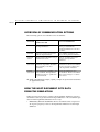
Overview of Communication Options . . . . . . . . . . . . . . . . . . . . . . . . . . . . . 18-10
How the Host Document Gets Data from the Simulation . . . . . . . . . . . . . . . . . . 18-10
Getting Data—Initiated by the Host Document . . . . . . . . . . . . . . . . . . . . . . . . 18-11
Procedure for Getting Data—Initiated by the Host Document. . . . . . . . . . . . . 18-12
Example of Getting Data—Initiated by the Host Document . . . . . . . . . . . . . . 18-12
Getting Data—Initiated by the RapidPLUS Simulation . . . . . . . . . . . . . . . . . . . 18-14
Procedure for Getting Data—Initiated by the RapidPLUS Simulation . . . . . . . . 18-15
Example of Getting Data—Initiated by the RapidPLUS Simulation . . . . . . . . . . 18-17
Sending Data to the RapidPLUS Simulation . . . . . . . . . . . . . . . . . . . . . . . . . . 18-19
Procedure for Sending Data . . . . . . . . . . . . . . . . . . . . . . . . . . . . . . . . . 18-19
Example of Sending Data . . . . . . . . . . . . . . . . . . . . . . . . . . . . . . . . . . . 18-20
xiii
Sending External Actions to the RapidPLUS Simulation . . . . . . . . . . . . . . . . . . . 18-22
Modifying the Rapid Simulator to Accept External Actions . . . . . . . . . . . . . . . 18-23
Modifying the Host Document to Send External Actions . . . . . . . . . . . . . . . . 18-23
Setting the Rapid Simulator’s Routing Mode . . . . . . . . . . . . . . . . . . . . . . . . . . 18-24
Setting the Routing Mode . . . . . . . . . . . . . . . . . . . . . . . . . . . . . . . . . . . 18-25
Monitoring User Actions in the RapidPLUS Simulation . . . . . . . . . . . . . . . . . . . . 18-26
Getting User Actions from the Simulation . . . . . . . . . . . . . . . . . . . . . . . . . 18-26
Modifying the Host Document to Monitor User Actions . . . . . . . . . . . . . . . . 18-27
Displaying User Actions in the Host Document . . . . . . . . . . . . . . . . . . . . . . 18-28
Rerouting User Actions . . . . . . . . . . . . . . . . . . . . . . . . . . . . . . . . . . . . . . . 18-29
Modifying the Host Document to Respond to User Actions . . . . . . . . . . . . . . . 18-30
Controlling the Rapid Recorder . . . . . . . . . . . . . . . . . . . . . . . . . . . . . . . . 18-32
Controlling the RapidPLUS Simulation’s State . . . . . . . . . . . . . . . . . . . . . . . 18-33
Communicating with DDE Objects . . . . . . . . . . . . . . . . . . . . . . . . . . . . . 18-33
Properties, Methods, and Events . . . . . . . . . . . . . . . . . . . . . . . . . . . . . . . . . 18-34
Properties . . . . . . . . . . . . . . . . . . . . . . . . . . . . . . . . . . . . . . . . . . . . . 18-34
Methods. . . . . . . . . . . . . . . . . . . . . . . . . . . . . . . . . . . . . . . . . . . . . . 18-38
Events . . . . . . . . . . . . . . . . . . . . . . . . . . . . . . . . . . . . . . . . . . . . . . . 18-46
C H A P T E R 1 9 : U S I N G J A V A B E A N S I N R A P I D P L U S . . . . . . . . . . . . . . . . . .19-1
Integrating JavaBean Objects into RapidPLUS . . . . . . . . . . . . . . . . . . . . . . . . . .19-2
The Search Path for JavaBean Objects . . . . . . . . . . . . . . . . . . . . . . . . . . . . .19-2
Adding a JavaBean to RapidPLUS . . . . . . . . . . . . . . . . . . . . . . . . . . . . . . . .19-3
Registering a JavaBean in RapidPLUS . . . . . . . . . . . . . . . . . . . . . . . . . . . . .19-4
Windowed vs. Non-Windowed JavaBean Objects . . . . . . . . . . . . . . . . . . . . . .19-4
Logic for JavaBean Objects . . . . . . . . . . . . . . . . . . . . . . . . . . . . . . . . . . . . . .19-6
Supported JavaBean Types . . . . . . . . . . . . . . . . . . . . . . . . . . . . . . . . . . . .19-7
Properties . . . . . . . . . . . . . . . . . . . . . . . . . . . . . . . . . . . . . . . . . . . . . .19-9
Functions . . . . . . . . . . . . . . . . . . . . . . . . . . . . . . . . . . . . . . . . . . . . . 19-10
Events . . . . . . . . . . . . . . . . . . . . . . . . . . . . . . . . . . . . . . . . . . . . . . . 19-11
Using the BeanInfo Class to Define the Logic Interface of JavaBeans . . . . . . . . . 19-12
Checking the Running Status of JavaBean Objects . . . . . . . . . . . . . . . . . . . . . . . 19-13
Step 1: Implement BeanContextChild . . . . . . . . . . . . . . . . . . . . . . . . . . . . 19-13
Step 2: Supply a BeanContext Object to Query Status . . . . . . . . . . . . . . . . . . 19-13
C O N T E N T S
xiv
Implementing Recordable Events for JavaBean Objects . . . . . . . . . . . . . . . . . . . 19-14
Step 1: Implement RapidAccessible . . . . . . . . . . . . . . . . . . . . . . . . . . . . . 19-14
Step 2: Use the Helper Class, RapidRoutingSupport . . . . . . . . . . . . . . . . . . . 19-15
Step 3: Implement Event Recording . . . . . . . . . . . . . . . . . . . . . . . . . . . . 19-16
Step 4: Implement injectRoutableValue . . . . . . . . . . . . . . . . . . . . . . . . . . 19-17
Step 5: Compare the Recordable and Nonrecordable JavaBean Objects . . . . . . . 19-18
Debugging JavaBean Objects . . . . . . . . . . . . . . . . . . . . . . . . . . . . . . . . . . . 19-18
Using the Java Console . . . . . . . . . . . . . . . . . . . . . . . . . . . . . . . . . . . . 19-19
JavaBean Incompatibility . . . . . . . . . . . . . . . . . . . . . . . . . . . . . . . . . . . 19-19
Debugging Java Code Running Inside RapidPLUS . . . . . . . . . . . . . . . . . . . . 19-19
Distributing Applications with JavaBean Objects . . . . . . . . . . . . . . . . . . . . . . 19-20
Code Generation . . . . . . . . . . . . . . . . . . . . . . . . . . . . . . . . . . . . . . . . . . 19-20
C H A P T E R 2 0 : O P E N G L O B J E C T . . . . . . . . . . . . . . . . . . . . . . . . . . . . . . 20-1
Overview . . . . . . . . . . . . . . . . . . . . . . . . . . . . . . . . . . . . . . . . . . . . . . . . 20-2
Adding an OpenGL Object to the Object Layout . . . . . . . . . . . . . . . . . . . . . . . . 20-3
Setting the Object’s Parameters . . . . . . . . . . . . . . . . . . . . . . . . . . . . . . . . 20-3
About Your OpenGL and GLU DLLs . . . . . . . . . . . . . . . . . . . . . . . . . . . . . 20-5
Editing Colors . . . . . . . . . . . . . . . . . . . . . . . . . . . . . . . . . . . . . . . . . . 20-5
Adding Quadric and Tessellator Data Objects . . . . . . . . . . . . . . . . . . . . . . . . 20-6
Implementing in the Application Logic . . . . . . . . . . . . . . . . . . . . . . . . . . . . . 20-6
OpenGL Functions and Constants in RapidPLUS Syntax . . . . . . . . . . . . . . . . . 20-6
Initializing and Using Quadric and Tessellator Data Objects . . . . . . . . . . . . . . . 20-9
Error Handling . . . . . . . . . . . . . . . . . . . . . . . . . . . . . . . . . . . . . . . . . . 20-9
Implementing Raster Images . . . . . . . . . . . . . . . . . . . . . . . . . . . . . . . . . 20-10
Implementing WGL Functions . . . . . . . . . . . . . . . . . . . . . . . . . . . . . . . 20-11
Drawing Text . . . . . . . . . . . . . . . . . . . . . . . . . . . . . . . . . . . . . . . . . . 20-11
Code Generation . . . . . . . . . . . . . . . . . . . . . . . . . . . . . . . . . . . . . . . . . . 20-12
C H A P T E R 2 1 : G R A P H I C O B J E C T S T A C K O R D E R . . . . . . . . . . . . . . . . . . 21-1
Changing Stack Order in the Object Layout . . . . . . . . . . . . . . . . . . . . . . . . . . . 21-2
Bringing In Front Of or Sending To Back Of . . . . . . . . . . . . . . . . . . . . . . . . 21-2
Changing Stack Order During Runtime. . . . . . . . . . . . . . . . . . . . . . . . . . . . . . 21-3
Moving Dynamic Graphic Objects to Front or Back . . . . . . . . . . . . . . . . . . . . 21-3
Using the orderPosition Property to Change Stack Order . . . . . . . . . . . . . . . . . 21-4
xv
C H A P T E R 2 2 : U S E R O B J E C T S W I T H M E S S A G E S . . . . . . . . . . . . . . . . . . .22-1
How Does a User Object Message Work? . . . . . . . . . . . . . . . . . . . . . . . . . . . . .22-2
User Object Message Parts: A Glossary . . . . . . . . . . . . . . . . . . . . . . . . . . . . . . .22-4
Adding Messages to a User Object . . . . . . . . . . . . . . . . . . . . . . . . . . . . . . . . .22-5
Adding Unions and Structures . . . . . . . . . . . . . . . . . . . . . . . . . . . . . . . . .22-7
Adding Fields to a Structure . . . . . . . . . . . . . . . . . . . . . . . . . . . . . . . . . . .22-9
Editing Fields and Changing Names . . . . . . . . . . . . . . . . . . . . . . . . . . . . . 22-12
Deleting a Field, Structure, or Union . . . . . . . . . . . . . . . . . . . . . . . . . . . . 22-13
Changing the Order of Unions, Structures, and Fields . . . . . . . . . . . . . . . . . . 22-13
Defining the Memory Allocation Method . . . . . . . . . . . . . . . . . . . . . . . . . 22-13
When to Use an Array of Structures . . . . . . . . . . . . . . . . . . . . . . . . . . . . . 22-14
Using the User Object Message Logic . . . . . . . . . . . . . . . . . . . . . . . . . . . . . . . 22-15
Message Properties, Functions, Conditions, and Events . . . . . . . . . . . . . . . . . 22-17
Using Arrays of Structures in Logic . . . . . . . . . . . . . . . . . . . . . . . . . . . . . . 22-20
Runtime Errors . . . . . . . . . . . . . . . . . . . . . . . . . . . . . . . . . . . . . . . . . . 22-20
Examples of Usage . . . . . . . . . . . . . . . . . . . . . . . . . . . . . . . . . . . . . . . 22-21
Using Messages As Data Containers . . . . . . . . . . . . . . . . . . . . . . . . . . . . . . . 22-22
Importing Structures from a File . . . . . . . . . . . . . . . . . . . . . . . . . . . . . . . . . 22-24
Importing a Structure . . . . . . . . . . . . . . . . . . . . . . . . . . . . . . . . . . . . . . 22-26
How RapidPLUS Handles Various Items during Translation . . . . . . . . . . . . . . . 22-28
C H A P T E R 2 3 : S T A T E M A T R I X . . . . . . . . . . . . . . . . . . . . . . . . . . . . . . . .23-1
Overview . . . . . . . . . . . . . . . . . . . . . . . . . . . . . . . . . . . . . . . . . . . . . . . .23-2
Exporting Logic Data . . . . . . . . . . . . . . . . . . . . . . . . . . . . . . . . . . . . . . . . .23-3
C H A P T E R 2 4 : E X P O R T I N G S T A T E C H A R T S T O V I S I O . . . . . . . . . . . . . . .24-1
Overview . . . . . . . . . . . . . . . . . . . . . . . . . . . . . . . . . . . . . . . . . . . . . . . .24-2
Exporting a State Chart . . . . . . . . . . . . . . . . . . . . . . . . . . . . . . . . . . . . . . . .24-4
Choosing and Creating Schemes for Exported State Charts . . . . . . . . . . . . . . . .24-6
C O N T E N T S
xvi
CHAPTER 25: GENERATING REPORTS
. . . . . . . . . . . . . . . . . . . . . . . . . 25-1
Overview of the RapidPLUS Reports . . . . . . . . . . . . . . . . . . . . . . . . . . . . . . . . 25-2
Working with Reports in the Report Viewer . . . . . . . . . . . . . . . . . . . . . . . . . . . 25-3
Viewing Reports . . . . . . . . . . . . . . . . . . . . . . . . . . . . . . . . . . . . . . . . . 25-4
Saving Reports . . . . . . . . . . . . . . . . . . . . . . . . . . . . . . . . . . . . . . . . . . 25-4
Printing Reports . . . . . . . . . . . . . . . . . . . . . . . . . . . . . . . . . . . . . . . . . 25-4
Editing Reports . . . . . . . . . . . . . . . . . . . . . . . . . . . . . . . . . . . . . . . . . . 25-5
Object Reports . . . . . . . . . . . . . . . . . . . . . . . . . . . . . . . . . . . . . . . . . . . . . 25-5
Object Layout Report . . . . . . . . . . . . . . . . . . . . . . . . . . . . . . . . . . . . . . 25-5
Object Tree Report . . . . . . . . . . . . . . . . . . . . . . . . . . . . . . . . . . . . . . . . 25-6
Object Data Report . . . . . . . . . . . . . . . . . . . . . . . . . . . . . . . . . . . . . . . 25-7
Prototyper Layout Report . . . . . . . . . . . . . . . . . . . . . . . . . . . . . . . . . . . . 25-9
Mode Reports . . . . . . . . . . . . . . . . . . . . . . . . . . . . . . . . . . . . . . . . . . . . 25-10
State Chart Plot . . . . . . . . . . . . . . . . . . . . . . . . . . . . . . . . . . . . . . . . . 25-10
Mode Tree Report . . . . . . . . . . . . . . . . . . . . . . . . . . . . . . . . . . . . . . . 25-12
Mode Data Report . . . . . . . . . . . . . . . . . . . . . . . . . . . . . . . . . . . . . . . 25-13
User Object Interface Reports . . . . . . . . . . . . . . . . . . . . . . . . . . . . . . . . . . . 25-15
Project Component Reports . . . . . . . . . . . . . . . . . . . . . . . . . . . . . . . . . . . 25-17
Component Dependency Tree Report . . . . . . . . . . . . . . . . . . . . . . . . . . . . 25-17
Component List Report . . . . . . . . . . . . . . . . . . . . . . . . . . . . . . . . . . . . 25-18
Detailed Component List Report . . . . . . . . . . . . . . . . . . . . . . . . . . . . . . 25-19
Target Graphic Displays Report . . . . . . . . . . . . . . . . . . . . . . . . . . . . . . . 25-19
Coverage Test Reports . . . . . . . . . . . . . . . . . . . . . . . . . . . . . . . . . . . . . . . 25-20
XML Reports . . . . . . . . . . . . . . . . . . . . . . . . . . . . . . . . . . . . . . . . . . . . . 25-22
Generating an XML Report. . . . . . . . . . . . . . . . . . . . . . . . . . . . . . . . . . 25-23
Understanding the XML Reports . . . . . . . . . . . . . . . . . . . . . . . . . . . . . . 25-24
RapidPLUS Object Elements and Their Nested Tags . . . . . . . . . . . . . . . . . . . 25-25
Mode Elements and Their Nested Tags . . . . . . . . . . . . . . . . . . . . . . . . . . . 25-30
Logic-Related Elements . . . . . . . . . . . . . . . . . . . . . . . . . . . . . . . . . . . . 25-31
Following the Path from a Mode to Its Logic . . . . . . . . . . . . . . . . . . . . . . . 25-33
xvii
C H A P T E R 2 6 : O B J E C T E N H A N C E M E N T S . . . . . . . . . . . . . . . . . . . . . . . . .26-1
One-Dimensional Arrays . . . . . . . . . . . . . . . . . . . . . . . . . . . . . . . . . . . . . . .26-2
Searching Backwards . . . . . . . . . . . . . . . . . . . . . . . . . . . . . . . . . . . . . . .26-2
Data Stores and Arrays . . . . . . . . . . . . . . . . . . . . . . . . . . . . . . . . . . . . . . . .26-4
Reading Unicode Strings . . . . . . . . . . . . . . . . . . . . . . . . . . . . . . . . . . . . .26-4
Sorting Data Stores and Arrays . . . . . . . . . . . . . . . . . . . . . . . . . . . . . . . . .26-4
Two-Dimensional Arrays: Extended Functionality . . . . . . . . . . . . . . . . . . . . . . . .26-8
Usage Examples . . . . . . . . . . . . . . . . . . . . . . . . . . . . . . . . . . . . . . . . . 26-13
Changes to Assign and loadFromFile: Functions . . . . . . . . . . . . . . . . . . . . . . 26-17
Commlink Object . . . . . . . . . . . . . . . . . . . . . . . . . . . . . . . . . . . . . . . . . . 26-17
Input/Output by Byte . . . . . . . . . . . . . . . . . . . . . . . . . . . . . . . . . . . . . 26-17
Three-Segment Pointer . . . . . . . . . . . . . . . . . . . . . . . . . . . . . . . . . . . . . . . 26-19
DLL Object . . . . . . . . . . . . . . . . . . . . . . . . . . . . . . . . . . . . . . . . . . . . . . 26-21
Pushbutton Object . . . . . . . . . . . . . . . . . . . . . . . . . . . . . . . . . . . . . . . . . . 26-22
Text Display Object . . . . . . . . . . . . . . . . . . . . . . . . . . . . . . . . . . . . . . . . . 26-22
C H A P T E R 2 7 : A D D I T I O N A L R A P I D P L U S E N H A N C E M E N T S . . . . . . . . . . .27-1
Multiple Tool Enhancements . . . . . . . . . . . . . . . . . . . . . . . . . . . . . . . . . . . .27-6
Back and Forward Buttons: Retracing Mode Selections . . . . . . . . . . . . . . . . . . .27-6
Undo/Redo . . . . . . . . . . . . . . . . . . . . . . . . . . . . . . . . . . . . . . . . . . . . .27-6
Application Manager . . . . . . . . . . . . . . . . . . . . . . . . . . . . . . . . . . . . . . . . .27-8
Changing RapidPLUS Fonts . . . . . . . . . . . . . . . . . . . . . . . . . . . . . . . . . . .27-8
Saving Current Settings . . . . . . . . . . . . . . . . . . . . . . . . . . . . . . . . . . . . .27-9
Object Layout . . . . . . . . . . . . . . . . . . . . . . . . . . . . . . . . . . . . . . . . . . . . . .27-9
Modification to the Rules for Naming Objects . . . . . . . . . . . . . . . . . . . . . . . .27-9
Selecting Objects from a List . . . . . . . . . . . . . . . . . . . . . . . . . . . . . . . . . 27-10
Importing Bitmap Files . . . . . . . . . . . . . . . . . . . . . . . . . . . . . . . . . . . . . 27-11
User Object Properties Dialog Box . . . . . . . . . . . . . . . . . . . . . . . . . . . . . . 27-11
Using Constant Set Properties . . . . . . . . . . . . . . . . . . . . . . . . . . . . . . . . . 27-13
C O N T E N T S
xviii
Logic Editor . . . . . . . . . . . . . . . . . . . . . . . . . . . . . . . . . . . . . . . . . . . . . 27-16
Color Coding in the Logic Editor . . . . . . . . . . . . . . . . . . . . . . . . . . . . . . 27-16
Declaring Local Variables . . . . . . . . . . . . . . . . . . . . . . . . . . . . . . . . . . . 27-16
Execution of Mode Activities . . . . . . . . . . . . . . . . . . . . . . . . . . . . . . . . 27-18
User Functions: Limit on Number of Objects . . . . . . . . . . . . . . . . . . . . . . . 27-19
User Functions: Returning Specified Values . . . . . . . . . . . . . . . . . . . . . . . . 27-20
Viewing Values of Local Variables and User Function Arguments. . . . . . . . . . . 27-23
Object Editor . . . . . . . . . . . . . . . . . . . . . . . . . . . . . . . . . . . . . . . . . . . . 27-24
Cursor Coordinates Status Box . . . . . . . . . . . . . . . . . . . . . . . . . . . . . . . 27-24
Pasting Bitmaps into the Object Editor . . . . . . . . . . . . . . . . . . . . . . . . . . 27-24
C H A P T E R 2 8 : A P P L I C A T I O N P A C K A G E R . . . . . . . . . . . . . . . . . . . . . . . . 28-1
Building an Application Package . . . . . . . . . . . . . . . . . . . . . . . . . . . . . . . . . . 28-2
Step 1: Setting Up the Application Packager . . . . . . . . . . . . . . . . . . . . . . . . 28-3
Step 2: Selecting the Application and Files to Package . . . . . . . . . . . . . . . . . . 28-4
Step 3: Selecting Destination Folders/Building the Package . . . . . . . . . . . . . . . 28-8
Editing a Package . . . . . . . . . . . . . . . . . . . . . . . . . . . . . . . . . . . . . . . . . . 28-10
Editing a PAK File in the Application Packager . . . . . . . . . . . . . . . . . . . . . . 28-10
Editing a PAK File Without Opening the Application Packager . . . . . . . . . . . . 28-10
Distributing and Using a Packaged Application . . . . . . . . . . . . . . . . . . . . . . . . 28-11
A P P E N D I X A : R A P I D P L U S S E A R C H P A T H S . . . . . . . . . . . . . . . . . . . . . . . A-1
INDEX
. . . . . . . . . . . . . . . . . . . . . . . . . . . . . . . . . . . . . . . . . . . . . . INDEX-1
xix
ABOUT THE RAPIDPLUS DOCUMENTATION
About the User Manual Supplement
This manual provides the information you need to use the new objects and
features added since Rapid 4.0. It supplements the information found in the
Rapid User Manual.
•
Chapter 1: “Managing Projects” describes how to work with RapidPLUS on
a project-wide basis (simultaneously editing the parent application and its
user objects). It also describes how to implement team development and
version control using XML application files.
•
Chapter 2: “RapidPLUS Applications in XML” explains how to work with
applications saved to XML format and the benefits of working with
projects in XML.
•
Chapter 3: “Comparing Applications in the Differencing Tool” explains
how to use the Differencing Tool to compare objects, modes, user objects,
and/or interface of two applications.
•
Chapter 4: “Debugging Applications” describes how to filter and capture
the Debugger output in a log that can be viewed, saved, and printed.
•
Chapter 5: “Logic Error View” describes how this tool displays errors and
warnings for logic and XML applications.
•
Chapter 6: “Pasting Operations” explains how to cut/copy and paste
objects, modes, and logic elements between RapidPLUS applications.
•
Chapter 7: “Writing Logic Using Loops and Branches” describes how to
use loop statements to execute a block (i.e., a set of activities) over and
over again, and how to use branch statements to execute a block when
specified conditions are satisfied.
•
Chapter 8: “Find and Replace” explains how to search for and replace
strings in the application logic and logic references to specific objects.
•
Chapter 9: “Verification Test” explains how to run a verification test to
perform a basic check on an application’s logic design.
•
Chapter 10: “Nongraphic Objects” describes how to work with nongraphic
objects in the Object Layout. It describes the nongraphic objects in the
data, time, and signal classes and system objects.
•
Chapter 11: “Constant Objects” describes how to define and use this class
of data objects whose values are defined in the Object Layout and cannot
be changed dynamically during runtime. Constant objects are generated as
#define and enum statements.
xx
•
Chapter 12: “Graphic Displays” describes how to add and define a graphic
display object/graphic display-true color in the Object Layout and define
its logic. The graphic display works in conjunction with the font object
and with bitmap objects. Topics covered include working with the object’s
colors, working with text and bitmaps, and various drawing modes. This
chapter also details how to use graphic display buffers to extend the
object’s functionality.
•
Chapter 13: “Bitmap, Image, and Font Objects” teaches how to define
bitmap, image, and font objects in the Object Layout and Logic Editor.
Bitmaps and images are used to enhance the visual appeal of simulations
and make them more realistic. In simulations that have a graphic display,
bitmaps and images—together with text strings and font objects—play an
essential part; they constitute the content to be presented on the graphic
display.
•
Chapter 14: “Touch Screen Object” describes how to incorporate a touch
screen into a RapidPLUS application.
•
Chapter 15: “Database Access Object” presents an object that links the
RapidPLUS application to any database that supports the ODBC (Open
Database Connectivity) driver (version 2.0 or higher). In the Object
Layout, you define the link parameters and build an initial SQL (Structured
Query Language) statement to retrieve the desired records from the
database. The resulting query result table is available to all objects in the
RapidPLUS application. The SQL statement can be changed and the query
rerun dynamically during runtime. Depending on the nature of the link, it
is also possible to add, delete, and modify records in the database itself.
•
Chapter 16: “Applink Object” describes how to use the Applink object to
enable RapidPLUS applications to communicate with external applications
via shared memory.
•
Chapter 17: “Using ActiveX Controls” describes how to add, register, and
use ActiveX controls as objects in RapidPLUS applications.
•
Chapter 18: “Hosting RapidPLUS Simulations in Windows Programs”
describes how to use the RapidPLUS Simulator ActiveX object to link or
embed the Rapid Reviewer in a Windows program so that the Windows
program can manipulate and control a RapidPLUS application.
•
Chapter 19: “Using JavaBeans in RapidPLUS” describes how to add,
register, and use JavaBeans as objects in RapidPLUS applications.
•
Chapter 20: “OpenGL Object” describes how to use the OpenGL object to
implement complex graphic objects in RapidPLUS applications. OpenGL is
a platform-independent graphics language that supports the fast rendering
of 2-D and 3-D graphics.
xxi
•
Chapter 21: “Graphic Object Stack Order” explains how to control the
graphic object stack order (Z-order) in both the Object Layout at design
time and in the Prototyper at runtime.
•
Chapter 22: “User Objects with Messages” provides detailed information
about how a user object message works, how to build a user object message
and use its logic, how to use data containers, and how to import a message
structure from a header file.
•
Chapter 23: “State Matrix” explains how to export logic data to Microsoft
Excel. The exported data appears in Excel’s workbook format (XLS). A
RapidPLUS application’s state matrix enables you to systematically check
the application’s modes, triggers, and transitions.
•
Chapter 24: “Exporting State Charts to Visio” explains how to export a
state chart to Microsoft Visio. The exported chart follows the UML
conventions for state charts.
•
Chapter 25: “Generating Reports” explains the various reports that
can be generated for objects, modes, user object interface, and project
components. It also describes XML reports that can be generated, and the
API for these reports.
•
Chapter 26: “Object Enhancements” provides detailed descriptions of the
new functionality that has been added to existing RapidPLUS objects, such
as holders, arrays, strings, integers, and DLLs.
•
Chapter 27: “Additional RapidPLUS Enhancements” introduces new
features and enhancements of existing features.
•
Chapter 28: “Application Packager” describes this distribution utility,
which is used for packaging a RapidPLUS application and its supporting
files.
•
Appendix A: “RapidPLUS Search Paths” lists the paths that RapidPLUS
searches for files.
Conventions Used in This Manual
The RapidPLUS documentation uses the following conventions:
•
“Choose File|Save Application” means to select the Save Application
command from the File menu.
•
Names of properties, functions and events are italicized:
idReceived property, checkForData function, dataReceived event
xxii
•
•
File names are italicized:
main.c
Complete phrases of RapidPLUS logic are presented in bold, sans serif font:
& Switch2.position3 is connected
New in
version 8.0
•
In Chapter 27: “Additional RapidPLUS Enhancements,” features that are
new in version 8.0 are marked in the tables that appear at the beginning of
the chapter.
RapidPLUS Help
RapidPLUS offers you Help on procedures, menu commands, dialog boxes and
object properties and functions. You can open Help by choosing Help|Rapid
Help Topics in any of the RapidPLUS windows.
All of the RapidPLUS dialog boxes have a Help button, allowing you to get
explanations on how to use the dialog box.
You can also get context-sensitive Help on a particular item (button, menu
command, etc.,) by clicking the Help button in the tool bar and then clicking
the item.
❖ NOTES: To get Help on a menu command or on a function in the Logic Palette,
you can also highlight the command or function (with the mouse or using the
keyboard arrow keys) and press F1.
1-1
C
H
A
P
T
E
R
1
Managing Projects
The main RapidPLUS application (the RPD file) typically includes multiple
user objects (the UDO files), which themselves often contain other user
objects. Each user object is an autonomous unit, which exists independently
of the applications that include it. When editing affects the interface of the
user object to its parent application, RapidPLUS automatically updates the
interface and reverifies the logic.
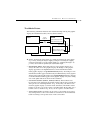
In this chapter, we use the following terminology:
A project is a RapidPLUS application (RPD or UDO file) that includes user
objects.
Project components are all the applications that make up the project, i.e., the
RPD file and each of its UDO files.
Main application is used exclusively to refer to the RPD file.
RXD and UXO files are RPD and UDO files that were generated to XML
format.
This chapter presents:
•
What happens during the automatic interface update and logic
reverification.
•
How to switch among project components.
•
How to edit project components within the parent application.
•
How to replace and rename user objects in a project.
•
How to apply various operations to an entire project.
M A N A G I N G
P R O J E C T S
1-2
•
How to use the Properties option to keep track of changes in the
application.
•
How to add notes to modes and objects.
•
The RapidPLUS search path.
•
How to implement team development and version control using XML
application files (RXD and UXO files).
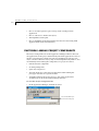
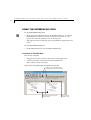
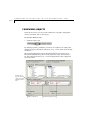
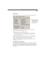
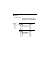
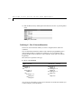
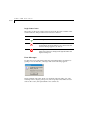
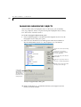
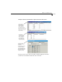
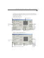
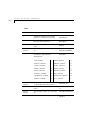
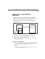
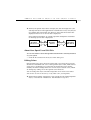
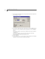
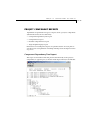
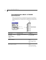
SWITCHING AMONG PROJECT COMPONENTS
The Project Components list in the Application Manager window shows all
the applications in the project hierarchically. The main application is first on
the list. It is followed by all the user objects in alphabetical order. If a user
object contains other user objects, they are listed alphabetically under it. You
can manually switch among the components of a project in order to:
•
Edit the selected component.
•
Set debug breakpoints.
•
Open object inspectors.
•
View the mode tree of the selected component when running the
prototyper with the trace option enabled.
•
Add linked items from any user object to the parent application’s
document layout in the Document Manager window.
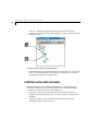
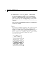
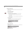
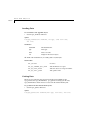
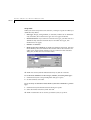
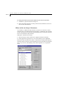
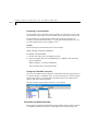
To view the Project Components list:
•
In the Application Manager, click the list arrow:
Access hierarchical list, as
shown on the next page
S W I T C H I N G
A M O N G
P R O J E C T
C O M P O N E N T S
1-3
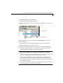
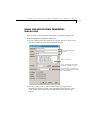
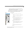
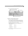
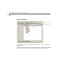
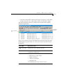
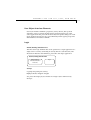
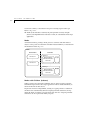
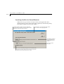
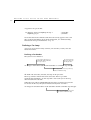
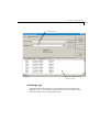
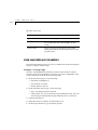
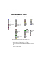
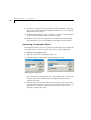
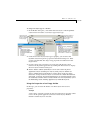
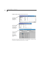
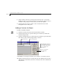
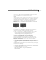
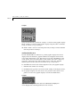
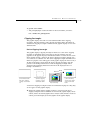
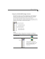
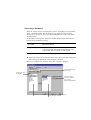
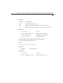
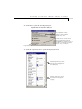
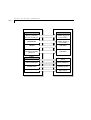
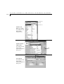
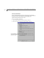
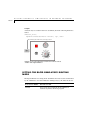
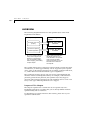
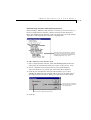
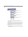
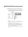
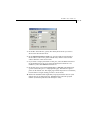
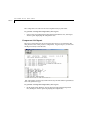
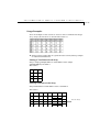
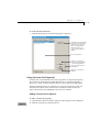
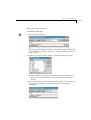
To switch among project components:
1 Click the Project Components list arrow.
2 Select the desired user object from the Project Components list, as shown
below.
The main application
User objects in alphabetical
and hierarchical order
Full paths to the user object files
While debugging an application, RapidPLUS automatically switches user
object views when:
•
Stepping into an exported function called by the parent application.
•
Hitting a breakpoint set in the user object.
❖ NOTE: The Prototyper window is always dedicated to the parent application
regardless of which user object is currently active or how it became so (either
automatically during debugging or by manual switching).
Switching components while the Prototyper is running
Project components cannot be edited while the Prototyper is running. Any
editing of a component automatically stops the Prototyper.
If the Prototyper is running, and you select a project component that is
not already in edit mode, the selected component opens in read-only
mode. This is indicated by the Edit button next to the Project Components
list becoming available.
If you click the Edit button, the selected component opens in edit mode,
and only then does the Prototyper stop running.
M A N A G I N G
P R O J E C T S
1-4
OPENING A PROJECT
When you open an application, RapidPLUS treats it as a project. It scans the
interfaces of all the components to see if any updates are required. Updates
are needed when changes made in the individual components affect their
interfaces to the parent applications (refer to “Changing a User-Defined
Object that is Part of an Application” on p. 19-21 of the Rapid User Manual).
When RapidPLUS detects mismatches, it automatically updates the interface.
Mismatches that generated error messages are available in a report that you
can print and save.
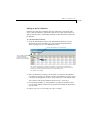
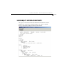
Automatic Interface Updates
RapidPLUS uses the following rules to make the needed interface changes in
the parent application:
•
Exported properties and functions that exist in the user object interface to
the parent application, but not in the user object, are removed from the
interface. The logic is re-evaluated and, where necessary, commented out.
Otherwise, this process is transparent to the user.
•
Exported properties, events, and functions that were modified in the user
object, but not in its interface to the parent application, are removed from
the interface and replaced by new same-type, same-name objects (i.e.
properties, events, and functions).
•
Functions with the same name in both the user object and its interface to
the parent application, but with different argument types, are modified so
that the argument types in the interface match those in the user object.
•
Messages (unions) are processed recursively down to their fields. The fields
receive the same treatment as exported properties.
•
New exported properties and functions, that do not exist in the user
object’s interface to the parent application, are added to the interface.
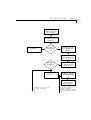
Automatic Interface Logic Reverification
An application needs logic reverification when an update involves the
removal or change of properties or functions. Invalid logic is displayed in the
Logic Error View, where you can double-click any line to open it in the Logic
Editor. In the Logic Error View window, the lines of invalid logic are grouped
by user objects, and the user objects are listed alphabetically.
O P E N I N G
A
P R O J E C T
1-5
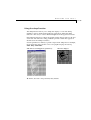
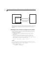
Missing or Defective User Objects
A project that is missing one or more user objects, or contains a defective
graphic user object, can be opened. When it is first opened, the Logic Error
View opens notifying you that the user object is missing.
A missing graphic user object appears as a crossed-out rectangle in the Object
Layout. This rectangle will also appear in state transition charts, and in
Document Manager documents. A missing/defective graphic user object can
be manipulated on the layout and in the logic like any other graphic object,
however, it cannot be manipulated like a user object. In other words, it is
not listed in the Project Components list and it has no interface. More
importantly, it will cause a fatal runtime error when you run the application
in the Prototyper.
A missing or defective nongraphic user object appears in the Nongraphic
Objects dialog box, but also cannot be manipulated like a user object.
Examples of Usage
Adding a Property or Function to a User Object
You have a project with many instances of EDITOR.UDO in its components.
You edit EDITOR.UDO by adding to it several new properties and functions.
When you open the main application after editing EDITOR.UDO, RapidPLUS
automatically includes the new properties and functions in all the relevant
interfaces, and you can immediately proceed to use them in the Logic Editor.
Renaming a Property in a User Object
You have an application with many instances of BUTTON.UDO. The user
object has two properties, width and height, that control the size of the button.
These properties are used in many places throughout the project, whenever
the button user object is used.
You now want to add an optional bitmap on the button and allow control of
the bitmap size. You therefore add two new properties to the user object:
bitmap_width and bitmap_height and, to avoid any confusion, you change the
names of the button size properties from width and height to button_width and
button_height, respectively. As a result, all the logic that uses the button size
properties becomes invalid.
RapidPLUS automatically updates all the interfaces of the button user object,
and lists all the errors involving the width and height properties in the Logic
M A N A G I N G
P R O J E C T S
1-6
Error View. You can now use project-wide Find & Replace to substitute
button_width for width and button_height for height.
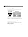
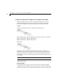
Changing the Definition of an Exported Function
You have an application with many instances of UDO1.UDO. This user object
has one exported function called dialNumber that receives an integer
argument. The function is defined as follows:
dialNumber: <Integer: phoneNumber>
You now decide that the phone number should accept characters as well as
digits. You therefore change the exported property dialNumber in UDO1.UDO
as follows:
dialNumber: <string: phoneNumber>
The logic is still valid because the string argument accepts integers, so the
application is automatically corrected when it is next opened.
If the change in the function affects its type (for example, you changed the
argument type from a string to an integer, or you added an argument to the
function), the change is automatically applied the next time the application is
opened, and all the lines that have become invalid as a result of the change
are listed in the Logic Error View window.
Adding Arguments to a Function
In your application you use the user object LAMPS.UDO. This user object has a
function called setShape: <Integer>, which receives an integer argument. You
decide to change the function so that it will receive an additional argument
for the color of the lamps. Now the function is defined as setShape: <Integer>
color: <Integer>. As a result, all calls to this function throughout the project
become invalid.
When you open the main application, all the interfaces of LAMPS.UDO to its
parent applications are automatically updated. All logic errors resulting from
the modifications in the function throughout the project appear in the Logic
Error View window. You still have to correct each logic line manually, but all
the errors from the entire project are grouped together.
E D I T I N G
P R O J E C T
C O M P O N E N T S
1-7
EDITING PROJECT COMPONENTS
You can edit any component from the Project Components list.
To edit a project component:
1 Click the Project Components list to open it.
2 Select a component from the list. All of the open RapidPLUS tools display
the selected component.
When editing affects a component’s interface to its parent application,
RapidPLUS will automatically update the interface as described in
“Opening a Project” on p. 1-4. The update process is launched in the
following cases:
•
When you select a different component from the Project Components
list.
•
When you start the Prototyper.
•
When you save the application.
•
When you start the Code Generator.
Invalid logic is displayed in the Logic Error View window.
REPLACING AND RENAMING USER OBJECTS
You can replace one user object by another. You can also use this option to
rename user objects.
❖ NOTE: You cannot replace nor rename the main application. You can however
use the Save as option to create the main application with a different name.
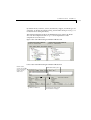
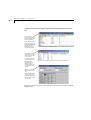
Replacing a User Object
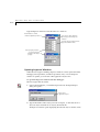
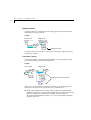
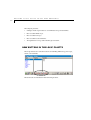
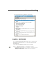
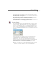
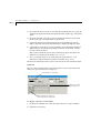
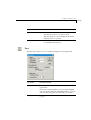
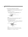
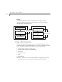
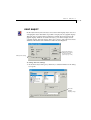
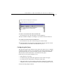
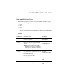
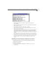
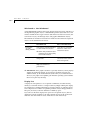
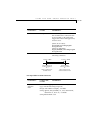
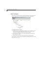
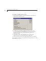
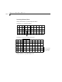
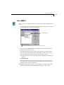
To replace a user object:
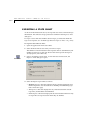
1 Choose File|Advanced|Replace User Object; the Replace User Object dialog
box opens.
M A N A G I N G
P R O J E C T S
1-8
2 Select the user object you want to replace.
To replace: browse to select
the substitute user object
To rename: type in the new name for the user object.
Verify that a user object with this name does not already exist
3 Browse to select the substitute user object, or type its name into the box.
4 Click OK.
All the references to the original user object, in the interface to the parent
application as well as in all the relevant holders and arrays, are automatically
replaced by references to the substitute user object. The original user object is
removed from the project.
Renaming a User Object
You can also use the Replace User Object dialog box to rename a user object.
Renaming a user object is a special case of replacement where RapidPLUS first
duplicates the original user object with the new name, then uses the duplicate
to replace the original user object. As in a standard replace operation, all
references to the original user object are automatically replaced with
references to the new name, and the original user object is removed from the
project.
To rename a user object:
1 Choose File|Advanced|Replace User Object; the Replace User Object dialog
box opens.
C O M P A C T I N G
F I L E S
1-9
2 Select the user object you want to rename.
3 Type the new name in the “With user object” box. Make sure that a user
object with this name does not already exist.
4 Click OK. RapidPLUS notifies you that it was unable to locate the specified
user object, and that it will duplicate the original user object with the new
name, then use the duplicate to replace the original.
5 Click Yes to continue. The user object gets the new name.
COMPACTING FILES
When you delete an object from a RapidPLUS application (RPD or UDO file),
the space that it occupied in the file remains empty. As you subsequently add
objects to the application, RapidPLUS utilizes this empty space for the new
objects.
To eliminate empty spaces in the application file:
•
Choose File|Advanced|Compact in the Application Manager. Any
difference in file size will be seen the next time that you save the file.
❖ NOTE: You must activate this command each time you want to compact.
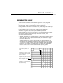
ENTIRE PROJECT VS. SINGLE COMPONENT
OPERATIONS
The Save, Compact, and Reverify Logic options have been supplemented by
the complementary options: Save All, Compact All, and Reverify Logic All.
With the new options you can save, compact, and reverify logic for the entire
project. These options also offer an easy way to upgrade RapidPLUS
applications created in earlier versions.
M A N A G I N G
P R O J E C T S
1-10
The Save, Compact, and Reverify Logic commands apply only to the currently
selected project component (the file shown in the Project Components box).
If the currently selected component is not in edit mode, the three options are
unavailable.
❖ NOTE: The three single-file operations do not apply to sub-components that are
nested in the selected component.
Reverifying Logic for an Entire Project
To reverify the logic of an entire project:
•
Choose File|Advanced|Reverify Logic All.
Compacting an Entire Project
To compact the entire project:
•
Choose File|Advanced|Compact All.
Saving an Entire Project
To save the entire project:
•
Choose File|Save All or click the Save All button.
Upgrading Applications Created in a Lower Version
When you open an application that was created in a lower version of
RapidPLUS, reverify the application’s logic, compact it, then save it. If the
application contains user objects, be sure to use the Reverify Logic All,
Compact All, and Save All commands.
U S I N G
T H E
A P P L I C A T I O N
P R O P E R T I E S
D I A L O G
B O X
1-11
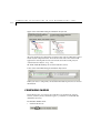
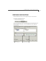
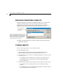
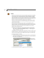
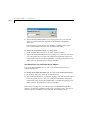
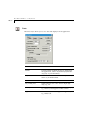
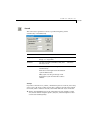
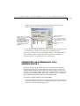
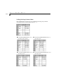
USING THE APPLICATION PROPERTIES
DIALOG BOX
This dialog box stores information that applies to RapidPLUS applications.
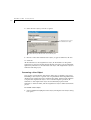
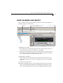
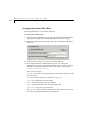
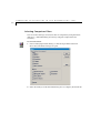
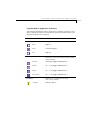
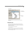
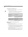
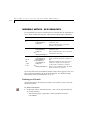
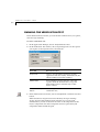
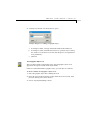
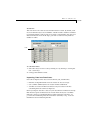
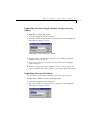
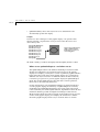
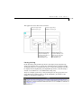
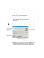
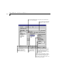
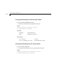
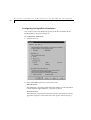
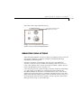
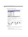
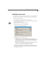
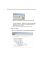
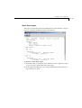
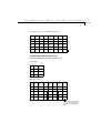
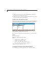
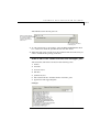
To use the Application Properties dialog box:
1 Choose File|Properties. The Application Properties dialog box opens for the
file (RPD or UDO) shown in the Components List Box.
Use for general application
information
Enter your comments
Select to automatically add comment
each time the application is loaded
Sets the application’s compilation/code
generation language and the encoding
of the XML output file
2 Use the top three boxes to enter information about the application.
Initially they display the name of the RapidPLUS application file, as well
as the logged-in user name, and company name as they appear in the
registry.
M A N A G I N G
P R O J E C T S
1-12
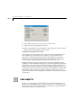
3 The revision number is automatically incremented each time the
application is loaded. When the Log check box is selected, RapidPLUS
also adds a comment each time the application is loaded.
This comment consists of the version number, the date, the time, and
the name of the logged-in user. You can edit both version number and
comments. To add your own comments, type directly into the Comments
list.
❖ TIP: We recommend that the Log check box always be selected so that
projects can be accurately compared—unless you are working with an
external version control application. For details about how this check box
affects comparisons in the Differencing Tool, see “Comparing Projects” on
p. 3-11.
4 By default, the language used for the application’s compilation and code
is the system's local language that was used when the application was
created. You can change the language in the Character set box. The
language selected will be used for the encoding of XML reports.
❖ NOTE: The automatically added log entry does not mark the file as having been
changed. The log entry is, however, saved with the properties when you save the
application.
N O T E S
O N
M O D E S
A N D
O B J E C T S
1-13
NOTES ON MODES AND OBJECTS
Notes on modes and objects are added, edited, and viewed in the Application
Manager window, as shown below:
Status bar
Add, edit, and view notes for the selected
mode or object in the notes area
Scroll through the note
To add notes to a mode:
1 In the Mode Tree, click the selected mode. The status bar below the notes
area shows the type of mode: exclusive or concurrent.
2 Type your notes in the notes area. You can adjust the size of the notes area
by resizing the Application Manager window. When typing, use the Enter
key to adjust the text to the size of the notes area.
To add notes to an object:
1 In the Object Layout, click the selected object. The status bar below the
notes area shows the type of object: flat pushbutton, square corners filled
frame, etc.
2 Proceed as in step 2 above.
❖ NOTE: In nongraphic objects, you can also add notes when you first create the
object, by clicking the Notes button in the nongraphic object dialog box. These
notes are then displayed in the notes area of the Application Manager window.
M A N A G I N G
P R O J E C T S
1-14
To edit notes:
1 Select the mode/object you want to edit. Its notes are displayed in the
notes area. The status bar shows the text: “Notes for the mode/object:”
followed by its name.
2 Edit the text in the notes area. Adjust the size of the notes area and/or use
the scroll bar buttons to navigate in it.
SEARCH PATH FOR OBJECTS
When loading applications or adding user objects (UDO) external objects
(RPX), ActiveX objects (OCX, DLL), or JavaBean objects (JAR), RapidPLUS
looks in the following locations, listed in order of priority:
•
The application folder and all its subfolders.
•
The RapidPLUS \objects folder.
•
The RapidPLUS \applics folder.
•
The RapidPLUS folder (wherever Rapidxx.exe is located).
In addition, in the development environment, the search is extended to
include the user-defined RapidPLUS search path, and in the Rapid Reviewer,
the RAPID_AUX_PATH environment variable is used.
❖ NOTE: We recommend keeping all the project files in the application folder and
its subfolders. This will simplify moving the project to a different drive or a
different computer.
Defining a Search Path
To define the RapidPLUS search path:
1 In the Application Manager, select Options|Search Path; the Rapid Search
Path dialog box opens:
S E A R C H
P A T H
F O R
O B J E C T S
1-15
2 Either type in the search path, or click Browse to select the folder. You
can define several search paths using the semi-colon as a separator (for
example: c:\my_objects;d:\objects) or just browse to another folder to
add it to the search path.
3 The search path is not saved with the application. To keep the defined
search path beyond the current session, use one of the Save Settings
options. The search path is then saved in the RapidPLUS INI file.
❖ NOTES: When the Reviewer loads an application, it does not read the
Rapidxx.ini file. However, the Reviewer does look for a RAPID_AUX_PATH
system environment variable, in which you can set a RapidPLUS search path. On
Windows NT4 systems, for example, you set environment variables via the
System icon in the Control Panel.
The RapidPLUS search path feature can be especially useful for group
development of an application. All group members would define the same search
path to the folder where the shared resources are located.
Beware of user objects with the same file name
Let’s assume that your application contains a user object instance based
on the file C:\RapidPLUS\Objects\Display.udo. Let’s also assume that, for
some reason, there is a DISPLAY.UDO (with a different interface and/or
functionality) located in your application folder.
When you load the application, RapidPLUS looks first in the application
directory, finds a DISPLAY.UDO and looks no further. Your user object
instance is now based on a different user object file than intended. If
the interfaces of the two display.udo files are not identical, RapidPLUS
will automatically perform the interface update and logic reverification
process.
Therefore, be careful about where you locate your user object files
and about giving them unique names.
M A N A G I N G
P R O J E C T S
1-16
Locating a User Object
When loading an application, RapidPLUS may be unable to locate a user
object in any of the search paths described in the preceding section “Defining
a Search Path.” In this case, a dialog box opens that prompts you to locate
the user object file.
❖ NOTE: The new path is not saved. You will have to locate the user object file
each time you open the application.
TEAM DEVELOPMENT AND VERSION
CONTROL USING XML FILES
RapidPLUS can store its components in binary format files (RPD and UDO) or
in XML format files (RXD and UXO). Using the XML format has advantages
when working with version control tools because it is a text format, which
enables comparison, merging, and editing of the files outside of RapidPLUS.
The benefits of developing RapidPLUS projects in XML format are:
•
External tools become available to the project, thereby providing greater
possiblities and flexibility for team development and version control.
•
Different versions of the same component can be compared using an
external comparison tool, including the comparison tool of the version
control system.
•
Developers can work in parallel on the same project component, merging
the changes when the work is done.
This section provides information about:
•
Checking projects or components in and out of a version control system.
•
Synchronizing component changes.
•
Comparing application and component versions.
•
Merging applications and components.
For information about the XML files , see Chapter 2: “RapidPLUS Applications
in XML.”
T E A M
D E V E L O P M E N T
A N D
V E R S I O N
C O N T R O L
U S I N G
X M L
F I L E S
1-17
Checking In/Out Projects or Components
This section presents a process for using a version control system during
RapidPLUS team development.
When setting up the project, all project files should be checked into the
version control system and should be made read-only. The project files
comprise the main application file (RXD), the user object files (UXO), and the
project settings file (CSX). Other files that should be checked in include the
shared resources (linked bitmaps, array data loaded during runtime, etc.) Also,
ActiveX and JavaBean objects should be checked in.
Developers should copy the entire release from a network folder to their local
work folder. Before working on a file, the developer must check it out of the
version control system to the work folder.
❖ TIP: If you open the main application or a user object and receive unexplained
errors in the Logic Error View window, they may be the result of changes in a
related user object. Try checking out the relevant files again.
When work is completed, developers should check in their components.
If two or more developers have worked on the same component, they should
merge their version with the latest checked-in version.
❖ RECOMMENDATION: After making all necessary changes, each developer
should compare the changed version to the checked-in version to see the changes.
When developers are working on components where the changes interact
(such as user object interface), it is important that they coordinate their
releases. Otherwise, RapidPLUS may find logic errors when opening a
component affected by another developer’s changes.
❖ TIP: If you make a change in a user object that causes logic errors in other user
objects (e.g., renaming an object that is referenced elsewhere), you should verify
the logic of the related user objects, save them, and check them in.
The project manager, who is responsible for the version build, should use a
script to check out all released files to a network folder and make the version.
The project manager should perform all the manual activities to complete the
build such as integrating the output of the external tools into the RapidPLUS
files to produce a complete working version.
When all necessary files have been checked in and merged into a valid
version, the files should be made read-only (this reduces the risk that a
developer will accidently save a file before checking it out of the version
control system). The project manager can declare a new release ready for
additional work and the developers can then copy the new release to their
working folder.
M A N A G I N G
P R O J E C T S
1-18
Recommendations for Checking In Resource Files
External resources, such as bitmaps, may be checked into the version control
system as individual files, so that developers can lock individual files and
work on them. An alternative method is to compress all the bitmaps into a
single ZIP file for easier check out. In this latter case, only one person at a time
can lock the entire set of bitmap files in order to make changes on any given
file.
For the purposes of team development and version control, we recommend
that all data for arrays and data stores be placed in external files (TXT or CSV),
which can be called using the loadFromFile: function. Both TXT and CSV
formats support change merges. Merging is more difficult for RAR and RDS file
formats.
Synchronizing Component Changes
RapidPLUS’s support for team development and version control enables
developers to synchronize changed files that were checked out from a version
control system or copied from another location—without closing the project
in RapidPLUS.
When a project component’s interface has been changed, the other
components that use its interface are affected. RapidPLUS can either mark
these components as changed or not. If they are not marked as changed,
they will not be saved unless you make direct changes in them. Because
the files are not saved, RapidPLUS will perform the automatic interface update
(as described on p. 1-4) each time the main application is opened, which adds
to the load time.
You can circumvent this process by using a command that updates the
components that are affected by a changed component.
To update components that are affected by a changed component:
1 Choose File|Advanced|Update Changed User Objects.
2 Choose File|Save All to save all the components.
Comparing Application and Component Versions
You can use a version control system, or a stand-alone XML or compare tool
to browse the differences between two versions of a RapidPLUS application or
component. Likewise you can use a directory comparison tool to compare two
lists of project components.
T E A M
D E V E L O P M E N T
A N D
V E R S I O N
C O N T R O L
U S I N G
X M L
F I L E S
1-19
Merging Applications and Components
During group development, developers may work in parallel on the same
project or even the same component. When the developers are ready to check
in their versions, they must merge the changes made on the same base
versions. The details of how to merge the versions depend on the version
control system.
In RapidPLUS XML format, every change in the application or component
affects only a single place in the file. When developers make changes in
different sections of the application or component file, there are no resulting
conflicts. In this case, most version control systems allow an automatic merge.
For example, if two developers added different objects to the same
application, the files can be merged without conflict.
There are cases, however, where developers make changes in the same
element of an application or component, resulting in a conflict during merge.
Following are examples of changes that result in merge conflicts:
•
Both developers made changes to the same line of logic.
•
One developer changed an object’s properties and the other developer
deleted the object.
•
Two developers adding elements to the same array.
In each case of conflict, someone must manually indicate which version to
keep in the merged edition.
❖ TIP: Every time you save and reopen an application or component, RapidPLUS
increases the version number, adding a line of code to the resulting XML file.
This change causes a conflict when merging application or component versions.
You can turn off the automatic version number feature in the File|Properties
dialog box. Clear the Log check box . Keep in mind that clearing the Log check
box will disable project comparisons in the Differencing Tool (but modes, objects,
user functions, and interface can still be compared). For more information, see
“Comparing Projects” on p. 3-11.
2-1
C
H
A
P
T
E
R
2
RapidPLUS Applications
in XML
RapidPLUS applications can be saved to XML format in addition to the
standard binary RapidPLUS format (RPD and UDO). The XML format offers
many development benefits:
•
Group development: the XML format can be used by configuration
management tools for check in/check out of projects, comparing versions,
and merging versions (for details, see “Team Development And Version
Control Using XML FIles” on p. 1-16).
•
Use of external tools to edit project components: XML-based or text-based
editors can be used for editing object properties and application structure.
•
Integration of third-party tools with project files: external tools can be
used for tasks such as generating reports and documents. Also RapidPLUS
application files can be created and modified by external tools.
•
Readable text files: XML application files are readable as text files without
the need to open them in RapidPLUS.
•
Ability to fix corrupted applications.
❖ CAUTION: Applications saved to XML format cannot be packaged by the
Application Packager and cannot run in the Rapid Reviewer.
This chapter presents:
•
How to save a RapidPLUS application to XML.
•
How to open a project in XML format.
•
The XML output files.
R A P I D P L U S
A P P L I C A T I O N S
I N
X M L
2-2
•
How to edit the XML application files.
•
The RapidPLUS schema file.
SAVING APPLICATIONS TO XML FORMAT
The native format for all RapidPLUS applications is the binary RPD format.
Whenever an application is saved to XML format, a corresponding RPD file
is saved in the cache, which is located in the application folder in a subfolder
named $RP_CACHE_.
❖ NOTE: After an application has been saved and opened as XML, the Save
operation maintains the XML format. To return to using the RPD format,
you must use the Save As operation.
Saving Applications and User Objects to XML
To save an application to XML:
1 Choose File|Save As.
2 In the Save As dialog box, select Rapid XML Application (*.RXD) in the
Save as type box.
3 Type in a file name, change the path if necessary, and then click Save.
The RXD file is written to the specified folder and the RPD file is written in
the cache.
If the application has user objects, an XML file is created for each user object
(UXO extension), and all of the UXO files are saved in a folder tree reflecting
the user object hierarchy in the project. The UDO files are written in the
cache. Also, a file containing the project’s code-generation preferences is
saved in the application folder (CSX extension).
❖ NOTE: If you do a “Save as XML” operation to a folder other than the
application folder, you are prompted to save the UXO files in the new folder
with the RXD file or to save them in the original application folder.
O P E N I N G
A P P L I C A T I O N S
I N
X M L
F O R M A T
2-3
To save a user object to XML:
1 Open the user object in RapidPLUS (independent of a parent application).
2 Choose File|Save As.
3 In the Save As dialog box, select XML User Defined Object (*.UXO) in
the Save as type box.
4 Type in a file name, change the path if necessary, and then click Save.
The UXO file is written to the specified folder and the UDO file is written
in the cache.
Designating XML as the Default Application Format
By default, RapidPLUS applications are saved in the binary RPD format. You
can make XML format the default file format.
To designated XML as the default format:
1 In the Application Manager, choose Options|Configuration Management
Options.
2 In the dialog box under the “Default Format for New Applications” group,
select the “XML Format” button:
OPENING APPLICATIONS IN XML FORMAT
When an RXD or UXO file is opened, either the XML-formatted file or the
binary RPD file stored in the cache is loaded. The file type that is loaded
depends on a setting in the Configuration Management Options dialog box.
The “Use Cache When Opening XML Application” check box is selected by
default (as shown above). When the XML application file is first loaded,
RapidPLUS compares the signature of the file against the signature of the
corresponding RPD/UDO file stored in the cache.
R A P I D P L U S
A P P L I C A T I O N S
I N
X M L
2-4
If the signatures are identical, the application is opened from the RPD/UDO
file and the operation is complete. If the signatures differ (or there is no
cache), then the cache is deleted and RapidPLUS opens the application from
the XML version. The cache is also invalidated if there are errors when loading
the XML file.
When the “Use Cache When Opening XML Application” check box is not
selected, the XML version is loaded.
Opening an XML Application File
To open the application:
1 Choose File|Open.
2 In the Open Application dialog box, select the file and click Open.
❖ CAUTION: If errors are detected in the opening operation, do not save the
application. Fix the errors and then reload.
When Errors are Detected in the Opening Operation
When RapidPLUS detects errors while opening an RXD or UXO file, the Logic
Error View window opens displaying the XML errors. There are three types of
XML errors:
ERROR TYPE
ICON
DESCRIPTION
Warning
Possible error that has no effect on the
application behavior.
Error
Error that may affect the application behavior,
but the application can still be fully loaded.
Fatal error
Error that prevents the element it belongs to
from being loaded. The related object or logic
will not be loaded and the application
behavior will be affected.
O P E N I N G
A P P L I C A T I O N S
I N
X M L
F O R M A T
2-5
To correct an error:
1 Select the line in the error list and click the Go To button, or double-click
the line.
RapidPLUS opens the XML file in the default editor, with the cursor at the
line containing the error. (The default editor is an internal text editor.)
2 If you edit the file directly in the default editor, RapidPLUS detects the
change and prompts you to reload the file.
If you prefer to use an editor other than the default text editor, make
the necessary changes in the RXD or UXO file and then reopen it in
RapidPLUS. (For details about changing the default editor, see “Changing
the Default XML Editor” on p. 2-12.)
3 Reverify the changes.
❖ IMPORTANT: Syntax errors in the XML file can cause logic errors in RapidPLUS.
For example, if the element name “OBJECT” is accidentally edited to “OBJEC”
in a given instance, the object will be removed from the application, logic that
referenced the object will become invalid, and a fatal error warning will appear
in the Logic Error View. In this case, fixing the XML error externally will restore
the object in RapidPLUS and correct related logic errors.
To reverify changes made externally in the XML code:
1 Reload the changed RXD/UXO file.
2 Once you have closed the Logic Error View, you must reload the XML file
to see the list of XML-related errors.
Examples of XML Errors
•
RapidPLUS cannot locate the schema. By default the schema is located in
the main Rapidxx folder. RapidPLUS searches in this folder and the
application file’s folder.
•
An XML syntax error causes a fatal error. View the line in the Logic Error
View for a description of the error.
•
RapidPLUS loads a user object, but the mode tree is empty or the objects
have disappeared: a fatal error has occurred.
R A P I D P L U S
A P P L I C A T I O N S
I N
X M L
2-6
WORKING WITH THE XML OUTPUT
There may be times when you will want to edit the RXD or UXO files outside
of RapidPLUS, for example, when merging two revisions of the same file.
It is important that you be familiar with the structure of the files and the
mechanics of handling the schema file. This section presents information
about the RXD and UXO files and the CSX settings file.
Before looking at the files, however, you should be aware of a setting that
affects the XML output files. A setting in the Configuration Management
Options dialog box determines the type of indentation used in the XML
files.
To set the indentation type:
1 In the Application Manager, choose Options|Configuration Management
Options.
2 In the dialog box under the XML Output group, the indentation type is
set to Tabs by default. To use spaces instead of tabs, select the Spaces
button.
❖ WARNING: When multiple developers work on an application, they must all use
the same indentation setting; otherwise, it will be difficult to merge the files.
RXD/UXO File Structure
The structure of RXD and UXO files is similar. Both file types contain
elements presenting document information, metadata, exported interface,
objects, the mode tree, transitions, and logic.
Document Information
The <module> element defines the application name and the applied schema.
The <import> element lists external components used by the module. The
<class> element names the RPD or UDO file. The <extends> element is
reserved for use in future RapidPLUS versions.
W O R K I N G
W I T H
T H E
X M L
O U T P U T
2-7
Example
Application Files
Document Information
<module xmlns:xsi="http://www.w3.org/2001/
XMLSchema-instance"
xsi:noNamespaceSchemaLocation="Rapid20030803.
xsd">
<import lib="OBJLIB.RPX" type="rpx"/>
<class name="traffic">
<extends>UDO</extends>
Metadata Element of the Class Element
The <metadata> element contains information from the Application
Properties dialog box.
Application Properties
<metadata> Element
<metadata>
<String name="appName">Traffic</String>
<String name="creator">renee</String>
<String name="company">e-SIM Ltd.</String>
<Integer name="revision">2</Integer>
<Integer name="countryCode">1</Integer>
<boolean name="logEnabled">false</boolean>
<String name="comment">
</String>
</metadata>
R A P I D P L U S
A P P L I C A T I O N S
I N
X M L
2-8
Exported Interface Element
The <export> element contains the definitions of exported elements:
functions, properties, events, and messages. This section generally appears
in user objects (UXO files).
User Object Interface
<export> Element
<export>
<Event name="lightsChanged"/>
</export>
This element will also appear in applications (RXD files) that export interface
elements to the Rapid Simulator ActiveX object.
Objects
The <private> element contains all of the application’s objects. The order of
the objects reflects their z-order in the application.
In order to make the XML files as small and readable as possible, RapidPLUS
saves only the object attributes that differ from the default values. For
example, a lamp’s default blink period is 500 msec. If the application
maintains this default period, RapidPLUS does not write it to the XML file.
If the blink period is changed to a new value, the value is written in the next
Save operation.
You can include all object attributes—including default values—in the XML
file by changing a setting in the Configuration Management Options dialog
box. This change is especially useful if you plan to process the XML file with
an external tool such as an external report generator.
To include all attributes:
1 In the Application Manager, choose Options|Configuration Management
Options.
2 In the dialog box under the XML Output group, select the “Include
Object’s Default Values” check box.
W O R K I N G
W I T H
T H E
X M L
O U T P U T
2-9
When selected, RapidPLUS saves all object attributes in the XML file.
When the check box is not selected, only the object attributes that differ
from the default values appear in the XML file.
The internal resources of the saved RapidPLUS objects—including bitmaps
and other graphic objects, as well as binary data of ActiveX and JavaBean
objects—are embedded inside the file using Base64 encoding.
Objects
<private>Element
<private>
<object class="TopPanel" name="traffic">
<note>
This is the top panel for the application
</note>
<rect x="0" y="0" width="140" height="365"/>
<boolean name="enableQuickDraw">true</
boolean>
</object>
<object class="Filled_Ellipse" name="">
<rect x="18" y="299" width="98" height="34"/>
<short name="lineWidth">2</short>
<Color name="forground" rgb="128 128 128"/>
<Color name="indication" rgb="0 0 0"/>
<Color name="background" rgb="0 0 0"/>
<Color name="shade" rgb="0 0 0"/>
</object>
<object class="Solid_Line" name="">
<rect x="54" y="240" width="26" height="81"/>
<point name="initialStart" x="13" y="13"/>
<point name="initialEnd" x="13" y="68"/>
<short name="lineWidth">25</short>
.
.
</object>
<object class="Timer" name="general_Timer">
<long name="initialCount">5</long>
</object>
</private>
❖NOTE: Object coordinates are relative to the position of the object’s upper left corner in
the containing application/user object.
R A P I D P L U S
A P P L I C A T I O N S
I N
X M L
2-10
Mode Tree, Transitions, and Logic
The <stateMachine> element contains all the data from the Mode Tree and
Logic Editor.
Mode tree, transitions, & logic
<stateMachine> Element
<stateMachine>
.
.
</exclusiveMode>
<exclusiveMode name="green">
<transition type="default"
destination="flashingGreen">
<event>general_Timer tick</event>
</transition>
<activities>
<entry>general_Timer.initialCount
:= 5</entry>
<entry>general_Timer restart
</entry>
<entry>green_Lamp on</entry>
</activities>
</exclusiveMode>
.
.
</stateMachine>
The CSX Settings File
(This section applies to code generation only.)
The CSX file, which contains the code-generation preferences for the project,
is automatically created when you save an application to XML format.
You can edit this file to create multiple CSX files for a single application.
Doing so allows you to set code generation preferences outside of RapidPLUS.
The CSX file that will be used with the application must have the name
<application name>.csx.
E D I T I N G
A N
X M L
F I L E
2-11
EDITING AN XML FILE
RapidPLUS requires that the XML documents be both well-formed and valid.
A well-formed XML document meets the basic rule of XML that all tags are
balanced, i.e., that all elements containing character data are contained
between pairs of start and end tags. A valid XML document contains an XML
declaration at the top. It conforms to a referenced schema and can be
validated by a validating parser.
There are three types of editors that you can use to edit the XML files:
•
Text editor: treats the XML as text, without understanding the XML
structure or semantics.
•
XML editor that does not recognize schema: checks that the XML is wellformed, but will not validate the XML against the schema.
•
XML editor that recognizes schema: checks that the XML is well-formed
and valid. If you edit an RXD or UXO file in an XML editor that recognizes
schema, the editor will look for the schema in the same folder as the file
being edited.
Upon loading RXD and UXO files, RapidPLUS notifies you about any syntax
or semantic errors made during editing.
❖ NOTE: RapidPLUS cannot open files with invalid XML syntax that do not
conform to the schema. An invalid XML file will result in a fatal error in
RapidPLUS.
You can work on an open application in RapidPLUS and an external editor.
If you make a change in the XML file in the external editor and save the file,
RapidPLUS detects that the file has changed and prompts you to reload it.
Likewise, if you make and save a change in RapidPLUS, you can reload the file
and see the change in the external editor.
Embedded resources appear in the XML file in Base64 encoding. All external
resources remain external to the RXD and UXO files.
R A P I D P L U S
A P P L I C A T I O N S
I N
X M L
2-12
Changing the Default XML Editor
The default XML editor is an internal text editor.
To change the default editor:
1 In the Application Manager, choose Options|Configuration Management
Options; the Configuration Management Options dialog box opens.
2 From the External XML Editor group, select the “Use External XML Editor”
check box:
3 Click the Browse button to browse to the editor’s EXE file.
4 In the “External Editor Command Line Options” box, specify the
command line options required by the external editor to open a specified
XML file to a specified location in the file. The format of the script is:
<escDef>*<esc>f*<esc>r*<esc>c*
where stars are any text;
<escDef> is the character subsequently used as the escape character in the
rest of the script;
<esc> is the escape character as specified by <escDef>;
<esc>f is a placeholder for the file name;
<esc>r is the placeholder of the row number;
<esc>c is the placeholder of the column number; and
<esc><esc> escapes the escape character.
The <escDef> character must be the first character of the script; however,
the order of the other placeholders is insignificant.
E D I T I N G
A N
X M L
F I L E
2-13
For example, if the default external editor is defined as Visual SlickEdit and
there is an XML error in the file myApp.rxd in line 4, column 45, the script
$$f "-#goto-line $r -#goto-col $c" will result in the command
line:
vs.exe myApp "-#goto-line 4 -#goto-col 45"
For other editors, check the documentation for the correct command-line
switches.
5 (For an external editor that recognizes schema) In the XML Output group,
make sure that the “Save Schema With XML Files” check box is selected.
If this check box is not selected, the XML editor will not be able to find the
schema file when the application file is loaded, which will cause an error.
The Schema File
The schema file is used by RapidPLUS and external tools to validate the syntax
of the XML application files (RXD and UXO files). By default, the schema file
is located in the main RapidPLUS folder. The file name convention is
Rapid_XX.XSD, where the XX represents the schema version number. Copies
of the schema file can be kept locally in the XML application folder or in any
other folder, on the network, or at a remote URL. If you are using an external
XML editor that recongnizes schema, it will only look for the schema in the
XML application folder.
To have RapidPLUS save the schema file in the XML application folders:
1 In the Application Manager, choose Options|Configuration Management
Options.
2 In the dialog box under the XML Output group, select the “Save Schema
with XML Files” check box.
❖ IMPORTANT: The schema is a read-only file and should never be edited.
Changing the schema may cause fatal errors in RapidPLUS and render your
application unusable.
RapidPLUS can open applications using old schemas, as long as it can locate
the schema file. When you next save the RXD or UXO file, RapidPLUS
automatically updates the application to the latest schema.
Every XML file can contain one reference to a schema file in its header.
When opening an RXD or UXO file, RapidPLUS first looks for the schema
in the main Rapid folder. If it does not find the schema, it looks for it
according to the reference. If you move the application or check it into a
R A P I D P L U S
A P P L I C A T I O N S
I N
X M L
2-14
version control system, you should manually copy the schema file to the
application folder (if it is not already located there).
❖ TIP: To assist in your understanding of the RapidPLUS schema file, see the
annotated version (RapidXML.html) which is located in the Rapidxx\XML
folder.
3-1
C
H
A
P
T
E
R
3
Comparing Applications
in the Differencing Tool
The Differencing Tool is used to compare the objects, modes, user objects,
and exported interfaces of applications, and the components of projects.
It is particularly useful for comparing two versions of the same application
or project. The ability to compare applications and projects is especially useful
when several people work on them.
The Differencing Tool window is divided into two vertical panes, one for
each application/project. The applications are opened in read-only view in
a hierarchical tree format, with more specific information presented below
the tree. This format enables you to easily compare the similarities and
differences between the applications.
You can copy sections from either of the panes, and then paste them into a
RapidPLUS application. You can also generate a Differences report about the
comparison.
The Differencing Tool can stay open while you work on the currently active
application (although not in Always on Top mode).
This chapter presents:
•
An explanation of the Differencing Tool.
•
How to select applications/projects for comparison.
•
How to navigate among the differences and matches.
•
What you see when you compare projects, modes, objects, user functions,
and interfaces.
C O M P A R I N G
A P P L I C A T I O N S
I N
T H E
D I F F E R E N C I N G
T O O L
3-2
USING THE DIFFERENCING TOOL
To open the Differencing Tool:
•
In the Application Manager, choose View|Differencing Tool, or click the
Differencing Tool button. Its window opens in Project view (i.e., the
Project tab is selected) with the focus on the left pane.
The application that is currently open in RapidPLUS is displayed in both
panes.
To close the Differencing Tool:
•
In the Differencing Tool, choose File|Exit Differencing.
Structure of the Window
The window comprises:
•
An upper section that contains a global view of the applications.
•
A lower section that contains more detailed information.
Each of these sections is resizable.
Upper section of the Differencing Tool window (Project tab):
Names of the opened applications,
including paths and revision numbers
Differencing panes that contain
hierarchical trees
Tabs for selecting
comparison views
U S I N G
T H E
D I F F E R E N C I N G
T O O L
3-3
Lower section of the Differencing Tool window (Modes tab):
These tabs correspond to the selected comparison
view (project, modes, objects, etc.). Use them to
view information in the detailed information panes
Detailed information panes
Information about the mode selected in the detailed
information pane (enabled only in Modes view)
The Basics of Using the Differencing Tool
The basic steps for using the Differencing Tool are:
1 Select an application for each pane. RapidPLUS automatically compares
them. The differences and matches are displayed in the upper panes (see
p. 3-5 for an explanation of the icons and colors used in the upper pane).
2 Use the Browse buttons at the bottom of the window to navigate among
the differences and matches (see p. 3-7 for details).
3 Click the Project/Modes/Objects/User Functions/Interface tabs to focus on
different elements of the applications. For an explanation of the
Differencing window in:
•
Project view
see p. 3-11
•
Modes view
see p. 3-12
•
Objects view
see p. 3-14
•
User functions view
see p. 3-15
•
Interface view
see p. 3-16
4 You can change the items compared using the Filters dialog box
(see p. 3-8 for details).
C O M P A R I N G
A P P L I C A T I O N S
I N
T H E
D I F F E R E N C I N G
T O O L
3-4
5 You can select an item, then go to it in the currently open application
(see p. 3-9 for details).
6 You can copy items from the applications in the Differencing tool to the
currently open application (see p. 3-10 for details).
7 You can generate reports about the applications and application
components (see p. 3-10 for details).
Selecting Applications
The procedure for selecting applications for the left and right panes is
identical.
To select an application:
1 Choose File|Select Left Application (or Select Right Application).
Left
Right
2 Choose Browse to locate an application or select from the list of previously
opened applications. You can also right-click one of the panes to open the
popup menu and choose Select Application.
Comparing the Applications
Once you have selected the applications, they are automatically compared.
Each time you select a different application for a pane, the two applications
are automatically compared. Whenever you make a change in the application
that is currently open in RapidPLUS, the Differencing Tool prompts you to
reload the application.
To manually compare the applications:
•
Choose Edit|Compare.
To compare one branch:
1 Click a tab to choose a view (Project/Mode/Object, etc.).
U S I N G
T H E
D I F F E R E N C I N G
T O O L
3-5
2 Select an item in the tree and click the Compare Selected button.
❖ NOTE: The comparison operation is based on the text of the compared items.
If the items differ textually, they will show up as different. For example, if a
logic line in Application 1 is written as Lamp1<space>on and in Application 2
as Lamp1<space><space>on, the Differencing Tool will see them as different.
Comparing Project Components
When you compare applications that contain components (i.e, user objects),
you can compare the components without having to open each component
separately.
To compare project components:
(These instructions assume that the projects in the panes are different.)
1 In the Project view, select one of the components listed under
“Application Components.”
If this component exists in both projects (and the Synchronize Selection
option is selected), it will be selected in both panes.
2 Click the Compare Selected button.
Comparison Table
The following icons and colors are used to illustrate differences and matches:
COMPARISON
ICON
COLOR
MEANING
Green
Item appears in both applications and
they match.
Yellow
Item exists in this application, but not in
the other application.
Gray and yellow
Placeholder—item does not exist in this
application, but exists in the other
application.
Red
Item was not compared.
C O M P A R I N G
A P P L I C A T I O N S
I N
T H E
D I F F E R E N C I N G
T O O L
3-6
COMPARISON
ICON
COLOR
MEANING
Black and red
Item appears in both applications, but
there are differences.
Black and red
•
In Project view: the components
and/or resources are different.
•
In Modes view: the mode types and/
or logic are different.
•
In Objects view: the properties and/
or parameters are different.
•
In User Functions view: a function is
exported in one application and is
not exported in the other
application.
•
In Interface view: the interface
elements are different.
Items are identical, but either:
(i) there are differences in their
children,
(ii) one of the items does not have
children, or
(iii) they have a different number of
children.
Black and red
There are differences in the items and
their children.
U S I N G
T H E
D I F F E R E N C I N G
T O O L
3-7
Navigating Among Differences and Matches
After the applications are compared, the options in the Browse menu and
the eight Browse buttons at the bottom of the Differencing Tool window
are enabled. You can use these options and buttons to navigate among the
differences and matches.
❖ NOTE: The differences and matches displayed depend on the items selected in
the Filters dialog box (see p. 3-8 for details about setting the filters).
The four browse buttons are:
BROWSE BUTTON
DESCRIPTION
Selects the first difference/match.
Selects the previous difference/match.
Selects the next difference/match.
Selects the last difference/match.
Synchronizing the Selection
You can synchronize the two panes so that when you select an item in one
pane, the corresponding item in the other pane is also selected.
If item selection is not synchronized, when you select an item in one pane,
the corresponding item in the other pane is not selected.
To synchronize item selection:
•
Choose Edit|Synchronize Selection. You can also right-click in one of the
panes to open the popup menu and choose Synchronize Selection.
C O M P A R I N G
A P P L I C A T I O N S
I N
T H E
D I F F E R E N C I N G
T O O L
3-8
Selecting Comparison Filters
You can control the logic and objects that are compared by using the Filters
dialog box. (The Differencing Tool always compares components and
resources.)
To select the filters:
1 Choose Filters|Open Filters Dialog or click the Open Filters button in
the toolbar. The Filters dialog box opens:
2 Select the items you want the Differencing Tool to compare, then click OK.
U S I N G
T H E
D I F F E R E N C I N G
T O O L
3-9
Going to an Item Selected in the Differencing Tool
3 You can select an object, mode, or logic statement in one of the panes and
then go to the selected item in the application that is currently open in
RapidPLUS.
Open
App
If the item is in an application that is not currently open in RapidPLUS,
the Go to operation is unavailable. To open the application, choose
Edit|Edit Left/Right Application or click the Open Application button.
To go to an item in the open application:
1 Select the item you want to go to. You can select an object or mode in the
upper pane or a logic statement in the detailed information pane.
Go To
2 Right-click to open the popup menu and choose “Go to” or click the
“Go to item” button. The corresponding window opens (either the Object
Layout, Mode Tree, or Logic Editor) and the item is selected.
In the following example, the Differencing Tool is in Modes view. A mode was
selected and the “Go to” button was clicked. The Mode Tree opens with the
same mode highlighted:
Example of going to a selected mode
C O M P A R I N G
A P P L I C A T I O N S
I N
T H E
D I F F E R E N C I N G
T O O L
3-10
Copying Items in the Differencing Tool
The applications are displayed in read-only view in the Differencing Tool.
Modes, objects, and logic can be copied from either application and then
pasted in the application that is currently open in RapidPLUS.
To copy an item:
1 Select the item you want to copy. You can select an object or a mode in the
upper pane or logic statements in the lower detailed information pane.
2 Right-click to open the popup menu and choose Copy. The item is copied
to the internal paste buffer. The item can now be pasted an open
application.
❖ NOTE: When you copy an item to the currently open application, you have
changed the application and must reload it to continue comparing items.
RapidPLUS will prompt you to reload it.
Generating Differences Reports
You can generate reports about the applications that have been compared:
•
A report about the left application/project.
•
A report about the right application/project.
•
A report about the selected application component.
The amount of information shown in the reports is determined by the items
selected in the Filters dialog box (see p. 3-8 for details on setting the filters).
To generate a differences report for one of the applications in either pane:
1 (If necessary) Modify the items selected in the Filters dialog box.
2 Choose Reports|Left Application (or Right Application). The report opens
in the Report Viewer.
To generate a differences report for one of the application’s components:
1 (If necessary) Modify the items selected in the Filters dialog box.
2 Select an application component in either of the panes.
3 Choose Reports|Selected Application Component. The report opens in the
Report Viewer.
For details about using the Report Viewer, see “Working with Reports in the
Report Viewer” on p. 25-3.
C O M P A R I N G
P R O J E C T S
3-11
COMPARING PROJECTS
In the Project view, you can see the comparison of project components
and resources (e.g., audio and graphic files). You can also select individual
components to be compared.
To compare projects:
•
Click the Project tab.
The comparison is based on each component’s properties, or more specifically,
their revision comments. For a component comparison to be accurate, the
Log check box must be selected in each component’s Application Properties
dialog box. This check box enables RapidPLUS to keep track of the
component’s revisions. If this check box was not selected from the first time
the component was created, project comparisons will not be accurate;
however, all the other comparisons (modes, objects, etc.) will be accurate. For
details about the Log check box, see “Using the Application Properties Dialog
Box” on p. 1-11.
❖ IMPORTANT: If you are using an external version control application, we
recoommend that you clear the Log check box because as it increases the version
number, it adds a line of code to the resulting XML file. This change causes a
conflict when merging application or component versions. Keep in mind that
clearing the Log check box will disable project comparisons in the Differencing
Tool (but modes, objects, etc. can still be compared).
The following illustrations show the Differencing window in Project view.
See the Comparison table on p. 3-5 for an explanation of the comparison
icons and colors.
C O M P A R I N G
A P P L I C A T I O N S
I N
T H E
D I F F E R E N C I N G
T O O L
3-12
Upper section of the Differencing Tool window in Project view:
All of the application components are listed in the order in which they appear
in the Project Components list. All of the resources that are located in the
application’s search path are listed (for details about the search path, see
“Search Path for Objects” on p. 1-14).
❖ NOTE: Embedded bitmaps are not listed with the resources.
Lower section of the Differencing Tool window in Project view:
When you select a component, the detailed information panes list its revision
information.
COMPARING MODES
In the Modes view, you can see the comparison of destinations, triggers,
actions, activities, notes, and mode type (i.e., exclusive or concurrent and
default mode status).
To switch to Modes view:
•
Click the Modes tab.
C O M P A R I N G
M O D E S
3-13
By default modes, activities, actions, destinations, triggers, and mode type are
compared. To change the default setting, use the Filters dialog box (see p. 3-8
for details about setting the filters).
The following illustrations show the Differencing Tool window in Modes
view. See the Comparison table on p. 3-5 for an explanation of the
comparison icons and colors.
Upper section of the Differencing Tool window in Modes view:
Lower section of the Differencing Tool window in Modes view:
Click the tabs to
view the selected
mode’s destinations,
triggers, actions,
and/or notes
Detailed Information panes
Number of differences
Selected mode’s name and its
first destination and trigger
C O M P A R I N G
A P P L I C A T I O N S
I N
T H E
D I F F E R E N C I N G
T O O L
3-14
COMPARING OBJECTS
In the Objects view, you can see the comparison of graphic, nongraphic,
ActiveX, JavaBean, and/or user objects.
To switch to Objects view:
•
Click the Objects tab.
By default properties, parameters, and notes are compared. To change the
default setting, use the Filters dialog box (see p. 3-8 for details about setting
the filters).
The following illustration shows the Differencing Tool in Objects view.
The detailed information panes list the properties of the selected objects.
See the Comparison table on p. 3-5 for an explanation of the comparison
icons and colors.
Click the tabs to
view the selected
object’s properties,
parameters, and/or
notes
Number of differences
Detailed Information panes
C O M P A R I N G
U S E R
F U N C T I O N S
3-15
COMPARING USER FUNCTIONS
In the User Functions view, you can compare the logic of user functions.
To switch to User Functions view:
•
Click the User Functions tab.
The following illustration shows the Differencing Tool in User Functions view.
See the Comparison table on p. 3-5 for an explanation of the comparison
icons and colors.
Number of differences
Detailed Information panes
C O M P A R I N G
A P P L I C A T I O N S
I N
T H E
D I F F E R E N C I N G
T O O L
3-16
COMPARING INTERFACES
In the Interface view, you can compare exported properties, events, messages,
and functions.
To switch to Interface view:
•
Click the Interface tab.
The following illustration shows the Differencing Tool in Interface view.
The detailed information panes display the exported properties, events,
messages, and functions, but not the details about them. See the Comparison
table on p. 3-5 for an explanation of the comparison icons and colors.
Detailed Information panes
4-1
C
H
A
P
T
E
R
4
Debugging
Applications
The RapidPLUS Debugger tool helps you to identify and isolate errors in an
application. With the Debugger, you can see the “inner workings” of the
application by checking the value of variable or the contents of objects.
The Debugger takes control of the application as it runs in the Prototyper,
pausing at designated breakpoints. You can use the Debugger to examine stepby-step execution of logic commands and how it affects the application.
The Debugger includes two utilities with which you can closely follow
application execution: the Logger and the Call Stack. The Logger displays the
flow of the application as it runs in the Prototyper, including information on
user object interface execution. The Call Stack displays a sequence of stack
frames leading up to the current logic statement.
The Debugger, Logger, and Call Stack, help you find which points in the logic
or which object values are causing unexpected or undesirable results.
This chapter presents:
•
How to control an application with the Debugger.
•
How to log the execution of an applications and read the Logger pane.
•
How to manage and navigate Logger files.
•
Logger usage examples.
•
How to use the Call Stack.
•
How to inspect the contents of objects.
❖ NOTE: This chapter replaces Chapter 15: “Debugger” of the Rapid User Manual.
D E B U G G I N G
A P P L I C A T I O N S
4-2
USING THE DEBUGGER TOOL
With the Debugger, you can control the Prototyper in a way that enables you
to closely inspect those parts of an application's logic that are of particular
interest.
A common way to do this would be to set breakpoints at mode entries or
exits, or at specific logic lines. Once set, you run the Prototyper via the
Debugger and the Debugger pauses the Prototyper automatically when it
encounters a breakpoint. You can also manually pause the Prototyper at any
time during execution.
Once the Prototyper is paused, you can use the Debugger controls to execute
the application's logic step by step. While you are stepping through logic with
the Debugger, you can observe which logic line is about to be executed in the
Logic Editor.
The basic steps for using the Debugger:
1 Open the Debugger.
2 Set breakpoints by one of the following methods:
•
In the Debugger, click the breakpoint buttons to set breakpoints at the
selected mode’s entry or exit.
•
In the Mode Tree, right-click a mode name and choose Break on Entry
(Ctrl+B) or Break on Exit (Ctrl+K).
•
In the Logic Editor, click the gray selection button to the left of any
logic line.
3 Run the Prototyper. It pauses automatically at a breakpoint. The
breakpoint button, mode name, and/or logic line are highlighted.
4 Use the Debugger stepping buttons to step through the application logic.
Additional options for debugging applications with the Debugger include:
•
Making use of the Logger and the Call Stack panes.
•
Opening Inspector windows to examine the contents of objects and
the values of variables in the current state.
•
Setting filters and other options in the Debug and Logging Options
dialog box.
U S I N G
T H E
D E B U G G E R
T O O L
4-3
Opening the Debugger Toolbar
With the Debugger toolbar, you can control aspects of the Prototyper, as well
as the Logger and the Call Stack.
To open the Debugger:
•
Ctrl+G
Ctrl+Shift+L
In the Application Manager, choose View|Debugger or click the Debugger
button.
The Debugger toolbar opens. Note that some buttons appear only when
the Logger and Call Stack panes are showing:
The toolbar buttons are described in the following table:
ITEM
DESCRIPTION
Used to run an application step by step:
•
The first button executes the next logic line,
stepping into a user function (if relevant).
•
The second button executes the next logic line,
executing a user function as one block (if
relevant). This button also has special
functionality when used with the call stack.
(See “Activating a Stack Frame” on p. 4-27.)
•
The third button executes application logic,
and then pauses at the next logic line that
matches the logging filters.
Stepping buttons
See “Controlling the Application” on p. 4-7.
Used to stop, start, and pause/resume the
application running in the Prototyper.
Prototyper control
buttons
See “Controlling the Application” on p. 4-7.
Used to examine the status of an object.
See “The Inspector Window” on p. 4-27.
Inspect button
D E B U G G I N G
A P P L I C A T I O N S
4-4
ITEM
DESCRIPTION
Displays application status messages.
See “Onscreen Notifications” on p. 4-8.
Status line
Used to set entry and exit breakpoints on a
selected mode.
Breakpoint buttons
See “Adding and Removing Breakpoints” on p. 4-5.
Used to erase the Logger. This button appears
when the Logger pane is showing.
Clear button
See “Managing Logs” on p. 4-21.
Used to find strings in the Logger. This button
appears when the Logger pane is showing.
Find button
See “Managing Logs” on p. 4-21.
Used to enable or disable logging.
See “Logging Application Execution” on p. 4-10.
Enable/Disable Logging
button
Used to show or hide the Logger and Call Stack
panes.
Show/Hide Panes button
See “Using the Call Stack” on p. 4-24.
Used to access context-sensitive Help for toolbar
buttons and menu commands.
Help button
Used to enable or disable Always on Top for the
Debugger toolbar and panes.
Always on Top button
If only the toolbar is displayed, you can click the Show Panes button to show
the Logger and the Call Stack panes. Descriptions of the Logger and Call Stack
elements can be found in this chapter:
•
“Logging Application Execution” on p. 4-10.
•
“Using the Call Stack” on p. 4-24
U S I N G
T H E
D E B U G G E R
T O O L
4-5
The Debugger menu bar becomes available when the panes are open. Menu
commands are also available when you right-click the Debugger toolbar or
status line.
Adding and Removing Breakpoints
A breakpoint is a logic line, mode entry, or mode exit in an application that
causes the application to pause in the Debugger. Breakpoints enable you to
observe the state of an application at specific stages.
You can set a breakpoint at any logic line (i.e., destination, trigger, action,
activity, or user function line), or at the entry or exit point of any mode. You
can add or remove breakpoints at any time, even while the Debugger is
running.
To add or remove a breakpoint in a logic line:
1 Select a logic line in the Logic Editor.
2 Click the gray selection button to the left of the logic line. You can also
choose Breakpoint from the Debug menu or popup menu.
Once set, the selection button appears green when the Debugger is closed,
and red when the Debugger is open.
Breakpoint
on entry
To add or remove a breakpoint in the Mode Tree:
1 Select a mode in the Mode Tree.
2 To set a breakpoint at the mode entry, click the Breakpoint on entry
button in the Debugger toolbar. You can also choose Break on Entry from
the Mode Tree’s Tree menu, or from the mode’s popup menu.
Breakpoint
on exit
To set a breakpoint at the mode exit, click the Breakpoint on exit button
in the Debugger toolbar. You can also choose Break on Exit from the Mode
Tree’s Tree menu, or from the mode’s popup menu.
D E B U G G I N G
A P P L I C A T I O N S
4-6
Once set, a breakpoint appears by the mode in the Mode Tree. The
breakpoint appears green when the Debugger is closed, and red when the
Debugger is open.
Breakpoint on entry
Breakpoint on exit
To remove all breakpoints simultaneously:
•
In the Debugger, choose Breakpoints|Clear all breakpoints, or in the Logic
Editor, choose Debug|Remove all breakpoints. Breakpoints are removed
from the Logic Editor and the Mode Tree.
STEPPING INTO APPLICATIONS
With the Debugger, you can monitor the behavior of an application by
executing a block of logic and then pausing the Prototyper. The Debugger
contains the following controls for the application:
•
Prototyper controls, which run the application until it encounters a
breakpoint and automatically pauses, or until you pause the application
manually.
•
Stepping controls, which automatically pause the Prototyper after
executing one line (or block) of logic.
S T E P P I N G
I N T O
A P P L I C A T I O N S
4-7
Controlling the Application
You can run an application from either the Prototyper or the Debugger. If you
run the application from the Prototyper, be sure that the Debugger is already
open. Otherwise, you will have to stop and restart the application to use the
Debugger features.
The Debugger toolbar contains some of the same buttons for running the
application as the Prototyper: Stop, Play, Pause/Resume. You can also access
these controls from the Debug menu in the Debugger menu bar.
Specific to the Debugger, though, are stepping buttons—Step Into, Step Over,
and Step by Filter—which are used to execute a line or block of logic and then
pause automatically. These buttons can be used to start the application or to
continue after it has been paused. They are described in the following table:
BUTTON
Step Into
DESCRIPTION
Step to the first, or next, logic line in the application. If
the highlighted logic line is a call to a user function,
Step Into stops at the first logic line in the user
function.
You can also choose Debug|Step Into or press F7.
Step Over
Step to the first, or next, logic line in the application. If
the highlighted logic line is a call to a user function,
Step Over executes the entire user function and then
stops at the next logic line.
This button has special functionality when used with
the active frame in the call stack. (See “Activating a
Stack Frame” on p. 4-27.)
You can also choose Debug|Step Over or press F8.
Step by Filter
Step to the first, or next, logic line in the application
that matches the logic items selected in either the
Filters menu or the Debug and Logging Options dialog
box, Filters tab. See “Filter Options” on p. 4-19 for
details.
You can also choose Debug|Step by Filter.
If the application requires user input in order to continue, the application will
remain idle (with the status message “Prototyper Running”) after you've
resumed the Debugger. You must provide the required input for your
D E B U G G I N G
A P P L I C A T I O N S
4-8
application to continue (e.g., click a pushbutton or change a switch
position).
Onscreen Notifications
As you run an application with the Debugger, the application’s status is
reflected through one or more of the following notifications:
•
Status messages are displayed in the status line and the Debugger window’s
title bar.
•
The current mode in the Mode Tree is highlighted.
•
The logic line which is about to be executed is highlighted in the Logic
Editor.
•
A breakpoint button in the Debugger window may turn yellow.
Status Messages
The following status messages are displayed in the Debugger window status
line, and are reflected in the window’s title bar:
DEBUGGER STATUS
STATUS MESSAGE
Stopped
Ready to start
Started in run mode
Prototyper Running
Started in stepping mode
For destination, mode entry and mode
exit: <mode name>: Stepped At: <logic line
description>, such as Destination, Mode
Entry, Exit Activity, Trigger, etc.
For triggers, actions, and activities: the
actual logic line as it appears in the Logic
Editor.
Paused by the user when no
logic line is being executed
(such as when the application
is waiting for user input)
<mode name>: User Break At: Idle
Paused by the user at a trigger,
action, or activity
The logic line as it appears in the Logic
Editor.
S T E P P I N G
I N T O
A P P L I C A T I O N S
4-9
DEBUGGER STATUS
STATUS MESSAGE
Paused at a breakpoint
<mode name>: Hit Breakpoint At:
<breakpoint location>, such as Mode Exit,
Entry Activity, etc.
In run or stepping mode, when
a user action is required to
continue
Prototyper Running
The background of the status line message is yellow when no logic line is
highlighted in yellow in the Logic Editor. The background of the status line
message is gray when a logic line is highlighted in the Logic Editor.
Active Modes and Current Logic Lines
If the Mode Tree window is open, then the current mode—i.e., the mode of
the logic line currently being executed—is highlighted in yellow. In addition,
a yellow arrow by a mode indicates that the mode is about to be entered or
exited. A red arrow by the mode indicates that a breakpoint has been set on
that mode’s entry/exit. (See “Adding and Removing Breakpoints” on p. 4-5.)
If the Logic Editor display is synchronized with the execution (see the
following section), then the next logic line to be executed is highlighted in
yellow. When the Debugger pauses at a breakpoint that was set in the Mode
Tree or with a Breakpoint button, then the first activity for the mode is selected
in the Logic Editor, but not highlighted.
Synchronizing the Logic Editor and the Debugger
In the Logic Editor and the Debugger, there are two options to control
synchronization between these tools:
•
Follow Execution: When this option is selected, each time the Debugger
pauses an application, the Logic Editor highlights the logic line to be
executed next.
•
Synchronize: When this option is selected, the Logic Editor highlights the
logic line that is to be executed next.
D E B U G G I N G
A P P L I C A T I O N S
4-10
Follow Execution vs. Synchronize
You may be wondering why you would need to synchronize the Logic
Editor and Debugger if you have Follow Execution enabled.
The Synchronize command is useful when you have been browsing to
other modes in the Logic Editor while the Debugger is paused. You can
then choose Debug|Synchronize to immediately resynchronize the Logic
Editor and the Debugger.
LOGGING APPLICATION EXECUTION
The Logger is a debugging utility used to follow the flow of an application as it
runs in the prototyper. With the Logger, you can record and present
descriptions of logic execution.
You can enable logging at any time, even while the application is already
running in the Prototyper. While logging an application, you can open the
Logger pane in order to view the log as it is being created, or close the pane
and let the log run in the background. You can also suspend and continue
logging while the application continues to run.
Enabling and Viewing the Log
You can enable or disable logging, and open or close the Logger pane at any
time, even while the application is running.
To control logging:
1 Click the Enable/Disable logging button in the Debugger or the Prototyper
toolbar. Alternatively, choose Logging|Enable logging from the Debugger
menu.
2 Click the Enable/Disable logging button to suspend logging and click
again to continue.
An ellipsis (...) in each column of the Logger pane marks the point where
logging was suspended and then continued.
When logging is enabled, a log is created even if the Debugger is closed or the
Logger pane is not showing.
L O G G I N G
A P P L I C A T I O N
E X E C U T I O N
4-11
To view the Logger pane:
1 In the Debugger, click the Show/Hide Panes.
2 Click the Logger tab to see log data.
❖ NOTE: Showing the pane while logging may slow down the application’s
execution. If this creates a performance problem, you should close the pane
and let the Logger run in the background. You can view the log data at any time
by just opening the pane.
The following illustration shows a typical Logger pane after the Prototyper
has started:
Show/Hide Panes and
Enable/Disable Logging
buttons
Logger tab
Resizable
columns
Logic type icons
The columns in the Logger pane present the following information:
COLUMN
DESCRIPTION
Logic type icons
Icons to help easily identify logic types.
Cycle
State machine cycle.
Time stamp
Elapsed time, in milliseconds.
D E B U G G I N G
A P P L I C A T I O N S
4-12
COLUMN
DESCRIPTION
Context
The component (parent application or user object)
that contains the executed logic line.
Mode
Mode in which the executed logic line is located.
Type
Logic type (e.g., transition, action, function line).
Description
Logic line and/or a description of the logic.
See “Managing Logs” on p. 4-21 for more details.
To show or hide columns:
1 With the Logger pane open, choose View|Logger.
2 Select columns you want to show, and clear the mark by columns to hide.
To enable automatic Logger scrolling while debugging:
•
In the Logger pane, drag the scroll box to the bottom-most position. The
Logger scrolls automatically so that the most recent entries are visible.
Understanding the Logger Icons and Descriptions
The Logger pane can show icons for the different types of logic, so that you
can easily identify specific logic types in the application. You can determine
what kind of logic is logged through the Debug and Logging Options dialog
box (see “Configuring Log Data” on p. 4-16). The following tables list logic
types that are related to application execution, and logic related to user object
interface.
Note that listed logic types are used for stepping by filter as well as for the log.
L O G G I N G
A P P L I C A T I O N
E X E C U T I O N
4-13
Logic Related to Application Execution
The following information can be displayed for a running application. Note
that by default, the filters for user functions, mode entry/exit activities, and
mouse movements are not selected.
ICON
LOGIC TYPE
Activities
DESCRIPTION AND EXAMPLES
Entry, mode, and exit activities. Examples:
Entry
lamp1 on
Mode
counter changeBy: 1
Exit
lamp1 off
Transitions
Type of transition (default, history, deep history, or
internal), its source and destination modes, and the
trigger. Examples:
Internal
off internal [ Trigger: Pushbutton1 in ]
Default
off -----> on [ Trigger: Pushbutton1 in ]
History
off -----> on [ Trigger: Pushbutton1 in ]
Deep history
off -----> on [ Trigger: Pushbutton1 in ]
Conditions
Condition
Evaluation of a condition and the result
(true or false). Example:
& PB1 is in [false]
D E B U G G I N G
A P P L I C A T I O N S
4-14
ICON
LOGIC TYPE
Actions
(no icon)
DESCRIPTION AND EXAMPLES
Transition actions, preceded by the log entry
“Start actions” (which defines the transition).
Example:
Start actions
Actions for transition: -----> on
Action
Timer1 start
Action
Lamp1 on
User functions
Logic line of a user function. Example:
(no icon)
icons_Array[ <Icon_idx> ] on
Function line
Mode entry/exit
Indication that a mode was entered or exited. It can
be useful to track the flow among modes if the
application has no or few entry/exit activities.
Example:
Mode entered
Mode outgoingCall was entered
Mode exited
Mode outgoingCall was exited
User input
User event
Internal events
Internal event
Runtime errors
Runtime error
Event caused by user input in the Prototyper—that
is, actions that can be recorded in the Recorder—
such as clicking pushbuttons and flipping switches.
Example:
Sw1.up make
Event generated internally by the logic, such as timer
tick events or applink object’s dataReceived event.
Example:
Applink1 dataReceived
Logic line and cause of fatal or non-fatal runtime
error. Example:
lamp_Array[ Integer1] blink
[lamp_Array : Index out of bounds]
L O G G I N G
A P P L I C A T I O N
E X E C U T I O N
4-15
ICON
LOGIC TYPE
Dynamic user object
allocation
DESCRIPTION AND EXAMPLES
Indication that an instance of an object defined in a
holder was allocated during runtime or deleted
during runtime. Examples:
Dynamic allocation
1$MyUDO_Holder_classDefault was allocated
Dynamic allocation
1$MyUDO_Holder_classDefault was deleted
Logic Related to User Object Interfaces
The following information can be displayed for the interfaces of user objects.
ICON
LOGIC TYPE
Property changes
Property changed
Function calls
Function call
Events
DESCRIPTION AND EXAMPLES
An exported property has been changed. Example:
PBS.scanCode
An exported function has been called. Example:
Icons iconOn: 2 [ calling: iconOn: ]
An exported event has been triggered. Example:
Object event
PBS.pb1_in triggered
D E B U G G I N G
A P P L I C A T I O N S
4-16
ICON
LOGIC TYPE
Structures
Structure assigned
(red on
black S)
DESCRIPTION AND EXAMPLES
Structure-related log entries. Examples:
Union
Structure
calls.outgoingCall assigned
Recipient
Structure sent
calls.outgoingCall sent [ =>TEL_NET ]
(red on
black S)
Sender
Structure received
calls.outgoingCall received [ <=Network ]
(black on
red S)
Structure deactivated
calls.incomingCall deactivated
(black on
red S)
Configuring Log Data
For large and complex applications, a complete log of all activities could be
difficult to interpret and analyze. You can configure the Logger to include
more- or less-specific logic types, modes, and user objects while it logs the
application execution. The Debug and Logging Options dialog box can
determine the extent and type of data to be logged.
To access the Debugger and Logger configuration options:
•
Choose Options|Open Options Dialog; the Debug and Logging Options
dialog box opens.
L O G G I N G
A P P L I C A T I O N
E X E C U T I O N
4-17
The dialog box has four tabbed pages:
TAB
DESCRIPTION
REFERENCE
General
Sets options for:
p. 4-17
•
Synchronizing logging with
logic execution.
•
Following logic execution in the
Logic Editor.
•
Debugging logic carried out after
the application is stopped in the
Prototyper.
Filters
Selects the types of logic activities to
be included in the log, or as stepping
destinations when stepping by filter.
p. 4-19
User Objects
Specifies which user object interfaces
and which application modes are to be
logged (according to the filters defined
in the Filters tab).
p. 4-20 and p. 4-21
Modes
General Options
The General tabbed page presents options for coordinating the application
execution in the Prototyper, its logging, and following its logic in the Logic
Editor.
❖ NOTE: You can also set
these options directly in
the Debugger’s Options
menu, without opening
this dialog box.
D E B U G G I N G
A P P L I C A T I O N S
4-18
Synchronizing the log with the logic’s execution
Selecting this option updates the log (when the log pane is open) at the end of
the current state machine cycle.
Clearing this option updates the log when the Prototyper is idle and waiting
for user input, or when paused (by a breakpoint, after a step, or by clicking the
Pause button).
❖ NOTE: When looking for timing problems in an application, it is advisable to
clear this option. When selected, synchronizing the log may interfere slightly
with the application’s performance.
By default, this option is selected.
Follow execution
Selecting this option highlights the line of logic about to be executed in the
Debugger when the Prototyper is paused (by a breakpoint, after a step, or by
clicking the Pause button). The line of logic in the Logic Editor will be
highlighted in yellow.
This option applies to the Debugger, and does not affect the log. It is the same
as the Follow Execution command discussed on pp. 4-9–4-10.
By default, this option is selected.
Debug application termination
Some logic lines (such as the root mode’s exit activities) are performed only
after you stop the Prototyper. Selecting this option enables you to beak at or
step through application logic that is performed only after stopping the
Prototyper.
By default, this option is not selected.
L O G G I N G
A P P L I C A T I O N
E X E C U T I O N
4-19
Filter Options
The Filters tabbed page presents options for the log and for stepping by filter.
❖ NOTE: You can also set
these options directly in
the Debugger’s Filters
menu, without opening
this dialog box.
Selected items appear in the log pane and determine at what points the
application pauses when using Step by Filter.
For example, if you select “Activities” only, then:
•
The log includes entry, exit, and mode activities, but no other logic.
•
Step by Filter executes all intervening logic without pausing, and then
pauses at the next activity.
Thus, if you are paused at the last exit activity of ModeA, on a transition to
ModeB, clicking Step by Filter executes all actions (if any) related to the
transition and then pauses at the first entry activity of ModeB.
Descriptions and examples of the different kinds of logic can be found in
“Managing Logs” on p. 4-21.
User Object and Mode Options
In the User Objects and Modes tabbed pages, you can designate which user
object interfaces and which application modes should be included for logging
information and for stepping filters. Keep in mind, that the scope of the logic
(i.e., which types of logic statements to include) is determined in the Filters
tabbed page.
D E B U G G I N G
A P P L I C A T I O N S
4-20
Selecting user objects
Hierarchical presentation
of all user objects
Logic from selected user objects will be included in the log pane and used for
stepping filters.
Selecting the “Select/deselect with children” check box automatically enables
you to select (or deselect) all of a parent application’s nested user objects.
M A N A G I N G
L O G S
4-21
Selecting modes
Component list
(parent application or
one of it user objects)
Mode list
(for the selected
component)
Logic from selected modes will be included in the log pane and used for
stepping filters.
MANAGING LOGS
Logs can be saved and then reopened, or printed. The Logger pane can be
cleared without stopping the Prototyper. In addition, you can search for text
strings in the log, and use log entries to go straight to the corresponding logic
statement in the Logic Editor.
To save the log showing in the Logger pane:
1 Choose File|Save As.
2 Browse to the folder in which you want to save your log, and click Save.
By default, the file name is <application_name>.RPL, but you can rename the
file. You can also select to save the file as ASCII text (TXT) from the File Type
list or by choosing File|Save As Text.
D E B U G G I N G
A P P L I C A T I O N S
4-22
The two formats differ in the following way:
•
Binary (RPL) files can be reopened in the log pane.
•
ASCII text (TXT) file can be opened in any text editor.
To open a log file in the Debugger:
1 Choose File|Open log file.
2 Browse to a log file with the RPL extension, and click Open.
To print a log file:
1 Choose File|Print. A read-only preview of the log appears, as well as the
standard Microsoft Windows Print dialog box.
2 Select a printer and paper orientation (you may want to set it for landscape
orientation) and click OK.
To clear the log pane:
•
Ctrl+C
Choose Edit|Clear, or click Clear. The log pane remains open, but all the
log entries are deleted. If you have not saved the log to file, it can no
longer be retrieved.
NAVIGATING WITH THE LOGGER
You can go directly from a log entry to the equivalent logic statement in the
Logic Editor. You can also perform a text search within the Logger pane.
To go to the logic statement in the Logic Editor:
1 Select the line in the Logger.
1 Choose Edit|Goto, or double-click the line. The Logic Editor opens with
the corresponding logic statement selected.
To find text in the Logger pane:
1 Choose Edit|Find, or click Find. A dialog box opens.
Ctrl+F
2 Enter the text string and click OK. The search starts at the currently
selected line.
If the text string is not found when the end of the log is reached, you are
asked to confirm continuing the search from the beginning.
L O G
U S A G E
E X A M P L E S
4-23
3 Choose Edit|Find next to find the following instance of the string.
LOG USAGE EXAMPLES
The following examples illustrate situations in which the Logger can be very
efficient in pinpointing the source of application problems.
Tracing a Bug in the Application Logic Flow
Sometimes, the precise execution flow of the logic is not obvious during
application development, which leads to unexpected results during runtime.
For example, you may have an application in which there is a transition from
ModeA to ModeB based on the trigger:
Pushbutton1 in & Integer1 = 0
In addition, Mode A has a mode activity:
Display1.contents := 100/Integer1
During runtime, a “division by zero” runtime error occurs at the transition
from ModeA to ModeB. This is puzzling, since it seems that the transition to
ModeB should take place as soon as Integer1 reaches zero, leaving the mode
before the mode activity is executed.
You could use the Logger to quickly analyze the problem. In the Filters tabbed
page of the Debug and Logging Options dialog box, limit the logic types to
Activities, Transitions, Mode entry/exit, and Runtime errors. Then run the
application, with logging enabled and the Logger pane open. At the time that
the runtime error occurs, the log entries are:
At this point, Integer 1 = 1
D E B U G G I N G
A P P L I C A T I O N S
4-24
From the log, it becomes clear that the RapidPLUS state machine executes the
mode activity before the transition takes place, thus unintentionally causing
a runtime error.
Very High CPU Usage
Condition-only triggers on internal or recursive (i.e., from the mode to itself)
transitions are repeatedly evaluated the entire time that the mode is active.
This virtually constant evaluation places serious demands on the CPU during
runtime and can visibly slow down the application’s execution or cause other
performance difficulties.
With conditions included in the logging filters, it is very easy to spot
condition-only triggers that are constantly demanding CPU time. Even when
the Prototyper is idle (i.e., waiting for user input in order to continue),
condition log entries are being continuously added to the Logger.
❖ NOTE: You should correct this situation by adding an event (such as a timer tick)
to the trigger, in which case the trigger is only evaluated when the event takes
place.
USING THE CALL STACK
The Call Stack displays a sequence of stack frames leading up to the current
logic statement. The Call Stack is displayed while the Debugger is paused at a
point that logic is executed. The Debugger pauses at a breakpoint, by a
Stepping button, at a runtime error, or by clicking the Pause button,
Viewing the Call Stack
To view the Call Stack:
1 In the Debugger, click the Show/Hide Panes button.
2 Click the Call Stack tab to see stack frame data.
The Call Stack pane remains inactive until the Debugger is paused and
displays a status message:
•
<application is stopped> when the Prototyper is stopped.
•
<application is running> when the Prototyper is running.
U S I N G
T H E
C A L L
S T A C K
4-25
•
<call stack is unavailable> when the Prototyper is paused at a point where
no logic is executed (e.g., while exiting a mode or evaluating a trigger).
The following illustration shows a sample Call Stack pane while stepping
through an application:
Resizable
columns
Active stack frame
icon
The top row is the most recent stack frame and contains the logic line where
the Debugger has paused. Each row of the Call Stack provides the following
information:
COLUMN
DESCRIPTION
Active stack frame
icon
Indicates the active frame in the stack.
Context
The component (parent application or user object) that
contains the calling logic.
Location
Logic position of the calling function, including:
•
Entry, mode, or exit activity.
•
Trigger evaluation.
•
Action in a transition.
•
Subroutine call.
See “Examining the Logic Location” below.
Line
Logic line that contains the calling logic.
D E B U G G I N G
A P P L I C A T I O N S
4-26
To show or hide columns:
1 With the Call Stack pane open, choose View|Call Stack.
2 Select columns you want to show, and clear the mark by columns to hide.
Examining the Logic Location
The Location column of the Call Stack pane contains the following
information:
LOGIC LOCATION
DESCRIPTION AND EXAMPLE
Activity
The mode name and the type of activity
(entry, mode, or exit). Example:
Mode quickSort, Entry activity
Trigger evaluation
Transition source and destination modes, and
the trigger logic. Examples:
•
Default transition:
standby---->operate, Trigger: Pb_operate in
•
Internal transition:
Mode quickSort, Trigger: Pb1 in
Actions in a transition
Transition source and destination modes, and
the trigger logic. Examples:
•
Default transition:
standby---->operate, Actions for trigger:
Pb_operate in
•
Internal transition:
Mode quickSort, Actions for trigger: Pb1 in
Subroutine call
The full name of the subroutine (user
function), including the values of the
arguments. The argument values are in the
same format for local variable values in the
logic palette. Example:
drawString: 'Hello' atX: 3 y: 5 with GDO:
[Graphic_Display: gdo1]
T H E
I N S P E C T O R
W I N D O W
4-27
Activating a Stack Frame
By default, the most recent stack frame is active. Double-clicking a row in the
Call Stack makes it active. For any active stack frame, the following applies:
•
The corresponding logic line is highlighted in the Logic Editor.
•
The values of local variables for that frame appear in the Logic Palette’s
Object list.
•
The Step Over button will stop at the next line, which is either in the
active frame or a less recent stack frame. This can be especially helpful to
step over recursive functions.
THE INSPECTOR WINDOW
Sometimes when an application is running in the Prototyper, you will want to
know the current status of graphic and nongraphic objects. RapidPLUS
provides this information in Inspector windows.
An Inspector is a stand-alone window that displays status information about
an object while the Prototyper is running. A separate window opens for each
object and any number of Inspector windows can be opened. An Inspector is a
debugging utility, which can be accessed with or without the Debugger.
D E B U G G I N G
A P P L I C A T I O N S
4-28
Typical Inspector windows looks like these two windows:
Refresh button to enable
continuous updating of values
View a list of objects that were
previously opened in Inspector
windows
List of the object's parameters and
properties and their values
Click a property’s button...
...to open an Inspector
window for the object
property
Opening Inspector Windows
When the Prototyper is running, Inspector windows can be opened from the
Debugger, the Logic Editor, and the Logic Palette. Also, once an Inspector
window is opened, you can view other application objects in it.
To open the Inspector window from the Debugger:
The Prototyper must be started.
F6
1 Choose Inspect|Inspect, or click the Inspect button; the Rapid Inspect
dialog box opens:
View a list of
application objects
2 Type in the name of the object you want to inspect, or click the arrow to
select an object from the list of objects, then click OK.
An Inspector window opens displaying the selected object’s current status.
T H E
I N S P E C T O R
W I N D O W
4-29
To open the Inspector window from the Logic Editor:
The Prototyper must be started.
1 In the Edit line, enter an object’s name in one of the following ways:
•
Type in the name.
•
Click a logic line that contains the object and highlight the object.
2 Choose Debug|Inspect, or click the Inspect button.
An Inspector window opens displaying the selected object’s current status.
If the logic line contained more than one object—and no object is
highlighted—a separate Inspector window opens for each one.
F6
❖ NOTE: If the edit line is blank or does not contain an object name, the Rapid
Inspect dialog box opens (see illustration above), in which you select an object.
To open the Inspector window from the Logic Palette:
The Prototyper must be started.
1 In the Object List, select the object you want to inspect.
2 Right-click and choose Inspect, or click the Inspect button.
An Inspector window opens displaying the selected object’s current status.
F6
To inspect other objects in an opened Inspector window:
•
Overtype the current name with the name of another application object.
Navigating Opened Inspector Windows
Any number of Inspector windows can be opened at a time. Each time an
Inspector window is opened, its object is added to the bottom of the Inspect
menu in the Debugger.
To navigate among open Inspector windows:
1 In the Debugger, click the Inspect menu. All of the open Inspector
windows are displayed at the bottom of the menu.
2 Choose an Inspector window from the list. This window comes into focus.
D E B U G G I N G
A P P L I C A T I O N S
4-30
Closing Inspector Windows
You can close Inspector windows individually by clicking their Close buttons
or you can close them all at once.
To close all Inspector windows from the Debugger:
•
Choose Inspect|Close all inspectors.
All the Inspector windows close, but the Prototyper remains open.
To close all Inspector windows from the Logic Editor:
•
Choose Debug|Close all inspectors.
All the Inspector windows close, but the Prototyper remains open.
To close all Inspector windows from the Prototyper:
•
Close the Prototyper.
5-1
C
H
A
P
T
E
R
5
Logic Error View
The Logic Error View is a tool that displays errors and warnings for logic lines
that may have become invalid, extraneous, or corrupted due to alterations. It
contains options for identifying problematic logic, locating the logic in the
Logic Editor, and reverifying logic that has been changed. The tool opens
automatically any time problematic logic is detected that may require
reverification.
The Logic Error View can also display errors while opening an XML-formatted
application (RXD or UXO file). You can use the tool to identify XML lines that
are invalid, and open the file in a text editor.
This chapter presents:
•
How an application can come to have invalid logic.
•
A detailed description of the Logic Error View window and its contents.
•
How to reverify logic.
L O G I C
E R R O R
V I E W
5-2
EXAMPLES OF INVALID LOGIC
When certain editing operations render logic invalid, the affected logic is
commented out and the Logic Error View opens automatically. Operations
that can cause the Logic Error View to open are listed below. Examples follow
the table.
TO OL
OPERATION
Mode Tree
Pasting modes that contain references to missing
objects or missing modes.
Object Layout
Editing graphic or nongraphic objects, such as:
•
Deleting objects referenced in the logic.
•
Replacing objects that have logic references
to properties that are missing from, or invalid
for, the target object.
•
Updating a user object that contains changes
to referenced properties or functions.
Logic Editor
Pasting logic that contains references to missing
objects, properties, or user functions.
Application Manager
File operations that may cause the Logic Error
View to open:
•
Opening an invalid RXD or UXO file.
•
Reverifying logic through the File menu
(File|Advanced|Reverify Logic or Reverify
Logic All).
E X A M P L E S
O F
I N V A L I D
L O G I C
5-3
Examples
•
In the Mode Tree, you pasted a mode with an outgoing external transition
to mode “on” and there is no such mode in the target application. The
Logic Error View opens and in the Logic Editor, the trigger logic is
commented out and the missing destination mode looks as follows:
•
In the Object Layout, you replaced a 4-position rotary switch with a
3-position rotary switch. The target application included the following
condition trigger:
& Switch1.position4 is connected
After the paste operation, the trigger is invalid. The Logic Error View opens
and the following appears in the Logic Editor:
\\*** & Switch1.position4 {Missing Property} is connected
Special comment mark
(two backslashes and
three asterisks)
•
Explanatory comment inside
two curly brackets
In the Logic Editor, you paste the following activity:
Display1 drawText: 'hello' atx: 0 y: 0
In the “Paste Conflicts: Duplicate Elements Referenced by Pasted Logic”
dialog box (see p. 6-17), you choose to keep the source application’s
Display1, which is a text display (not a graphic display). Since the pasted
logic is invalid if applied to a text display, the Logic Error View opens, and
the pasted activity is commented out (\\***) in the Logic Editor.
L O G I C
E R R O R
V I E W
5-4
VIEWING INVALID LOGIC
It is up to you to make the required changes to the application in order to fix
invalid logic. To easily identify and navigate affected logic, the logic lines are
displayed in the Logic Error View whenever an operation occurs that causes
invalid logic. You can also open the Logic Error View from the Application
Manager.
To open the Logic Error View:
•
In the Application Manager, choose View|Logic Error View. The Logic Error
View opens showing previous validity checks from the current session.
The following illustration shows an example of the Logic Error View window:
Reverifies the logic
for all the invalid lines
in the window
Invalid logic
Valid logic
Reverifies the logic
for the selected line
Opens the Logic Editor at the
selected logic line (same as
double-clicking the line)
V I E W I N G
I N V A L I D
L O G I C
5-5
The columns of the Logic Error View are as follows:
COLUMN
DESCRIPTION
Logic Status
(no column title)
Shows status of the changed logic line, as follows:
The logic line is invalid. Invalid lines will remain
commented out when the Logic Error View is closed.
The logic line is valid. This appears for valid logic lines
that were pasted at the same time invalid logic lines were
pasted, and for logic lines that have been successfully
reverified.
The logic line has been edited since the window opened,
and what appears in the Logic Error View may not reflect
the current logic line. A logic line shown in this state
cannot be reverified in the Logic Error View.
The logic line contains syntax that appears to be
acceptable, but may actually produce unexpected results
or runtime errors. Examples include: a block heading that
is not followed by an indented logic block; a user
function that references more than 255 objects or
properties; or a constant array that is assigned a nonconstant parameter.
This is a warning that the line in the XML file may
contain an error that has no effect on the application
behavior.
The line in the XML file contains an error that may affect
the application behavior, but the application can still be
fully loaded.
The line in the XML file contains a fatal error that
prevents the element it belongs to from being loaded. The
related object or logic will not be loaded and the
application behavior will be affected.
❖ NOTE: The XML-related icons appear while opening an
RXD or UXO file. For more information about files in XML
format, see Chapter 2: “RapidPLUS Applications in XML.”
User Object
Lists the user object where the item is located; blank if
located in the parent application.
Type
Lists the type of logic (action, trigger, activity, user
function, or XML text) in which the item appears.
L O G I C
E R R O R
V I E W
5-6
COLUMN
DESCRIPTION
Contained In
Lists the mode or user function to which the item
belongs, as follows:
Text
•
For an activity or action, shows the mode name.
•
For a trigger, shows the source mode name.
•
For a user function, shows the user function name.
•
For an invalid RXD or UXO file, this column is blank.
For logic, lists the complete logic statement in which the
edited item is contained.
For XML text, lists the validation problem and its location
(line and column numbers) in the XML file.
REVERIFYING LOGIC
With the Logic Error View, you can locate the problematic logic lines in the
Logic Editor. After you correct errors, you can use the tool to reverify the logic
and thus, automatically remove the comment marks.
To correct an error:
1 In the Logic Error View, select a logic line.
2 Choose Logic|Go To, or click the Go To button. Alternatively, double-click
the logic line.
3 Correct the invalid logic as required (e.g., add a missing item, change an
object’s properties, update the Mode Tree).
Ctrl+T Ctrl+I
4 Choose one of the Reverify options from the Logic menu, or click one of
the Reverify buttons in the Logic Error View.
If the logic is valid, reverification will remove the comment marks and
explanatory comments. The invalid logic icon (
valid logic icon (
) will change to the
). If the logic is still not valid after reverification, the
invalid logic icon changes to the edited logic icon ( ). Although you can
make the logic line valid and manually remove a comment (e.g., by rightclicking the logic line and choosing Remove Comment), you can no
longer reverify this logic line through the Logic Error View.
R E V E R I F Y I N G
L O G I C
5-7
Copying logic lines
You can copy a logic line as text from the Logic Error View by rightclicking the line and choosing Copy to Clipboard. You can paste the
copied logic into the Logic Editor’s edit line and edit as needed.
Example: fixing a transition with a missing destination mode
In the Mode Tree, you pasted a mode with a transition to a mode that does
not exist in the application, and the Logic Error View opens.
To correct this error:
1 In the Mode Tree, add the missing mode.
2 In the Logic Error View, select the appropriate entry and click the Reverify
Selected button. If RapidPLUS can verify the transition to the destination
mode, it removes the comment from the logic line in the Logic Editor,
uncomments any associated triggers, and changes its status in the Logic
Error View window from invalid (
) to valid (
).
6-1
C
H
A
P
T
E
R
6
Pasting Operations
You can use the cut, copy, and paste operations to exchange lines of logic,
graphic and nongraphic objects, or modes in an application or between two
applications. An application’s objects, logic, and/or modes can be reused in
other RapidPLUS applications.
This chapter presents:
•
Which application elements can be cut, copied, and pasted.
•
How RapidPLUS completes a paste operation.
•
How paste conflicts are solved if duplicate objects or modes are found in
the target application.
•
Using Copy and Paste operations to retrieve stored objects.
P A S T I N G
O P E R A T I O N S
6-2
ELEMENTS YOU CAN CUT, COPY, AND PASTE
In order to properly understand cutting, copying, and pasting between
applications, you must understand what is actually brought over from the
source application to the target. For example, when you cut/copy and then
paste an entry activity, you are also bringing in the RapidPLUS object
referenced by the logic. We call this referenced object a related element of the
copied logic.
This section outlines the RapidPLUS elements that can be moved from a
source application to a target, including a description of the related elements
that they bring with them.
Objects
The most basic paste element is a single object, either graphic or nongraphic.
When you cut or copy a group of graphic objects, all individual group
members are included in the paste as related elements. When you cut or copy
a graphic object that has children, all of its children are brought with it,
regardless of the status of the Select Children option in the Options menu.
However, deleting an object (via Edit|Delete or the Delete key) does not delete
the object’s children if Options|Select Children is not selected.
Objects that can be pasted:
Object
(Graphic or nongraphic)
Group of Graphic Objects
Member
object 1
Member
Member
object 2 . . . object n
Graphic Object with Children
Child
object 1
Child
Child
object 2 . . . object n
E L E M E N T S
Y O U
C A N
C U T ,
C O P Y ,
A N D
P A S T E
6-3
User Object Interface Elements
User object interface elements (properties, events, unions, and top-level
structures) can be copied in the User Object Properties dialog box of the
source application and pasted in the User Object Properties dialog box of the
target application. They are also copied indirectly when copying a logic line
that references an interface element.
Logic
Action/Activity/Function Line
The most basic logic element that can be pasted into a target application is a
single action or activity (including an activity line in a user function). The
chart below illustrates the element(s) pasted into the target application:
Action/Activity/Function line
Related Objects
or Related Interface
Elements
Logic
Example
Copying and pasting the activity:
Display1.contents:= Integer2 * Integer3
also pastes the display object and the two integer objects referenced by
the logic.
P A S T I N G
O P E R A T I O N S
6-4
User Function
User functions can be copied and pasted directly via the User Object
Properties dialog box—or indirectly by copying and pasting a logic line that
calls a user function. In either case, the entire user function is pasted, as
follows:
User Function
Function line 1
Related Objects* or
Related Interface
Elements
Function line n
Logic
...
Related Objects* or
Related Interface
Elements
Logic
* Not to be confused with argument variables
Example
When pasting the following user function, Display1 is pasted, but String1
is not:
❖ NOTE: A user function may include calls to other user functions. A call to such
a nested function is treated the same way as any logic line that calls a user
function, that is, the entire user function is copied and pasted.
E L E M E N T S
Y O U
C A N
C U T ,
C O P Y ,
A N D
P A S T E
6-5
Trigger
The following chart illustrates the elements that are pasted when you copy
and paste a trigger.
Trigger
CONDITIONS/EVENTS
Related Objects
or Related Interface
Elements
ACTIONS (if any)
Action 1
Related Objects
or Related Interface
Elements
Logic
.
.
.
Action n
Related Objects
or Related Interface
Elements
Logic
Transition
The following chart summarizes the elements that are pasted when copying a
transition:
Transition
TRIGGERS
Reference to the
destination mode
(not actually copied)
Trigger 1
..
.
Trigger n
For a detailed description of what’s included in each trigger block, please refer
to the Trigger chart on p. 6-5. In addition, RapidPLUS takes note of the
transition’s destination. When pasting the transition in the target, RapidPLUS
attempts to reconnect to the referenced destination mode.
If RapidPLUS finds a single mode in the target that matches the referenced
destination mode, then the paste operation takes place without further
intervention on your part. If, however, there are several modes in the target
application that match the referenced destination mode, you are prompted to
P A S T I N G
O P E R A T I O N S
6-6
resolve the conflict, as described in Step 2 in “Pasting Logic in the Logic
Editor” on p. 6-11.
❖ NOTE: If the transition is internal, the paste operation is always straightforward, since RapidPLUS does not have to check for a destination in the target
application.
Mode
As illustrated below, pasting a mode pastes its activities and their related
objects. It also pastes its transitions and their related elements, as described in
the Transition chart on p. 6-5.
Mode
TRANSITIONS
Transition 1
.
.
.
ACTIVITIES
Activity 1
Related Objects
or Related Interface
Elements
Transition n
Logic
.
.
.
Activity 1
Related Objects
or Related Interface
Elements
Logic
Mode with Children (Subtree)
When copying a mode that has children (that is, when copying a subtree),
each mode is pasted into the target application with its related elements, as
shown in the Mode chart above.
In previous versions of RapidPLUS, cutting or copying a mode or subtree in
the mode tree automatically deleted outgoing external transitions (if any)
when the mode or subtree was pasted back into the tree. Outgoing external
transitions are now preserved when you paste.
A
P A S T E
G L O S S A R Y
6-7
A PASTE GLOSSARY
Since the following terms are used frequently throughout the rest of this
chapter, it is important that their meanings be clear and precise.
Related Element
If a cut or copied element in a source application references other elements,
then these referenced elements are pasted as related elements. For example,
when you paste an activity, you are also pasting (as a related element) the
RapidPLUS object referenced by the logic.
Example
Copying and pasting the activity: String1 := String2 also pastes the two string
objects reference by the logic.
Duplicate Object
A duplicate object is an object in the target application with the same name
and class as a pasted object (either pasted directly or as a related element).
Duplicate User Function
A duplicate user function is a user function in the target application with the
same keywords as the paste function. However, RapidPLUS does not check the
argument types.
Examples
DUPLICATE
USER FUNCTIONS
NOT DUPLICATE
USER FUNCTIONS
User fuction to be pasted:
User fuction to be pasted:
write:<string> at: <integer>
write:<string> at: <integer>
User function in target:
User function in target:
write:<string> at: <constant integer>
write:<string> at: <constant integer>
Duplicate Interface Element
A duplicate interface element is a property, event, union, or definition-only
structure in the target application with the same name as the pasted interface
element.
P A S T I N G
O P E R A T I O N S
6-8
Duplicate Mode
A duplicate mode is a child mode in the target application subtree with the
same name as the pasted mode.
Example
Source mode
Target mode
e
ast
2. P
1.
Co
py
Duplicate mode
If “operate” mode were pasted to “off” mode in the target application, there
would be no conflict.
Transition Conflict
A transition conflict occurs when RapidPLUS has to choose between several
possible destinations that have the same name.
Example
Source mode
1.
p
Co
Target mode
y
2.
ste
Pa
Multiple destination modes
A dialog box opens in which you indicate whether to reconnect the pasted
mode’s off->on transition to operation\on or to calibration\on.
❖ NOTE: When a duplication or conflict is detected during the paste operation,
RapidPLUS displays an easy-to-use interface that alerts you to these conflicts and
offers you several ways to handle their resolution. For more details, see
“Resolving Duplicate Element Conflicts” on p. 6-15 and “Resolving Transition
Conflicts” on p. 6-18.
P A S T I N G
E L E M E N T S
I N T O
A N
A P P L I C A T I O N
6-9
PASTING ELEMENTS INTO AN APPLICATION
This section describes how RapidPLUS handles objects, modes, and logic
elements that are taken from a source application and pasted into a target
application.
Multiple paste operations
Each copy and paste operation is unique to the editing context in which
it takes place. Thus, for example, in the source application you can copy
both an object in the Object Layout and a mode subtree in the Mode Tree
without the second copy operation overwriting the first.
In the target application, selecting Edit|Paste Object in the Object Layout
pastes the object, and selecting Tree|Paste in the Mode Tree pastes the
subtree.
In the Object Layout
Each of the following object types is a unique copy/paste operation:
• Graphic objects
• User object events
• Nongraphic objects
• User object unions and top-level structures
• User object properties
• User functions
In the Logic Editor
Each of the following logic types is a unique copy/paste operation:
•
Transitions
•
Triggers and user condition function lines
•
Function lines, actions, entry/exit activities, and mode activities
P A S T I N G
O P E R A T I O N S
6-10
Pasting Objects in the Object Layout
1 In the source application’s Object Layout, cut or copy the desired objects.
2 In the target application’s Object Layout:
Ctrl+V
•
For graphic objects: choose Edit|Paste Object, or click Paste Object.
•
For nongraphic objects: choose Edit|Paste Nongraphics, or open the
Nongraphic Objects dialog box and click the Paste button.
To co m pl e t e t h e
paste operation,
RapidPLUS:
EXPLANATION
Checks for a duplicate
object in the target
application.
If there is a duplicate object, the Paste
Conflicts: Duplicate Elements dialog box
opens. For details about using the dialog
box, see “Resolving Duplicate Element
Conflicts” on p. 6-15.
For a graphic object,
displays the crosshairs.
Click the mouse to paste the object at the
crosshairs location.
For a nongraphic object:
The object is added to the list in the
Nongraphic Objects dialog box
Pasting User Object Interface Elements in the
Object Layout
1 In the source application, open the User Object Properties dialog box (by
choosing Edit|User Object Properties).
2 Go to the appropriate tab(s) and copy the desired interface element(s).
❖ NOTE: You can use the standard Ctrl-click and Shift-click selection methods
to select multiple elements in each tab. In the Messages tab, select the Show
Top Level Only option (see p. 22-6) to facilitate multiple selection.
3 In the target application, open the User Object Properties dialog box, select
the appropriate tab(s) and click Paste.
If there is a duplicate interface element in the target application, the Paste
Conflicts: Duplicate Elements dialog box opens. For details about using
the dialog box, see “Resolving Duplicate Element Conflicts” on p. 6-15.
P A S T I N G
E L E M E N T S
I N T O
A N
A P P L I C A T I O N
6-11
Pasting Logic in the Logic Editor
❖ NOTE: For details about logic types that can be pasted and their related
elements, see “Elements You Can Cut, Copy, and Paste” on pp. 6-2 to 6-6.
1 In the source application, cut or copy the desired logic element(s).
Ctrl+V
2 In the target application, select a location for pasting the logic element
and choose Edit|Paste or Paste by Type, or click Paste Logic.
To c om p l et e t he
paste operation,
RapidPLUS:
EXPLANATION
1. Checks if there are
duplicate objects (i.e.,
same name and type)
for the objects being
pasted as related
elements.
If there is a duplicate, then the “Paste
Conflicts: Duplicate Elements Referenced by
Pasted Logic” dialog box opens. For details
about using the dialog box, see “Resolving
Duplicate Element Conflicts” on p. 6-15.
2. Pastes the logic line
into the target
application.
If you are pasting a transition, RapidPLUS
tries to reconnect the transition with its
destination mode.
•
If there is no mode in the target
application with the same name as the
transition’s destination mode, the
transition is commented out in the Logic
Editor.
•
If there is one matching mode, the
transition is reconstructed.
•
If there are multiple duplicate modes, the
Transition Conflict dialog box opens, as
described on p. 6-18.
P A S T I N G
O P E R A T I O N S
6-12
To c om p l et e t he
paste operation,
RapidPLUS:
EXPLANATION
3. Verifies the
application logic.
RapidPLUS checks that:
•
Any application logic that references
changed object(s) is still valid.
Example
You paste the activity Frame1 bringToFront.
The target application has a filled frame of
the same name and you choose (in Step 1)
to replace the application object.
However, the Frame1 in the target
application was dynamic and there is
application logic based on its fillColor
property. Since the pasted Frame1 is not
dynamic, the application logic based on
the fillColor property is no longer
executable and is commented out in the
Logic Editor.
• The pasted logic, and its related logic
elements, are executable by the
application.
Example
You paste the activity Switch1.position4
connect. The target application has a
rotary switch of the same name and you
choose (in Step 1) to keep the application
object. However, the Switch1 in the target
application does not have a position4
property. Thus, the pasted logic is not
executable, and is commented out in the
Logic Editor.
4. If there is invalid
logic or you are
pasting a user
function:
Displays the Logic
Error View window.
An entry relating to the pasted user function
appears in the Logic Error View window, with
its status indicating whether or not the
pasted function’s logic is valid in the target
application.
See Chapter 5: “Logic Error View” for details
about invalid logic and working with the
Logic Error View window.
P A S T I N G
E L E M E N T S
I N T O
A N
A P P L I C A T I O N
6-13
Pasting Modes in the Mode Tree
1 In the source application, cut or copy the desired mode(s).
Ctrl+V
2 In the target application, select the mode you want to be the parent of the
paste mode and choose Tree|Paste, or click Paste Mode.
To c om p l et e t he
paste operation,
RapidPLUS:
1. Checks for a duplicate
mode.
EXPLANATION
RapidPLUS checks that there is no other
child mode in the target subtree with the
same name as the pasted mode.
If there is a duplicate mode, the Paste
Conflicts dialog box opens. For details about
using the dialog box, see “Resolving
Duplicate Element Conflicts” on p. 6-15.
2. Checks if there are
duplicate objects and/
or user functions for
related elements.
RapidPLUS checks that none of the objects or
user functions related to the pasted mode has
a conflict with objects or user functions
currently in the target application.
If there is a conflict, the “Paste Conflicts:
Duplicate Elements Referenced by Pasted
Logic” dialog box opens. For details about
using the dialog box, see “Resolving
Duplicate Element Conflicts” on p. 6-15.
3. Tries to reconstruct
outgoing external
transitions (if any)
If there is no mode in the target application
with the same name as the transition’s
destination mode, the transition is
commented out in the Logic Editor (see Step
6 below).
If there is one matching mode, the transition
is reconstructed.
If there are duplicate modes, the Transition
Conflict dialog box is displayed, as described
on p. 6-18.
P A S T I N G
O P E R A T I O N S
6-14
To c om p l et e t he
paste operation,
RapidPLUS:
4. If replacing modes in
the target application:
Tries to preserve
incoming transitions.
1. Copy
EXPLANATION
The illustration below shows that the
replacing mode’s incoming transition was
preserved (Situation B) when the replaced
mode in the target application already had
an incoming transition from a mode with
both the same name and hierarchical level.
SITUATION A: INCOMING TRANSITION NOT
PRESERVED
3. Result
2. Paste (and replace)
SITUATION B: INCOMING TRANSITION
PRESERVED
3. Result
2. Paste (and replace)
R E S O L V I N G
D U P L I C A T E
E L E M E N T
C O N F L I C T S
6-15
To c om p l et e t he
paste operation,
RapidPLUS:
EXPLANATION
5. Verifies the
application’s logic.
RapidPLUS checks that:
•
The pasted logic can be executed by the
application.
•
In the target application logic, references
to changed object(s) are valid.
❖ NOTE: For examples, see Step 3 on p. 6-12.
6. Displays the Logic
Error View window.
All logic in the target application affected by
the mode paste operation is displayed in the
Logic Error View window:
A logic line that has become invalid (e.g., it
references a non-existing object property or
mode) is commented out with two
backslashes and three asterisks(\\***) in the
Logic Editor and is appropriately tagged in
the Logic Error View window. See Chapter 5:
“Logic Error View” for details about invalid
logic and working with the Logic Error View
window.
RESOLVING DUPLICATE ELEMENT CONFLICTS
The major challenge when pasting elements between RapidPLUS applications
is resolving conflicts between the elements cut/copied from the source
application and existing (duplicate) elements in the target application. As
described in detail in “A Paste Glossary” on pp. 6-7 to 6-8, the duplicate
element can be an object, a mode, an interface element (property, event,
union, or definition-only structure) or a user function.
The options for resolving duplicate element conflicts differ somewhat
depending on whether the paste element (such as a mode or an object) was
cut/copied directly in the source application, or whether it is being pasted
as a related element of another pasted element.
P A S T I N G
O P E R A T I O N S
6-16
Resolving Conflicts for Pasted Elements
When you cut/copy a mode or an object in the source application and a
duplicate mode or object exists in the target application, the following dialog
box opens in which you resolve the conflict:
The pasted element is added to the target application,
without replacing the duplicate element. A numeric suffix
is added to the name of the pasted element
Element from the source application that conflicts
with an element in the target application
The duplicate element in
the target application is
replaced by the pasted
element
No paste operation
takes place
When selected, this dialog box appears for each conflict in the
current paste operation. When cleared, the selected operation
is repeated for all the subsequent paste conflicts
R E S O L V I N G
D U P L I C A T E
E L E M E N T
C O N F L I C T S
6-17
Resolving Conflicts for Pasted Related Elements
As described in “Elements You Can Cut, Copy, and Paste” on pp. 6-2 to 6-6,
there are numerous cases where pasting one element (such as an activity)
brings with it other, related elements (such as an object referenced by the
activity). When a duplicate element exists in the target application for a
pasted related element, a dialog box opens in which you resolve the conflict:
The duplicate element is used in the pasted logic,
instead of the related element
Related element from the source application identified as
in conflict with an element in the target application
The duplicate element in the
target application is replaced
by the related pasted element
The related pasted element
is added to the target
application, without
replacing the duplicate
element. A numeric suffix is
added to the name of the
related pasted element
When selected, this dialog box appears for each conflict in
the current paste operation. When cleared, the selected
operation is repeated for all subsequent paste conflicts
Example
You copied and pasted the activity Lamp1 off and there is a duplicate Lamp1 in
the target application.
Selected Operation
RESULT
The duplicate Lamp1 is replaced in the Object
Layout by the Lamp1 pasted as a related
element.
The duplicate Lamp1 is now the Lamp1 used in
the pasted activity.
Lamp1_1 is added to the Object Layout and
the pasted activity is Lamp1_1 off.
P A S T I N G
O P E R A T I O N S
6-18
RESOLVING TRANSITION CONFLICTS
When pasting one or more modes, RapidPLUS attempts to reconstruct their
outgoing, external transitions (if any). If the mode tree in the target
application contains more than one mode that matches the transition’s
destination mode, then the Transition Conflicts dialog box opens:
Modes identified as a
valid destination for
the transition
When selected, this dialog box opens for every
transition conflict in the current paste operation.
When cleared, RapidPLUS connects all broken
transitions to the first proposed destination mode
and you will not be prompted about further
conflicts during this paste operation
❖ NOTE: The destination modes are listed according to their order in the target
application’s mode tree.
STORING OBJECTS
You can create applications to store objects for reuse.
To store objects for reuse:
1 Create an application and save it with a meaningful name (such as
MySwtchs.rpd for switches, MyArrays.rpd for arrays, and so on).
2 Each time you create an objectin a different applicationthat you want
to store, copy it:
•
For graphic objects, use Edit|Copy or click the Copy Object button.
•
For nongraphic objects, use the Copy button in the Nongraphic
Objects dialog box.
3 Open the objects application (my<object>.rpd), and paste the object into it.
•
For graphic objects, use Edit|Paste Object or click the Paste Object
button.
•
For nongraphic objects, use Edit|Paste Nongraphics or the Paste button
in the Nongraphic Objects dialog box.
7-1
C
H
A
P
T
E
R
7
Writing Logic Using
Loops and Branches
In programming, loops and branches are powerful control structures used to
repeatedly or conditionally execute a series of instructions in a single cycle of
the state machine.
Loop statements are used to execute a block (i.e., a set of activities) over and
over again. Branch statements are used to execute a block only when some
condition is satisfied. RapidPLUS uses the following logic constructs:
CONTROL
STRUCTURE
SYNTAX
DESCRIPTION
while loop
while <condition>
<Activity 1>
<Activity 2>
Repeats the block of activities while the
condition is true.
for loop
for <int object> from
<int> to <int> step
<int>
<Activity 1>
<Activity 2>
Repeats the block of activities for a set
number of times.
if...else
branch
if <condition>
<Activity 1>
<Activity 2>
else (optional)
<Activity 3>
<Activity 4>
Executes the block of activities if the
condition is true.
If the condition is false and there is no
Else statement, no activity is performed.
If the condition is false and there is an
Else statement, the second block of
activities is performed.
W R I T I N G
L O G I C
U S I N G
L O O P S
A N D
B R A N C H E S
7-2
This chapter presents:
•
Changes in the Logic Palette to accommodate loops and branches.
•
How to build While loops.
•
How to build For loops.
•
How to build If...else branches.
•
An explanation of loop and branch logic execution.
NEW BUTTONS IN THE LOGIC PALETTE
The Logic Palette now contains buttons for building While loops, For loops,
and If...else branches:
These buttons are described in the following sections.
W O R K I N G
W I T H
W H I L E
L O O P S
7-3
WORKING WITH WHILE LOOPS
The While loop has two parts:
PART
DESCRIPTION
Header
The line that holds the construct keyword “while” and the
While condition.
Block
Contains activities that will execute as long as the While
condition is true.
A typical While loop looks like:
Int1 :=1
while ((Array[ Int1] modulo:2) < > 0)
Int1 changeBy: 1
“continue searching”
First_Even_Number := Array[Int1]
\\While header
\\While block
Notice that the block is indented and that the block’s single activity appears
on its own line. For more information about block indentation, see
“Understanding Indentation in Loops and Branches” on p. 7-9.
In this While loop, the array index, Int1, continuously changes by 1 until an
even number is encountered.
Don’t create While loops that never execute or terminate!
During runtime, a loop is performed as a single activity. That is,
RapidPLUS executes the loop header and block as a single piece of logic.
When a loop is being performed, RapidPLUS does not change the
application’s state—except for the changes made by the loop itself.
Therefore you must be careful when using a loop. For example, why is this
While loop improper?
while Switch1.up is connected
Because during execution of the loop, the state of the switch can never
change so either the loop is never executed (not connected) or is infinitely
executed (is connected). Another example is:
while Timer1. is running
W R I T I N G
L O G I C
U S I N G
L O O P S
A N D
B R A N C H E S
7-4
Defining a While Loop
A While loop can be used in entry activities, exit activities, actions, and user
function activities.
Defining a While Header
To define a While header:
1 In the Logic Palette, click the While button. (You can also type the
construct keyword “while” in the edit line.)
•
The following logic is appended to the Logic Editor’s edit line:
while <Condition>
•
The Logic Palette is set to condition-editing mode and prompts you to
enter a condition.
2 Enter the condition.
3 Accept the While header by either clicking the New Line button or
pressing Enter.
If the header is valid, a new line is opened below the header. It is
automatically indented for the body of the While loop.
A sample While header
Defining a While Block
A while block contains one or more activities. Below is a sample While loop
(header + block).
W O R K I N G
W I T H
F O R
L O O P S
7-5
To define a While block:
The focus should be on the line under the header.
1 Build an activity, then accept it by either clicking the New Line button or
pressing Enter.
The next line is selected and is indented exactly like the previous line.
2 Continue adding activities until the While block is complete.
To end a While block:
•
Click the New Line button twice or press enter twice. (See the tip below for
more ways to end the block.)
Ways to end an activity block
•
Click the New Line button twice.
•
Press Enter twice.
•
Right-click in the empty line after the block to open the popup menu
and choose Decrease Indent.
•
In the edit line for the line after the block, delete the symbolic tab (>).
WORKING WITH FOR LOOPS
The For loop has two parts:
PART
DESCRIPTION
Header
The line that holds the construct keyword “for.” Designates the
number of times the block of activities will be executed and
the value for incrementing the counter.
Block
Contains activities that will execute as long as the For
condition is true.
W R I T I N G
L O G I C
U S I N G
L O O P S
A N D
B R A N C H E S
7-6
A typical For loop looks like:
for <Integer:i> from 1 to LampArray size step 1
LampArray [<i>] on
\\For header
\\For block
Notice that the block is indented and that each activity appears on its own
line. For more information about block indentation, see “Understanding
Indentation in Loops and Branches” on p. 7-9.
Defining a For Loop
A For loop can be used in entry activities, exit activities, actions, and user
function activities.
Defining a For Header
The syntax of a For header is:
Loop counter: this integer is a
local variable defined when the
For loop is created
The loop increments
the loop counter by
this integer value
for <Integer: <local counter name>> from <start value> to <end value> step <integer>
The loop is performed as long as the loop
counter is within this range
❖ NOTE: The start value, end value, and step can be expressions.
The Loop counter’s initial value is the start value. The Loop counter
automatically increments—by the step value—after each cycle of the loop
until it reaches the end value.
When the start value is greater than the end value, a backward loop should
be created. In this case, the syntax includes the keyword “downTo”:
for <Integer: <local counter name>> from <start value> downTo <end value> step <integer>
The loop is performed as long as the
loop counter is within this range
W O R K I N G
W I T H
F O R
L O O P S
7-7
To define a For header:
1 In the Logic Palette, click the For button.
The following logic is appended to the Logic Editor’s edit line:
2 The loop counter is assigned a default name. The counter name for the
outermost For loop is “i”. The subsequent default counter names for
nested loops are: j, k, l,....
You can change the loop counter name as desired.
3 You are prompted to enter a starting integer and an ending integer.
Enter the starting integer value or expression, and press Tab; enter the
ending integer.
❖ NOTE: The starting integer’s value should be less than the ending integer’s
value.
4 The default step (increment) value is 1; change it if necessary.
❖ NOTE: The step’s value must be positive.
5 Accept the For header by either clicking the New Line button or pressing
Enter.
If the header is valid, a new line is opened below the header. It is
automatically indented for the body of the For loop.
A sample For header
To define a backwards For header:
1 In the Logic Palette, click the ForDownTo button.
2 Perform steps 2–4 above.
❖ NOTE: The step’s value must be positive.
The starting integer’s value should be greater than the ending integer’s value.
W R I T I N G
L O G I C
U S I N G
L O O P S
A N D
B R A N C H E S
7-8
Defining a For Block
To define a For block:
The focus should be on the line under the header.
1 Build an activity, then accept it by either clicking the New Line button or
pressing Enter.
The next line is selected and is indented exactly like the previous line.
2 Continue adding activities until the For block is complete.
To end a block:
•
Click the New Line button twice or press enter twice (see “Ways to end an
activity block” on p. 7-5 for other ways to end the block).
Using Loop Counters in Logic
Once a For loop has been created, its loop counter (i, j, etc.) becomes a local
variable in the Logic Palette. The local variable is visible only when the focus
is within the block of the For loop.
Local variable from the For loop
The local variable has all the functions appropriate for a constant integer
object, plus the assign (:=) operator.
U N D E R S T A N D I N G
I N D E N T A T I O N
I N
L O O P S
A N D
B R A N C H E S
7-9
UNDERSTANDING INDENTATION IN LOOPS
AND BRANCHES
Each line in a block is indented under its header. If you create the header first,
RapidPLUS will automatically indent the next line when you open a new line
below it.
When a line is indented:
•
The edit line contains a right angle bracket (>) for each indent. The edit
line shown below contains two indents:
•
The Line Selector for each activity in a block contains a right angle bracket
for each indent and the text is indented accordingly:
Changing the Indent Width
The default indent width is 4 spaces. You can change the width in the
Indentation Width dialog box (Options|Indent Width).
Increasing/Decreasing Indentation
There are two ways to increase or decrease indentation.
To increase indentation:
•
Right-click the line to open the popup menu and choose Increase Indent:
or
•
Add a “>” at the beginning of the Edit line.
W R I T I N G
L O G I C
U S I N G
L O O P S
A N D
B R A N C H E S
7-10
To decrease the indentation:
•
Right-click the line to open the popup menu and choose Decrease Indent:
or
•
Delete a “>” at the beginning of the Edit line.
❖ NOTE: The first and second options are available only when the result of the
changes creates valid logic blocks.
Pasting Lines into a Block
When a line is pasted into a block, the pasted line adopts the indentation of
the target. For example, if the pasted line contains two tabs, but the activity
above the paste site only contains one tab, RapidPLUS will reset the pasted
line’s indentation to one tab.
BREAK/CONTINUE IN FOR AND WHILE
LOOPS
You can manipulate the processing of For and While loops using Break and
Continue statements.
A Break statement can be used to terminate a loop. A Continue statement can
be used to terminate the current cycle of a loop and continue with the next
cycle. When there are nested loops, Break and Continue statements affect the
innermost loop.
To add a Break statement:
•
At the appropriate place in the loop, choose Logic|Break. break is appended
to the Logic Editor’s edit line.
To add a Continue statement:
•
At the appropriate place in the loop, choose Logic|Continue. continue is
appended to the Logic Editor’s edit line.
B R E A K / C O N T I N U E
I N
F O R
A N D
W H I L E
L O O P S
7-11
The following user function illustrates the use of Break and Continue
statements:
W R I T I N G
L O G I C
U S I N G
L O O P S
A N D
B R A N C H E S
7-12
WORKING WITH IF...ELSE BRANCHES
If...else branches are used to execute blocks of activities that are dependent on
one or more conditions being true. There are three main types of branches:
BRANCH
SYNTAX
DESCRIPTION
if
if Integer1 = 1
PowerSwitch on
Lamp1 on
Executes a block of activities if the
condition is true.
if Integer1 = 1
PowerSwitch on
Lamp1 on
else
BatteryLowLamp on
Executes the first block of activities if the
condition is true.
if Interger1 = 0
PowerSwitch off
BackupLamp on
else if Integer1 = 1
PowerSwitch on
Lamp1 on
else
BatteryLowLamp on
This is a nested branch. It executes the first
block of activities if the first condition is
true.
if...else
if...
else if...
else
...and
so on
If the condition is false, none of the
activities are performed.
If the condition is false, the second block
of activities is executed.
If the first condition is false, the second
condition is checked. If it is true, the
second block of activities is executed.
If the second condition is false, the third
block of activities is executed.
Notice that the blocks are indented and that each activity appears on its own
line. For more information about block indentation, see “Understanding
Indentation in Loops and Branches” on p. 7-9.
Defining an If Branch
An If branch can be used in entry activities, exit activities, actions, and user
function activities.
To define an If header:
1 In the Logic Palette, click the If button. (You can also type the keyword
“if” in the edit line.)
•
The following logic is appended to the Logic Editor’s edit line:
if <Condition>
W O R K I N G
W I T H
I F . . . E L S E
B R A N C H E S
7-13
•
The Logic Palette is set to condition-editing mode, prompting you to
enter a condition.
2 Enter the condition.
3 Accept the If header by either clicking the New Line button or pressing
Enter.
The next logic line is selected and is automatically indented for the body
of the If branch.
A sample If header
To define an If block:
1 Build an activity, then accept it by either clicking the New Line button or
pressing Enter.
The next line is selected and is indented exactly like the previous line.
2 Continue adding activities until the While block is complete.
To end an If block:
•
Click the New Line button twice or press enter twice. (See “Ways to end an
activity block” on p. 7-5.)
Defining an If...Else Branch
An If...else branch can be used in entry/exit activities, actions, and user
function activities.
To define an If...else branch:
1 Build the If header and block by performing the steps in “Defining an If
Branch” above. (You do not need to end the block.)
2 In the Logic Palette, click the else button. (You can also type the keyword
“else” in the edit line.)
•
•
The indentation is decreased to align “else” with “if.”
else is appended to the Logic Editor’s edit line.
3 Build the Else block.
W R I T I N G
L O G I C
U S I N G
L O O P S
A N D
B R A N C H E S
7-14
4 End the Else block by clicking the New Line button twice or pressing Enter
twice.
A sample if...else branch
Defining If...Else If Nested Branches
You use If...else if branches when you want to designate more than one
condition.
You can build these branches either in the traditional programming style—
with another indent for each new If condition, or in a condensed style—
placing the Else and If condition on the same line. Both styles are valid in
RapidPLUS.
The table below presents each type.
If...else if...else if branch
LONG STYLE
“ELSE IF” STYLE
if Integer1 = 1
Lamp1 on
else
if Integer1 = 2
Lamp2 on
else
if Integer 1 = 3
Lamp 3 on
else
Lamp 4 on
if Integer1 = 1
Lamp1 on
else if Integer1 = 2
Lamp2 on
else if Integer 1 = 3
Lamp 3 on
else
Lamp 4 on
As you can see, the ability to place an If condition on an Else line enables you
to build compact, nested branches.
W O R K I N G
W I T H
I F . . . E L S E
B R A N C H E S
7-15
Defining If...Else Branches That Use Constant Objects
Constant objects can be used in If and Else conditional statements (for
example, if Constant_Integer < 2). When a constant object is used, its value is
immediately evaluated. The logic lines in the If or Else blocks whose values
evaluate to False are displayed with a gray background. The logic lines whose
values evaluate to True are displayed like other logic statements (that is,
without the gray background). Also, the If and Else headers are displayed
with a gray background.
Example
The immediate evaluation is performed on:
•
Constant values (e.g., 2, 1.5, 'abc').
•
Constant integers, constant numbers, constant strings, and constant sets.
•
Relational opereators (=, >, <, >=. <=, <>).
•
Boolean operators (and, or).
•
Arithmetic operators (+, -. *, /).
The immediate evaluation is not performed on:
•
Constant arrays.
•
Expressions with type mismatch (e.g., no conversion from String to
Integer).
•
Functions other than relational functions.
•
User functions.
W R I T I N G
L O G I C
U S I N G
L O O P S
A N D
B R A N C H E S
7-16
HOW LOOP AND BRANCH
LOGIC IS ACCEPTED
RapidPLUS logic is accepted when you click the Confirm or New Line button,
press Enter, or move the focus to another line in the Logic Editor.
Warnings about block problems (such as an “else” without a preceding “if”)
are issued only when:
•
Saving the application.
•
Running the Prototyper.
•
The logic is about to disappear from the screen, such as when closing the
Logic Editor, changing the active mode, or changing the transition (for
action blocks).
EXECUTION OF LOOPS AND BRANCHES
RapidPLUS executes loops and branches differently from other logic. The
entire statement is executed as a single piece of logic. While it is being
executed, no transitions are performed.
❖ NOTE: Graphics are updated after a loop or branch has been executed.
Execution of While Loops
while <Condition>
A While loop is executed as follows:
i. RapidPLUS evaluates the While condition.
ii. If the result is true, the While block is performed.
iii. If the result is false, the loop is terminated.
iv. Step a is repeated.
E X E C U T I O N
O F
L O O P S
A N D
B R A N C H E S
7-17
Execution of For Loops
for <Integer: <local counter name>> from <start value> to <end value> step <integer>
for <Integer: <local counter name>> from <start value> downTo <end value> step
<integer>
A For loop is executed as follows:
i. RapidPLUS evaluates the start value.
ii. RapidPLUS assigns the start value to the counter variable.
iii. If the counter is greater than the end value, the loop is terminated. (In
downTo loops: if counter is less than end value, the loop is terminated.)
iv. The For block is executed.
v. RapidPLUS increments the counter by “step.”
(In downTo loops: RapidPLUS decrements the counter by “step.”)
vi. Steps c, d, and e are repeated until the loop terminates.
❖ NOTE: The step, start value, and end value can be expressions. If so, the step and
end values are re-evaluated on each cycle.
Execution of If...Else Branches
if <Condition>
else
An If...else branch is executed as follows:
i. RapidPLUS evaluates the If condition.
ii. If the result is true, the If block is performed.
iii. If the result is false, the Else block is performed.
Running Loops in the Prototyper
If the Debugger is not open and the logic contains a long or infinite loop,
only the Stop button will work. All other Prototyper buttons, as well as all
RapidPLUS tools, will not respond while the loop is being executed.
W R I T I N G
L O G I C
U S I N G
L O O P S
A N D
B R A N C H E S
7-18
CODE GENERATION
Code that is generated for loops and branches uses the native construct of the
target language thereby generating more efficient code. The C code for If...Else
branches that use constant objects in their conditional statements can be
optimized. For details, refer to the Generating Code for Embedded Systems
manual.
8-1
C
H
A
P
T
E
R
8
Find and Replace
The Find and Replace feature enables you to search for and replace a string or
substring in the application logic—in triggers, actions, activities, and user
functions. You can also search for logic references to a specific object, or limit
the search to specified logic categories.
This chapter presents:
•
How to define a search string and set various search options.
•
How to replace a string in all or some logic statements.
•
How to focus a search on specified types of logic statements and/or on
statements that reference a specific object.
•
Additional Find and Replace features.
•
Usage examples.
❖ NOTE: This chapter replaces Chapter 14: “Find and Replace” of the
Rapid User Manual.
F I N D
A N D
R E P L A C E
8-2
To open the Find & Replace dialog box, do one of the following:
Ctrl+F
•
In the Logic Editor, click the Find/Replace button.
•
In the Mode Tree or Logic Editor, choose Edit|Find/Replace.
•
In the Application Manager, choose View|Find/Replace.
Each tabbed page in the Find & Replace dialog box—Find, Replace, and
Advanced—presents a different set of operations.
USING FIND
On the Find tabbed page, set options to look for a specific string or substring
in the application logic.
Project components list
(unavailable when “Search in
entire project” is selected)
Mode list (unavailable when
“Search in All Modes” is selected)
Access list of
recent strings
U S I N G
F I N D
8-3
The available search options are as follows:
OPTION
DESCRIPTION
Find What
Enter the string or substring that you want to search
for. You can also choose a recent search string from
the list.
Use an asterisk (*) as a wild card to represent any
group of characters. It can be used before, in the
middle of, or after the string.
❖ NOTE: Using a wild card disables the Whole Word
Only option.
Example
Suppose your application has three objects, named
Switch1A, Switch2A, and Switch3A. To search for all
the logic items containing the name of any of these
objects, type Switch*A in the Find What box.
Project Search
Search in
entire project
When selected, searches through the entire project
(i.e., the parent application and all its user objects).
When cleared, searches through the component
selected in the box.
Include Subtree
When selected, extends the search to components
nested in the selected component.
Mode Search
Search in
All Modes
When selected, searches through all modes in the
selected component.
When cleared, searches through the mode selected
in the box.
Include Subtree
When selected, extends the search to modes nested
in the selected mode.
F I N D
A N D
R E P L A C E
8-4
OPTION
DESCRIPTION
Whole Word Only
When selected, the search for matching strings that
are enclosed by nonalphanumeric characters (such
as a space, comma, colon, or an ampersand).
Example
For the search string is “lamp” and the “Whole Word
Only” option selected, the search results list has the
following characteristics:
•
Does not show matches such as lamp1 on or
Redlamp blink.
•
Match Case
Does show matches such as lamp.blinkPeriod:=300
and &lamp is on.
When selected, the search is case-sensitive.
To apply search filters, see “Using Filters (Advanced Options)” on p. 8-11.
U S I N G
F I N D
8-5
Displaying Search Results
Press the Find button to begin the search. When the search is complete, all the
logic lines that match the search parameters appear in a list, as in the
following example:
Logic lines that cannot be changed through the Find & Replace dialog box,
such as block headers and user function names, appear in the search results
list, but they are disabled. The syntax of the search results is summarized
below:
COLUMN
DESCRIPTION
Logic Status
(no title)
Shows status of replacement request.
User Object
Lists the user object where the search item has been
located; blank if located in the parent application.
Type
Lists the logic type (action, trigger, activity, or user
function) in which the string appears.
See “Validating Logic” on p. 8-9 for details.
F I N D
A N D
R E P L A C E
8-6
COLUMN
DESCRIPTION
Contained In
Lists the mode or user function to which the found
item belongs, as follows:
Text
•
For an activity or action, shows the mode name.
•
For a trigger, shows the source mode name.
•
For a user function, shows the user function name.
Lists the complete logic statement in which the
search item is contained.
Example
For triggers, the syntax is shown as follows:
D:talking;& answerStatus = 1
Destination type
Destination mode
(if not internal)
Trigger logic
statement
Working with Search Results
The following options are available through buttons in the Find & Replace
dialog box or through the popup menu that appears after right-clicking a line
in the search results list.
Button options
Popup menu
U S I N G
F I N D
8-7
These options are described in the following table:
OPTION
DESCRIPTION
Close button
Closes the Find & Replace dialog box and saves the
current search options as the default settings the
next time you open the dialog box.
Stop button
Interrupts the search in process.
Go To button
(and menu item)
Jumps to the corresponding trigger, action,
activity, or user function in the Logic Editor that is
highlighted in the search results list.
Make Comment button
(and menu item)
Turns the selected search result lines into
comments in the Logic Editor by adding two
backslashes (\\) at the beginning of the line.
Undo Comment button
(and menu item)
If the selected search result lines are comments,
this undoes the comment by removing the two
backslashes at the beginning of the line.
Delete menu item
Deletes the selected logic lines from the Logic
Editor.
Remove From List
menu item
Removes the selected logic lines from the search
results list.
Copy to Clipboard
menu item
Copies the selected logic lines as text from the
search results list to the Clipboard.
F I N D
A N D
R E P L A C E
8-8
USING REPLACE
After performing the Find operation, you can replace any string contained in
the search results list. The string designated to replace on the Replace tabbed
page can be different from the string that was used to perform the search.
Replacing a String
Before you replace a string, you must perform the Find operation from the
Find tabbed page.
To replace any string in the listed search results:
1 Click the Replace tab.
2 In the Replace What box, type any string to replace in the search results.
3 In the Replace With box, type the replacement string.
4 Replace selected or all instances of the string:
•
To replace specific instances in the search results list, select the lines to
be changed and click Replace. You can use the standard Windows
functions of Shift+click and Ctrl+click to select multiple lines.
•
To replace all the instances of the search string, click Replace All.
5 If you change your mind, click the Undo or Redo button to change your
recent activities. These buttons in the dialog box function the same way as
the Undo/Redo buttons in other tools.
Example
To change all blinking lamps to on, you first perform a search for all instances
of “lamp.” On the Replace tabbed page, type “blink” in the Replace What box,
and type “on” in the Replace With box. Select Match Case and Whole Word
Only. The dialog box would appear similar to the following illustration:
U S I N G
R E P L A C E
8-9
New replace strings
Logic lines found by an initial
search for “lamp”
Validating Logic
RapidPLUS checks that the lines of logic created by the replacements are
logically valid, i.e., that they are both syntactically correct and executable
within the context of your application’s logic.
F I N D
A N D
R E P L A C E
8-10
Logic Status Icons
The results of this logic validity check are given in the status column of the
search results list. The possible status icons are as follows:
S TAT U S I C ON
MEANING
The logic statement is valid after the replacement.
The logic statement would be invalid after the
replacement; the replacement is not carried out and
an error message appears (see below).
The logic statement is a block header or user function
name and cannot be changed through the Find and
Replace dialog box.
Error Messages
If a line were to become invalid after the replacement then, in addition to
getting a red x at that line, a message such as the following appears:
In this example, the string “hide” was replaced with the string “off”. The
resulting action (“display_Group off”) is not logically valid. When an error
such as this occurs, the replacement is not carried out.
U S I N G
F I L T E R S
( A D V A N C E D
O P T I O N S )
8-11
If there had been more than one logic statement to replace, the error message
would be as follows:
Cancel replacement operation
Continue replacement operation
for other logic statements
USING FILTERS (ADVANCED OPTIONS)
On the Advanced tabbed page, set options to focus the search on logic types
or objects of interest.
Logic types
F I N D
A N D
R E P L A C E
8-12
The filter options are:
OPTION
DESCRIPTION
Type
Select the logic types to include in the search.
Object Name
Select or type the name of an application object.
You can use wild cards (such as Lamp*) for the
search.
Property Name
Select a property for the selected object. If left
blank, the search will return all logic related to the
specified object.
FIND AND REPLACE EXAMPLES
The following examples show how you can combine various Find and Replace
features to achieve certain results.
Example 1: Change Logic
Scenario: You implemented transitions between certain modes in subtree
PowerOn via the event Pushbutton1 in and now you want to implement some
of those transitions with the event Switch1.up make.
1 In the Find tabbed page, set the following:
•
Find What: Pushbutton1 in
•
Start in Mode: PowerOn
•
Include Subtree: selected
2 In the Advanced tabbed page, set the following:
•
Type: only Trigger should be selected
•
Object Name: you could, optionally, enter Pushbutton1 here, but your
search string in the Find tabbed page eliminates this as a necessity.
3 Click the Find button.
4 When the search is complete, click the Replace tab.
5 In the Replace With box, type in Switch1.up make.
F I N D
A N D
R E P L A C E
E X A M P L E S
8-13
6 Select the triggers that you want to change.
7 Click Replace.
Example 2: Replace Text
Scenario: You want to replace the string power with Power in all places where it
appears as part of text display contents. This example assumes that all text
display names in your application include the substring disp.
1 In the Find tabbed page, set the following:
•
Find What: power
•
Search entire project: selected
•
Match Case: selected
•
Whole Word Only: selected
2 In the Advanced tabbed page, set the following:
•
Type: all selected except Trigger
•
Object Name: *disp*
•
Object Property: because you have used a wild card, you cannot specify
a property. If you were to select a particular display object in Object
Name, then you could select the contents property here.
3 Click the Find button.
4 When the search is complete, click the Replace tab.
5 In the Replace With box, type in Power.
6 If the search (because of the Object Name wild card) found logic lines that
are not of interest:
a. Ctrl+click to select those lines.
b. Right-click anywhere and choose Remove From List from the popup
menu.
7 Click Replace All.
F I N D
A N D
R E P L A C E
8-14
Example 3: Going to an Activity
Scenario: You have a large application. During runtime, many of its modes are
active simultaneously. A text display named Display1 clears during runtime
and this is undesirable.
1 In the Find tabbed page, set the following:
•
Find What: blank
•
Search entire project: selected
2 In the Advanced tabbed page, set the following:
•
Type: select Action and Activity only
•
Object Name: select Display1 from the list
•
Object Property: select contents from the list
3 Click Find.
4 Scrolling through the search results list, you notice that the cause of the
problem is a mode activity that should be an entry activity.
5 Select the line and click Go To.
6 In the Logic Editor, change the activity from mode to entry.
9-1
C
H
A
P
T
E
R
9
Verification Test
With the Verification Test tool, you can perform a basic check on an
application’s logic design. The verification test checks for the following
potentially problematic areas:
•
Modes that cannot be reached or exited.
•
Transitions without triggers, to missing destination modes, and certain
condition-only transitions.
•
Objects that are not referenced in the logic.
At the end of the test, a list of detected logic problems is displayed and you
can then debug them one by one.
You can run the verification test on a mode subtree or on the whole
application.
❖ CAUTION! The verification test is not exhaustive and may miss potential
problem areas, particularly in a complex application.
This chapter presents:
•
How to run a verification test.
•
How to use the verification test to locate errors.
•
Descriptions and examples of warning messages.
❖ NOTE: This section replaces the section “Verification Test” on pp.12-38 to 12-42
of the Rapid User Manual.
V E R I F I C A T I O N
T E S T
9-2
RUNNING THE VERIFICATION TEST
In the Verification Test window, you can run the verification test, set options,
and view logic warnings.
To run a verification test:
1 In the Application Manager, choose View|Verification Test.
2 In the Verification Test window, choose Options|Options. Set the options
you require (see description below) and click OK.
Ctrl+K
OPTION
DESCRIPTION
Project wide
Select to test the whole application (parent
application and user objects). When selected, the
Subtree Name box becomes disabled.
Subtree Name
If not running a project-wide test, select the
topmost mode in the Mode Tree or type the
mode name. The test will run only on that
mode’s subtree.
Mode, Transitions,
Objects
Select categories to be included in the
verification test.
3 In the Verification Test window, choose Check|Check or click the Start Test
button.
When all selected categories have been checked, the logic warnings
(if any) appear in the Verification Test window. For a project-wide
verification test, results are listed in the order of the components in the
Project Components list. Each component section is preceded by the
component name and full file path.
E X A M I N I N G
L O G I C
E R R O R S
9-3
The following illustration is a sample of a verification test:
EXAMINING LOGIC ERRORS
You can use the warnings in the Verification Test window to locate errors in
the Mode Tree and Logic Editor. It is up to you to make required changes.
To examine errors:
1 Select the warning in the window that you want to examine.
2 Use the Check menu commands or toolbar buttons as follows:
•
Ctrl+L
Check|Select: Selects (in the Mode Tree and the State Chart) the mode
where the error was detected. Use this option if you just want to
identify the referenced mode.
V E R I F I C A T I O N
T E S T
9-4
•
Ctrl+E
Check|Edit: Opens the Logic Editor and selects (in the Mode Tree and
the State Chart) the mode where the error was detected. Alternatively,
double-click the warning in the window to open the Logic Editor. Use
this option when you want to investigate the warning in more detail.
WARNING MESSAGES
This section describes the warning messages that can appear in the
Verification Test window. The warnings are grouped according to their
categories: mode, transition, and object warnings. The following state chart is
used to explain some of the mode warnings. (Modes shown are exclusive.)
❖ NOTE: Generated warnings are not necessarily indications of error; RapidPLUS
cannot always distinguish between an actual problem and an intentional feature
of the application design.
W A R N I N G
M E S S A G E S
9-5
Modes
UNREACHABLE MODES
Looks at the application’s modes and transition destinations, and finds
modes which cannot be reached. Listed modes are not referenced by an
indirect or direct transition destination.
❖ NOTE: This check does not test triggers.
Syntax:
'<mode>'
'<mode>'
Example:
'WarmBoot'
'LoadDefs'
'ClrMemory'
MODES THAT CAN NOT BE EXITED
Tests the modes and transition destinations in order to find any mode
which, once entered, cannot be exited. A mode is regarded as “exitable” if
there is a transition from it (or from one of its ancestors or reachable
descendants) to a destination that is outside the mode’s own subtree.
Syntax:
'<mode>'
'<mode>' - blocking exit from
'<parent mode>' as well
Example:
'LoadDefs' - blocking exit from 'Idle' as well
'ClrMemory' - blocking exit from 'Idle' as well
'Month' - blocking exit from 'Idle' as well
'Year' - blocking exit from 'Idle' as well
In the VER_TEST state chart, once the modes listed above are entered, they
cannot be exited. Only the mode Day, the default child of SetState, has a
transition external to the Idle subtree.
❖ NOTES: Since TestBattery (the default child of Idle) has a valid transition to
SetState (whose default child, Day, is exitable), it is not considered a mode
which cannot be exited.
If a child mode can not be exited, the warning takes note of the fact that the
exit from the child's parent is also blocked.
V E R I F I C A T I O N
T E S T
9-6
Transitions
TRANSITIONS WITH NO TRIGGER
Tests all the transitions’ triggers, and issues a warning for any transition that
has no trigger (i.e., the transition can never take place).
Syntax:
'<source mode>' to '<destination mode>'
(<transition type>)
Example:
'Off' to 'On' (D:)
'On' to 'Off' (D:)
In the VER_TEST application, the warning indicates that no triggers have
been defined for the transitions between the Off and On modes. Although
they show in the state chart, they cannot take place.
AMBIGUOUS TRANSITIONS
Tests all the transitions’ triggers and issues a warning for any trigger which
simultaneously activates more than one transition.
Syntax:
Trigger - <trigger syntax>
'<source mode1>' to '<destination mode1>'
(<transition type>)
'<source mode1>' to '<destination mode2>'
(<transition type>)
Example:
Trigger - Pb_power in
'Day' to 'On' (D:)
'Day' to 'Month' (D:)
In the VER_TEST application, this warning indicates that the same trigger
activates both transitions out of Day mode. During runtime, when Day
mode is active and Pb_power is pressed, RapidPLUS activates the first
transition in the list.
W A R N I N G
M E S S A G E S
9-7
PROBLEMATIC TRANSITIONS FROM PARENT MODE TO CHILD MODE
Tests all the transitions and issues a warning for condition-only transitions
from parent to default child or from mode to itself, containing actions.
Such transitions may cause unpredictable behavior and should be avoided.
Syntax:
'<parent mode>' to '<default child mode>'
(<transition type>)
Example:
'On' to 'Selftest' (D:)
In the VER_TEST application, this warning indicates that the
parent-to-default child mode transition from On to Selftest is a
condition-only transition that contains actions.
PROBLEMATIC INTERNAL TRANSITIONS
Tests all the transitions and issues a warning for condition-only internal
transitions containing actions. Such transitions may cause intensive CPU
usage, and therefore, should be avoided.
Syntax:
'<mode>' (Internal)
Example:
'On' (Internal)
V E R I F I C A T I O N
T E S T
9-8
Objects
OBJECTS NOT REFERENCED
This check tests each object and issues a warning if an object is not
referenced by any action, activity, or trigger.
Syntax:
'<object>'
'<object>'
Example:
'Battery_ind'
'Idle_lamp'
In the VER_TEST application, his warning indicates that the objects
Battery_ind and Idle_lamp are not referenced anywhere in the logic.
❖ NOTE: When performing the mode or object checks, RapidPLUS occasionally
discovers internal inconsistencies in the mode or object tree structure that may
cause display problems. In these cases, RapidPLUS alerts you to the situation and
requests permission to correct the problem, which involves some restructuring of
the tree.
10-1
C
H
A
P
T
E
R
1
0
Nongraphic Objects
Nongraphic objects are objects that do not have graphic representations on
the layout, but play important “behind the scenes” roles in a RapidPLUS
application’s behavior. Examples of nongraphic objects are objects
that measure time, such as timers and stopwatches; objects that hold data,
such as strings and integers; and objects that produce sounds, such as the
sound object, which generates a predefined sound and the WaveAudio object,
which plays WAV files.
The procedure for adding nongraphic objects to the Object Layout is the
same for all of them; however, each object has its individual parameters
and logic.
Some nongraphic objects are present in all applications. Because they do
not need to be added to the application, they are referenced only through
the Logic Palette, and not in the Object Layout. These nongraphic objects
are referred to as system objects. Examples of system objects are SystemTime,
which holds the system’s real-time clock, and the mouse object, which makes
the system mouse available to the logic.
This chapter presents:
•
How to add nongraphic objects.
•
How to manage nongraphic objects—renaming, editing, copying,
deleting, and replacing.
•
The classes and types of nongraphic objects. The objects are presented in
the order in which they appear in the Object Palette.
N O N G R A P H I C
O B J E C T S
10-2
ADDING NONGRAPHIC OBJECTS
The Object Palette presents the following nongraphic class and object
buttons:
Data
Constant Data
Time
Signal
String
Constant String
Timer
Event
Number
Constant Number
Stopwatch
Sound
Integer
Constant Integer
Date
Cursor
Random Number
Constant Array
Time
Message
Holder
Constant Set
Array
Data Store
Communication
Point
Multimedia
DDE Client
Wave Audio
Videodisk
DDE Server
Dig. Video
DAT
DLL
Animation
Scanner
Commlink
Audio CD
Overlay
Simulation Manager
Sequencer
Other
Database Access
VCR
Applink
The following instructions apply to all nongraphic objects.
To add a nongraphic object to the Object Layout:
1 Select the object you want to add. To do so, either:
Choose Objects|Add, then select the object from the New Objects list;
Or:
From the Object Palette, select an object class in the left column and the
object in the right column.
A D D I N G
N O N G R A P H I C
O B J E C T S
10-3
2 A dialog box, like the one shown below, opens:
A sample dialog box for adding a nongraphic object
a. To change its name, overtype the default name in the Name box.
b. To change its value, click the More button to open the object’s dialog
box. (Refer to each object’s section in this chapter for an explanation
of its parameters.)
c. Click OK.
The Nongraphic Objects Icon
After you have added a nongraphic object, the nongraphic objects icon
appears in the top-left corner of the layout frame.
If this icon is hidden behind a graphic object, you can show it as follows.
To show a hidden nonngraphic objects icon:
1 Select the graphic object that is hiding the icon.
2 Place the cursor in the upper-left corner where the icon is located, then
press the Tab key; the icon is selected.
3 Choose Layout|Order|Bring to Front.
N O N G R A P H I C
O B J E C T S
10-4
MANAGING NONGRAPHIC OBJECTS
Once you have added a nongraphic object to the layout, you can rename,
edit, copy, duplicate, delete, or replace it using the Nongraphic Objects dialog
box. You can also add notes about it.
To use the Nongraphic Objects dialog box:
1 Choose Edit|Nongraphics or double-click the nongraphic objects icon; the
Nongraphic Objects dialog box opens.
2 Select an object from the list. Its name appears in the Object Name box
and the management buttons (i.e., Edit, Duplicate, etc.) are enabled.
Opens the selected object’s dialog
box
Copies the selected object,
renames it, and pastes it within
the same application
Copies the object to the internal
paste buffer
Pastes the copied object either in
the same or a different application
Replaces the selected object with
an object of the same type
Sorts by type
or alphabetically.
When sorted
alphabetically, you
can Shift+click or
Ctrl+click to select
multiple objects
A sample Nongraphic Objects dialog box
❖ NOTE: System objects (e.g., SystemTime and mouse) do not appear in the list
because you cannot edit them.
M A N A G I N G
N O N G R A P H I C
O B J E C T S
10-5
Renaming a Nongraphic Object
An object’s name is used to identify it in the Object Layout and Logic Editor.
By default, the name consists of the object type and a sequential number.
To rename an object:
1 Select the object in the Nongraphic Objects list. Its name appears in the
Object Name box.
2 Modify the name in the Object Name box, then click Accept.
For rules about naming objects, see p. 27-9.
Editing a Nongraphic Object
To edit a nongraphic object:
1 Select the object in the Nongraphic Objects list.
2 Click the Edit button or double-click the object; the object’s dialog box
opens.
3 Make the necessary changes, then click OK.
Adding Notes to a Nongraphic Object
All notes about objects and modes are added in the Application Manager.
To add notes to a nongraphic object:
1 Select the object in the Nongraphic Objects list.
2 Add text to the notes area of the Application Manager window.
Copying and Pasting Nongraphic Objects
The Copy and Paste buttons are used to copy and paste nongraphic objects
within the same application or between applications.
To copy and paste a nongraphic object:
1 Select the object in the Nongraphic Objects list.
2 Click the Copy button; the object is copied to RapidPLUS’s internal paste
buffer (not to the Clipboard).
N O N G R A P H I C
O B J E C T S
10-6
3 Click the Paste button; the Paste Conflicts: Duplicate Elements dialog box
appears (see “Resolving Duplicate Element Conflicts” on p. 6-15), with the
Keep Both button in focus.
4 Click the Keep Both button; the copied object is added to the Nongraphic
Objects list and a numeric suffix is added to its name.
❖ NOTE: If you have copied a nongraphic object and then closed the Nongraphic
Objects dialog box, you can choose Edit|Paste Nongraphic to paste the object.
Duplicating a Nongraphic Object
The Duplicate button is used to copy and paste nongraphic objects within the
same application. It cannot be used to copy objects to other applications.
To duplicate a nongraphic object:
1 Select the object in the Nongraphic Objects list.
2 Click the Duplicate button; the Duplicate dialog box opens:
Sample Duplicate dialog boxes
The “as Constant” option appears only for nongraphic objects that can be
constant data objects. When selected, the duplicate object becomes a
constant data object.
3 Click OK. If the “as Constant” check box is not selected, the copied object
is added to the Nongraphic Objects list and a numeric suffix is added to its
name. If the “as Constant” check box is selected, the copied object is
added as a constant data object.
M A N A G I N G
N O N G R A P H I C
O B J E C T S
10-7
Deleting a Nongraphic Object
To delete a nongraphic object:
1 Select the object in the Nongraphic Objects list.
2 Click the Delete button; RapidPLUS asks you to confirm the delete
operation.
3 Click Yes.
If the object is used in the logic, RapidPLUS warns you that deleting the
object will delete the related logic. You can continue or cancel the Delete
operation.
Replacing a Nongraphic Object
You can replace a nongraphic object with another object of the same type
(e.g., a stopwatch with another stopwatch). This feature is especially useful if
you have already built logic around the object that you want to replace.
To replace a nongraphic object:
1 Select the object in the Nongraphic Objects list.
2 Click the Replace button to open the Replace dialog box.
3 Enter the name of an object—of the same type—that appears in the
Nongraphic Objects list, then click OK.
The replaced object is removed from the list.
N O N G R A P H I C
O B J E C T S
10-8
DATA OBJECTS
This class of nongraphic objects comprises objects that hold various kinds of
data in a variable. There are eight types of data objects: string, number,
integer, random number, holder, array, data store, and point.
String
The string object is a variable that holds an alphanumeric text string. If you
use a string as part of an arithmetic procedure, RapidPLUS automatically
converts it into a number. For example the character “3” is converted into
the numeric value 3.0.
The String dialog box opens when you add or edit a string object. It is used to
assign or change the string object’s initial value in the Prototyper.
Opens a dialog box for setting a
maximum string length value.
This value is applicable for C code
generation. For details, see p. 10-31
The string dialog box also opens when you define a string property for an
active primitive object or for a user property of a user object.
Number
The number object is a variable that holds a real number. If you enter an
integer, RapidPLUS converts it to a real number (e.g., 3 is converted to 3.0).
The Number dialog box opens when you add or edit a number object.
D A T A
O B J E C T S
10-9
A sample Number dialog box
OPTION
DESCRIPTION
DEFAULT
Intial Value
Intial value in the Prototyper
0.0
Bounded
(number)
When selected, sets bounds to prevent
RapidPLUS from assigning numbers less
than the lower bound or greater than the
upper bound.
Not selected
For example, if the upper bound is set at
15.0 and the application logic assigns a
value of 16.3, the actual value of the
number object will be 15.0.
Wrap Around
When selected, RapidPLUS wraps around
to the lower bound when the value of the
number exceeds the upper bound.
Not selected
For example, the lower limit is set at 3.0,
the upper limit is set at 15.0, and the
value of the number object is currently
15.0. If the activity, changeBy: 1.2,
produces the value, 16.2, the actual value
of the number object will be 4.2.
The number object is accurate to six decimal places. The maximum value of a
number object is 1.0e37.
The number dialog box also opens when you define a number property for an
active primitive object or for a user property of a user object.
N O N G R A P H I C
O B J E C T S
10-10
Integer
The integer object is a variable that holds an integer. The Integer dialog box
opens when you add or edit a number object.
Opens a dialog box for setting a
data type for the object. This value
is applicable for C code generation.
For details, see p. 10-30
A sample Integer dialog box
OPTION
DESCRIPTION
DEFAULT
Intial Value
Intial value in the Prototyper.
0.0
Bounded
(integer)
When selected, sets bounds to prevent
RapidPLUS from assigning integers less
than the lower bound or greater than the
upper bound.
Not selected
For example, if the upper bound is set at
15 and the application logic assigns a
value of 16, the actual value of the object
will be 15.
Wrap Around
When selected, RapidPLUS wraps around
to the lower bound when the value of the
integer exceeds the upper bound.
Not selected
For example, the lower limit is set at 3,
the upper limit is set at 15, and the value
of the number object is currently 15. If
the activity, changeBy: 1, produces the
value, 16, the actual value of the object
will be 3.
You can enter a value in decimal format or hexadecimal format for the initial
or bounded values. When you enter a value in decimal format, the equivalent
D A T A
O B J E C T S
10-11
hexadecimal value is displayed and vice versa. Even if you enter a value in
hexadecimal format, the value will appear in its equivalent decimal value the
next time you open the dialog box.
Hexadecimal values are translated by RapidPLUS into signed long integers.
The permissible range is 0x00 to 0x7FFFFFFF (or 2147483647).
The integer dialog box also opens when you define an integer property for an
active primitive object or for a user property of a user object.
Random Number
The random number object is a read-only number that is assigned a random
value by RapidPLUS. The random number object produces a number value
with up to six decimal places. It has all the functions of the number object,
except := (assign) and changeBy: because only RapidPLUS assigns the values.
You can set minimum and maximum values to a random number object in its
dialog box:
Just like the number object, entering bounds prevents RapidPLUS from
assigning numbers less than the minimum value or greater than the
maximum value. These values cannot be changed in the Logic Editor.
When you start the Prototyper, RapidPLUS generates a random number. The
next function is used to generate a new random number. (The number
remains constant until the next function is performed.)
❖ NOTE: Do not expect to get the same random number value after you save an
application, because the value changes when you load the application.
N O N G R A P H I C
O B J E C T S
10-12
Holder
Holder objects hold other objects. They are useful in applications containing
several objects of the same type that use the same logic. Instead of writing
logic for each object, you can write the logic once for the holder, and then
instruct the holder to hold each object in turn. Holders can also dynamically
generate and delete objects in runtime. A holder possesses the properties and
functions of the object being held as well as its own functions.
Holders are useful in projects for holding instances of user objects so that a
user object does not need to be nested in each application/user object that
requires its functionality.
The objects that can be held are active objects; active primitive objects;
groups; user objects; and nongraphic objects, except for data objects, system
objects, properties, and copies of other holders. In addition, object types can
be held, that is, the type of object/user object is held, but not an actual
instance of the object/user object.
❖ NOTE: Arrays and data stores can also be held by holders, but not using the
holder object. For instructions about holding an array, see “Creating an Array”
on p. 10-15. For instruction about holding a data store, see “Basic Steps for
Creating a Data Store” on p. 10-21.
An application can contain more than one holder, but only one object can be
held in each holder at a time. In the application’s logic, you can only replace
the object that is initially stored in the holder with objects of the same type.
To assign an object to a holder:
1 In the Holder dialog box, click the Browse button next to the Default Held
Object box. The Object Browser opens displaying a list of objects that have
been added to the application.
Opens the Object
Browser for selecting
an application object
2 In the Object Browser, select an application object and click OK.
D A T A
O B J E C T S
10-13
To assign an object type to a holder:
1 In the Holder dialog box, click either the User Object or the RapidPLUS
Object button and select a user object type/object type:
Opens the Add User
Object dialog box
for selecting a user
object type
Opens the New
Objects dialog
box for selecting
an object type
2 If the selected user object/object type is graphic, you can select the
Dynamic and/or Drag & Drop options in the Holder dialog box. These
options add dynamic and drag & drop properties and functions in the
Logic Palette.
3 If a user object type was selected, you can view/edit the user object
interface in the parent application by clicking the More button to display
the user object’s interface dialog box.
❖ NOTE: Holders without default objects can be used to share the parent
application’s objects (including user objects) among all of its children user
objects, without having to add instances of those objects to the user objects
themselves. All logic in the user objects is carried out on a holder that holds the
object type. At start up, the parent application uses an exported function to pass
the actual object instance to the user object holder. For more information, refer to
the Methodology Guide: Building Applications for Embedded Systems.
Using the Properties of an Empty Holder
In the logic, you can clear the holder of its held object and access its
properties.
Example
A user object, const.udo, contains an exported constant set property called
Colors. In the parent application, there is a holder object, Holder1.
Holder1’s default object is const.udo.
N O N G R A P H I C
O B J E C T S
10-14
The following logic can be executed without causing runtime errors:
Holder1 clear
Integer1 := Holder1.Colors.Red
Array
The array object is a multi-dimensional matrix that can contain the following
types of data:
•
Integer
•
Number
•
String
•
Objects
The array is useful when a value is determined by multiple variables, such as
an array of temperatures indexed by latitude, longitude, and altitude.
The illustration below uses a 3-dimensional array to schematically represent
the structure of a multi-dimensional array object. For obvious reasons,
however, the geometrical representation of multi-dimensional arrays breaks
down after the third dimension.
z
x
y
Array of Objects
An array of objects is an array that contains a specified type of graphic object
(i.e., active objects, active primitive objects, and groups) or a user object. For
example, you can create an array of lamps or an array of user objects, each of
which contains a specialized lamp.
An array of objects allows you to carry out identical logic on a series of
different objects of the same type by referring to array indexes (made up of
D A T A
O B J E C T S
10-15
integers) rather than to specific objects. It can also generate copies of existing
objects, and delete generated objects, in runtime.
Creating an Array
When you add an array, the following dialog box opens:
OPTION
DESCRIPTION
Dimensions
Number of dimensions. Range: 1 – 7.
Holder check box
When selected, creates the array in a holder.
This option is available for integer, number,
and string arrays. This option is useful in
projects that contain user objects that share the
same data.
When the Holder check box is selected, the Edit
Elements, Advanced, and Import buttons are
disabled.
For details about holders, see p. 10-12.
Data Type
Integer, number, string, or object.
Default Object
When an object data type is selected, you must
select an application object or user object.
Clicking the arrow displays all of the applications
and user objects in the application. This object is
the default value for all of the array’s elements.
N O N G R A P H I C
O B J E C T S
10-16
OPTION
DESCRIPTION
Default Value
When an integer, number, or string data type is
selected, you can select a value for all of the
array’s elements. If no value is selected, the
default value is used:
Default values: number – 0.0, integer – 0,
string – empty.
❖ NOTE: For an integer data type, you can enter
the value in decimal or hexadecimal format.
The equivalent value is displayed at the bottom
of the dialog box. Hexadecimal values are
translated by RapidPLUS into signed long
integers. The permissible range is 0x00 to
0x7FFFFFFF (or 2147483647).
Number of Elements
Number of elements in each dimension. There
is one stepper box for each dimension.
Range: 1 – 999 for each dimension.
Edit Elements buttons
Opens the Edit Elements dialog box for editing
the individual array elements.For details, see the
next section.
Advanced button
Opens a dialog box for setting values that are
applicable for C code generation. The advanced
dialog box is the same for number, object, and
string arrays. For details about string arrays, see
p. 10-31. For details about integer arrays, see
p. 10-33.
Import button
Opens the Open Import File dialog box for
importing data from TXT, CSV, and RAR files.
For details, see p. 10-18.
D A T A
O B J E C T S
10-17
Editing an Array’s Elements
Initially, all of the array’s elements have the same value or hold the same
object—the one defined as the default value/object in the Array dialog box.
You can edit the value of individual elements so that their initial values will
be different.
To edit individual elements:
1 Click the Edit Elements button. The Edit Elements dialog box opens
displaying the array’s elements in a table. The following illustration
shows a partial view of a two-dimensional array:
A stepper box appears for each dimention
The coordinates displayed
correspond with the
position of the element
that is selected in the table
The column are numbered according to the number of elements in the last dimension.
The rows are numbered according to the number of elements in the next-to-last dimension
(in this case, the first dimension since there are only two dimensions).
The columns are resizeable.
2 Select an element by clicking it in the table or setting it in the Element
Coordinates stepper boxes. When you select an element in an object array,
a list presents all application obects of the same type as the default object.
You can move among the elements using the Ctrl + arrow keys.
3 For an integer, number, or string element, overtype the element’s value.
For an object element, either select an application element from the list or
type its name.
4 Repeat steps 2–3 for each value you want to change.
N O N G R A P H I C
O B J E C T S
10-18
Making an Object Array
An alternate way to create and populate an object array is through the
command, Objects|Make Object Array.
To make an object array:
1 Select compatible objects on the layout that you want to include in the
array.
2 Choose Objects|Make Object Array.
The first object selected determines the default object of the array. If any of
the selected objects is not compatible with the default object, RapidPLUS
does not create the array, and displays an appropriate message.
When the array is successfully created, RapidPLUS displays the name of
the created array. The objects are entered into the array’s Edit Elements
dialog box, in the order in which they were selected.
❖ NOTE: If you are working in Windows® 2000 and you made the object array
from imported bitmaps, the bitmaps might not appear in the order in which they
were selected (due to a bug in the Windows 2000 Import Bitmap File dialog box).
Importing Data into Arrays
Data can be imported into one- and two-dimensional arrays from TXT, CSV,
and RAR files.
•
RAR files are RAPIDPLUS files that are created via array logic.
•
CSV (comma delimited) files are created in Microsoft® Excel.
•
TXT files are created in Microsoft Excel or any text editor. TXT files
containing Unicode cannot be imported.
Before you import data into an array, the data must be formatted correctly.
RAR files have preset formats that are created when the objects’ saveToFile:
function is used. See “Formatting Data in Microsoft Excel (CSV files)” on
p. 10-19 and “Formatting Data in a Text Editor (TXT files)” on p. 10-20 for
information about formatting the files.
To import data into an array:
1 (Optional) Select the Number of Dimensions (either 1 or 2) and the Data
Type (integer, number, or string). This step is optional because if you don’t
perform it, RapidPLUS will import the file and overwrite the default
settings in the dialog box.
D A T A
O B J E C T S
10-19
2 Click the Import button.
3 The Open Import File dialog box opens. Select a file and click Open.
❖ NOTE: The Data Type in both the imported file and the array must match;
otherwise, RapidPLUS will ask you if you want to replace the current array
with the imported one.
The imported values are added to the array.
❖ NOTE: During runtime, the loadFromFile: function can be used to import data
from TXT, CSV, and RAR files.
Formatting Data in Microsoft Excel (CSV files)
When you create a Microsoft® Excel workbook that will be imported into an
array, be sure to save the workbook in the CSV (comma delimited) format.
❖ NOTE: If your system’s default language uses a delimiter other than a comma,
you must manually change the system’s default delimiter. To do so, open the
Regional Options dialog box from the Control Panel. Click the Numbers tab and
change the List Separator selection to a comma.
The imported file can contain data for the elements onlyin which case the
array will be a string array—or data for the elements and array type (number,
integer, and/or string). Keep these points in mind when creating a CSV file:
•
To designate the array type, the first cell in the workbook, “A1,” must
present the array type in the following format: <Type>Array. The available
types are: IntegerArray, NumberArray, and StringArray. The other cells in
the first row remain empty.
•
If the wookbook contains element values only, the file will be imported as
a string array.
N O N G R A P H I C
O B J E C T S
10-20
Example
In this example, a CSV file is created in Excel and imported into an array:
The CSV file in
Microsoft Excel.
This workbook
contains the array
type and element
values
After the CSV file
has been imported,
the array now
contains a twodimensional
number array
The Edit Elements
dialog box presents
the values from the
CSV file as numbers
Formatting Data in a Text Editor (TXT files)
The data must be be separated by tabs and should be arranged as follows:
[<Type>Array]
data_11[tab]data_12[tab]data_13...
data_21[tab]data_22[tab]data_23...
data_31[tab]data_32[tab]data_33...
...<carriage return>
If the first line does not include the array type, the array will be imported as a
string array. If the last line is not blank, data from the last line of text might
not be read.
D A T A
O B J E C T S
10-21
Example
NumberArray
45.0100.5
42.5120.3
16.8132.4
15.5127.0
<empty line>
Data Store
The data store object is a two-dimensional matrix of integers, numbers, and/
or strings. The structure of a data store can be compared to that of a table with
varying numbers of columns and rows. Each row is a record; each column is a
field. A field can be either an integer, number, or string—with the same rules
that apply to integer, number, and string objects. A single data store can
contain all the field types. In the Logic Palette, each field appears as a property
of the data store.
The illustration below shows a schematic representation of the data store
structure.
Field 1 (string)
Field 2 (number)
Field 3 (integer)
.... Field n
Record 1
Record 2
Record 3
Record 4
:
Record n
Basic Steps for Creating a Data Store
1 Add a data store object to the layout area, then click the More button to
open its dialog box.
2 In the Number of Records box, select the number of records and click the
Update button.
N O N G R A P H I C
O B J E C T S
10-22
3 For each field that you want to add, click the Add Field button to open the
Add Field dialog box in which you define the field’s name, type, and initial
value.
4 View the structure of the data store by clicking the View Records button.
In this view, you can assign names to the records.
5 (Optional) Instead of inputting field and record information, you can
import data from TXT, CSV, and RDS files by clicking the Import button.
6 (Optional) To create the data store in a holder, select the Holder check box.
When selected, the Advanced and Import buttons are disabled, and the
records cannot be edited.
This option is useful in projects that contain user objects that share the
same data. For details about holders, see p. 19-12.
7 (For C code generation) To set values that are applicable for C code
generation, click the Advanced button. For details, see p. 10-31.
The next two illustrations show a data store with six records and three fields:
Fields view
This view shows all the fields of one particular record. It is your initial view
when you open the Data Store dialog box.
Used to display a record’s fields
Columns are resizeable
using the Name cell
Three fields that were added: one
number field and two string fields
To display a specific record’s fields:
1 In the Record Number box, click the up/down arrow or type a number.
2 Click the Goto button.
D A T A
O B J E C T S
10-23
Records view
This view shows all of the records and their fields in a table. By default, each
record is identified by its record number. A blank “Name” column is available
for assigning names to the records. If you want to assign names, the data store
must be in Records view. In the logic, you refer to each record by either its
number or name.
Fields
Records
To edit field values:
1 Select the cell you want to edit by clicking it or by moving to it using the
Ctrl + arrow keys.
2 Overtype the element’s value.
Importing Data into Data Stores
Data can be imported into data stores from TXT, CSV, and RDS files.
•
RDS files are RapidPLUS files that are created via data store logic.
•
CSV (comma delimited) files are created in Microsoft® Excel.
•
TXT files are created in Microsoft Excel or any text editor. TXT files
containing Unicode cannot be imported.
Before you import data into a data store, the data must be formatted correctly.
RDS files have preset formats that are created when the objects’ saveToFile:
function is used. See “Formatting Data in Microsoft Excel (CSV files)” on
p. 10-24 and “Formatting Data in a Text Editor (TXT files)” on p. 10-25 for
information about formatting the files.
N O N G R A P H I C
O B J E C T S
10-24
To import data into a data store:
1 Open the data store’s dialog box.
2 If the data you will be importing includes all the information (that is, field
names, record names, and element values), click the Import button.
If the data you will be importing includes element values only, add the
appropriate fields, then click the Import button.
3 In the Open Import File dialog box, select a file and click Open.
❖ NOTE: The number of fields and field types in both the imported file and the
data store must match; otherwise, RapidPLUS will ask you if you want to
replace the current data store with the imported one.
The imported values are added to the data store.
4 (Optional) If the imported data did not include record names, add them in
the Name column.
Formatting Data in Microsoft Excel (CSV files)
When you create a Microsoft® Excel workbook that will be imported into a
data store, be sure to save the workbook in the CSV (comma delimited)
format.
❖ NOTE: If your system’s default language uses a delimiter other than a comma,
you must manually change the system’s default delimiter. To do so, open the
Regional Options dialog box from the Control Panel. Click the Numbers tab and
change the List Separator selection to a comma.
The imported file can contain data for the element values only, or data for
element values, field names and/or record names. See the Usage Examples on
p. 10-2710-28 to learn how to enter data in Excel workbooks.
Here are points to keep in mind when creating a CSV file:
•
When you give names to data store fields, you must follow the
conventions for naming RapidPLUS objects (see “Modification to the Rules
for Naming Objects” on p. 27-9). If you do not follow these conventions,
the file cannot be imported.
•
Field names must specify the field type (string, integer, or number). See the
example on p. 10-27 to learn how field names and types are entered.
D A T A
O B J E C T S
10-25
•
If the cell at position A1 is left blank, the elements listed in Column A will
become record names in the data store. See the example on p. 10-28 to
learn how record names are imported.
•
If no field names are entered, all of the element values will be imported as
strings. See the example on p. 10-26.
Formatting Data in a Text Editor (TXT files)
The data should be arranged as follows:
[Field_Name1(<type>)[tab]Field_Name2(<type>)[tab]Field_Name3(<type>)]...
[RecordName1][tab]data_11[tab]data_12[tab]data_13...
[RecordName2][tab]data_21[tab]data_22[tab]data_23...
[RecordName1][tab]data_31[tab]data_32[tab]data_33...
...<carriage return>
The first line and the record names are optional. Field name types are not case
sensitive. For example, you can enter a type as (string) or (String). If the last
line is not blank, data from the last line of text might not be read.
Example
Name(string)Age(number)Birth_Year(integer)
Arlene45.01957
Mike42.51959
Ronnie16.81985
Karen15.5
1986
<empty line>
See the following usage examples for more examples.
Usage Examples: Formatting Data for Import Into Data Stores
Each of the following three examples shows:
•
A CSV file and a TXT file with a certain amount of data.
•
A data store as it appears when either of the files is imported.
N O N G R A P H I C
O B J E C T S
10-26
Example of elements imported from CSV and TXT files
The CSV file in
Microsoft Excel.
This workbook
contains element
values only.
The TXT file in
Microsoft Notepad.
This file contains
element values only.
The elements are
separated by tabs.
The CSV or TXT
file imported into
a data store.
Notice that the
Name column is
empty and the
firelds have default
names.
In the data store above, the Field type for all of the fields is “string” because
no fields were defined in either the CSV or TXT file.
D A T A
O B J E C T S
10-27
Example of elements and field names imported from CSV and TXT files
This workbook
contains element
values and field
names and types.
The field type must
appear next to the field
name and be enclosed
in parentheses.
The TXT file
contains element
values and field
names and types
(in parentheses).
The elements are
separated by tabs.
The CSV or TXT
file imported into a
data store.
Notice that the Name
column is empty.
The field names and
types appearing in the
first row became the
data store’s fields.
In the data store above, the record name column is empty because this
column was not defined in either the CSV or TXT file.
N O N G R A P H I C
O B J E C T S
10-28
Example of element, record names, and field names imported from CSV and TXT
files
This workbook
contains element values,
field names and types,
and record names.
Notice that cell “A1” is
empty. This empty cell
informs RapidPLUS that
the values listed in
Column A will be the
record names in the
TheTXT file contains
element values, field
names and types, and
record names.
The empty space+tab
at the beginning of
the file informs
RapidPLUS that the
values listed in
Column A will be the
record names in the
data store.
The CSV or TXT file
imported into a data
store.
Notice that the Name
column contains the
values that appear in the
first column of the CSV
and TXT files.
The data store above shows a data store that received all of its values from an
imported file.
D A T A
O B J E C T S
10-29
Point
The point object is a variable that holds a RapidPLUS coordinate (x@y). You
can use the point object to move dynamic graphic objects. It is especially
useful when your application contains several modes and you have an object
that moves to different positions in each of the modes. It is also useful when
you want to place several objects in the same position.
In addition, you can use the point object to resize dynamic, active primitive
objects. You can assign its value to the:
•
size property (for frame, imported bitmap, and title text objects).
•
radius property (for circle objects).
•
start and end properties (for line objects).
The Point dialog box opens when you add or edit a point object.
The dialog box is used to assign or edit a point object’s initial values. It also
opens when you define a point property for an active primitive object or a
user property for a user-defined object.
Example
A dynamic circle (Circle1) is located at (10@10) and the value of Point1 is
(20@20). If you build the entry activity, Circle1.position := Point1, the circle will
appear at (20@20) each time the application enters that mode.
N O N G R A P H I C
O B J E C T S
10-30
Advanced C Code Generation Options
(Applies to RapidPLUS CODE only)
The sizes of string, data store, and one- and two-dimensional array objects can
change during runtime. You can specify the maximum sizes of these data
objects as part of the application design. The sizes are specified globally for all
of these objects, but these sizes can be changed for individual objects in their
Advanced dialog boxes.
In the context of code generation, RAM must be allocated for these generated
objects at the startup of the embedded system. Specifying their maximum
sizes helps optimize these RAM allocations.
Also, setting an integer object to be generated as a primitive data type can
contribute to RAM optimization.
Global Size Definitions
By default, RapidPLUS assigns the following maximum default sizes:
•
Strings: 32,752 bytes (equivalent to 16,376 characters for double-byte and
Unicode). The maximum length also applies to string elements of stringtype arrays, string fields in data stores, and string fields in message
structures.
•
Arrays: 65,535 elements.
•
Data stores: 65,535 records.
You can change these defaults in the Code Generation Preferences dialog box.
To specify global maximum sizes:
1 Open the Code Generation Preferences dialog box (by choosing Code
Generator|Code Generation Preferences in the Application Manager).
2 Select the Data Sizes tab and set the sizes as necessary.
Each new string, array, and data store that you add to the application
automatically uses these global sizes. However, you can override the default
maximum length or size for a specific object via its Advanced dialog box.
Also, previously added objects retain their specific sizes in their Advanced
dialog boxes.
Example
If you had already defined a string object with an initial value of “Hello
World” and you then change the default string length to 10 (that is, less than
D A T A
O B J E C T S
10-31
the length of the string’s initial value), the string object’s dialog box will hold
the maximum string length of 11.
Size Definitions for Individual String Objects
You can set the maximum size of a string object in its Advanced dialog box.
To change the maximum length of a string object:
1 In the String dialog box, click the Advanced button. The Advanced dialog
box opens:
2 Type in the maximum string length in bytes. Typing a zero will cause the
object to use the global size set in the Code Generation Preferences dialog
box.
If the initial string exceeds the maximum length, a warning will prompt
you to either truncate the initial text or increase the limit to accommodate
the text.
The maximum length of string objects also applies to string elements of
string-type arrays, string fields in data stores, and string fields in message
structures.
Size Definitions for Individual Data Store Objects
You can set the maximum size of a data store object and/or each of its string
fields in its Advanced dialog box.
To change the maximum size of a data store object:
1 In the Data Store dialog box, click the Advanced button. The Advanced
dialog box opens:
N O N G R A P H I C
O B J E C T S
10-32
2 Type in the maximum number of records. Typing a zero will cause the
object to use the global size set in the Code Generation Preferences
dialog box.
If the initial record size exceeds the size limit, a warning will prompt
you to either truncate the data store or increase the limit.
To change the maximum length of a string field:
1 In the Add/Edit Field dialog box, click the Advanced button.
2 Type in the maximum length in bytes. Typing a zero will cause the object
to use the global size set in the Code Generation Preferences dialog box.
If the initial string exceeds the length limit, a warning will prompt you to
either truncate the initial text or increase the limit.
Size Definitions for Individual Array Objects
You can set the maximum size of a one or two-dimensional array in its
Advanced dialog box.
To change the default maximum size of a one or two-dimensional array:
1 In the Array dialog box, click the Advanced button.
2 Type in the maximum size of elements. Typing a zero will cause the object
to use the global size set in the Code Generation Preferences dialog box.
If the initial string exceeds the length limit, a warning will prompt you to
either truncate the initial text or increase the limit.
If the array is a string array, you can also type in a maximum length that
applies to all the array’s elements. If the array is an integer array, you can set
the data type for its elements, as described in the following section.
D A T A
O B J E C T S
10-33
Element Data Types for Individual Integer Arrays
In the integer array’s Advanced dialog box, you can decrease the size of the C
code that is generated for each element by selecting a primitive data type:
long (32 bit), short (16 bit), or char (8 bit). By default, the elements are
generated with a set structure for a Rapid integer (described below in the
“Definitions for Individual Integer Objects” section.
Using Integer Arrays with Primitive Element Types in the Logic
Integer arrays cannot be dynamically resized during runtime, and functions
that modify the array size are not available.
These arrays cannot be used in logic that requires a dependency on them
(i.e., condition-only transitions, mode activities, or exported conditions).
Definitions for Individual Integer Objects
You can set the size of the C code that is generated for an integer object by
selecting the data type that is generated for it. By default an integer object is
generated as a RapidPLUS object, which endows it with certain characteristics
including an ID number and the ability to be used in logic with dependencies
(i.e., condition-only transitions, mode activities, or exported conditions). The
generated integer object has a structure which uses more memory than a
generated primitive integer.
To reduce the memory used by the embedded system, you can generate the
object as a primitive data type; however, primitive integers have less features.
If you generate the object as a primitive type, you cannot set bounds for it.
You also cannot use it in logic that requires dependencies (as mentioned
above).
To generate an integer object as a primitive data type:
1 In the Integer dialog box, click the Advanced button. The Advanced
Options dialog box opens:
N O N G R A P H I C
O B J E C T S
10-34
2 Select either long (32 bit), short (16 bit), or char (8 bit).
3 (Optional) Select the Unsigned check box.
❖ NOTE: This dialog box is also available for integer properties of active primitive
objects and user object properties of type integer.
Using Primitive Data Types in the Logic
Any integer type can be assigned to the object; however, information may
be lost when a type with more bits is assigned to a type with fewer bits
(truncation). When calculating expressions with integers and advanced
integer types, the calculation of the expression will always be done using
32-bit precision. When assigning the result, truncation may occur.
Advanced integer data types can be passed to functions with integer type
arguments or other advanced integer types, only if the argument is passed by
value (that is, only the value of the object is passed). When the function is
defined with an integer argument or advanced integer argument that is passed
by reference (that is, the object itself is passed), the RapidPLUS compiler will
only allow passing variables of the exact same type to the function (e.g., a
function that receives a char argument by reference will only accept variables
of char type).
TIME OBJECTS
This class of nongraphic objects comprises objects that hold time data in a
variable. You can display the data, use it in calculations, or base triggers on it.
There are five types of time objects: timer, stopwatch, date, time, and timer
tick (which is used in C code generation).
T I M E
O B J E C T S
10-35
Timer
The timer object counts down from an initial value and stops when it reaches
zero (generating the event, tick).
The timer can be paused before it reaches zero, in which case it resumes
counting from where it was interrupted when started again. The timer can
also be reset, in which case it starts counting from the initial value when
started again. The timer also has a restart function, so that when it reaches
zero it generates a tick event then starts at the initial value once again.
Use the Timer dialog box to set the initial count value and the counting units:
Initial counting value
in the Prototyper
(an integer)
Stopwatch
The stopwatch object counts up from zero in the selected time units and
generates an event, tick, as each time unit passes by. It can be stopped then
restarted from either its current time value or the initial time value. The
stopwatch’s value (i.e., the elapsed time) can be read at any time.
❖ NOTE: If the stopwatch is counting in milliseconds, the tick is not generated.
Use the Stopwatch dialog box to select the counting units:
N O N G R A P H I C
O B J E C T S
10-36
Date
The date object allows you to set a date and display it in an application.
OPTION
DESCRIPTION
Format
Sets the format in which the date is displayed in
the application, either: day-month-year, monthday-year, or year-month-day.
Day Name
Determines whether to include the day’s name,
and if so, in which format.
Month Name
Sets the format for the month.
Day Leading Zero
When selected, adds a zero before single-digit
days, e.g., 04.
Century
When selected, displays the year with four digits,
e.g., March 1, 2004 appears as Mar/1/2004.
Upper Case
When selected, all letters appear in uppercase,
e.g., MAR/1/04.
T I M E
O B J E C T S
10-37
OPTION
DESCRIPTION
Separators
Sets the characters that separate the day name,
day, month, and year, e.g., Sun: 16/4/04.
The first separator is not available when the Day
Name option is set to None.
Initial Value
Sets the date to either the current system date or
to a manually selected date.
Time
The time object allows you to set a time and display it in an application.
OPTION
DESCRIPTION
Format
Sets the format in which the time is displayed in the
application.
If you select 12-hour format, you can edit the AM/PM
text. If you select 24-hour or Unlimited format, you can
add text that will appear after the time, e.g. “hours.”
Leading Zero
When selected, adds a zero before single-digit hours,
e.g., 09.
N O N G R A P H I C
O B J E C T S
10-38
OPTION
DESCRIPTION
Show Seconds
When selected, the seconds are displayed, e.g., 8:23:00.
Separator
Sets the character that separates the hours, minutes, and
seconds.
Initial Value
Sets the time to either the current system time or to a
manually selected time.
TimerTick External Object
A timer tick object is a nongraphic object similar to the timer object but more
economical for C code generation. Like the timer, it generates an event (tick)
at the end of a specified period, but it does so without using a counter.
It therefore consumes less RAM in the generated application, but should
only be used when manipulation of the timer counter is not required.
The dialog box is used to set the period (in milliseconds) at the end of which a
tick is generated. The default period is 1000 msec.
SIGNAL OBJECTS
This class of nongraphic objects comprises objects that emit some kind of
signal, either:
•
To the user (such as an audible beep).
•
To RapidPLUS (to instruct it to carry out some operation).
Event
The event object is used to simplify RapidPLUS logic when designing complex
applications. For example, you can generate the event in one mode, and then
use the event to trigger a transition in a concurrent mode.
The event object is the only nongraphic object that does not have an
additional dialog box. When you add an event, the More button is disabled.
S I G N A L
O B J E C T S
10-39
Sound
The sound object generates sound at a specified frequency, either
continuously or intermittently.
OPTION
DESCRIPTION
DEFAULT
Frequency
Sets the object’s frequency.
Range: 37 – 20,000 Hz.
500
Duration
Sets the total time (in milliseconds) that
the object is on.
1000 msec
Modulated
When selected, the sound is produced
intermittently.
Not selected
Period: sets the length of the modulation
cycle in milliseconds.
Duty cycle: sets the percentage of the
modulation cycle in which the sound is
emitted.
Example
If you have a duration of 1,000 ms, a modulation period of 500 ms, and a duty
cycle of 50%, the object sounds for 250 ms, is silent for 250 ms, then sounds
for 250 ms, then is silent for 250 ms, after which time the object is inactive.
❖ NOTE: From RapidPLUS 6.0 on, the sound object uses the computer’s sound
card, not the internal computer speakers; therefore, sounds developed in earlier
versions will sound differently.
N O N G R A P H I C
O B J E C T S
10-40
UserCursor
The UserCursor object lets you add custom cursors to your application, to be
used in the logic in conjunction with the mouse system object (see p. 10-45
for a brief description). In this way you can specify a unique cursor (other
than the system cursors already supplied with RapidPLUS) that will show
when the mouse is located over a certain graphic object, switch position,
group, or user object.
You define a cursor by specifying a file in the UserCursor dialog box:
A sample UserCursor dialog box
OPTION
DESCRIPTION
File name
The name of the file containing the cursor definition,
either a CUR, ANI, EXE, or DLL file. You can click the
Browse button to browse to the file.
Resource name
If an EXE or DLL file is selected, the resource name must
be typed in.
Preview
When clicked, this button displays a preview of the
cursor.
Message
The message object displays a message in a pop-up window. In the Logic
Editor, you can construct actions and/or activities that open and close the
message in the Prototyper.
When you add a message object to the layout, the Message dialog box opens,
together with the message window (in the upper-left corner of your screen).
S I G N A L
O B J E C T S
10-41
The popup message
window is designed
here
The message text is typed here
To create a message window:
1 In the Message dialog box:
a. If you want to change the text that appears in the title bar, overtype
“Message” in the Title box.
b. By default the message window contains a button for closing the
window named “OK.” If you want to change the name of the button,
overtype “OK” in the Button Text box. If you don’t want a button to
appear in the window, clear the Closing Button check box.
c. The default color of the text that will appear in the message window is
black. To change the color, select a different color in the palette. The
new color is shown in the T preview box.
d. To change the font of the message text, click the Font button and make
changes in the Font dialog box.
2 In the message window, type the text message text. If the text is too large
for the window, you can resize the window.
3 Move the message window to the Object Layout and place it in the
location at which you want it to appear in the Prototyper.
4 Click OK in the Message dialog box.
N O N G R A P H I C
O B J E C T S
10-42
SYSTEM OBJECTS
RapidPLUS automatically generates the following nongraphic objects in every
application: ASCII, keyboard, language, mouse, StateMachine, SystemCursor,
SystemDate, and SystemTime. They are referred to as system objects. Because
system objects are not added to the application in the Object Layout, they are
referenced only through the Logic Palette and Logic Editor.
You cannot edit or delete the system objects.
ASCII
This object allows you to assign ASCII codes and string characters with
specific ASCII values. ASCII code values 1–31 are non-printing or control
character codes that are functions of the ASCII object. Code values 32–127
are keyboard characters. Code values 128–255 use the Windows ANSI
character set and hold a combination of graphics and foreign-language codes.
Using the ASCII object in conjunction with the keyboard object allows you to
test for when the user presses certain ASCII codes, for example, bs (backspace)
and cr (carriage return).
Examples
This logic statement assigns the character whose ASCII value is 169 (the
copyright symbol):
TextDisplay contents := ASCII withValue: 169
This logic statement changes a single byte “1” in the middle of a string to a
double-byte “1”:
string[5] := ASCII withValue: (string[5].ASCIIValue + 0x8e00)
Keyboard
When the keyboard object is activated (Keyboard activate), it allows the
computer keyboard to become an object that you can use during runtime.
For example, you could use the keyboard to enter text into a text display or
text window.
The event, keyUp, is generated after a keypress when a key is released.
S Y S T E M
O B J E C T S
10-43
Language
The language object enables language localization. Localization refers to
switching among languages during runtime in order to display multi-lingual
text strings. Localized text is appropriately displayed in the active language
regardless of the computer’s language settings; it requires only a font with a
script that matches the respective language. Localization is currently available
only for the graphic display object.
RapidPLUS’s localization support relies on the multi-lingual support of the
operating system. It is fully available for Unicode operating systems
(Windows® 2000 and Windows® NT), but is limited to a single double-byte
language for double-byte operating systems (such as Windows® 98).
In applications that feature localization, avoid the use of literals. You should
also bear in mind that localization affects string-manipulation functions.
The language object has several functions that allow you to set and get the
active language.
FUNCTION
DESCRIPTION
getCurrent
Returns the code page number of the current
language as an integer.
set: <Integer>
Sets the code page of the current language.
In the parameter, use the name of the
respective language as listed in the Functions
column of the Logic Palette, or the number
of the code page.
N O N G R A P H I C
O B J E C T S
10-44
FUNCTION
DESCRIPTION
The code page number of the respective
language, as follows:
1256
1257
1251
1250
1253
1255
932
949
936
950
1254
1252
Arabic
Baltic
Cyrillic
EasternEuropean
Greek
Hebrew
Japanese
Korean
SimplifiedChinese
TraditionalChinese
Turkish
Western
The language name is a constant integer and
can be used wherever an integer is required.
Examples: Language set: Language Korean
Integer1 := Language Korean
Example
In a cell phone application, you want to provide a choice of display
languages. You first organize the various display strings in a two-dimensional
array with a column for each language. Then, to switch from one language to
another during runtime, you use the following logic sequence:
Display1 clearDisplay
Clears the display.
Language set: <New_Language>
Sets the new language.
Display1 fontSet: <Font_Object>
Sets the appropriate font for the new language.
The font must be defined with the appropriate script
for the active language.
Display1 drawText:Array1[ <Lang_ID , <String_ID> ] atx: 10 y: 30
Displays the string in the proper language on the
specified area of the graphic display object.
This logic sequence is repeated for each language switch.
S Y S T E M
O B J E C T S
10-45
Organizing multi-lingual text strings
RapidPLUS supports multi-lingual text strings, which are typed into an
array file (RAR) using an editor that is capable of saving in double byte, or
has a screen font option, such as KEDIT. The text strings are then loaded
into a RapidPLUS array with the loadFromFile: function.
e-SIM has a tool for managing multi-lingual text strings that is based on a
Microsoft® Excel spreadsheet. For information about this tool, please refer
to the e-SIM FTP site in the Widgets area.
Mouse
The mouse object provides two services:
•
It makes the system mouse position and events available to the logic.
•
It assigns cursors (either system—see below, or custom—see “UserCursor”
on p. 10-40) to graphic objects and switch positions. The assigned cursor
appears during runtime when the mouse is located over the object or
position.
StateMachine
The StateMachine object makes public an aspect of the RapidPLUS state
machine. The state machine responds to events by dynamically calculating
the next appropriate state, and then deactivating and activating the modes
required to bring the system into this state.
The StateMachine object has one condition, has events. This condition checks
whether or not there are events located in either of two internal queues: the
User generated event queue or the Logic generated event queue. (See the Code
Generation Preferences dialog box for more information about these queues.)
This condition is useful for synchronizing calls of user object exported
functions. Sometimes, an exported function call switches on a sequence of
logical operations (transitions) inside the user object. While this sequence is
being performed, the has events condition is true. When the event queues are
empty, the has events condition becomes false.
N O N G R A P H I C
O B J E C T S
10-46
SystemCursors
RapidPLUS provides twelve predefined cursors which appear in the Objects
list of the Logic Palette, as a subset of the System group:
SystemDate
The SystemDate object contains the computer’s real-time date. The format
may be D/M/Y (default) or M/D/Y, as specified in the Windows Control Panel.
The values of SystemDate can be assigned to the date object.
SystemTime
The SystemTime object contains the computer’s real-time clock. Either a 12or 24-hour (default) clock is used, as specified in the Windows Control Panel.
The values of SystemTime can be assigned to the time object.
11-1
C
H
A
P
T
E
R
1
1
Constant Objects
Constant objects are read-only RapidPLUS data objects, that is, their size and
values, set in the Object Layout at design time, cannot be changed by the
logic during runtime. There are five constant objects:
•
Constant integer
•
Constant number
•
Constant string
•
Constant array
•
Constant set
The primary use for constant objects is in the context of C code generation
(RapidPLUS CODE only). Constant integers, numbers, strings, and sets are
generated as #defines; constant arrays are generated as consts. By default,
they are generated in the application’s .h file, but you can specify that they
be generated in a separate .h file in order to make them available to external
applications.
This chapter presents:
•
When to use constant objects.
•
How to add constant objects in the Object Layout.
•
How to duplicate constant objects.
•
How to use constant objects in the Logic Editor.
•
How to generate constant objects (for RapidPLUS CODE only).
C O N S T A N T
O B J E C T S
11-2
USING CONSTANT OBJECTS
Constant objects are defined in the Object Layout. For all constant objects
(other than constant sets), their values cannot be changed by the logic during
runtime. Constant integer, constant number, and constant string objects are
used the same way that you would use any integer, number, or string object in
RapidPLUS. Constant array objects behave like any array object in RapidPLUS.
In the constant set object, you define a set of integer constants (like a C enum
specifier). In the Logic Palette, each constant in the set appears as a read-only
integer property of the object. The values of these integer properties cannot be
changed by the logic during runtime.
The main advantages of constant objects are in the context of C code
generation (for RapidPLUS CODE only). In the context of simulation only,
you could use constant objects whenever you require an integer, number, or
string value that is not subject to change during runtime. By using a constant
object, you can give this literal value a meaningful name, thereby enhancing
the readability of the application logic.
ADDING CONSTANT OBJECTS
In the Object Palette, all of the constant data objects can be found in the
Constant Data class.
To add a constant integer, number, or string object:
1 Click the Constant Data class button, then select an object button:
Constant integer
Constant number
Constant string
2 Edit the object’s name as desired and click More to open its dialog box.
A D D I N G
C O N S T A N T
O B J E C T S
11-3
3 Specify the value of the object. Remember that this value cannot be
changed during runtime.
4 Click OK; the object is added to the Constant Data class in the Nongraphic
Objects dialog box, where you can edit or delete it like any nongraphic
object.
❖ NOTE: You can duplicate a constant data object either as a new constant object
or as a regular (variable) RapidPLUS data object. For details, see “Duplicating
Constant Objects” on p. 11-6.
To add a constant array object:
1 Click the Constant Data class button, then click the Constant Array
button.
2 Define the constant array as you would define a normal RapidPLUS array.
For more information on arrays see pp. 5-11 to 5-14 in the
Rapid User Manual.
❖ NOTE: A constant array can be of integer, number, or string type. It cannot,
however, be an array of objects.
Using the Duplicate Operation to Add a Constant Object
You can duplicate an existing data object (that is, integer, number, string, or
array) and turn it into a constant object.
To add a constant object by duplicating a data object:
1 Open the Nongraphic Objects dialog box.
2 Select the integer/number/string/array object and click Duplicate. The
Duplicate dialog box opens:
Duplicating a number object—example
C O N S T A N T
O B J E C T S
11-4
3 Assign a name to the new constant object and select the “as Constant”
check box. If the “as Constant” check box is not selected, the new object is
a number (string, integer, or array) object, just like the original.
4 Click OK; the new object is added to the Constant Data class in the
Nongraphic Objects dialog box.
Adding a Constant Set Object
To add a constant set object:
1 Click the Constant Set button and edit the name as desired.
2 Click the More button to open the dialog box in which you define the
constant integer items.
3 Click the Add Item button to enable the area in which you provide names
and values for the constant integer items, as follows:
Type a name for the
item
Specify an integer value
Adds another item to the set. If
the item is added to the end of
the list, its value is the last item
value + 1. Otherwise, the
default value is 0
Deletes the selected item
Click to import data
from .h files
A maximum of 999 integer constants can be added to a constant set object.
❖ NOTE: If an item in the list is selected when you click Add Item, the new item is
added after the selected item. If no item is selected, the new item is added to the
end of the list.
A D D I N G
C O N S T A N T
O B J E C T S
11-5
Importing Data to a Constant Set Object
You can import data into a constant set object from one or more .h files.
The import operation applies to the following .h file data types: #define,
const (integer types only), and enum. The imported data replaces the items
currently in the constant set.
To import data from .h files:
1 In the constant set More dialog box, click Import.
2 In the Import Constants dialog box, select the .h source file(s), and click
Open; the Import Constant Set dialog box opens, listing all the items that
can be imported. See a sample list in the following illustration.
The items are listed in a three-level tree, and are grouped as follows:
•
All the #define items are grouped under the “define” heading.
•
All the const items are grouped under the “const” heading.
•
The items of each enum form a separate group under the enum name
when available, or under the generic name “enum” followed by a
consecutive number.
•
The items of each enum form a separate group under the enum name
when available, or under the generic name “enum” followed by a
consecutive number.
C O N S T A N T
O B J E C T S
11-6
Click here to select/clear the entire tree
Constant name
Constant value
“define” group
“const” group
Click here to
select/clear
the item
“enum” groups
Click here to
select/clear
the entire group
3 Select the items to import and click OK; all existing items are cleared from
the constant set, and only the imported items appear in the constant set
More dialog box.
❖ NOTE: Clearing all the items in a group automatically clears the group.
DUPLICATING CONSTANT OBJECTS
In the Nongraphic Objects dialog box, you can:
•
Duplicate an existing constant integer, number, string, or array object as
the equivalent data object.
•
Duplicate an existing constant set as an exported property.
D U P L I C A T I N G
C O N S T A N T
O B J E C T S
11-7
Duplicating Constant Integer, Number, String, and Array
Objects
To duplicate a constant data object:
1 Open the Nongraphic Objects dialog box.
2 Select the constant integer/number/string/array object and click Duplicate.
The Duplicate dialog box opens:
Duplicating a constant string object—example
3 Assign a name to the new object and select the “as String/as Integer/as
Number/as Array” check box.
4 Click OK; the new object is added to the Data class in the Nongraphic
Objects dialog box.
❖ NOTE: If “as String (as Integer/as Number/as Array)” is not selected, the new
object is a constant string (integer, number, or array) object, just like the original.
Duplicating Constant Set Objects
You can duplicate a constant set and turn it into a user object property.
To duplicate a constant set as an exported property:
1 Open the Nongraphic Objects dialog box.
2 Select the constant set object you want to duplicate and click Duplicate.
The Duplicate dialog box opens:
C O N S T A N T
O B J E C T S
11-8
3 Assign a name to the new constant set object and select the “as User
Object Property” check box.
4 Click OK. The new constant set property is added to the User Object
Properties dialog box.
❖ NOTE: The new constant set property has no connection to the original constant
set object. Changes to the original does not affect the property and vice versa.
For information about using constant set properties, see p. 27-13.
USING IN THE LOGIC EDITOR
In the Object column of the Logic Palette, constant objects appear under the
Constant Data class. In general, the constant objects do not support functions
that allow you to assign values to it or resize it.
All the items added to a constant set object appear in the Properties column of
the Logic Palette as read-only properties of the associated constant set object.
The supported functions for these read-only properties are the same as for a
constant integer object.
❖ NOTE: There are no functions for the self property of the constant set object.
Examples
Assume that we have defined two constant objects:
•
A simple constant integer object named MY_MESSAGE, with a value of 3.
•
A constant set object named MESSAGE_TYPE, with the following constant
integer items:
CONSTANT NAME
CO NSTAN T VALUE
MESSAGE_FROM_TASK1
0
MESSAGE_FROM_TASK2
3
MESSAGE_FROM_TASK3
4
G E N E R A T I N G
C O N S T A N T
O B J E C T S
11-9
Also assume that we have defined a non-constant RapidPLUS integer object
named Count.
You could use the constant objects in conditions, as follows:
& Count = MESSAGE_TYPE.MESSAGE_FROM_TASK1
or
& Count = MY_MESSAGE
You could also use them to assign their value to another (read/write)
RapidPLUS object in actions or activities, as shown below:
Count := MESSAGE_TYPE.MESSAGE_FROM_TASK3
Count := MY_MESSAGE
❖ NOTE: In the application logic, you can use the Find and Replace utility to
replace constant objects with variable objects of the same type, and vice versa.
For detailed instructions about the Find and Replace utility, refer to Chapter 8:
“Find and Replace.”
GENERATING CONSTANT OBJECTS
When you generate C code for your application, the following definitions are
generated from the constant objects:
#define: constant integer, constant number, constant string, constant set
const: constant array
By default, only one C header file is generated for the entire application.
You can generate a separate file for the constant object #define and enum
definitions by selecting the “Separate file for #define” option in the General
tab of the Code Generation Preferences dialog box, as explained in the
Generating Code for Embedded Systems manual.
❖ NOTES: :
At code generation, the const definitions are always placed in the application’s
source file.
When generating code for the constant set object, the Code Generator checks for
uniqueness of its property names among all the RapidPLUS object names. If the
Code Generator finds a name conflict, it changes the enum item name from
itemName to enumName_itemName.
12-1
C
H
A
P
T
E
R
1
2
Graphic Displays
Graphic display objects simulate display screens of devices such as televisions,
cell phones, or digital watches. The graphic display is comprised of a matrix of
pixels that change color according to the functions used in the object’s logic.
This sample graphic display presents text and an image:
There are two types of graphic displays:
•
Graphic displays, which support up to 256 colors.
•
True color graphic displays, which support over 16 million colors.
This chapter presents:
•
A brief summary of the steps necessary for defining a graphic display.
•
How to add and define a graphic display.
•
The logic used to change colors during runtime.
•
The logic used to display text, images, lines and shapes on a graphic
display.
•
The logic used to manipulate graphic displays during runtime.
•
A Function Reference table.
G R A P H I C
D I S P L A Y S
12-2
THE BASICS OF USING GRAPHIC DISPLAYS
Graphic displays simulate display screens. They can display text, images,
and/or shapes depending on the logic and supporting objects used. Below is
a brief description of how you define a graphic display to display text, images,
and shapes.
Graphic displays and true color graphic displays are basically the same
except that graphic displays support from 2 to 256 colors and true color
graphic displays support 24-bit color. Throughout this chapter, instructions
apply to both types of graphic displays. Where additional differences exist,
they are mentioned.
The following table presents a summary of the steps involved in working with
graphic displays. The steps to be performed depend on what you want the
object to display. Page references lead you to detailed instructions.
STEP
DESCRIPTION
Add a graphic display
and define its appearance
1. In the Object Layout, add the graphic display
to the work area (see p. 12-4).
2. Define display size, cell size, cell color, and
grid size (see p. 12-6 to 12-7).
3. (Optional) Define buffers for the display.
A buffer is a temporary storage area that
can be used to hold and display graphic
elements (see p. 12-12).
Define the graphic display’s
supporting objects
If the graphic display will be used to display
text, add one or more font objects (see “Font
Object” on p. 13-11).
If the graphic display will be used to display
images, add one or more bitmap/image objects
(see “Bitmap Object” on p. 13-2 and “Image
Object” on p. 13-4).
Define logic to display
images
For an image to appear on the display, its name
and location on the display must be specified.
The drawBitmap:atx:y: and drawBitmap:atx:y:transparentColor: functions are used with
bitmap/image objects to position images
(see “Displaying Images” on p. 12-25).
T H E
B A S I C S
O F
U S I N G
G R A P H I C
D I S P L A Y S
12-3
STEP
DESCRIPTION
Define logic to display
text
For text to appear on the display, two things
must be specified: the font(s) that will be used
and the position where the text will start.
The fontSet: function is used in conjunction
with font objects to specify the display’s font
(see “Specifying a Font Using a Font Object” on
p. 12-21). The drawText:atx:y: and drawTransparentText:atx:y: functions are used to
position text (see “Displaying Text” on p. 12-21).
Define logic to display
shapes
The following elements can be drawn on a
display: filled and empty rectangles, filled
and empty circles and ellipses, lines, and arcs.
The functions used to draw these elements are
discussed on pp. 12-26 to 12-31.
Define logic to change display
colors
During runtime, the following colors can be
changed: draw, background, grid, single pixels,
and palette (see “Working with Colors” on p. 1215 to “Changing a Pixel’s Color” on p. 12-19).
Control the display
Several functions control when elements are
updated on the display and how graphic
elements are displayed (see pp. 12-31 to 12-36).
Clear the display
Three functions are available for clearing the
display (see p. 12-20).
Define logic for buffers
Many of the functions that determine the
appearance of a graphic display during runtime
can also determine the appearance of buffers.
In addition, there are functions that determine
buffer performance.
For details about buffers, see “Working with
Buffers” on pp. 12-44 to 12-51 and “Saving and
Restoring Status” on p. 12-36 to 12-42.
G R A P H I C
D I S P L A Y S
12-4
ADDING AND DEFINING A GRAPHIC DISPLAY
The values that you set in the graphic display’s dialog boxes determine the
initial appearance of the graphic display, while the display’s graphic content is
manipulated using the functions available in the Logic Editor. (See “Defining
the Logic” starting on p. 12-15.)
To add a graphic display to the layout:
1 Select the Display Objects class.
2 Select either the True Color Graphic Display button or the Graphic Display
button, then click on the layout frame.
The graphic display is added at its default size:
64 cells
32 cells
The default graphic display is a matrix of 64 × 32 white cells. Each cell
measures 2 × 2 pixels, and the lines (grid) separating the columns and rows
are black and one pixel wide.
❖ NOTE: A project can contain multiple graphic displays; although each
component in a project should not contain more than one.
The Graphic Display Parameters
Use the Graphic Display or True Color Graphic Display dialog boxes to define:
•
The size of the object, as a matrix of cells.
•
The size of each cell in pixels.
•
The width of the grid.
•
The background color (i.e., the color for the cells).
•
The number of buffers and their sizes.
A D D I N G
A N D
D E F I N I N G
A
G R A P H I C
D I S P L A Y
12-5
The dialog boxes for the graphic displays are shown below. Each illustration
points out the fields that are specific to the dialog box and some of the fields
that they have in common.
Graphic Display dialog box
Size of the graphic display, in display cells
Graphic display preview
Opens a dialog
box to modify
the selected
color palette
Size of each
display cell, in
pixels
The number of colors in the palette
Palette index of the background color
Creates an external palette
Loads an external palette
Opens a dialog
box to specify
buffer sizes, as
well as C code
generation
settings
True Color Graphic Display dialog box
Redraws the
preview for
current settings
Size of the grid,
in pixels
Hexidecimal color code (RGB) and
preview of the background color
Number of buffers. By default, there are no buffers
Opens a dialog box to select the
RGB color value
Opens a dialog
box to specify
buffer sizes, a
bitmap format
DLL andtrue
color mapping,
and connection
to an external
display DLL
G R A P H I C
D I S P L A Y S
12-6
Setting the Size and Grid
The following illustrations show the relationship between screen pixels,
display cells, and display resolution.
The display resolution is
a matrix of display cells
Settings in Graphic
Display More dialog box
3 display cells
S
S
S
S
S
S
S
S
S
S
S
S
S
S
S
S
S
S
S
S
S
S
S
S
S
S
S
2 display
cells
S
Each display cell is a
matrix of pixels
The size of the graphic display is the product of the number of cells
(i.e., display pixels) multiplied by the size of each cell. The size of the
graphic display is also affected by the grid width; the wider the grid lines,
the larger the graphic display.
To define the number of cells in the graphic display:
•
In the Resolution group, enter the desired width and height in cells.
To determine the size of each display cell:
•
In the Pixel size group, enter the desired width and height, in pixels.
To define the grid line width:
•
In the Space box, enter the desired width, in pixels. To eliminate the grid
lines from the display, enter zero. To change the color of grid lines, see
“Changing the Grid Color” on p. 12-7.
A D D I N G
A N D
D E F I N I N G
A
G R A P H I C
D I S P L A Y
12-7
Graphic display size
If you resize the graphic display in the Object Layout, the number of cells
(i.e., the display resolution) remains constant, and only the size of the
individual cells is affected.
At runtime, any elements that exceed the size of the graphic display on
which they are displayed are clipped.
Changing the Grid Color
The grid color is the color of the lines that separate display pixels as set in
the Space field. The default color is black.
To define the grid color:
1 Select the graphic display/true color graphic display.
2 Open the Colors Edit dialog box (Edit|Colors), and change the line color.
❖ NOTES: Some colors assigned to grid lines affect the way the background
color appears in the Object Layout and Prototyper; however, these colors do
not actually change the background color. You will not see this effect in the
object’s dialog box because the grid color in the Preview window is black.
You can change the grid color during runtime via the gridColor property.
See “Changing the Grid Color” on p. 12-18.
Selecting a Background Color
The color of the graphic display provides the background color for the
graphic elements displayed on it. The default background color is white.
Its palette index value varies according to the palette: in a 256-color palette
it is 256, in a 16-color palette it is 16, in true color it is FFFFFF.
❖ NOTE: You can change the background color at runtime by using the function
setBackgroundColor:. However, the new color will be visible only when a function
that uses background color (such as drawText or clear) is activated—and then
only for the area referenced by the function.
G R A P H I C
D I S P L A Y S
12-8
To set the background color for a true color graphic display:
1 With the True Color Graphic Display dialog box open, click the Select
button; the standard Windows Color dialog box opens.
2 Either select one of the Basic colors or define a Custom color in the
extended dialog box.
3 Click OK. The color’s hexidecimal color code is added to the Background
color box, together with a preview of the color. The hexidecimal code is
determined by the color’s RGB values.
To set the background color for a graphic display:
1 In the Background color box, enter the palette index of the desired color.
(The available index numbers depend on the selection in the Number of
colors box. See the following section for details.)
2 (Optional) If you are unsure of a color’s index, click the Colors button to
open a dialog box that displays the selected palette and corresponding
index numbers.
Defining the Palette for a Graphic Display
This section applies to graphic displays and not to true color graphic displays.
Selecting the Palette
The graphic display can use from 2 to 256 colors. You determine the number
of colors by choosing the number of bits per pixel (bpp), from a minimum of
one to a maximum of eight.
❖ NOTE: Code generation supports only color depths of 1, 2, 4, & 8 bits per pixel.
To set the palette size:
•
Select the size from the list in “Number of colors.”
A D D I N G
A N D
D E F I N I N G
A
G R A P H I C
D I S P L A Y
12-9
Setting the Palette Colors
There is a default palette for each palette size. The default colors for the 2, 4, 8,
and 16 color palettes are:
PALETTE SIZE
DEFAULT COLORS
2 colors (1 bpp)
black, white
4 colors (2 bpp)
black, dark gray, light gray, white
8 colors (3 bpp)
black, dark red, dark green, olive, blue, magenta,
cyan, white
16 colors (4 bpp)
black, dark red, dark green, olive, dark blue, purple,
teal, light gray, dark gray, red, green, yellow, blue,
magenta, cyan, white
The 32- (5 bpp), 64- (6 bpp), 128- (7 bpp), and 256- (8 bpp) color palettes use
RGB (Red, Green, Blue) values to determine their respective default colors.
To modify the graphic display’s default color palette:
1 In the Graphic Display dialog box, click the Colors button. The Graphic
Display – Colors dialog box (shown below for a 32-color palette) displays
the default color settings for the selected palette size:
.
Index of the
selected color
RGB value of the
selected color
2 Select the palette color you want to change and click Modify. The standard
Windows Color dialog box opens.
3 Either select one of the Basic colors or define a Custom color in the
extended dialog box.
❖ NOTE: You can change the palette colors at runtime by using the
functions setPaletteIndex:toRed:green:blue:, updatePalette, and
G R A P H I C
D I S P L A Y S
12-10
resetPalette. See “Changing Palette Colors During Runtime” on p. 12-19
for details.
Color by number
Each color displayed in the Graphic Display – Colors dialog box has a
palette index that is used by RapidPLUS to reference the color. The colors
are numbered from left to right, top to bottom, starting with 1. When you
select a color, its index (and RGB value) are shown at the bottom of the
dialog box.
In the object’s logic functions, you reference palette colors by their
respective indexes. You also use the palette index to set the object’s
background color in the Graphic Display dialog box.
Creating a Color Palette
This section applies to graphic displays and not to true color graphic displays.
You can create a palette for a graphic display and export it so that you can use
it in the graphics tool you use to create your bitmaps.
❖ NOTE: The graphic display palette is independent of the RapidPLUS color
palette.
To create a palette in RapidPLUS:
1 In the Number of colors box, select the palette size:
2
3
1
2 Click the Colors button to modify the palette. For instructions, see
“Defining the Palette for a Graphic Display” on p. 12-8.
3 Click the Write button located in the External palette group. The Save
Palette File As dialog box opens.
4 Either accept the default location (the RapidPLUS folder) and file name
(gdo.pal) or change them.
A D D I N G
A N D
D E F I N I N G
A
G R A P H I C
D I S P L A Y
12-11
Importing an External Palette
This section applies to graphic displays and not to true color graphic displays.
You can create a palette outside of RapidPLUS through any program that
produces a Windows PAL file, or by writing the RGB values directly into the
file, and then importing it into RapidPLUS.
If you are a designer of embedded systems, you can ensure color matching
with the target graphic display device. Just set the palette of the graphics tool
to match the colors of the graphic device in your embedded system, then
import this palette into the graphic display dialog box.
To import an external palette:
1 In the Graphic Display dialog box, click the Read button located in the
External palette group; the Select Palette dialog box opens.
2 Select a palette file and click OK. The default palette is replaced by the
selected external palette.
❖ NOTE: The number of colors in the external palette determines the number
of colors in the graphic display. Therefore, when you import an external palette,
the number of colors in the Graphic Display dialog box is automatically adjusted
to match the number of colors in the imported palette.
Externally created palette files
Externally created palettes must have the PAL file format, and the color
format must be RGB.
To write a palette file, use the following example that shows a 16-color file.
Each color line (lines 4 through 19) consists of three values, R(ed), G(reen),
and B(lue) respectively, that together represent a single color.
The first two lines are the file header and version. When used in
RapidPLUS, these two lines can be omitted. When used in a graphics tool,
the first two lines must be compatible with that tool. In the example, the
first two lines are compatible with a Paint Shop Pro palette file.
JASC-PAL
0100
16
0 0 0
128 0 0
0 128 0
128 128 0
0 0 128
(Header)
(Version)
(Number of colors)
(First color)
G R A P H I C
D I S P L A Y S
12-12
128 0 128
0 128 128
192 192 192
128 128 128
255 0 0
0 255 0
255 255 0
0 0 255
255 0 255
0 255 255
255 255 255
(Last color)
Defining Buffers
Buffers are temporary storage areas that store display elements. The popup
message in this sample graphic display is stored in a buffer:
Every graphic display has a main buffer the size of the graphic display itself.
This main buffer is called the “intermediate buffer.” Each element to be
displayed on the graphic display is first placed on the intermediate buffer.
The intermediate buffer is an inherent property of each graphic display, and
is not included in the number of buffers in the dialog box.
A zero (0) setting in the Number of buffers box means that there are no
buffers other than the intermediate buffer.
To define additional buffers:
1 Open the Graphic Display/True Color Graphic Display dialog box.
2 In the Number of Buffers box, enter a number.
By default, each additional buffer is a matrix of pixels of the same size as the
graphic display.
To add, edit, and remove buffers:
1 Click the Advanced button to open the object’s Advanced dialog box.
C O N N E C T I N G
A N
E X T E R N A L
D L L
T O
A
G R A P H I C
D I S P L A Y
12-13
For the true color graphic display, click the Buffers tab. Both types of
graphic display have the same buffer functionality.
Click a buffer name to select it.
Multiple selection is available
for removing buffers.
Note that the names are for
the purpose of display only.
In the graphic display
functions, buffers are always
referenced by an integer
parameter.
Adds another buffer, of
the default size
Opens a dialog box in which
you can change the width
and/or height of the selected
buffer
Removes the selected
buffer(s)
2 To change the width and height of a buffer, select the buffer and then click
the Edit button, which opens a dialog box for editing the size.
You can use a constant set to give meaningful names to the integer indexes
used to reference buffers in the Logic Editor functions. See Chapter 11:
“Constant Objects” for information about constant sets.
CONNECTING AN EXTERNAL DLL TO A
GRAPHIC DISPLAY
Output of a graphic display can be drawn to an external device while the
simulation is running in the Prototyper. This output includes notification
from RapidPLUS when the graphic display’s contents change, as well as the
contents of the changed graphic display. This communication is achieved by
specifying an external DLL file in the graphic display’s Advanced dialog box
and by implementing certain functions in the external DLL.
To connect a graphic display to an external DLL:
1 Open the graphic display/true color graphic display dialog box, and click
the Advanced button. For the true color graphic display: in the Advanced
dialog box, click the External Display tab.
G R A P H I C
D I S P L A Y S
12-14
2 Select the “Connect external DLL to the display” check box, then click the
Browse button to select the appropriate DLL file.
To enable the external DLL to receive output from a graphic display:
The DLL should implement the following API functions:
displayOpened
This function is called when the Prototyper starts, for each graphic display
that is connected to the external DLL.
Syntax:
BOOL displayOpened(int uniqueID, const char* name, BITMAPINFO
info, void* bits)
Parameters:
uniqueID
Identifier for the graphic display. It is guaranteed to be
unique for all graphic displays in the current session (a
session is defined as the period between starting and
stopping the Prototyper.)
name
Name of the graphic display in the application.
info
BITMAPINFO structure that holds the graphic display’s
definitions (size, color depth, etc.)
bits
Pointer to the contents of the graphic display’s rectangular
representation.
Return value:
The DLL should return TRUE if it wants notifications about the display.
displayContentsChanged
This function is called whenever RapidPLUS updates an area in the graphic
display. It will be called once at startup, with the entire display area in the
RECT argument. Afterwards, it will be called only for changed areas.
D E F I N I N G
T H E
L O G I C
12-15
Syntax:
void displayContentsChanged(int uniqueID, RECT area, void* bits)
Parameters:
uniqueID
Unique identifier for the graphic display.
area
RECT structure that holds the size and position of the
changed area.
bits
Pointer to the graphic display bits. (This parameter points
to the entire graphic display, not only to the changed
area.)
displayClosed
This function is called when the Prototyper is stopped, or when the
graphic display is destroyed (for dynamic objects).
Syntax:
void displayClosed(int uniqueID)
DEFINING THE LOGIC
The values that you set in the dialog boxes determine the initial appearance of
the graphic display. The functions available through the object’s logic allow
you to dynamically change and control its graphic elements, that is, text
strings, bitmaps, or shapes.
❖ NOTE: For every function that uses “atx: y:” for graphic display coordinates, the
x coordinate is the number of pixels from the left and the y coordinate is the
number of pixels from the top. The upper-left graphic pixel is coordinate x:0 y:0.
Working with Colors
You can control the background color of the graphic display and the colors of
any graphic element displayed on it.
For a graphic display object, the number of color choices available depends
on the number of colors you selected in the Graphic Display dialog box.
When you want to use a specific color, the color’s index corresponds to its
G R A P H I C
D I S P L A Y S
12-16
index in the object’s color palette. By default, the first color in the palette is
black (1) and the last color is white (2, 4, 8, 16, 32, 128, or 256).
For a true color graphic display, the color corresponds to the color’s RGB
value: 0x0 to 0xFFFFFF (0 to 16777215). The first color is black (0x0/0) and
the last color is white ()xFFFFFF/16777215).
Changing the Draw Color
The default draw color for graphic displays is black. This color can be changed
during runtime using the setDrawColor: function. The draw color is used for:
•
Displaying text characters (drawText:atx:y:).
•
Showing the borders of empty shapes (drawCircleAtcx:cy:radius:,
drawEllipseAtcx:cy:horizRadius:vertRadius:, drawRecAt:width:height:).
•
Drawing a pixel (drawPixelAtx:y:).
•
Drawing lines (drawArcAtcx:cy:radius:fromX:fromY:toX:toY:,
drawLineFromx:y:toX:toY:, lineTox: y:).
Example
A cell phone’s LCD displays text and graphic elements in white:
LCD1 setDrawColor: 4
where white is the fourth color in the graphic display’s 4-color palette.
Reversing the Color of a Specified Area
The reverseFromx:y:width:height: function allows you to define a specific area
of the graphic display that will be represented in a reverse color.
To determine which color to use for the reversed area, the graphic display:
i. Identifies the current RGB values of each pixel in the specified area.
ii. Determines the reverse color for each pixel. The reverse color RGB values
are derived by subtracting each of the current RGB values from 255.
iii. For graphic displays: checks the object’s color palette for the closest color
available. For true color graphic displays: uses the new RGB values.
For example, a graphic display object has two colors in its palette: black
and red, where black is the background color (RGB values 0,0,0). With
the reverseFromx:y:width:height: function, you specify an area of pixels
within which the colors are to be reversed. The object determines that
white (RGB values 255,255,255) is the reverse of the black background
D E F I N I N G
T H E
L O G I C
12-17
color. However, white is not present in the graphic display’s color palette.
Thus, the background of the reverse area is drawn in red.
Example
A cell phone’s LCD provides a visual cue when a user selects an option. It does
so by displaying the option name in reverse color. Assume that the graphic
display object has four colors in its palette and the string was originally
written at the x@y coordinates of 1@1. The logic for this function is:
LCD1 reverseFromx: 1y: 1 width: (LCD1 fontStringWidth: 'Option1') height: (LCD1
fontHeight)
Normal
Reverse
For instructions about calculating the string width and font height, see
“Getting the Font Height and Text String Width” on p. 12-24.
❖ HINT: A more precise way of controlling the background color is to draw a
rectangle in XOR drawing mode while specifying the draw color. See
“attributeSetXOR” on p. 12-35 for details about XOR mode.
Changing the Background Color During Runtime
Use the setBackgroundColor: function to specify a background color for
both the graphic display and the background pixels of text strings. This
background color becomes effective only when a function using the
background color is activated.
❖ NOTE: This function does not refresh the graphic display, i.e., it does not
change the background color of the graphic display or of graphic elements on the
display.
The functions that use the background color are: drawText:atx:y:, clearDisplay,
and clearAreaAtx:y:width:height:.
To change the graphic display’s entire background color during runtime:
•
Use the following functions in the logic:
LCD1 setBackgroundColor: <color palette index/RGB value>
LCD1 clearDisplay
G R A P H I C
D I S P L A Y S
12-18
The first function specifies the new background color to be used and the
second function draws every pixel with this color.
Example
A cell phone’s LCD displays the text string “Standby” when the power source
is activated. The text string appears with a white background for enhanced
visibility.
The logic for this function is:
LCD1 setBackgroundColor: 4
LCD1 drawText: 'Standby' atx:2 y:2
where white is the fourth color in the graphic display object’s 4-color palette.
The other graphic display pixels retain the background color specified in the
Graphic Display dialog box.
❖ NOTE: A font object must be specified in the logic for the text string to be
displayed. For details, see “Displaying Text” on p. 12-21.
Changing the Grid Color
Use the gridColor property to change the color of the grid lines that separate
display pixels. The color choices are listed as functions in the Logic Palette.
Example
Use the following logic to change the grid color from black, the default color,
to white:
LCD1.gridColor white
❖ NOTE: The thickness of the grid lines is determined in the object’s dialog box
(see p. 12-6).
D E F I N I N G
T H E
L O G I C
12-19
Changing a Pixel’s Color
To change the color of a single pixel on a graphic display, use the drawPixelAtx:y: function. The color that the single pixel will use is either black (the
default draw color) or the color specified by the setDrawColor: function.
Example
A cell phone’s LCD must give a visual indication that it is activated and ready
to receive or transmit calls. The visual cue is a two-pixel-high bar that scrolls
across the top two rows of the display. The logic for this operation is:
DESTINATION
TRIGGER
ACTION
internal
Timer1 tick
LCD1 setDrawColor: 1
LCD1 drawPixelatx: int_X y:0
LCD1 drawPixelatx: int_X y:1
int_X changeBy: 1
where
Timer1 is a one-second timer that has been activated by
the startRepeat function, and
int_X is a wraparound integer from 0 to the display
width minus 1
At each timer tick, a pixel at the same horizontal position in each of the LCD
screen’s two upper rows is drawn in the color specified by the setDrawColor:
function and int_X is incremented by one. The effect is a two-pixel bar
scrolling across the top of the LCD screen.
Changing Palette Colors During Runtime
(This section applies to graphic display objects, not to true color graphic
displays.)
Use the setPaletteIndex:toRed:green:blue: function to change the color of any
entry in the graphic display object’s palette during runtime. The palette
entry is referenced by its palette index (see “Color by number” on p. 12-10),
and the color is specified by the values of its RGB components.
Palette color changes become visible on the display only after the
updatePalette function is run. This function updates the RGB values of the
colors in the palette, and then redraws the display exactly as the updateAll
function does. The updatePalette function does not redraw the display when
there was no modification of palette colors. For details about the update
functions, see “Setting the Update Mode” on p. 12-31.
G R A P H I C
D I S P L A Y S
12-20
❖ NOTE: Without running the updatePalette function, palette color changes
will not affect the display even when it is in updateImmediately mode or the
updateAll function has been called.
Example
When your defined palette contains standard menu colors, but a custom color
is required to display a bitmap, use this logic:
LCD1 setPaletteIndex: 3 toRed: 255 green: 192 blue: 255
LCD1 updatePalette
To restore the color palette defined in the Graphic Display dialog box, use the
resetPalette function. This function also redraws the graphic display, making
color and all other changes immediately visible.
Clearing the Graphic Display
There are three functions for clearing a graphic display.
FUNCTION
DESCRIPTION
clearDisplay
Clears the graphic display of all graphic elements,
by setting all the pixels to the current background
color. When used with setBackgroundColor:, it
changes the entire background color (see p. 12-17).
clearDisplayUsingColor:
Clears the graphic display by redrawing all of its
pixels in the specified color.
❖ NOTE: This function does not change the object’s
current background color.
clearAreaAtx:y:width:
height:
Clears the rectangular area specified by the x, y,
width, and height parameters, using the current
background color.
Example
To clear the top half of a graphic display:
LCD1 clearAreaAtx: 0 y: 0 width: (LCD1 getWidth) height: (LCD1 getHeight) / 2
D E F I N I N G
T H E
L O G I C
12-21
Checking Display Height or Width
The following two functions allow you to get a graphic display’s height or
width during runtime:
FUNCTION
DESCRIPTION
EXAMPLE
getHeight
Returns the height of the
graphic display, in display
pixels.
height_int := GDO1 getHeight
getWidth
Returns the width of the
graphic display, in display
pixels.
width_int := GDO1 getWidth
Displaying Text
For text to appear on the graphic display, you must:
STEP
DESCRIPTION
1. Add one or more font
objects.
For details, see “Font Object” on p. 13-11.
2. Specify the font(s) that
will be used.
Use the graphic display’s fontSet: function to
specify the display’s font.
3. Specify the text that
will be displayed and
the position where the
text will start.
Use the graphic display’s drawText:atx:y: or
drawTransparentText:atx:y: functions to specify
the text and to position it.
Specifying a Font Using a Font Object
Use the fontSet: function to specify the font object whose characteristics will
be applied to subsequent text strings drawn on the display. A font object must
be specified for text strings to appear in the graphic display.
Using the fontSet: function with different font objects allows you to change
the fonts and styles during runtime.
❖ NOTE: If a Microsoft® Windows font defined in the font object is not found on
a user’s system during runtime, RapidPLUS uses the closest matching font
G R A P H I C
D I S P L A Y S
12-22
available. This substitution may produce unexpected results in the displayed text
string due to width and height variances between fonts.
Example
A cell phone’s LCD screen generally displays text in MS Sans Serif bold, 8
point. “No Connection” messages, however, are displayed in Courier, 10
point. The logic for this is:
LCD1 fontSet: Courier_Font
LCD1 drawText: 'No Connection' atx:10 y:10
where Courier_Font is a font object whose settings are Courier, regular,
10 point.
To revert to the LCD’s default font style, use another instance of the fontSet:
function that uses the font object “msSansSerif,” whose font settings are
MS Sans Serif, bold, 8 point.
Drawing Text on the Graphic Display
Use the drawText:atx:y: function to specify a text string and determine its
placement on the graphic display. The text string must be enclosed by single
quotes in the function. The position specified is the string’s upper-left corner.
❖ NOTE: Text that exceeds the object’s size is clipped. The graphic display does not
wrap text to the next line.
The text is drawn in the current draw color, which is black by default.
The draw color can be changed during runtime (see “Changing the Draw
Color” on p. 12-16).
The background pixels are drawn in the current background color, which
is white by default. The background color can be set during design time
(see “Selecting a Background Color” on p. 12-7) or changed during runtime
(see “Changing the Background Color During Runtime” on p. 12-17).
D E F I N I N G
T H E
L O G I C
12-23
Example
A cell phone’s LCD display shows a welcome message when it is activated.
The logic for this is:
LCD1 drawText: 'Welcome' atx:2 y:3
The coordinates atx:2 y:3 are the upper-left
corner of the string
Current background color as determined
at design time, or by calling the
setBackgroundColor: function
Current draw color. The default is
black, or specify a different color
using the setDrawColor: function
Font style as defined by the current font
object
Parsing a String
When displaying a long string on a graphic display, it is often necessary
to divide (or parse) the string into substrings that fit the width of the display.
For a discussion and usage examples of the font object functions that enable
parsing, see p. 13-14.
Drawing Text with a Transparent Background
The drawText function draws text in label format, i.e., a rectangular box
where the characters are in the draw color and the rest of the box is in the
background color. The drawTransparentText function makes the background
color transparent, so the effect is like writing on paper, i.e., only the characters
are drawn.
❖ NOTES: When the text background color is the same as the display background
color, the distinction between the two functions is visible only when one text
string is imposed on another.
The runtime performance of the drawTransparentText function is significantly
slower than the drawText function; therefore, the drawTransparentText function
should be used only when necessary.
G R A P H I C
D I S P L A Y S
12-24
Example
In a cell phone application, you want to display a string of underscores
(to mark the positions of the digits in the phone number) with a string of
digits above them (when the user enters the phone number). Both strings
have the same x, y coordinates. If you use the drawTransparentText function
for the second string, the underscores continue to be visible even when digits
are inserted above them:
With the
drawTransparentText
function...
...the underscores
remain visible
Getting the Font Height and Text String Width
The fontHeight function returns the maximum character height for the current
font object, in display pixels.
Ag
The font height is measured from the top of A to the bottom of g.
The fontStringWidth: function calculates, in display pixels, the width of
a specified text string according to the current font object.
Getting the font height and/or text string width is necessary in instances
when a text string is to be displayed below or next to a text string that is
already displayed.
Example
You want to display the following text, one word at a time:
D E F I N I N G
T H E
L O G I C
12-25
The logic activities to create this display are:
LCD drawText: 'Welcome' atx: 1 y: 1
LCD drawText: 'from' atx: ((LCD fontStringWidth: 'Welcome')+ 4) y: 1
LCD drawText: 'Emultek' atx: 1 y: (LCD fontHeight)
Displaying Images
For images to appear on the graphic display, you must:
STEP
DESCRIPTION
1. Add one or more
bitmap/image objects.
For details, see “Bitmap Object” on p. 13-2
and “Image Object” on p. 13-4.
2. Specify the bitmap
that will be displayed
and its position.
Use the graphic display’s drawBitmap:atx:y: or
drawBitmap:atx:y:transparentColor: functions
to specify the object and its position. The x,y
coordinates describe the bitmap’s upper-left
corner.
As with text strings, a bitmap object that exceeds the graphic display’s size is
clipped.
Each color used in the bitmap is translated by the graphic display to the
closest available color in the object’s color palette (see “Defining the Palette
for a Graphic Display” on p. 12-8). The result is that the bitmap is not
displayed in the color depth in which it was drawn. It uses the available
colors, defined in the graphic display’s palette.
Example
A cell phone’s LCD shows a message icon when there is a message waiting.
The logic for this is:
LCD1 drawBitmap: Bitmap1 atx: 10 y: 10
G R A P H I C
D I S P L A Y S
12-26
Drawing a Bitmap with a Transparent Color
The drawBitmap:atx:y: function draws every pixel of the bitmap rectangle,
blocking out the entire display area the bitmap covers. The drawBitmap:atx:y:transparentColor: function ignores the pixels in the transparent color, so that
the corresponding pixels of the display remain visible.
Example
You want to show an icon that appears on the display over other content
and disappears at a specific point in a sequence of events. If you use drawBitmap:atx:y: to draw the icon, the display will show a super-imposed icon
that blocks out everything beneath it. If you use drawBitmap:atx:y:transparentColor: <ColorAroundIcon>, the display will show only the icon itself. The logic
for this is:
LCD1 drawBitmap: Bitmap1 atx: 10 y: 10 transparentColor: 16
❖ NOTE: The transparent color for a bitmap defined in the Object Layout
(Edit|Colors), and the transparent color defined in the drawBitmap function
have no effect on one another. The transparent color defined in the Object
Layout cannot be changed at runtime, while the transparent color specified
in the function applies only to the draw operation the function performs.
Drawing Empty and Filled Rectangles
There are two functions for drawing rectangles on the graphic display. In each
function you specify a coordinate on the graphic display for the rectangle’s
upper-left corner and a size for its area.
To draw a rectangle as a border:
•
Use the drawRecAtx:y:width:height: function.
The border is one display pixel thick and its color is the current draw color
(by default, black). The pixels inside the rectangular frame are transparent,
that is, any graphic elements underneath are visible.
To draw a filled rectangle:
•
Use the drawFilledRecAt:width:height: function.
The entire rectangle (border and fill) are drawn using the current draw
color (by default, black).
D E F I N I N G
T H E
L O G I C
12-27
Examples
The following examples use the two different drawRec functions, with black
as the draw color and the text “Hello” displayed at coordinates 1@1.
LCD fontSet: Font1
LCD drawRecAtx: 0 y: 0 width: ((LCD fontStringWidth: 'Hello') + 2) height: ((LCD
fontHeight) + 2)
LCD drawText: 'Hello' atx:1 y:1
LCD fontSet: Font1
LCD drawFilledRecAtx: 0 y: 0 width: ((LCD fontStringWidth: 'Hello') + 2) height: ((LCD
fontHeight) + 2)
Drawing Lines
Lines are drawn in the graphic display’s draw color (by default, black).
There are two methods for drawing lines on a graphic display. The first is
to draw a line segment by defining the coordinates of its start and end points.
This method uses the drawLineFromx: y: toX: toY: function. For example, to
draw a diagonal line, the logic would look similar to this:
LCD drawLineFromx: 5 y: 5 toX: 15 toY: 15
❖ NOTE: The drawn line includes the specified start- and end-point pixels.
G R A P H I C
D I S P L A Y S
12-28
The second method is especially useful for drawing polygons, and it makes
use of the moveTox: y: and lineTox: y: functions. The illustration below shows
the sequence of function calls that you would use to draw a hexagon.
0,0
1. LCD moveTox: 5 y:5
7. LCD lineTox: 5 y:5
2. LCD lineTox: 10 y:5,
with an implicit call to
LCD moveTox:10 y:5
6. LCD lineTox: 0 y:10
3. LCD lineTox: 15 y:10
5. LCD lineTox: 15 y:15
4. LCD lineTox: 10 y:15
The first step initializes the drawing session by bringing an imaginary draw
pointer to the start position. No line is actually drawn.
❖ NOTE: By default, the draw pointer is located at 0,0.
The subsequent steps draw lines from the draw pointer’s current position
up to (but not including) the pixel specified in the lineTox: y: function.
Each call to this function also implies a call to moveTox: y: with the same
coordinates (see Step 2 in the illustration). In other words, the last pixel of
the line segment just drawn becomes the new position of the draw pointer.
In this way you can draw connected line segments without having to
explicitly specify each segment’s start point.
Drawing Arcs
Arcs are drawn in the graphic display’s draw color (by default, black).
You can draw arcs on a graphic display using a function that takes the arc’s
center point, radius, start point, and end point as parameters. Imaginary
radial lines are drawn from the center point through the start and end
points. The arc is then drawn between the radial lines in a clockwise
direction—from the position on the start point radial line determined by
the radius parameter, to the end point radial line.
D E F I N I N G
T H E
L O G I C
12-29
In the following illustration, the imaginary radial lines are represented as
dashed lines and the center, start and end points as small filled circles.
GDO1 drawArcAtcx: 20 cy: 20 radius: 15 fromX: 10 fromY: 8 toX: 30 toY: 15
Result:
Start:
10,8
us
di
ra 15
End:
30,15
Center:
20,20
GDO1 drawArcAtcx: 20 cy: 20 radius: 15 fromX: 30 fromY: 15 toX: 10 toY: 8
End:
Center:
10,8
Result:
20,20
Start:
30,15
❖ NOTE: The start and end points are only for drawing the imaginary radial lines,
and do not have to coincide with the points where the arc begins and ends. The
points where the arc begins and ends are those where the circle—drawn with the
specified center point and radius—intersects the imaginary respective radials.
In the top illustration the arc’s end is not identical with the end point parameter,
while in the bottom illustration the arc’s beginning does not coincide with the
start point parameter.
G R A P H I C
D I S P L A Y S
12-30
Drawing Empty and Filled Circles and Ellipses
The graphic display has four functions that facilitate drawing empty or filled
circles and ellipses. They are drawn in the graphic display’s draw color (by
default, black).
To draw an empty or filled circle:
•
Use the drawCircleAtcx: cy: radius: or drawFilledCircleAtcx: cy: radius:
function, specifying the circle’s center point and its radius.
Current draw color
Center point (shown as reference only)
Radius
Example
The following logic statement draws a filled circle with a 20-pixel radius,
that has its center point at the graphic display’s 30@55 coordinate:
LCD1 drawFilledCircleAtcx: 30 cy: 55 radius: 20
To draw an empty or filled ellipse:
•
Use the drawEllipseAtcx: cy: horizRadius: vertRadius: or drawFilledEllipseAtcx:
cy: horizRadius: vertRadius: function, specifying the ellipse’s center point
and sizes.
Vertical radius
Horizontal Radius
Center point
(shown as
reference only)
Current draw color
Example
The following logic statement draws an empty ellipse with a 15-pixel
horizontal radius and a 10-pixel vertical radius that has its center point
at 15@15:
LCD1 drawEllipseAtcx: 15 cy: 15 horizRadius: 15 vertRadius: 10
D E F I N I N G
T H E
L O G I C
12-31
Floodfilling an Enclosed Area
Use the floodFillAtx: y: function to fill an enclosed area with the current draw
color. By default, the draw color is black. For details about changing this color,
see “Changing the Draw Color” on p. 12-16.
The color of the point specified by the function’s arguments becomes the
reference color. In the area enclosed by pixels of a color other than the
reference color, all the reference color pixels are set to the current draw color.
Example
LCD1 floodFillAtx: 10 y: 10
Before
After
❖ NOTE: C code is not generated for this function.
Setting the Update Mode
Use the updateOnRequest and updateImmediately functions to control when
changes are displayed on the graphic display.
Immediate Update Mode
This is the default update mode, during which changes caused by calling the
various drawing functions are immediately implemented on the display.
Update on Request Mode
After calling the updateOnRequest function, changes caused by calling the
various drawing functions are implemented on the display’s intermediate
buffer. The changes are visible on the display itself only after explicitly
calling one of the following three functions:
•
update: Draws any changes that have been made since the last time the
update function was called.
•
updateAll: Redraws the entire intermediate buffer on the graphic display.
G R A P H I C
D I S P L A Y S
12-32
•
updateImmediately: Resets the object back to its default mode and
automatically updates the display.
Example
You need to draw a hexagon on the graphic display—an operation that
involves drawing 6 separate lines—but you don’t want the user to see it
drawn line by line:
LCD updateOnRequest
LCD moveTox:5 y:5
LCD lineTox:10 y:5
LCD lineTox:15 y:10
LCD lineTox:10 y:15
LCD lineTox:5 y:15
LCD lineTox:0 y:10
LCD lineTox:5 y:5
LCD update
The hexagon is drawn as a
single continuous line,
instead of as a series of
connecting lines
❖ NOTE: Nothing is visible on the display until the update function is called.
When to use updateOnRequest—and when not to
The updateOnRequest mode can eliminate flickering in situations when
changes are being made on a relatively restricted area of the graphic
display. For example, you may have a series of primitive graphic elements
being drawn near each other on the graphic display. Or, you may have
different user objects that draw on different buffers. In these situations,
it would be good practice to put the graphic display in updateOnRequest
mode and call the update function after the series of draw operations.
Please refer to the following illustration.
On the other hand, if your incremental changes are widely distributed
over the graphic display, the efficiency of updateOnRequest is seriously
undermined and updateImmediately may give better results. The reason
is that each time you call the update function, RapidPLUS redraws the area
within the smallest possible rectangular bounding box that encloses
all the changes made since the last update. If the changes are in opposite
corners of the graphic display, for example, the redraw area is almost
the entire graphic display. In this case, it would be better to work in
D E F I N I N G
T H E
L O G I C
12-33
immediate update mode, whereby RapidPLUS only redraws the small area
that has changed as the result of each draw operation.
The filled circles are drawn by 3 separate calls to drawFilledCircle. The dashed
rectangles represent the area redrawn when calling the update function.
Probably better to use
immediate update
mode
Good candidate for
update on request mode
Setting the Drawing Mode
Use the attribute functions (attributeSetNormal, attributeSetReverse, attributeSetXOR) to specify how the graphic display draws the following elements:
•
Text characters.
•
Empty and filled rectangles.
•
Empty and filled circles.
•
Empty and filled ellipses.
•
Individual display pixels (using the drawPixelAtx:y: function).
attributeSetNormal
The attributeSetNormal function is the graphic display’s default setting.
In this display setting, graphic elements are displayed in the current drawing
color and are drawn on top of each other if they are placed in the same area.
G R A P H I C
D I S P L A Y S
12-34
Example
Using the drawTextAtx:y: function, “String 1” is drawn on the graphic display.
Then, “String 2” is drawn on the graphic display using the same coordinates.
String 2 is drawn on top of String 1.
❖ NOTE: White is used as a new background color for String 2 to better illustrate
how String 2 blocks out String 1.
attributeSetReverse
Use the attributeSetReverse function to put the graphic display into reverse
display mode. In this mode, graphic elements are displayed in the reverse
color of the current draw color. The reverse color is the complement to 255
of the current draw color RGB values. If the current draw color is blue, R:0,
G:0, B:255, the reverse color will be yellow, R:255, G:255, B:0. Graphic
elements placed in the same area are drawn on top of each other.
To determine the reverse draw and background colors, the graphic display:
i. Identifies the current color settings.
ii. Determines the opposite color based on the settings of the display device.
iii. For graphic displays: uses the closest color present on the object’s color
palette. For true color graphic displays: uses the new RGB values.
Example
Appearance of ‘String 1’ when the draw color is black but the display is in
reverse display mode. The background color is also reversed.
D E F I N I N G
T H E
L O G I C
12-35
attributeSetXOR
Use the attributeSetXOR function to perform a logical XOR (exclusive or)
operation for each pixel. This operation allows you to combine elements on
the display, and then return the display to its initial state. When the graphic
display is in XOR writing mode, RapidPLUS performs a logical XOR operation
for each graphic element pixel to be drawn on the display, as follows:
Current
display
pixel
XO
R
Drawn
pixel
If the current display pixel
and overlay pixel are:
The same color
Different colors
Then the overlay pixel is drawn in:
First color in the palette, by default,
black.
A new color, which is the logical XOR
of the two colors.
For graphic displays: if this new color
is not available in the palette, then the
closest equivalent color to it.
If the overlay pixel is black, then it becomes transparent when drawn on the
graphic display. This transparent effect is illustrated below on a two-color
graphic display, where the draw color is black and the display background
color is white. Note that the text’s background pixels are drawn in black
because the text’s background color and the display background color are
the same (see the table above).
If the XOR operation is repeated a second time on the same pixels, the display
returns to its original colors. Repeated drawing operations in XOR mode
alternate between the two sets of colors. XOR mode can be used for moving
an image over a display without deleting the original display.
G R A P H I C
D I S P L A Y S
12-36
Example
Assume that you want to move a text string across a display, without
disturbing graphic elements that already appear. You could accomplish
this effect with the following logic:
ENTRY ACTIVITIES
INTERNAL ACTIONS (on timer tick)
LCD1 attributeSetXOR
LCD1 drawText: ‘Searching’
atx: x_int y: 5
where x_int = 0
LCD1 drawText: ‘Searching’
atx: x_int y: 5
1st time, the action
"cancels" the activity
Timer1 startRepeat
x_int changeBy: 1
Each time, the first
action "cancels" the
previous action
LCD1 drawText: ‘Searching’
atx: x_int y: 5
Saving and Restoring Status
The save and restore functions allow you to save the graphic display status to
a predefined buffer (see “Defining Buffers” on p. 12-12), and then restore the
status. The graphic display status comprises the following settings:
•
Writing mode (normal, reversed, XOR)
•
Update mode (onRequest or immediately)
•
Draw color
•
Background color
•
Font
•
Pen position
❖ NOTE: A runtime error occurs (and the function is not performed) if you call
any of the save or restore functions when no buffers have been defined.
D E F I N I N G
T H E
L O G I C
12-37
saveStatus
Stores the status in the first buffer (buffer1). Each time you call this function,
you overwrite any status information previously stored in this buffer.
Example
GDO1 saveStatus
restoreStatus
Restores the graphic display status according to the settings in buffer1.
When created at design time, a buffer is initialized with the default status
settings of the graphic display itself. If you call this function on a buffer to
which no status has been saved, these initial status settings are applied.
Example
GDO1 restoreStatus
saveStatusIn:
Saves the graphic display status in the specified buffer, overwriting any
previously-stored status information in that buffer. A runtime error occurs
if you specify a buffer that does not exist.
Example
GDO1 saveStatusIn: BUFFERS_set.Warning
restoreStatusFrom:
Restores the graphic display status according to the settings in the specified
buffer. A runtime error occurs if you specify a buffer that does not exist.
Example
GDO1 restoreStatusFrom: 3
G R A P H I C
D I S P L A Y S
12-38
Saving and Restoring Area
The saveArea and restoreArea functions allow you to save a rectangular area
on the graphic display to a buffer, and then restore the saved image to the
graphic display.
These functions are particularly useful for achieving a windowing effect,
such as overlaying a message window on top of the main graphic display.
❖ NOTE: A runtime error occurs (and the function is not performed) if you call
any of the save or restore functions when no buffers have been defined.
saveAreaAtx:y:width:height:
Saves the specified rectangular area to the first buffer (buffer1).
Example
GDO1 saveAreaAtx: 0 y: 0 width: 60 height: 5
restoreArea
Restores the image saved by the last call to saveAreaAtx:y:width:-height:,
using the same x, y coordinates. When created at design time, a buffer’s
restoreArea dimensions and location are initialized at 0 (zero). Thus, if
you call this function on a buffer to which no area has been saved,
nothing happens.
Example
GDO1 restoreArea
D E F I N I N G
T H E
L O G I C
12-39
restoreAreaAtx:y:
Restores the image saved by the last call to saveAreaAtx:y:width:-height:, using
the same x, y coordinates. When created at design time, a buffer’s restoreArea
dimensions and location are initialized at 0 (zero). Thus, if you call this
function on a buffer to which no area has been saved, nothing happens.
Example
GDO1 restoreAreaAtx: 10 y: 10
saveAreaAtx:y:width:height:in:
Saves the specified rectangular area to the buffer specified by the in: argument.
A runtime error occurs if you specify a buffer that does not exist.
Example
GDO1 saveAreaAtx: 0 y: 0 width: 60 height: 5 in: 2
restoreAreaFrom:
Restores the image saved in the specified buffer, at the coordinates specified
when the area was saved.
Example
GDO1 restoreAreaFrom: 2
restoreAreaAtx:y:from:
Restores the image saved in the buffer specified by the from: parameter, at
the specified x, y coordinates.
Example
GDO1 restoreAreaAtx: 0 y: 0 from: 2
G R A P H I C
D I S P L A Y S
12-40
SaveArea and RestoreArea Usage Example: Pop-Up Overlay
This section presents an example of how you would use save and restore
functions, as well as font object string parsing functions, in order to overlay
a pop-up message on a graphic display, as illustrated below.
Initial message on the
graphic display
Pop-up message overlaid on the
graphic display
❖ NOTE: If you installed the example applications, this application (popup.rpd) is
located in the \\Examples\Graphic_Display_Object\Popup_Message folder.
Otherwise, you can find it in the same location on the RapidPLUS CD-ROM.
Overview
The key objects involved in the example application are:
•
Two string objects:
display_str, the display string with an initial value of ‘Please set the system
clock now.’
popup_str, the pop-up message string with an initial value of ‘Do you need
help?’
•
A graphic display (Display1) with a width of 100 display pixels.
•
Two font objects:
arial_font, Arial 9 regular, used for the display string.
courier_font, Courier New 8 regular, used for the pop-up message string.
•
One integer object (numOfLines_int) to hold the number of substrings,
another (arrayIndex_int) to serve as the index parameter and a number
object (yPos_num) to manage the text’s vertical location.
Two one-dimensional string arrays (parsedPopupLines_arr and
parsedDisplayLines_arr) to hold the parsed substrings for the pop-up message
string and the display string, respectively.
D E F I N I N G
T H E
L O G I C
12-41
The application state chart looks as follows:
Transitions triggered by a
pushbutton (power_pb)
Transitions triggered by a
pushbutton (message_pb)
Transition triggered when
the parsed substrings of
the display string have all
been written to the
parsedDisplayLines_arr
Transition triggered when
the parsed substrings of the
popup message string have
all been written to the
parsedPopupLines_arr
Parsing a String
In the parseString and parseMessage modes, the display and popup message
strings are broken down (or parsed) into substrings that fit a specified width
(in display pixels) for a particular font object. So that the substrings can then
be displayed in the displayString and displayMessage modes, each substring is
written to an element of a one-dimensional string array.
Thus, for example, upon entry to the parseString mode, the appropriate font
object function is called in order to set the numOfLines_int counter to the
number of substrings in display_str:
G R A P H I C
D I S P L A Y S
12-42
Then, on an internal transition, as long as the counter numOfLines_int is not
zero, the actions shown below are performed to write the substrings to the
array.
When numOfLines_int reaches 0, that is, there are no more substrings to be
written to the array, the transition is made to the mode where the substrings
are displayed.
Saving and Restoring a Graphic Display Area
The ability to save and restore areas of the graphic display to a buffer (that is,
temporary memory) makes it very easy to create a windowing effect in your
application. In the example application, it is accomplished by two transition
actions—saving an area on the transition from display mode to message mode
and restoring the area on the way back to display mode.
The saving transition action looks as follows:
Display1 saveAreaAtx: ((LCD_WIDTH / 2) - (POPUP_WIDTH / 2)) y: 2
width: POPUP_WIDTH height: 45 in: 1
where:
the area’s x, y coordinates and width-height dimensions specify the area to
be overlaid by the pop-up message window,
and
in: specifies in which buffer to store the area (in this case, buffer1).
The restoring transition action looks as follows:
Display1 restoreAreaFrom: 1
where:
the area’s x, y coordinates and width-height dimensions are unspecified,
indicating that these parameters should be taken from the last call to
saveAreaAtx:y:width:height:,
and
From: specifies from which buffer to take the display the area (in this case,
the same buffer1 in which we saved the area of interest).
D E F I N I N G
T H E
L O G I C
12-43
Using the dump Function
The dump function allows you to dump the display to a text file during
runtime. It can be useful in debugging the application. When the dump
function is first used, it creates the file dumpgdo.txt in the application folder.
Each time the function is called, the graphic display map is added to the end
of this file. The function’s string parameter provides a label that appears in
the file above the dumped contents.
Use this parameter to identify a specific output in the dump file. For example,
in an application that contains a two-color graphic display, the activity,
GDO1 dump: 'GDO ICON':
Adds this text to Dumpgdo.txt (partial view)
When the display is:
❖ NOTE: Java code is not generated for this function.
G R A P H I C
D I S P L A Y S
12-44
WORKING WITH BUFFERS
The graphic display has a buffer property in the Logic Palette. The buffer
property functions can be divided into two categories:
•
Standard graphic display functions for a specified buffer:
You use these functions to set a buffer’s drawing and/or update mode,
clear the buffer or an area, draw graphic elements, set the font, set the
colors, and get information on the current font, display width and height,
current colors, etc. A typical function in this category looks as follows:
GDO1.buffer clearDisplayForBuffer: <Integer>
❖ NOTE: The buffer integer index must be greater than 0 (zero) and equal to or
less than the total number of buffers defined.
•
Unique buffer property functions:
You use these functions to perform logic that is unique to buffers, such
as copying a buffer’s contents or status to another buffer.
This section presents:
•
How buffers interrelate with the graphic display.
•
How to use the unique buffer property functions.
•
Examples of how you can use buffers to achieve different effects, such
as a moving map, windowing, animation, and an array of bitmaps.
W O R K I N G
W I T H
B U F F E R S
12-45
The Whole Picture
The following schematic illustrates the interrelationships among the graphic
display, the intermediate buffer, and any defined buffers:
GRAPHIC DISPLAY
OBJECT
update
updateAll
any
change
INTERMEDIATE
BUFFER
updateOnRequest mode
updateImmediately mode
updateForBuffer: 3
updateAllForBuffer: 3
any change
buffer1
buffer2
buffer3 (active)
updateOnRequest mode
updateImmediately mode
copyBuffer, copyAreaOfBuffer, copyStatusOfBuffer
❖ NOTE: Changing the active buffer (see “Setting and Getting the Active Buffer”
on p. 12-46), resizing the buffer’s clipping rectangle or relocating the clipping
rectangle on the buffer or on the graphic display (see “Clipping Rectangles” on
p. 12-47) also initiate an update of the intermediate buffer.
•
Intermediate buffer: This buffer exists for every graphic display. It is
always the same size as the graphic display. All changes to the graphic
display appearance are implemented first on the intermediate buffer.
If the graphic display is in updateImmediately mode, the changes to the
intermediate buffer appear automatically and immediately on the graphic
display itself. If the graphic display is in updateOnRequest mode, changes
to the intermediate buffer appear on the graphic display only after calling
one of the update functions shown in the schematic.
•
User-defined buffers (buffer1, buffer2, buffer3): These buffers exist
because they were defined in the graphic display’s More and/or Advanced
dialog boxes (see “Defining Buffers” on p. 12-12). They can differ in size
from the graphic display (as shown in the schematic). The buffer’s entire
bitmap or an area of it can be copied to another buffer. In the same way, a
buffer’s status (as defined on p. 12-36) can be copied to another buffer.
•
Active buffer: Either no buffers can be active or one buffer can be active.
Any changes made to the active buffer are transferred to the intermediate
buffer according to the update status of the active buffer.
G R A P H I C
D I S P L A Y S
12-46
If the active buffer is in updateImmediately mode, the changes are
transferred automatically and immediately to the intermediate buffer.
If the active buffer is in updateOnRequest mode, the changes to the
buffer are transferred to the intermediate buffer only after calling one
of the updateForBuffer: functions shown in the schematic.
❖ NOTE: A change to the active buffer’s clipping rectangle (see “Clipping
Rectangles” on p. 12-47) also initiates an update of the intermediate buffer.
•
Non-active buffers: You can make changes to the non-active buffers
independently and concurrently. The non-active buffers are not
dependent on the graphic display, on the intermediate buffer, or on
each other. When one of the non-active buffers becomes active, its
bitmap image is then transferred to the intermediate buffer according
to the rules outlined above for the active buffer.
❖ NOTE: You can determine a buffer’s location on the intermediate buffer, as
described in “Buffer Clipping Rectangle” on pp. 12-47. If—due to location and/or
size—the active buffer’s bitmap exceeds the dimensions of the intermediate
buffer, it is clipped (like any bitmap or graphic element drawn on the graphic
display).
Buffers and the drawing mode
You can set a buffer’s drawing mode to normal, reverse, or XOR, as
described in “Setting the Drawing Mode” on pp. 12-33 to 12-36. However,
the drawing mode only affects how graphic elements are drawn on the
buffer itself. All transfers between buffers or between the active buffer and
the intermediate buffer are implemented in the normal drawing mode.
Setting and Getting the Active Buffer
To set the active buffer:
•
Use the setDisplayBuffer: function, as follows:
GDO1.buffer setDisplayBuffer: 3
❖ NOTE: Using 0 (zero) as the parameter makes the intermediate buffer the
active buffer.
W O R K I N G
W I T H
B U F F E R S
12-47
To get the active buffer:
•
The getDisplayBuffer returns the index of the active buffer, as follows:
Int1 := GDO1.buffer getDisplayBuffer
Clipping Rectangles
The graphic display and each of its user-defined buffers have clipping
rectangles. The functionality of the clipping rectangles differ depending on
whether the clipping rectangle is defined for the graphic display or for a userdefined buffer.
Device Clipping Rectangle
The graphic display’s clipping rectangle is referred to as the device clipping
rectangle. It determines the location that is valid for drawing text and
graphics on the graphic display’s intermediate buffer. It can be the size of the
entire graphic display—which is the device clipping rectangle’s default size—
or it can be set to a smaller size. The device clipping rectangle determines how
much of a graphic or text will appear on the graphic display. In other words, if
an imported bitmap is larger than the device clipping rectangle, only the
portion of the bitmap that intersects with the clipping rectangle will be
displayed. The following illustrations show how the displayed area of a
bitmap is determined:
GDO d
a) Intermediate buffer
with device clipping
rectangle at its default
size
ap
rawBitm
*b) Device clipping
rectangle set on the
intermediate buffer
Imported bitmap
c) How the bitmap
appears when drawn
on the intermediate
buffer
* The device clipping rectangle borders are for illustration purposes only; they
do not appear on the graphic display.
❖ NOTE: The graphic display’s clipping rectangle is referred to as the device
clipping rectangle because its attributes are stored in the graphic display’s device
context, which is an internal graphics device interface (GDI) structure. The device
context governs the display of text and graphics on the graphic display.
G R A P H I C
D I S P L A Y S
12-48
Buffer Clipping Rectangles
Every user-defined buffer has a clipping rectangle, which functions like a
viewport. This clipping rectangle determines the location and extent of the
image transferred to the intermediate buffer. By default, a buffer’s clipping
rectangle is the same size as the buffer.
A user-defined buffer’s clipping rectangle is, by default, overlaid on the
intermediate buffer at the intermediate buffer’s 0, 0 coordinate. Thus, if
you do not change the clipping rectangle’s size or location, the entire buffer
bitmap is copied, starting at the upper-left corner of the intermediate buffer,
as shown in the following illustration:
Intermediate buffer
buffer1
Buffer1’s default clipping
rectangle overlaid on the
intermediate buffer
Default positioning of a buffer’s clipping rectangle on a graphic display
You do not have to use the default settings of the clipping rectangle. There
may be situations in which you want to copy only part of a buffer bitmap
to the intermediate buffer—and/or you want to place the buffer bitmap at
a specific location on the intermediate buffer.
The following illustrations show a) a drawing on Buffer1 whose upper-left
corner is at x:40 y:20; b) a clipping rectangle that is much smaller than the
buffer and is located at x:62 y:20; and c) the relocation of the clipping
rectangle on the intermediate buffer a x:100 y:0. Notice that a part of the
clipping rectangle is outside the intermediate buffer.
W O R K I N G
W I T H
B U F F E R S
12-49
The fourth illustration shows how much of the bitmap is drawn on the
intermediate buffer which has a non-default setting for its device clipping
rectangle.
Device clipping rectangle
a) Buffer1 with a bitmap
drawn on it
*b) Clipping rectangle
set for Buffer1
*c) Buffer1’s clipping
rectangle positioned on
the intermediate buffer
(no device clipping
rectangle was set)
*d) The bitmap will be
drawn in the area in
which Buffer1’s clipping
rectangle intersects with
the device clipping
rectangle
* The buffer and device clipping rectangle borders are for illustration purposes
only; they do not appear on the graphic display.
Buffer Usage Examples
This section presents ideas of how you can use buffers to achieve various
effects. You can find these ideas implemented in the example applications
that are located in the \\Examples folder.
Moving Map
You could achieve the effect of a moving map by creating a buffer that
contains a bitmap of the entire map. You would then adjust the buffer’s
clipping rectangle to the size of the area of interest to be shown on the
graphic display. In the same way, you would position the buffer’s clipping
rectangle on the graphic display in the location where you want the map
segment to appear. Note that the device clipping rectangle is set at its default
size.
Refer to the following illustration:
G R A P H I C
D I S P L A Y S
12-50
buffer1
GDO1.buffer
setClipRectSizeWidth: 15
height:10 forBuffer: 1
INTERMEDIATE BUFFER
GDO1.buffer
setClipRectPositionOnGDOtox:
15 y: 15 forBuffer: 1
During runtime, you would move the clipping rectangle over the buffer in
order to change the map segment visible on the graphic display.
Animation
On a buffer, you draw the animation frames as one complex bitmap or as
a series of bitmaps.
❖ NOTE: Take care to size the buffer properly to accommodate the required
bitmap(s). The buffer’s default size is the size of the graphic display; any
bitmaps you draw on the buffer that exceed its size are clipped.
You then size the clipping rectangle to the dimensions of a single frame
and initialize its position on the buffer so that it encloses the first animation
frame. You position the clipping rectangle on the intermediate buffer at the
location where the animation is to be displayed. Note that the device clipping
rectangle is set at its default size.
Refer to the following illustration:
W O R K I N G
W I T H
B U F F E R S
12-51
buffer1
Frame1
INTERMEDIATE BUFFER
Frame2
Frame3
Frame4
GDO1.buffer setClipRectPositionOnGDOtox: 5 y: 5 forBuffer: 1
Other objects required:
•
An index wrap-around integer (frame_int), whose lower bound is 0
and upper bound is the number of frames minus 1. An entry activity
initializes it to 0.
•
A constant integer (FRAME_HEIGHT) that holds the height of the frames.
During runtime, you would:
1 Make buffer1 the active buffer (GDO1.buffer setDisplayBuffer: 1).
2 On an internal transition, use a timer tick to trigger the following actions:
GDO1.buffer setClipRectPosX: 0 posY: frame_int * FRAME_HEIGHT forBuffer: 1
frame_int changeBy: 1
The same approach could be used to create an array of bitmaps to implement
animation.
❖ NOTE: Although the above example illustrates the use of buffers in the graphic
display, there are more efficient ways to achieve animation effects. See the
Animator widget located in RapidPLUS’s Widgets folder.
Windowing
If an application uses a number of windows, you can achieve a windowing
effect by creating a buffer of an appropriate size for each window and setting
the buffer’s location on the graphic display at the appropriate position. You
can then draw bitmaps, text, or other graphic elements on each window “in
the background,” making the appropriate window buffer active as required by
the application logic.
13-1
C
H
A
P
T
E
R
1
3
Bitmap, Image,
and Font Objects
Bitmaps and images can be used to enhance the visual appeal of your
simulations and make them more realistic. In simulations that include
graphic displays, bitmaps and images—together with text strings and font
objects—play an essential part; they constitute the content to be presented
on the graphic display.
While bitmaps can be used in simulations that do not include a graphic
display, the font object is relevant only where a graphic display is present.
Without a font object, text strings cannot be displayed on the graphic display.
This chapter presents:
•
How to define bitmap, image, and font objects in the Object Layout.
•
How to use bitmap, image, and font objects in the Logic Editor.
B I T M A P ,
I M A G E ,
A N D
F O N T
O B J E C T S
13-2
BITMAP OBJECT
The bitmap object supports the following features:
•
A wide range of image formats: BMP, DIB, PNG, JPG, ICO, MSP, PCX, PSD.
•
Importing (during design time) an image by specifying a file.
•
Choice between image embedding and image linking.
•
Image clipping.
In the Object Palette, the bitmap object is located in the Bitmap objects class.
A bitmap object’s default size is 30 × 30 pixels. Its dialog box is used to select
and manage an image file:
Name of the image
file to be loaded.
Selected by either
typing the file name
and path or browsing
to the file
Browse to the desired file
Opens the object’s
Properties dialog
box
.
Relevant for C code generation only. Opens a dialog box where you
choose whether to generate code for the object
The bitmap object will automatically resize to accommodate the image (up to
the size of the Object Layout).
❖ NOTE: You can also open this dialog box for any named bitmap object in the
Object Layout, that is, a bitmap pasted via the Clipboard (Edit|Paste Bitmap),
a bitmap imported via File|Import bitmap, a primitive object edited in the
Object Editor, or a bitmap created in the Object Editor via File|New Object.
B I T M A P
O B J E C T
13-3
The Image Management and Clip options are:
OPTION
DESCRIPTION
Embed in Rapid
format
The default option. The image is embedded in the
application, in a native RapidPLUS format.
Embed in original
format
The image is embedded in the application in its original
format.
❖ NOTE: This option is useful for saving space in the
application file. If you import and embed a PNG image,
for example, it is stored in the compact PNG format, and
not the BMP format normally used by RapidPLUS.
Link to file
The image is external to the application and is loaded
dynamically at runtime. The image retains its name in
the dialog box.
❖ NOTES: If distributing the application, you must
package the image file.
If you do not specify an image file path, RapidPLUS
searches in the usual directories (see Appendix A.) A
runtime error occurs if the file is not found.
Clip
When not selected, the image resizes with the object.
When selected, if the object is made smaller, the image
is clipped at the opposite ends from its 0@0 coordinates
❖ NOTE: To change an image from embedded to linked or from linked to
embedded, you must first re-import it.
Performance considerations
Linking an image to file may slow down an application’s runtime
performance. An image that is embedded in its original format must be
converted to the native RapidPLUS format when the Prototyper is started.
Once converted, however, the bitmap performs just like a bitmap
embedded in the native RapidPLUS format.
Performance is also affected by the file type. JPEG files, for example, take
longer to render than PNG files.
B I T M A P ,
I M A G E ,
A N D
F O N T
O B J E C T S
13-4
IMAGE OBJECT
An image object is similar to a bitmap object with expanded manipulation
options. The image object supports the following features:
•
A wide range of image formats: BMP, DIB, PNG, JPG, ICO, MSP, PCX, PSD.
•
Importing (during design time) an image by specifying a file.
•
Choice between image embedding and image linking.
•
Image clipping.
•
Choice of modes for processing runtime manipulations.
•
Manipulation of the object during runtime, including replacing the
specified file; repositioning, resizing, or clipping the object; adjusting its
RGB values; flipping, rotating, inverting, or mirroring it; and adjusting
brightness and contrast.
In the Object Palette, the bitmap object is located in the Bitmap objects class.
A bitmap object’s default size is 30 × 30 pixels. Its dialog box is used to select
and manage an image file:
Upper section of the Image dialog box
Name of the image
file to be loaded.
Selected by either
typing the file name
and path or browsing
to the file
Browse to the desired file
The Image Management and Clip options are described on the previous page.
I M A G E
O B J E C T
13-5
Lower section of the Image dialog box
Setting the Image Manipulation Mode
The default manipulation mode is Cumulative changes. In this mode each
manipulation changes the image, and redraws it in its modified state. Each
additional manipulation is performed on the last redrawn image. In other
words, the very first manipulation modifies the original image, the second
manipulation modifies the modified image, the third manipulation modifies
the modified image resulting from the second manipulation, and so on.
There are also two non-cumulative manipulation modes. In these modes,
manipulations are always performed on the original image. The original
image is kept intact as well as a list of all the relevant preceding
manipulations. This list is updated by each additional manipulation, as
explained in the next paragraph. Each time the list changes, RapidPLUS
applies all the manipulations on the list to the original image, then redraws
the resulting image.
The list of manipulations is updated differently for the quantitative functions
(set, change, and rotate) and the state functions (flip, mirror, and invert). With
quantitative functions, each new instance of the function replaces the current
list instance. With state functions, each new instance reverses the current list
state. Thus, if there have been three instances of contrast manipulation, only
the last one is kept on the list. If there have been four instances of mirroring,
the image is mirrored prior to the fourth instance (mirror “on”) and not
mirrored (mirror “off”) following it.
B I T M A P ,
I M A G E ,
A N D
F O N T
O B J E C T S
13-6
In cumulative manipulation, RapidPLUS performs a single manipulation
before each redrawing of the image. In non-cumulative manipulation,
RapidPLUS usually performs several manipulations before each redrawing of
the image. The order in which the manipulations are applied may affect the
appearance of the redrawn image. Each of the two non-cumulative
manipulation modes uses a different order.
The two order types are:
Logic Order
The manipulations are applied to the original
image by the order of logic.
Predefined
Order
The manipulations are applied to the original
image in the following order:
(i) Color component changes
a. set functions
b. change<Color Component>By functions
c. change<Color Component>ByPercent
functions
(ii) Brightness and contrast functions
(iii) Invert
(iv) Mirror
(v) Flip
(vi) Rotate
To perform manipulations on the modified image:
•
Select the “Cumulative changes” check box; the Non-cumulative options
are unavailable.
To perform manipulations on the original image:
1 Clear the “Cumulative changes” check box; the Non-cumulative options
are available.
2 Select either the Logic Editor order or the Predefined order.
I M A G E
O B J E C T
13-7
Examples of Usage
The following examples illustrate the differences among the three image
manipulation modes. The same block of logic produces different results when
applied to the same image. The result varies according to the selected
manipulation mode.
This is the original image.
This block of logic is applied to the
image.
B I T M A P ,
I M A G E ,
A N D
F O N T
O B J E C T S
13-8
Cumulative changes manipulation
In this mode, each manipulation is
applied directly to the image, so the
original image ceases to exist as soon
as the first manipulation has been
applied. Each manipulation adds on to
the current image. So, since the image
was rotated 90°, and then -90°, it ends
up non-rotated. Note that our image is
flipped, but not rotated.
Non-cumulative changes|Logic Editor
order manipulation
In this mode, all manipulations are
always applied to the original image.
When there are several instances of the
same quantitative function, only the
last instance applies. So, of the two
rotations only the last one applied,
and the image is flipped, and then
rotated -90°. The color difference,
compared with the previous image, is
due to the same reason.
Non-cumulative changes|Predefined order
manipulation
In this mode too, all manipulations are
always applied to the original image,
but in a different order. In this order,
the color inversion manipulation is
performed after the red color changes,
producing different coloring compared
with the previous image. The different
order does not affect the positioning of
the image, which is therefore the same
as in the previous one.
I M A G E
O B J E C T
13-9
Using the setColorForRGB_Ranges: function
This function provides color control by allowing you to select the pixels to
which the color change applies, and set different RGB values for different
pixel groups. The pixels are selected if all three of their color-component
values fall within the specified range for each color component.
The color component ranges as well as the RGB values of the target color are
defined in a nine-element, two-dimensional array that the function uses as an
argument. The array must be in the following format:
Lower limit of R component
Upper limit of R component
Lower limit of G component
Upper limit of G component
Lower limit of B component
Upper limit of B component
Target R component value
Target G component value
Target B component value
Example
A cellular phone displays an image whose background color changes for
incoming calls. The logic to simulate the color change would be similar to:
The original image
Image1 setColorForRGB_Ranges: Array1
Array1
During runtime, the pale gray
background color changes to pale
yellow. The change affects only
the pixels with RGB values
192,192,192.
B I T M A P ,
I M A G E ,
A N D
F O N T
O B J E C T S
13-10
Image1 setColorForRGB_Ranges: Array2
Array2
During runtime, the pale gray and
the dark gray change to pale
yellow. The change affects all
pixels with RGB values in the
ranges 128-192,128-192,128-192.
You can achieve a different color effect by adding another column to the
array, and defining different target colors for the two shades of gray.
Using Transparent or Semi-Transparent PNG Images
When a PNG image file is loaded into an image object, its alpha channel is
used to make the image transparent or semi-transparent in the Object Layout
and Prototyper. Use of the alpha channel enables the PNG image to be
blended with any objects placed under it and with the application
background.
If an image object has a transparent color defined (in its Colors Edit dialog
box), this transparent definition will take precedence over the alpha channel
value. An image object’s alpha channel can be set during runtime using the
setAlpha: function.
❖ NOTES: The drawing of transparent PNG images is available from RapidPLUS
8.0. PNG images used in earlier versions of RapidPLUS will look differently in
version 8.0.
This feature is not supported for code generation; however, you can write code to
support it in a customized format driver or replace the supplied graphics library.
F O N T
O B J E C T
13-11
FONT OBJECT
In the Object Palette, the font object is located in the Display object class. It is
a nongraphic object that makes it possible to display text in a graphic display.
The font object is used in the Logic Editor to define the active font for the
graphic display. Without an active font object, you cannot display text in
a graphic display. The Font Object dialog box is used to select the font and its
attributes. The default font definition is MS Sans Serif Regular 8.
Opens the Advanced
dialog box for setting
C code generation
options (see p. 13-12)
Change font settings
To change the font settings:
1 In the Font Object dialog box, click Font; a standard Windows font dialog
box opens:
List of the
available
language scripts
B I T M A P ,
I M A G E ,
A N D
F O N T
O B J E C T S
13-12
2 Select the font, style, size, and script for the font object and click OK. The
Font Object dialog box displays the new settings.
❖ NOTE: Selection of an appropriate script is essential for multi-lingual
support. See “Language” on p. 10-43 for details.
Creating a font gallery
If you intend to use a variety of fonts in your graphic displays, either
within a single language or because you plan to switch among languages,
you may want to consider creating a nongraphic user object that acts as
a font gallery. It would work something like this:
1 In the Object Layout, add a graphic display (to be deleted later) and
then create a font object for each required language and/or font style.
2 In the Function Editor, create an exported function for each font
object. The purpose of the function is to set the font object as the
active font for any graphic display. For example, if you added a font
object called ArialBold10, you would then create an exported function
called setArialBold10For: <Graphic_Display:Display1> whose logic is:
<Display1> fontSet: ArialBold10
3 After you have finished creating the series of exported functions, go
back to the Object Layout and delete the graphic display.
4 In the top panel More dialog box, click Registration and register the
user object in the display objects group.
5 In any RapidPLUS application, register the user object (locate the user
object in the objects folder).
Now you can add the user object to any application and use its exported
functions to set the active font for any graphic display in the application.
Advanced Font Object Settings
(This section applies to RapidPLUS CODE only.)
By default, the font’s entire range of characters is included in the font object.
There may be situations, however, when you would want to save resources
by defining one or more ranges of characters for a font. When a font is not
being used in its entirety, RapidPLUS defines a default substitute character
to be used if a string contains a character that is not in the active font’s
defined range.
F O N T
O B J E C T
13-13
In the Advanced dialog box, you can:
•
Specify whether the font object is to be excluded from code generation.
•
Change the range of characters to be included in the font object.
•
Define the default character.
Single- and double-byte fonts
The character range is the number of characters available in a font. Each
character is indexed in the font by ASCII values. For example, in most
fonts the ASCII value for the character ‘A’ is 65.
Single-byte fonts, used mostly for Latin-based languages, are limited to 256
characters. Double-byte fonts are used in languages that require more than
256 characters, such as Chinese, Japanese, and Korean. In double-byte
fonts, each character after the first 256 characters is represented by two
bytes which are one unit and cannot be separated. The first byte is called
the lead byte and the second byte is the character’s index within the lead
byte range.
Generating a Font Object
By default, font objects are generated during code generation.
To exclude a font object from code generation:
•
Select the Simulation Only option.
Changing a Font Object’s Character Range
To change a font object’s character range:
❖ NOTE: The dialog box is the same for single- and double-byte fonts. In singlebyte fonts, there is only one range and the lead byte of 0x00 is a placeholder.
1 Clear the Use Entire Font check box; the character range line is available.
2 Click the From and/or To cells, and edit their content.
B I T M A P ,
I M A G E ,
A N D
F O N T
O B J E C T S
13-14
To add a character range:
1 Clear the Use Entire Font check box.
2 Click the Insert range button; a new character range is added to the list.
The new range duplicates the range that is selected when you click the
Insert range button, and is added to the list immediately under the
selected line.
3 Change the From and/or To values in the added range.
To delete a character range:
1 Clear the Use Entire Font check box.
2 Select the character range you want to delete, then click the Delete range
button. Multiple selection is available.
❖ NOTE: You must keep at least one range for each lead byte. If you select all the
ranges of a lead byte, the Delete button becomes unavailable.
Changing a Font Object’s Default Character
When a font is not used in its entirety, RapidPLUS defines a default character
to substitute for characters that are not in the active font's defined range.
To change the default character:
•
In the Default Character edit box, enter the ASCII value of a character that
is within one of the font’s character ranges.
Parsing a String
When displaying a long string on a graphic display, it is often necessary to
divide (or parse) the string into substrings that fit the width of the display.
Since the active font object has an impact on string width, the font object has
two functions through which you:
•
Count the number of substrings a string would be divided into in order for
each substring to fit within the graphic display width (given in display
pixels).
•
Retrieve a specified substring of appropriate length from a string.
In each case, you must specify if the substrings are counted or retrieved from
the beginning of the string (that is, leftAligned), or from the end. You must
also specify if the parsing is by complete words (that is, wordWrap) or by
character.
F O N T
O B J E C T
13-15
Example (see also the popup overlay example on p. 12-40)
In the following example, Font1 is Arial 8 regular, the width of GDO1 is 64
pixels, and the value of Str1 is ‘Please enter the telephone number now:’. The
result of the substring count (assigned to an integer object) is 4:
Int1 := Font1 countSubStrOf: Str1 toFitWidth: (GDO1 getWidth) leftAligned: 1
wordWrap: 1
To display the first substring, you could use the following logic:
GDO1 drawText: (Font1 subStrOf: Str1 index: 1 toFitWidth: (GDO getWidth)
leftAligned: 1 wordWrap: 1) atx: 0 y: 0
and the result is:
14-1
C
H
A
P
T
E
R
1
4
Touch Screen
Object
A touch screen is a display screen topped by a touch-sensitive transparent
panel. The panel is composed of a matrix of cells that transmit information to
the software.
A person using a touch screen relies on touching the screen with a finger or
stylus, rather than using a mouse or light pen. Since RapidPLUS presents a
simulation and not an actual touch screen, the finger/stylus interaction with
the touch screen is imitated by the mouse.
This chapter presents:
•
How to add and define a touch screen object in the Object Layout.
•
How to define its logic.
•
Touch screen object reference.
T O U C H
S C R E E N
O B J E C T
14-2
ADDING IN THE OBJECT LAYOUT
To add a touch screen object to the Object Layout:
1 The touch screen object is located in the Displays class. Select it from
either the Object Palette or the New Objects list.
2 Use the Touch Screen dialog box to define:
•
The size of the object, as a matrix of cells.
•
The size of each cell in screen pixels.
•
The width of the lines that form the grid.
•
The minimal delay between pressing and releasing the mouse button
that constitutes a “Click” event.
Number of cells on the touch screen by rows and columns
Size of each cell
Minimal click event delay
Width of the grid lines
Hiding Grid Lines
You can use either of the following ways to hide the grid lines:
•
Set the “Grid width” to 0:
Or
•
In the touch screen’s Colors Edit dialog box, select the Transparent check
box, and set the same color in Line, Shading and Transparent.
D E F I N I N G
T H E
L O G I C
14-3
DEFINING THE LOGIC
A touch screen is sensitive to the following operations: touch, drag, and
pressure. In the simulation, these operations are imitated by the mouse. For
each operation, there is a distinct mouse activity counterpart.
Pressing the mouse left button constitutes touch, and is supported in the logic
by the touched and released events.
Keeping the left mouse button pressed—while moving the mouse—
constitutes drag, and is supported by the touchedDragged event.
Clicking the mouse (pressing its left button at least for the Click delay period,
then releasing without having moved it) constitutes pressure, and is
supported by the clicked event.
❖ NOTES: Numeration of the columns and rows in the touch screen object’s matrix
starts with one, so that the left-most column is the first column and the uppermost row is the first row.
All horizontal grid lines except for the top border are included within the row
immediately above them. The top border is included in the top row. All vertical
grid lines except for the left border are included within the column immediately
to their left. The left border is included in the first column. The relationship
between grid lines and cell area is illustrated in the following graphic.
The top left cell includes the grid
lines that make up all of its four
borders.
All the cells in the top row, except
for the leftmost cell, include the grid
lines that make up their top, right
and bottom borders.
All the cells in the leftmost column,
except for the top cell, include the
grid lines that make up their left,
bottom and right borders.
All the other cells include the grid
lines that make up their left and
bottom borders only.
15-1
C
H
A
P
T
E
R
1
5
Database Access
Object
The database access object is used for linking the RapidPLUS application to
any database that uses the ODBC (Open Database Connectivity) driver
(version 2.0 or higher).
Once linked to a database, the data is available through the object to the
RapidPLUS application. The data can be used in any RapidPLUS logic and the
database can be updated from the RapidPLUS application.
The database access object also allows you to build and run SQL (Structured
Query Language) query statements. Use SQL clauses to determine which fields
are to be retrieved from the specified database, to establish filters for the data
to be retrieved from the fields, and to determine the field order in the
retrieved record set.
This chapter presents:
•
How to define database access objects.
•
How to configure an SQL query.
•
How to define logic for database objects, including navigating among
records, changing records, performing queries dynamically, and sending
non-query SQL statements.
•
How to handle errors.
ADDING IN THE OBJECT LAYOUT
❖ NOTE: An ODBC v. 2.0 (or higher) driver must be installed on your system to use
this object in your application.
To add a database access object:
1 The database access object is located in the Communication class. Select it
from either the Object Palette or the New Objects list. The DBAccess
Object dialog box opens.
2 To define the object, click More.
DEFINING THE DATABASE ACCESS OBJECT
The DBAccess dialog box has three tabs: Selection, Advanced, and SQL. Use
the tabs as described in the following table:
TAB
DESCRIPTION
Selection
Defines the database linked to the object and which
table(s) and field(s) the object accesses within the
selected database.
Advanced
Defines:
SQL
•
Whether or not the database is read-only.
•
The SQL filter (WHERE) and sort (ORDER BY)
clauses.
•
Whether or not the query type is dynamically
linked.
The definitions that you specify in the Selection and
Advanced tabs are the basis for the SQL query
statement that RapidPLUS sends when the
application starts. The SQL tab displays the SQL
statement.
Accessing a Database
There are various ways of accessing data sources, depending on your system’s
driver, operating system, and the database type (Microsoft Access, Excel,
Oracle, etc.) you want to access. For specific information, refer to the ODBC
documentation.
In the DBAccess dialog box, Selection tab (and Advanced tab), there are two
buttons for accessing data sources:
BUTTON
DESCRIPTION
ODBC Dialog
Used to select an ODBC driver description and then
a data source file. This method may include a file
path, which must be present on the system.
DSN
Used to select a data source name.
❖ NOTE: The selected file or DSN must be present on the system when editing and
when running the application in the Prototyper or Reviewer.
Below is an example of a database object that contains a database:
Selected database path
and file name
Selected table from
the database
Selected field’s full
name in the database,
in the format:
[tableName].[fieldName]
Available fields in the table
Selected fields for the startup SQL query.
These fields can be renamed
The database shown above refers to a small Microsoft Access 97
database called Employees.mdb that is on the RapidPLUS CD-ROM
(\Examples\Objects\DB). This database is used as an example throughout
the chapter. It consists of the following tables and fields:
Managers
Departments
Employees
managerID
managerName
deptID
deptID
deptName
managerID
phoneNumber
date
employeeID
employeeName
employeeRate
deptID
Tables and fields in the Employess.mdb database
Selecting Tables and Fields Database
❖ NOTE: These instructions apply to databases other than Microsoft Excel
databases. See p. 15-9 for instructions about working with Excel spreadsheets.
To select tables and fields for the startup SQL query:
1 From the Table list, select a table that the object will access.
2 The Available Fields list displays all the fields of the selected table. Choose
the field or fields to be included in the application’s startup query and
click Add.
3 Repeat Steps 1 and 2 for all tables and fields that you want to include in
the startup query.
❖ NOTE: A database access object can only be linked to one database. You cannot
select tables and fields from two databases in a single database access object.
As you select tables and fields, the object builds an SQL statement that you
can view by selecting the SQL tab. This tab contains a non-editable text pad
displaying the SQL query statement. For example:
D E F I N I N G
T H E
D A T A B A S E
A C C E S S
O B J E C T
15-5
The table selected for the SQL query from the table list
The fields added to the Selected Fields list
To remove a field from the Selected Fields list:
•
In the Selection tab, select the field(s) and click Remove.
The SQL statement changes accordingly as you remove fields from the list.
To rename a field in the Selected Fields list:
•
In the Selection tab, select a field and type in another name.
❖ NOTE: Renaming the field in the Selected Fields list does not affect the selected
field’s full name, as described in the illustration on p. 15-6.
Configuring the Query
The Advanced page in the database object dialog box allows you to configure
complex SQL query options as you add fields to the Selected Fields list. These
options include the sort order of the fields and any conditional statements
that the field contents must meet to be included in the query.
In this tab you also specify whether or not:
•
The database is read only.
•
To run the SQL query when the application starts in the Prototyper.
•
To exclude records whose fields contain the same value.
•
The query result set can be changed, when those changes are visible, and
whether you can scroll both backwards and forwards through the records.
See the following sample database.
D A T A B A S E
A C C E S S
O B J E C T
15-6
Choose the desired query type. The options are described in the
table on the following page
When selected, you cannot add
to or edit the database during
runtime
When selected, the
SQL query runs when the
RapidPLUS application
is started in the Prototyper
When selected,
records with duplicate
field values are not
included in the query
result
Select an operator from the list and
enter a value in order to restrict the
records included in the result of the
SQL query. The operators are
described under “Conditions” on the
following page
The data in the selected field is sorted in
the order found in the data source (none),
from the lowest value to highest value
(ascending), from the highest value to the
lowest value (descending)
D E F I N I N G
T H E
D A T A B A S E
A C C E S S
O B J E C T
15-7
Query Type
To define the query type:
•
Choose among the following options:
Type
Query Result Link to the
Database
Scrolling
Dynaset
Dynamically linked. You can change the
data; the changes are only visible the
next time the record is accessed.
Bidirectional
Snapshot
Not dynamically linked. You can change
the data; the changes are visible when
you rerun the SQL query.
Bidirectional
Forward only
Not dynamically linked; no changes
allowed to the data.
Forward only
Condition
To set a filter for the selected field:
•
Choose an SQL operator from the Condition list and enter a value in the
Value edit box, as follows:
if you use
this operator
A record will be included in the
query result if th e field’s value is
IS NULL, IS NOT
NULL
Null/not null. A value is null if it is missing, unknown,
or not relevant.
<, <=, <>, =, >, >=
Less than, less than or equal to, not equal to, equal to,
greater than, or greater than or equal to the integer or
number value specified in the Value box.
❖ NOTE: You can use the logical operators AND, OR, and
NOT to create compound conditions.
For example, the SQL clause:
WHERE [employees.employeeRate] >= 5.1 AND
[employees.employeeRate] <= 8.7;
retrieves those records where the employeeRate field of
the employees table is between 5.1 and 8.7 (inclusive).
D A T A B A S E
A C C E S S
O B J E C T
15-8
if you use
this operator
A record will be included in the
query result if th e field’s value is
BETWEEN
Between the specified integer or number values in the
Value box.
For example, the SQL clause:
WHERE [employees.employeeRate] BETWEEN 5.1 AND 8.7;
only includes records whose employeeRate field value
in the employees table are between 5.1 and 8.7.
❖ NOTE: Compare this with the example used above for
the relational operators.
IN, NOT IN
Included/not included in the list of strings specified in
the Value box.
For example, the SQL clause:
WHERE [departments.deptName] IN ('SPORTS',
'CLOTHING');
only picks out records where the value of the
deptName field in the departments table is SPORTS or
CLOTHING.
LIKE, NOT LIKE
The same/not the same as the string specified in the
Value box.
❖ NOTE: In the Value box, you can use an underscore (_)
as a single-character wildcard or a percentage sign (%)
as a substring wildcard (where the substring can be of
zero length). For example, the SQL clause
WHERE [dictionary.phrase] LIKE ‘E%R_’ ;
will include records where the phrase field value in the
dictionary table is “ERA,” or “ENQUIRY.”
❖ NOTES: To remove any filters from the selected field, select <no condition> in the
Condition list.
To create a parameterized value for a condition operator, enter a question mark
(?) in the Value box. You can then use the field’s setParameter: function to
specify the value dynamically during runtime. For more information, see “Setting
Parameterized Values” on p. 15-13.
D E F I N I N G
T H E
L O G I C
15-9
Working with Microsoft Excel Spreadsheets
If you are working with Excel spreadsheets, you should use the following
procedure:
1 In the DBAccess dialog box, Advanced tab, open the database (see p. 15-3
for information about accessing databases).
2 Add the relevant fields to the Selected Fields list.
3 Make sure the “Query at startup” check box is not selected.
4 The query must be written manually. In the Logic Editor, add the
following logic:
<Database object name>.dbSQL := 'SELECT L1,L2 FROM ''<sheet name>$'''
<Database object name> runQuery
DEFINING THE LOGIC
Navigating Among the Records
The database access object has a number of functions that allow you to
navigate easily among the records in the query result table.
Moving to Records
To move to the beginning or end of the query result table:
•
Use the moveFirst or moveLast function.
To move to a specific record:
•
Use the moveTo: <integer> function, specifying the record in the integer
argument. A runtime error occurs if the function attempts to move to a
record that does not exist.
D A T A B A S E
A C C E S S
O B J E C T
15-10
Scrolling to Records
To scroll backward or forward one record at a time:
•
Use the moveNext or movePrev function. If you are on the last record and
call moveNext, or on the first record and call movePrev, a runtime error
occurs. Similarly, if the query type is “Forward only” (defined in the
Advanced tab) and you call movePrev, a runtime error occurs.
To scroll backward or forward by a specified number of records:
•
Use the moveBy: function, specifying the number of records to advance
or go back (by using a negative value). A runtime error occurs if the
function attempts to move to a record that is beyond the end-of-file
or beginning-of-file boundaries.
Using Bookmarks
To move to a specific record:
1 First, move to the record that you want to bookmark (for example, the
employee with the highest rate) and use the getBookmark function to get
a read-only integer marker for the record. The logic would look something
like:
maxRate_int := DB1 getBookmark
2 To jump to a bookmarked record, use the moveToBookmark: function,
specifying the bookmark returned by the getBookmark function. For
example (in continuation of the example shown in Step 1):
DB1 moveToBookmark: maxRate_int
❖ NOTE: Bookmarks are not supported for the Forward only query type.
Changing Database Records
If the query type (as specified in the Advanced tab) has not been defined as
Forward only, and if the database link is not read only (see the Note below),
then you can use the functions described in this section to add/delete records
in the linked database and/or assign values to database fields.
❖ NOTE: A database link will be read only if the Read-only option is selected in the
Advanced tab, or according to criteria specific to your ODBC driver. For example,
if you are using the Microsoft Access ODBC driver and your query joins tables,
D E F I N I N G
T H E
L O G I C
15-11
the database link is automatically read only. You can check if the link is read
only via the object’s is readOnly condition.
To add a record to the database:
•
Use the add function. A new record, with null field values, is added after
the last record. The database access object points to the new record and
you can change the field values as described in Steps 3 and 4 of the “To
change field values in the database” procedure below.
To delete the current record from the database:
•
Use the delete function. The database access object points to the previous
record.
To change field values in the database:
1 Use one of the navigation functions, as described in “Navigating Among
the Records” on p. 15-9, to go to the record that you want to change.
2 Call the object’s edit function to prepare the database for record changes.
3 Use the field assignment function to make the desired changes to the
record.
4 Call the object’s update function to transfer the changes made in Step 3 to
the database (or to the transaction buffer, if using the transaction
functions as described in “Performing Transactions” on p. 15-12).
5 Repeat Steps 1 through 4 for as many changes as you would like to make.
Example
Let’s assume a query that links the database access object to the employeeID,
employeeName, and deptID fields of the EMPLOYEES table. You want to
change the department for John Smith from Sports to Appliances. The
following series of activities would make the desired change (assuming that
you are pointing to the appropriate record):
DB1 edit
DB1.deptID := 'APPLIANCES'
DB1 update
D A T A B A S E
A C C E S S
O B J E C T
15-12
When will changes be visible?
Assuming that you are displaying the database data in one of the
RapidPLUS display objects, you may be confused by the fact that the
changes you make are not immediately visible. How you see the changes
depends on the query type defined in the DBAccess dialog box, Advanced
tab (see the illustration on p. 15-6 and the table on p. 15-7).
If the query type is Dynaset, the changes are visible the next time you
access the record. If the query type is Snapshot, the query must be run
again in order to see the changes.
Performing Transactions
An ODBC driver that supports transactions has a transaction buffer to store
changes made to the database and only implements those changes upon a
specific command. As illustrated on the following page, the database access
object has three functions that control the transaction buffer:
•
transactionBegin: opens a link to the database’s transaction buffer.
•
transactionCommit: implements all the database changes made since the
last call to transactionBegin and empties the buffer.
•
transactionRollback: discards all changes made since the last call to
transactionBegin and empties the buffer.
A runtime error occurs if you try to call transactionBegin if the previous
transaction was not terminated by either transactionCommit or
transactionRollback. In the same way, a runtime error occurs if you call either
transactionCommit or transactionRollback without a matching transactionBegin
function.
❖ NOTE: To confirm that your database supports transactions, use the
has transactions condition.
For detailed information on transaction procedures, you should consult the
documentation of your ODBC driver. For example, the Microsoft Access driver
requires you to call transactionBegin before running the query. In this case,
therefore, you would have to clear the “Query at startup” check box (in the
Advanced tab), and call transactionBegin before calling runQuery.
D E F I N I N G
T H E
L O G I C
15-13
Modifying Queries Dynamically
There are two ways in which you can modify the SQL query statement
dynamically:
•
Modifying the dbSQL, dbFilter, and/or dbSort properties.
•
Setting parameterized values for the statement’s WHERE clause.
Modifying the dbSQL, dbFilter, and/or dbSort Properties
The database access object’s dbSQL property holds the SQL statement used to
query the database. The SQL statement at startup is the one that was built via
the object’s dialog box. If the “Query at startup” check box is selected, the
query is run automatically when you start the Prototyper.
Through the logic, however, you can change the entire SQL statement or its
component clauses by assigning values to the dbSQL, dbFilter, and/or dbSort
properties. You would then run the modified query by calling the runQuery
function.
To change the entire SQL statement:
•
Assign a string to the dbSQL property. Assigning a value to the dbSQL
property automatically sets both the dbFilter and dbSort properties to
empty strings.
To change the query’s filter:
•
Assign a string to the dbFilter property. This assignment automatically
changes the WHERE clause in the dbSQL property.
To change the query’s sort order:
•
Assign a string to the dbSort property. This assignment automatically
changes the ORDER BY clause in the dbSQL property.
Setting Parameterized Values
In the Advanced tab, you build the SQL statement’s WHERE clause by
defining a condition operator and value for the selected field—one field at a
time. This procedure is described in detail on p. 15-7.
If you enter a question mark (?) as the value, it becomes a parameterized
value, allowing you to set the value dynamically during runtime. Before
running the query, you provide the value by calling the field’s setParameter:
D A T A B A S E
A C C E S S
O B J E C T
15-14
function. You must call the setParameter: function for each parameterized
value in the WHERE clause, in the order that they appear.
Example
Let’s assume the following SQL query for our database access object:
SELECT DISTINCT [employees].[employeeID], [employees].[employeeName],
[employees].[employeeRate], [employees].[deptID]
FROM [employees]
WHERE [employees].[employeeName] IN ?
AND
[employees].[deptID] = ?
;
Before running this query, you must provide a parameter for the employeeName and deptID fields, as follows:
DB1.employeeName setParameter: ‘('Travolta, John’,’Dean, James’)’
DB1.debtID setParameter: ‘ACCOUNTING’
DB1 runQuery
In this case, the WHERE clause of the query becomes:
WHERE
[employees].[employeeName] IN ('Travolta, John', 'Dean, James')AND
[employees].[deptID] = ACCOUNTING
and the query result will include all employees named John Travolta and
James Dean in the accounting department.
Sending Non-Query SQL Statements
You might want to send a non-query SQL statement in order to, for example,
create, insert, or delete a database table during runtime. To support this
capability, use the following function of the database access object’s self
property: executeSQL: <string>, where the <string> argument is any SQL
statement enclosed in single quotes.
❖ NOTE: This function operates on the database itself—not on the record set.
E R R O R
H A N D L I N G
15-15
ERROR HANDLING
There are two types of errors handled by the database access object:
•
Database errors
•
RapidPLUS runtime errors
Many different database errors can occur when accessing databases via an
ODBC driver. The types of errors are specific to the database being accessed.
Whenever a database error occurs, the ODBC error message is assigned to the
dbErrorMessage property and the dbError event is generated.
Two specific database errors are login and query errors, that is, unsuccessful
attempts to connect to and query a database. Use the setLoginTimeout: and
setQueryTimeout: functions to specify a timeout period after which these errors
are returned by the ODBC driver. The default is 15 seconds.
Runtime errors are generated when the RapidPLUS logic is incorrect. For
example, you call transactionRollback without having called transactionBegin,
or you try to assign a value to a field without having called the edit function.
❖ NOTE: Most database errors do not result in runtime errors so they can go
unnoticed. To avoid this situation, you can either open an Inspector window on
the database access object and look at the dbErrorMessage property or catch the
dbError event in your logic.
❖ NOTE: With the navigation functions (moveFirst, moveLast, moveNext,
movePrev, moveBy:, and moveTo:), a runtime error occurs if you try to move
beyond the beginning or the end of the record set.
16-1
C
H
A
P
T
E
R
1
6
Applink Object
The Applink object enables RapidPLUS applications to communicate with
external applications via shared memory. The advantage of using Applink
objects over other communication methods (such as DDE) is that shared
memory enables fast communication.
RapidPLUS provides a shared memory DLL, rpd_mem.dll, which contains
functions that open channels of communication between applications and
manages the transfer of data.
In RapidPLUS, rpd_mem.dll is accessed through the Applink nongraphic
object. In an external application, rpd_mem.dll is accessed by calling its
functions.
RAPID APPLICATION
Applink object
EXTERNAL APPLICATION
rpd_mem.dll
DLL FUNCTIONS
openChannel
sendData
getData
closeChannel
etc.
How data is exchanged via shared memory
This chapter presents:
•
How to define the Applink object so that it sends and receives data.
•
How to use rpd_mem.dll in an external application.
A P P L I N K
O B J E C T
16-2
ADDING AN APPLINK OBJECT IN THE OBJECT
LAYOUT
To add an Applink object:
1 The Applink object is located in the Communications class. Select it from
either the Object Palette or the New Objects list. The Applink dialog box
opens.
2 Click More to set the object’s mode of data transmission:
Mode of Transmission—Queued vs. Overwrite
Data transmitted from either application is sent to rpd_mem.dll.
•
In Queued mode, all sent messages are stored in a queue in rpd_mem.dll.
The messages are read in the order in which they entered the queue (that
is, first in, first out). The default mode is Queued.
•
In Overwrite mode, there is no queue; each message is sent directly to
rpd_mem.dll, and the next message sent overwrites the previous message.
In this mode, a data element can be overwritten before it is read.
•
The Queue size range is 0–1,000,000. The default size is 100.
You can also change the transmission mode in the logic using the
setQueuedMode and setOverwriteMode functions.
U S I N G
T H E
A P P L I N K
O B J E C T
16-3
USING THE APPLINK OBJECT
The main tasks you will want to accomplish using the Applink object are:
•
Sending data to the external application.
•
Receiving data from the external application.
Before you can do either of these tasks, you must open a channel of
communication between RapidPLUS and the external application.
❖ NOTE: The memory-sharing DLL, rpd_mem.dll, can contain up to 20 channels.
Opening and Closing a Channel
Before RapidPLUS can communicate with another application, a channel of
communication must be opened. The channel must have the same name in
RapidPLUS and in the external application. Each Applink object can open one
channel at a time.
When you have finished transferring data, you should close the channel.
To open a channel:
•
Use the open: <channelName> function.
<channelName> is the name that the external program will also use to open
the channel from its side.
For example,
Applink1 open: 'channel1'
Applink1 open: 'Name_List'
❖ NOTES: If your application contains more than one Applink object, each object’s
channel must have a unique name. However, if you are using Applink objects
that will communicate with each other, they can use the same channel name.
As stated above, an application can contain two Applink objects that
communicate with each other via one channel. However, if you try to open this
application in a second RapidPLUS window (while it is open in the first
RapidPLUS window), an error will occur in the second RapidPLUS.
To close a channel:
•
Use the close function. For example,
Applink1 close
A P P L I N K
O B J E C T
16-4
Sending Data
To send data to the external application:
•
Use the sendData: ‘<string>’ :id: function.
where
‘<string>’
is a RapidPLUS string (any string, object, or property that
accepts string values).
<id>
is an integer that identifies the type of data being sent.
The integer value for this parameter is set by you and the
person writing the outside application. For example, if you
are sending data to include in an employee list (parameters
such as name, address, phone number), you would assign ID
numbers to each parameter (such as name=1, address=2,
phone number=3)
In the examples above, the ID for the name is 1.
If you do not want to designate the data type, use a zero for
the id parameter. For example,
sendData : '07/09/91' id: 0
Using Constant Set Objects
If you want to send more than one type of data, you may want to use a
constant set object to define the types of data. For example:
sendData AddressList_Constant_Set.name id: 2
sendData AddressList_Constant_Set.streetAddress id: 3
❖ NOTE: The maximum size for sending data is 32,000 bytes.
Notification That the Data Was Received
When the external application receives data from RapidPLUS, the application
reads the data and then generates an acknowledged event back to RapidPLUS.
This event is important when the RapidPLUS application needs to know that
the data was received before it sends the next data string.
The acknowledged event can be used in a trigger in RapidPLUS. For example,
Applink1 acknowledged
U S I N G
T H E
A P P L I N K
O B J E C T
16-5
Receiving Data
When data is sent to RapidPLUS:
i. A dataReceived event is generated:
ii. The string is placed in the Applink object’s data property; and
iii. The getData function can retrieve the data.
The Applink object continues to receive data as long as the mode containing
the getData function is active. Once that mode becomes inactive, the Applink
object cannot receive new data.
One way to restart the process of receiving data is to use the checkForData
function. This function checks if there is data in the shared memory. If so, it
generates a dataReceived event and the string is placed in the Applink object’s
data property. You can then use the getData function to retrieve the data.
(To see how these logic items are used, refer to “Logic Examples” on p. 16-6.)
To receive data from the shared memory:
•
Use the getData function in an activity or action.
For example,
Applink_Chan1 getData
(The data is placed in Applink_Chan1.data.)
To display the data or assign it to another object:
•
Use the data property.
For example:
TextDisplay1.contents := Applink_Chan1.data
ArrayOfData[index] := Applink_Chan1.data
To check for additional data in the shared memory:
•
Use the checkForData function.
For example,
Applink_Chan1 checkForData
A P P L I N K
O B J E C T
16-6
LOGIC EXAMPLES
The first example illustrates how an Applink object sends data to an external
application; the second example illustrates how an Applink object receives
data from an external application.
Example 1: Sending Data to an External Application
In the Object Layout
The RapidPLUS application contains the following objects to facilitate the
sending of data:
•
One Applink object, “Applink_PhoneNumber,” set to queued mode.
•
An array object, “Arr_PhoneNumbers,” containing 10 phone numbers.
•
An integer object, “Counter,” used to increment the array elements. Its
initial value is 1.
In the Mode Tree
There are three modes: Open, Send, and Close.
In the Logic Editor
Open mode:
Open mode contains an entry activity that opens a channel:
This condition makes sure that the channel is open
L O G I C
E X A M P L E S
16-7
Send mode:
In Send mode, there are two transition destinations:
•
An internal transition.
•
A transition to Close mode.
i. When Send mode becomes active, the entry activity is executed, sending
the first element in the array to the shared memory.
ii. After the external application reads the data and sends an acknowledged
event back to RapidPLUS, RapidPLUS uses the acknowledged event in an
internal transition.
iii. There are two actions. The Counter integer increments the array element
by 1; the Applink object sends the second element in the array to the
shared memory.
iv. This process continues until all 10 array elements have been sent. The
condition:
& Counter > 9
triggers the transition to Close mode.
Close mode:
Close mode contains:
•
An entry activity that closes the channel:
Applink_PhoneNumber close
A P P L I N K
O B J E C T
16-8
Example 2: Receiving Data from an External Application
The second example mirrors the first, that is it contains similar objects, but
this time they are used for receiving data rather than sending it.
In the Object Layout
The application contains the following objects to facilitate receiving data:
•
One Applink object, “Applink_List_PhoneNumber,” set to queued mode.
•
A data store object, “Employee_List,” that contains several fields:
employee name, phone number, mailing address, and E-mail address.
•
An integer object, “Counter,” used to increment the data store fields. Its
initial value is 0.
In the Mode Tree
There are four modes: Open, Receive, Add_to_Employee_List, and Close.
In the Logic Editor
Open and Close modes:
As in the first example, these modes open and close the channel.
Receive mode:
In Receive mode, RapidPLUS waits for the external application to send data.
i. When data is sent to RapidPLUS, the dataReceived event is generated. (The
data is also stored in the Applink object’s data property.) This event is used
to trigger a transition to Add_to_Employee_List mode.
L O G I C
E X A M P L E S
16-9
ii. The getData function is used in an action to retrieve the data from shared
memory.
Add_to_Employee_List mode
i. When Add_to_Employee_List mode becomes active, the entry activities
are executed: the value of Counter is incremented by 1. The data
contained in the data property is assigned to a field in the data store
object.
ii. Once the data is stored, the contents of Applink_List_PhoneNumber.data
is equivalent to the contents of Employee_List’s selected field. The event:
& Employee_List[ counter ].Phone_Number = Applink_List_PhoneNumber.data
is used to trigger a transition back to Receive mode.
iii. The action:
Applink_List_PhoneNumber checkForData
checks for additional data in the shared memory.
A P P L I N K
O B J E C T
16-10
USING RPD_MEM.DLL IN AN EXTERNAL
APPLICATION
The file rpd_mem.dll is located in the Rapidxx folder. For the external
application to access it, either: the external application must be located in the
Rapidxx folder; rpd_mem.dll must be moved to the Windows system32 folder;
or rpd_mem.dll must be located in the PATH environment variable of the
system or user. A subfolder, Rapidxx\rpd_mem, contains a header file and link
libraries for Visual C++ and Borland, which enable you to link to the Applink
object from C.
The tasks that the external application can perform are:
•
Opening a channel of communication.
•
Sending data to the Applink object.
•
Receiving data from the Applink object.
•
Closing the channel.
•
Setting and getting the transmission mode (queued or overwrite).
•
Setting and getting the size of the queue.
Opening and Closing the Channel
Before the external application can communicate with RapidPLUS, a channel
of communication must be opened. The channel must have the same name
in RapidPLUS and in the external application.
When the communication process has been completed, you should call the
closeChannel function.
❖ NOTE: Up to 20 channels can be opened.
Opening a Channel
•
Use the rpd_openChannel function. When a channel is opened, its
transmission mode is Queued.
Syntax
long rpd_openChannel(const char* channelName, void(*dataArrived)
(int), void(*acknowledged)(int))
U S I N G
R P D _ M E M . D L L
I N
A N
E X T E R N A L
A P P L I C A T I O N
16-11
Parameters
channelName
Name of the channel; must be the same name used
by the Applink object.
dataArrived
Address of the callback function, dataArrived.
The syntax for dataArrived is:
void dataArrived(int channelId)
acknowledged
Address of the callback function, acknowledged.
void acknowledged(int channelId)
Return values
channelId
No error, the value of the channel’s ID.
RPD_ER_ALREADY_OPEN
The channel is already open.
RPD_ER_FULL_TABLE
Twenty channels are already open.
Closing a Channel
•
Use the rpd_closeChannel function.
Syntax
long rpd_closeChannel (int channelId)
Parameter
channelID
The channel’s ID.
Return values
RPD_SUCCESS
No error.
RPD_ER_ALREADY_CLOSE
The channel is already closed.
RPD_ER_CHANNEL_NOT_OPEN
A channel was not opened.
A P P L I N K
O B J E C T
16-12
Sending Data
To send data to the Applink object:
•
Use the rpd_sendData function.
Syntax
long rpd_sendData(int channelId, int type, const char* data,
int size)
Parameters
channelID
The channel’s ID.
type
Data type.
data
Data to be sent.
size
Length of the data in bytes.
❖ NOTE: The maximum size for sending data is 32,000 bytes.
Return values
RPD_SUCCESS
No error.
RPD_ER_CHANNEL_NOT_OPEN
The channel is not open.
RPD_ER_DATA_LARGE
The sent data is too large for buffer.
RPD_ER_FULL_QUEUE
The queue is full.
Getting Data
There are two functions that get data from the shared-memory file:
rpd_getData and rpd_checkForData. rpd_getData actually gets the data;
rpd_checkForData checks if data is located in the shared-memory file.
To get data from the shared-memory file:
•
Use the rpd_getData function.
Syntax
long rpd_getData(int channelId,int* type, char* data, int* size)
U S I N G
R P D _ M E M . D L L
I N
A N
E X T E R N A L
A P P L I C A T I O N
16-13
Parameters
channelId
The channel’s ID.
type
Output: pointer to data type.
data
Pointer to the buffer in which received data is placed.
size
Input: length of buffer in bytes; output: size of data in bytes.
Return values
RPD_SUCCESS
No error.
RPD_ER_CHANNEL_NOT_OPEN
The channel is not open.
RPD_ER_BUFFER_SMALL
The buffer size is too small.
RPD_ER_NO_DATA
The buffer is empty.
To check if there is more data in the shared-memory file:
•
Use the rpd_checkForData function.
Syntax
long rpd_checkForData(int channelId)
Parameters
channelId
The channel’s ID.
Return values
RPD_SUCCESS
No error.
RPD_ER_CHANNEL_NOT_OPEN
The channel is not open.
A P P L I N K
O B J E C T
16-14
Setting and Getting the Transmission Mode
To set or get the transmission mode:
•
Use the rpd_setMode and rpd_getMode functions.
Syntax
int rpd_setMode(int channelId, int mode)
int rpd_getMode(int channelId)
Parameters
channelId
The channel’s ID.
mode
Queued or overwrite.
Return values
RPD_SUCCESS
No error.
RPD_ER_CHANNEL_NOT_OPEN
The channel is not open.
Setting and Getting the Size of the Queue
To set or get the queue size:
•
Use the rpd_setQueueSize and rpd_getQueueSize functions.
Syntax
long rpd_setQueueSize(int channelId, long size)
long rpd_getQueueSize(int channelId)
U S I N G
R P D _ M E M . D L L
I N
A N
E X T E R N A L
A P P L I C A T I O N
16-15
Parameters
channelId
The channel’s ID.
size
Size of the queue. The maximum size is 1,000,000.
Return values
RPD_SUCCESS
No error.
RPD_ER_CHANNEL_NOT_OPEN
The channel is not open.
RPD_LARGE_QUEUE_SIZE
The size set is larger than the
maximum queue size.
Examples of Code
Using rpd_mem.dll
In this example, a channel named RapidPLUS is opened. The data type,
Applink_PHONE (a phone number) is used in the sendData function.
❖ NOTE: The channel name must be the same name as in the RapidPLUS
application.
res = rpd_openChannel("Rapid", dataArrived, acknowledged);
if (res==RPD_SUCCESS)
{
//send data
rpd_setMode("RAPID", cQueued);
res=rpd_sendData("Rapid", Applink_PHONE, data, size);
}
Using the dataArrived Callback Function
In this example, the following data types are used:
Data Type
Description
Applink_PHONE
A phone number
Applink_DATE
A date
Applink_TIME
A time
A P P L I N K
O B J E C T
16-16
void dataArrived(int channelId)
{
//Get data
int type;
char buf[1024];
int size =1024;
res = rpd_getData((channelId, type,
if (res == SUCCESS)
{
switch(type)
{
case Applink_DATE;
func1(buf,size);
break;
case Applink_TIME;
func2(buf,size);
break;
case Applink_PHONE;
func3(buf,size);
break;
}
}
}
buf,
&size);
Using Polling
You can use polling in place of the callback function for retrieving data.
while(true)
{
res = rpd_getData((channels[i].channelId,type,data,size);
if((res > 0) // the buffer is not empty and no error occurs.
func(type,data,size);
}
17-1
C
H
A
P
T
E
R
1
7
Using ActiveX
Controls
ActiveX® is Microsoft‘s brand name for its technologies that allow software
components to interact with each other on Windows operating systems,
regardless of the language in which they were built. ActiveX technologies are
based on Microsoft’s Component Object Model (COM), that is, a group of
conventions and supporting libraries that facilitates interaction between
different software modules in a consistent, object-oriented way.
ActiveX controls are reusable components that incorporate ActiveX
technology. Once added to a program, they appear to be a normal part of the
program. Some familiar ActiveX controls are user interface components such
as buttons, scroll bars, check boxes, and list boxes.
In RapidPLUS, you can incorporate any ActiveX control installed on your
computer as an object in your application. RapidPLUS translates the control’s
COM-based interface into RapidPLUS events, properties, and functions
available in the Logic Editor. This chapter describes how you add or register an
ActiveX control in the Object Layout and how you determine its runtime
behavior.
❖ NOTE: In order to use an ActiveX control effectively in RapidPLUS, it is
important that you be thoroughly familiar with its specific interface elements.
U S I N G
A C T I V E X
C O N T R O L S
17-2
ADDING OR REGISTERING ACTIVEX
CONTROLS IN RAPIDPLUS
There are two ways to add an ActiveX control to an application:
•
Adding it straight from a file, without registering it.
•
Registering it and then adding it like any other object. When you register
a user object, it is added to the Object Palette and New Objects dialog box.
Adding an ActiveX Control
Adding an ActiveX control—without registering it—means that it is added to
the application’s layout, but not to the Object Palette.
To add an ActiveX control:
1 Choose Objects|Add ActiveX. A dialog box opens with a list of all ActiveX
controls currently installed on your computer.
2 Select a control from the list and click OK. If the control is graphic, you
place it on the work area as you would any RapidPLUS graphic object.
If the control is nongraphic, it is added to the Nongraphic Objects dialog
box.
❖ NOTES: RapidPLUS checks that the selected control is a valid ActiveX control
before adding it to the layout. For example, it’s possible that the control appears
in the Windows registry but its executable file is no longer located in the expected
path. In such cases, you are notified that the control is invalid and cannot be
added.
Due to the design of the control itself, a nongraphic control (such as a timer)
might have a graphic representation in the Object Layout. At runtime in the
Prototyper, however, the control will not be visible.
Registering an ActiveX Control in RapidPLUS
Registering an ActiveX control in RapidPLUS adds it to the Object Palette and
New Objects dialog box. Each time you open RapidPLUS, the ActiveX control
is available, like any other native RapidPLUS object.
To register ActiveX controls in the Object Palette:
1 Choose Objects|Register; the Register dialog box opens:
A D D I N G
O R
R E G I S T E R I N G
A C T I V E X
C O N T R O L S
I N
R A P I D P L U S
17-3
List of installed ActiveX controls
not yet registered in RapidPLUS
List of ActiveX controls already
registered (or to be registered)
in RapidPLUS
2 In the Available list, select the ActiveX control you want to register and
click Add. Repeat this step for all the ActiveX controls you want to register.
3 Click OK; the Object Palette is updated. RapidPLUS adds the ActiveX
objects class icon to the left column (if it does not yet exist) and the
control’s icon to the right column. If a control does not have an icon of its
own, RapidPLUS uses a default icon.
Why doesn’t an ActiveX control appear in the list?
If an ActiveX control name does not appear in the Add ActiveX or Register
User, External and ActiveX Objects dialog boxes, then the control is not
registered in the system registry.
To manually register an ActiveX control in the system registry:
1 From the Windows Start menu, select Run.
2 In the Open edit box, type: regsvr32 "<full path to the ActiveX file>"
For example:
regsvr32 "c:\ActiveX_controls\myActiveX.ocx"
You should get a message confirming successful registration. If you get
an error message, there is a problem with the ActiveX control.
❖ NOTE: To unregister an ActiveX control, type regsvr32 /u <full path>. To get a
full description of regsvr32 switches, type regsvr32 without any parameters.
U S I N G
A C T I V E X
C O N T R O L S
17-4
Distributing RapidPLUS Applications with ActiveX Controls
If you are packaging your application for distribution, do not forget to include
all required control files (usually OCX or DLL) and instruct the end-user
to copy the file(s) anywhere in the RapidPLUS search path (as explained in
“Defining a Search Path” on p. 1-14). The first time the application is opened
in the Reviewer, the ActiveX control(s) are automatically registered.
❖ NOTES: Just in case a problem arises with automatic registration of an ActiveX
control, you may also want to give the end-user instructions on manual
registration via the Windows regsvr32 utility, as described in “Why doesn’t
an ActiveX control appear in the list?” above.
RapidPLUS is tested on all the current Windows versions, and RapidPLUS
simulations can be moved from computer to computer without problem.
However, third-party ActiveX controls used in RapidPLUS simulations may
not have been written or tested for portability—and may not function properly
when moved to another platform. If your simulation is required to run on
multiple platforms, please check that its ActiveX controls also meet this
requirement.
ACTIVEX CONTROLS IN THE OBJECT LAYOUT
Changing Parameters
Some ActiveX controls have parameters that can be changed during design
time.
To change an ActiveX control’s parameters:
1 In the Object Layout, open the control’s parameter pane as you would
for any graphic object. Change its name, size, location, and parent as
desired.
A C T I V E X
C O N T R O L S
I N
T H E
O B J E C T
L A Y O U T
17-5
2 Click More to open the following dialog box:
A typical ActiveX control More dialog box
For an explanation of these
options, see “ActiveX Control
Windowing and Stack Order
(Z-Order)” on p. 17-7
When available, click to view the control’s
constant sets (enumerations) and create
equivalent RapidPLUS constant sets for use in
the Logic Editor. See“Viewing and Creating
Constant Sets” on p. 17-6 for details
Click to open the
Properties Browser
3 Click the Properties button to open the Property Browser:
Click the right arrow to open the
respective property’s dialog box.
Several properties may open the
same dialog box
Click the down arrow to open a
list of values for the respective
property
U S I N G
A C T I V E X
C O N T R O L S
17-6
Change the values of the various properties according to your needs.
A right arrow indicates an additional dialog box. A down arrow indicates
a list of values.
Getting help on an ActiveX control
If there is online help for the control, clicking the Help button in its
Properties dialog box accesses its context-sensitive information.
You can also get context-sensitive help on its functions in the Logic
Palette, as you would for any RapidPLUS object function.
Viewing and Creating Constant Sets
An ActiveX control may have constant sets of predefined possible values for
one or more of its properties (or for function and/or event parameters).
To view a control’s constant sets and create RapidPLUS equivalents:
•
Click the Constants button in its More dialog box (as shown on the
previous page). The following dialog box opens:
A C T I V E X
C O N T R O L
W I N D O W I N G
A N D
S T A C K
O R D E R
( Z - O R D E R )
17-7
List of constant sets
List of items and values in the selected constant set
A description of the selected item (set or constant),
if a description exists
Creates a RapidPLUS constant set
object for the selected constant
set, as shown below
Use the constant set in the logic as follows:
CheckBox1.MousePointer := fmMousePointer.Arrow
ACTIVEX CONTROL WINDOWING AND
STACK ORDER (Z-ORDER)
In the Object Layout, you control the stack order of graphic ActiveX controls
like any other graphic object (for more details, see “Changing Stack Order in
the Object Layout” on p. 21-2). During runtime, however, there is a difference
in stack order behavior between windowed and non-windowed ActiveX
controls.
The stack order of non-windowed controls (that is, controls that run directly
in the client’s window—in our case, the Prototyper) can be controlled exactly
like that of any other graphic object, as explained on p. 21-2.
Windowed controls (that is, controls that run in their own window) are
always drawn on top of non-windowed RapidPLUS graphic objects and nonwindowed ActiveX controls—even if the non-windowed object is a child of
U S I N G
A C T I V E X
C O N T R O L S
17-8
the windowed control. You can, however, control the stack order among
windowed objects.
Illustration of the stack order
behavior of windowed objects
❖ NOTE: All RapidPLUS graphic objects are non-windowed, except for the text
window, message, and graphic multimedia objects, such as digital video.
Changing Non-Windowed Objects to Windowed
In addition to the impact on stack order, a control’s window status (windowed
vs. non-windowed) can affect other aspects of its runtime behavior.
Example
The Microsoft Office Textbox control is, by definition, a non-windowed
object. When run in the RapidPLUS Prototyper, selected text is not
highlighted on a reversed background. If you change the control to a
windowed object, the selected text is properly highlighted.
To change a non-windowed control to a windowed control:
•
In the control’s More dialog box, select the Windowed option:
These options are only
enabled if the control
is non-windowed by
definition
S U P P O R T E D
A C T I V E X
D A T A
T Y P E S
17-9
❖ NOTE: Some ActiveX controls present themselves to the container as nonwindowed, even though they are not. Thus, the windowing options will be
available in the above dialog box but the selection has no effect during runtime.
You can test for this type of situation by placing the supposedly non-windowed
ActiveX control behind a RapidPLUS graphic object in the Object Layout and
observing if it maintains that stack order during runtime.
SUPPORTED ACTIVEX DATA TYPES
ActiveX controls use a set of custom types for properties, function parameters,
and return values. The following table summarizes the equivalent RapidPLUS
data type for each ActiveX data type.
ACTIVEX TYPE
RAPID TYPE
COMMENTS
Integers, unsigned
integers, currency
Integer
Date
Date
Float
Number
Boolean
Integer
String (BSTR)
String
Color
RapidPLUS color
Like the lineColor or fillColor
properties
Pointer to picture
RapidPLUS
picture
See “New RapidPLUS Data Types”
on pp. 17-11 to 17-15.
Pointer to font
RapidPLUS font
See “New RapidPLUS Data Types”
on pp. 17-11 to 17-15.
See “New RapidPLUS Data Types”
on pp. 17-11 to 17-15.
where 0 = false and 1 = true
U S I N G
A C T I V E X
C O N T R O L S
17-10
ACTIVEX TYPE
RAPID TYPE
COMMENTS
Pointer
Integer (if pointer
to integer); otherwise, see details in
Comments
For properties: to font or picture
only.
For event parameters: all types, up
to one level, i.e., does not support a
pointer to a pointer.
For functions: not supported.
Character
Character
where character = an element of a
string. Thus, in the Logic Editor, the
assignment function for an element
of the Text string property expects a
Character argument, as follows:
textbox1.Text[ 3 ] := <Character>
Variant
Variant, a system
object that is
added to an
application when
an ActiveX object
is added
The variant object enables
RapidPLUS to assign string, number,
integer, or character values to
variant properties. For example:
ActiveX1_param1: <variant> param2:
<variant> param3: <variant>
can be written as:
ActiveX1_param1: (Variant byte: 12)
param2: (Variant string: 'world')
param3: (Variant long: 100)
The variant object interacts with
these data objects to enable the
property to receive values directly;
therefore the logic can be written as:
ActiveX1_param1: 12 param2: 'world'
param3: 100
IDispatch,
IUnknown
IDispatch is supported as a function argument.
Both IDispatch and IUnknown can be manipulated
through the getProperty and setProperty functions of the
RapidActiveXHelper object. See p. 17-20.
S U P P O R T E D
A C T I V E X
D A T A
T Y P E S
17-11
New RapidPLUS Data Types
The following properties have been added to RapidPLUS in order to support
ActiveX objects that require them:
•
Picture
•
Font
•
Date
❖ NOTE: These objects are only available as ActiveX properties in the Logic Editor,
and have no relation to the existing bitmap, font, and date objects in RapidPLUS.
Picture
FUNCTION
DESCRIPTION
EXAMPLE
:=
Allows the assignment of one picture
property to another.
Image1.picture :=
Image2.picture
loadFromFile:
<string>
Loads a picture from the specified
image file. File types supported: BMP
and ICO.
Image1.picture
loadFromFile:
‘c:\images\mouse.ico’
❖ NOTE: If you do not specify a path,
RapidPLUS searches in the RapidPLUS
search paths (as described in “Defining
a Search Path” on p. 1-14).
saveToFile:
<string>
Saves the picture to the specified file. If
you do not specify a path, it saves to the
current directory (usually the
RapidPLUS directory).
Image1.picture
saveToFile:
‘c:\images\mouse.bmp’
File type supported: BMP.
clear
Clears the picture.
Image1.picture clear
width
Returns the picture width, in pixels.
Int1 := Image1.picture
width
height
Returns the picture height, in pixels.
Int1 := Image1.picture
height
U S I N G
A C T I V E X
C O N T R O L S
17-12
Font
FUNCTION
DESCRIPTION
EXAMPLE
:=
Assigns the attributes of one font
property to another font property.
SActiveX1.font :=
ActiveX2.font
=
Returns TRUE if the font properties
have the same properties.
& ActiveX1.font =
ActiveX2.font
boldGet
Returns 1 if the bold attribute is set, 0
if not.
Int1 := ActiveX1.font
boldGet
boldSet:
<integer>
Sets the font to bold (1) or non-bold
(0).
ActiveX1.font boldSet:
ActiveX2.font boldGet
charsetGet
Returns the font character set,
according to the following
enumeration:
Int1 := ActiveX1.font
charsetGet
ANSI_CHARSET
0
JOHAB_CHARSET
130
DEFAULT_CHARSET
1
HEBREW_CHARSET
177
SYMBOL_CHARSET
2
ARABIC_CHARSET
178
SHIFTJIS_CHARSET
128
GREEK_CHARSET
161
GB2312_CHARSET
129
TURKISH_CHARSET
162
HANGEUL_CHARSET
134
THAI_CHARSET
222
CHINESEBIG5_CHARSET
136
EASTEUROPE_CHARSET
238
RUSSIAN_CHARSET
204
MAC_CHARSET
77
charsetSet:
<integer>
Sets the font’s character set, according
to the enumeration shown above.
ActiveX1.font
charsetSet: 161
italicGet
Returns 1 if the italic attribute is set, 0
if not.
& ActiveX1.font italicGet
=1
italicSet:
<integer>
Sets the font to italic (1) or non-italic
(0).
ActiveX1.font italicSet: 0
nameGet
Returns the font name, as a string.
Str1 := ActiveX1.font
nameGet
S U P P O R T E D
A C T I V E X
D A T A
T Y P E S
17-13
FUNCTION
DESCRIPTION
EXAMPLE
nameSet:
<string>
Sets the font name to the specified
string.
ActiveX1.font nameSet:
‘Arial bold’
sizeGet
Returns the font size, in points.
Number1 :=
ActiveX1.font sizeGet
sizeSet:
<number>
Sets the font size, in points.
ActiveX1.font sizeSet:
7.5
strikethroughGet Returns 1 if the font attribute is
strikethrough, 0 if not.
Int1 := ActiveX1.font
strikethroughGet
strikethroughSet: Sets the font attribute to strikethrough
<integer>
(1) or not strikethrough (0).
ActiveX1.font
strikethroughSet: 1
underlineGet
Returns 1 if the font attribute is
underline, 0 if not.
Int1 := ActiveX1.font
underlineGet
underlineSet:
<integer>
Sets the font attribute to underline (1)
or not underline (0).
ActiveX1.font
underlineSet:
ActiveX2.font
underlineGet
weightGet
Returns the font weight (usually 400
for non-bold or 700 for bold).
Int1 := ActiveX1.font
weightGet
weightSet:
<integer>
Sets the font weight, as above.
ActiveX1.Font
weightSet: 700
U S I N G
A C T I V E X
C O N T R O L S
17-14
Date
FUNCTION
DESCRIPTION
EXAMPLE
:=
Assigns the values of one date property
to another date property.
MonthView1.date :=
MonthView2.date
asFloat
Returns the date as an encoded float
value. This function is useful for
calculating the number of days between
two days.
daysPassed :=
MonthView1.date
asFloat MonthView2.date
asFloat
asString
Returns the current date and time as a
fixed length string in the format: ‘Sun
Sep 16 01:03:52 1998’.
Display1.contents :=
MonthView.date
asString
dayGet
Returns the day of the month as an
integer.
Int1 := MonthView.date
dayGet
daySet:
<integer>
Sets the day of month to the specified
integer.
MonthView.date daySet:
9
hourGet
Returns the hour of the day as an
integer.
Int1 := MonthView.date
hourGet
hourSet:
<string>
Sets the hour of the day to the specified
integer.
MonthView.date
hourSet: 14
isValid
Returns 1 if the property contains a
valid date and time. Otherwise, returns
0.
& MonthView.date
isValid
minuteGet
Returns the minutes of the hour as an
integer.
minutesDisp1.contents
:= MonthView.date
minuteGet
minuteSet:
<integer>
Sets the minutes of the hour to the
specified integer.
MonthView.date
minuteSet: 45
monthGet
Returns the month of the year as an
integer.
& MonthView.date
monthGet > 6
monthSet:
<integer>
Sets the month of the year to the
specified integer.
MonthView.date
monthSet: 6
H O W
A C T I V E X
I N T E R F A C E S
A R E
C O N V E R T E D
T O
R A P I D P L U S
L O G I C
FUNCTION
DESCRIPTION
EXAMPLE
now
Sets the date and time to the current
date and time.
MonthView.date now
secondGet
Returns the seconds of the minute as an
integer.
Int1 := MonthView.date
secondGet
secondSet:
<integer>
Sets the second of the minute to the
specified integer.
MonthView.date
secondSet:
MonthView2.date
secondGet
yearGet
Returns the year as a 4-digit integer.
& MonthView.date
yearGet = 1998
yearSet:
<integer>
Sets the year to the specified integer.
MonthView.date
yearSet: 2000
HOW ACTIVEX INTERFACES ARE CONVERTED
TO RAPIDPLUS LOGIC
When you register or add an ActiveX control to RapidPLUS, its interface
of properties, methods (that is, functions) and events is translated into
RapidPLUS logic equivalents. Its custom commands, or verbs (if any),
are translated into menu commands in the Object Layout.
The following diagram summarizes the translation process:
17-15
U S I N G
A C T I V E X
C O N T R O L S
17-16
ACTIVEX CONTROL INTERFACE
RAPID OBJECT LOGIC
PROPERTIES
PROPERTIES
BINDABLE
(that is, notify when
the property changes)
usable in
condition triggers &
mode activities
NONBINDABLE
not usable in
condition triggers &
mode activities
INDEXED
FUNCTIONS
METHODS
with Rapid-compatible
parameters
FUNCTIONS
EVENTS
EVENTS
EVENTS
EVENT PARAMETERS
EVENT PROPERTIES
RETURN VALUE
EVENT
PROPERTY_Return
VERBS
Menu commands in the
Object Layout
H O W
A C T I V E X
I N T E R F A C E S
A R E
C O N V E R T E D
T O
R A P I D P L U S
L O G I C
Properties
There are three types of ActiveX control properties:
•
Bindable, that is, they notify the container (in our case, RapidPLUS) when
their value has changed.
•
Nonbindable, that is, changes to their values are not broadcast to the
container.
•
Indexed, that is, an array-like property which uses indexes to retrieve a
specific value. Every indexed property is converted to a pair of RapidPLUS
functions:
<propertyName>Get_index: <integer> Returns the value in the specified
index.
<propertyName>Set_index: <integer> value: <value> Writes the specified value
in the specified index.
Other than the indexed properties, all ActiveX control properties of a type
supported by RapidPLUS become object properties that appear in the logic
palette’s Properties column when you select the ActiveX object.
For a complete list of ActiveX data types that are supported by RapidPLUS, see
“Supported ActiveX Data Types” on pp. 17-9 to 17-15.
Bindable vs. nonbindable properties in condition-only
triggers and mode activities
Although all properties are available in the Logic Palette for inclusion in
condition-only triggers, you should only use bindable properties. If you
include a nonbindable property in a condition-only trigger, you get the
following error message:
17-17
U S I N G
A C T I V E X
C O N T R O L S
17-18
Nonbindable properties are available for inclusion in mode activities, but
should only be used to have their value changed by the activity (and not
to assign their value to a data object).
Thus, assuming that Microsoft Forms 2.0 TextBox is an ActiveX control
and its CurLine property is nonbindable, the mode activity
Mcrosoft_Forms_2_0_TextBox1.CurLine := Int1 is valid; the mode activity, Int1 :=
Microsoft_Forms_2_0_TextBox1.CurLine changed, however, causes the
following error message to appear:
Functions
ActiveX methods that use the following types in their parameters become the
functions of the object’s self property in RapidPLUS:
•
Integer
•
Number
•
String
•
Color
•
Variant (converted to a string)
A method that uses a pointer to an integer as a parameter, for example, will
not appear in the Functions column of the logic palette when the object’s self
property is selected.
❖ NOTE: For a complete list of ActiveX types that are supported by RapidPLUS,
see “Supported ActiveX Data Types” on pp. 17-9 to 17-15.
H O W
A C T I V E X
I N T E R F A C E S
A R E
C O N V E R T E D
T O
R A P I D P L U S
L O G I C
Events
The ActiveX control events become RapidPLUS object events. When a control
event is triggered, the control calls a function that, in turn, triggers the
RapidPLUS event.
Unlike RapidPLUS events, however, ActiveX control events can also have
parameters and a return value. These are handled as described below.
Event Parameters
An example of event parameters would be a Click event that has two integer
parameters named “X” and “Y.” These parameters are assigned the mouse
position coordinates whenever the event takes place. The parameters are
read-only, unless they’re pointers (see “When are event properties not readonly?” below). Their values remain unchanged until the next event
occurrence.
Event parameters become specialized RapidPLUS properties, with the
following syntax:
ev_<eventName>_<parameterName>
In the example given above, therefore, the event parameters would appear in
the Properties column of the logic palette as ev_Click_X and ev_Click_Y.
❖ NOTE: Event properties are valid only after the event has occurred. You get a
runtime error if you attempt to read an event property’s value without its event
having been triggered.
When are event properties not read-only?
The exception to the rule of event properties being read-only are those
cases where the event parameter is a pointer. Some events use pointer
parameters to get a return value from RapidPLUS. For example, an ActiveX
control might have the event:
BeforeUpdate(short *Cancel)
The pointer parameter Cancel, whose default value is ‘0’ (or FALSE),
appears in RapidPLUS as the event parameter ev_BeforeUpdate_Cancel.
If you assign a value of ‘1’ (that is, ev_BeforeUpdate_Cancel := 1) before
the BeforeUpdate event is triggered, then the BeforeUpdate event is
canceled and the control is not updated. The BeforeUpdate event
17-19
U S I N G
A C T I V E X
C O N T R O L S
17-20
remains “blocked” until you reassign ‘0’ to the ev_BeforeUpdate_Cancel
pointer parameter.
Event Return Value
For every event with a return value, a new property is added to the ActiveX
properties in the logic palette. The property type (such as integer or number)
depends on the return value type. Its format is:
ev_<eventName>_Return
If you assign a value to this property before the event occurs, the value is
returned to the ActiveX control when the event is triggered.
❖ NOTE: Event return values are write-only. Thus, for example, it would not make
sense to base a condition trigger on evaluating an event return value.
Verbs
ActiveX verbs are custom design-time commands that you can perform on the
control, such as open a properties dialog box. The verb list is specific to each
ActiveX control, and a control may have no verbs at all. When an ActiveX
control has verbs to display, RapidPLUS adds them as menu commands to the
object’s pop-up menu.
RAPIDACTIVEXHELPER OBJECT
The RapidActiveXHelper object is a nongraphic ActiveX object that expands
the functionality of ActiveX controls in RapidPLUS. It enables placement of
ActiveX controls in focus as well as manipulation of their properties.
In addition, the RapidActiveXHelper object makes it possible to manipulate
nested properties. The term “nested properties” refers to properties of
properties. Some ActiveX controls have properties which in turn have their
own properties. Nested properties are not accessible through the ActiveX
control itself, but they can be manipulated via the RapidActiveXHelper object.
R A P I D A C T I V E X H E L P E R
O B J E C T
17-21
Nested properties of ActiveX controls are not visible in the Logic Palette.
A good working knowledge of the relevant ActiveX control is therefore
necessary for successful manipulation of its nested properties via the
RapidActiveXHelper object.
A RapidActiveXHelper object is added/registered like any other ActiveX
control.
The RapidActiveXHelper object has three functions: setFocus, getProperty,
and setProperty. All three functions require an ActiveX control argument.
FUNCTION
DESCRIPTION
EXAMPLE
getProperty_object:
<ActiveX_Object>
name: <String>
Returns the current value of the
specified ActiveX control’s
property as a string.
String1 := ActiveXHelper
getProperty_object:
Calendar_Control_8_01
name: 'Year'
setFocus_object:
<ActiveX_Object>
Places the specified ActiveX
control in focus.
ActiveXHelper
setFocus_object:
Calendar_Control_8_01
setProperty_object:
<ActiveX_Object>
name: <String>
value: <String>
Sets the value of the specified
ActiveX control’s property.
ActiveXHelper
setProperty_object:
Calendar_Control_8_01
name: 'Month' value: '10'
Manipulating Properties of Activex Controls
The getProperty_object:name: and setProperty_object:name:value: functions allow
you to obtain and/or change the values of specified properties of ActiveX
controls. These functions are especially useful when access to the specified
property is not available in the ActiveX control itself.
Example 1
You have an application with twelve buttons of which only four can be
concurrently displayed (due to the limited size of the graphic display). You use
the two Automotive ActiveX controls ButtonContentList and ListManager to
change the buttons’ objects as needed, using the following logic:
Rapid ActiveXHelper setProperty_object: ButtonContentList name: 'ListManager' value:
(Rapid ActiveXHelper getProperty_Object: ListManager name: '')
The above logic line is equivalent to the following Visual Basic statement:
ButtonContentList.ListManager = ListManager.Object
U S I N G
A C T I V E X
C O N T R O L S
17-22
Example 2
You have an application that uses the Microsoft Office Chart 9.0 ActiveX
control in an application. One of the properties of this object is Interior.
Interior is an object-type property with several properties, none of which
are accessible through the Office Chart control itself.
These nested properties can however be manipulated through the RapidPLUS
ActiveXHelper object.
To get the value of the color property of Interior, you use the following logic
line:
Display1.contents := Rapid ActiveXHelper getProperty_object:
Microsoft_Office_Chart_9_01 name: 'Interior.Color'
You can use the setProperty_object:name:value: similarly to assign a value to a
nested property.
❖ NOTE: Nested properties are not visible in the Logic Palette. In order to
successfully manipulate nested properties through the ActiveXHelper object,
you must have a good working knowledge of the ActiveX control.
ACTIVEX CONTROLS FOR THE AUTOMOTIVE
INDUSTRY
RapidPLUS supports the Microsoft Windows CE for Automotive ActiveX
controls. Once installed on your computer, these controls are listed among
the available ActiveX objects.
A C T I V E X
I N C O M P A T I B I L I T Y
17-23
ACTIVEX INCOMPATIBILITY
RapidPLUS as an ActiveX container conforms rigorously to Microsoft’s
Component Object Model (COM) conventions and requirements. However,
you may come across ActiveX controls that are incompatible with RapidPLUS.
Symptoms of this incompatibility are displaying an error message when:
•
Running the application in the Prototyper.
•
Adding the control and it either does not appear or does not draw properly
in the Object Layout.
•
Clicking the Properties button in the object’s More dialog box.
•
Resizing or repositioning the object in the Object Layout.
To verify that the control is properly installed on your system, try using it
in other applications, such as Microsoft® Word.
In versions 5–6.6 of RapidPLUS, each ActiveX control was identified by
its control name, which could be different between versions of the ActiveX
control, or in different languages. This difference could cause a RapidPLUS
application that was created on one system to fail to load on another
system—if the ActiveX on the second system had a different control name.
From version 7.0, RapidPLUS identifies each ActiveX control by its class ID,
which is the same ID for all operating systems, languages, and versions of the
ActiveX control.
Old applications can be fixed by opening them on the system in which they
were originally created and in the current version of RapidPLUS, then saving
all the application files.
U S I N G
A C T I V E X
C O N T R O L S
17-24
RAPIDPLUS ACTIVEX BRIDGE UTILITY
The ActiveX bridge utility wraps a RapidPLUS application as a unique ActiveX
control. The application’s exported properties and events become ActiveX
interface properties and events. You can insert the ActiveX control (e.g., in
Microsoft Office applications), and you can program the control (e.g., through
Visual Basic, Visual C, and MATLAB).
To generate a registered RapidPLUS ActiveX control, you will use the supplied
bridge utility, AppActiveXGen.exe, with the RapidPLUS application (RPD
format, only). This utility generates an application bridge class that describes
the properties and events in a type library (TLB) file. The bridge class, together
with an ActiveX server component, RapidPLUSBridge.dll, exposes the
application functionality to the container application, and opens
communication with the RapidPLUS Reviewer plug-in.
The relationship between these parts is shown in the following diagram:
RapidPLUS
App1
RapidPLUS
App2
RapidPLUS
App3
AppActiveXGen.exe
(RapidPLUS Bridge Utility)
RapidPLUS
App1 Bridge
Class
RapidPLUS
App2 Bridge
Class
RapidPLUSBridge.dll
(ActiveX Server Component)
RapidPLUS
App3 Bridge
Class
RapidPLUS Applications
as ActiveX Controls
COM Libraries
RapidPLUS
Reviewer
Plug-in
R A P I D P L U S
A C T I V E X
B R I D G E
U T I L I T Y
17-25
The RapidPLUS bridge utility, AppActiveXGen.exe, generates a registered
bridge class, RapidPLUS_<AppName>_Bridge.tlb, in the same folder as the
RapidPLUS application.
The ActiveX server component, RapidPLUSBridge.dll, is a registered ActiveX
control (registered during RapidPLUS installation). This component uses
the type information to expose the application functionality, as an
ActiveX control, to the container application.
RapidPLUSBridge.dll opens communication with the RapidPLUS Reviewer
plug-in for each instance of the ActiveX control.
Generating a RapidPLUS ActiveX Control
To generate a RapidPLUS ActiveX control:
1 At a command prompt, run AppActiveXGen.exe (located in the main
Rapidxx folder) using the following syntax:
AppActiveXGen.exe [path]MyApp.rpd [/c:CLSID] [/p:ProgID]
❖ NOTE: Details about the class ID (CLSID) and programmatic identifier
(ProgID) are in the following section, “AppActiveXGen.exe Command-Line
Options.”
A RapidPLUS application bridge class is generated, and the ActiveX control
is registered.
2 Add the ActiveX control to a container application as you would any other
ActiveX control.
Registering RapidPLUS COM Libraries
The RapidPLUS COM libraries, RapidControl.dll and RapidPLUSBridege.dll
(both located in the Rapidxx folder), are automatically registered during
RapidPLUS installation. If these components become unregistered for any
reason, you will need to register them again.
To register the RapidPLUS COM libraries:
•
With the Windows tool, regsvr32.exe, use the following syntax at a
command prompt:
regsvr32 [path]RapidControl.dll [path]RapidPLUSBridge.dll
U S I N G
A C T I V E X
C O N T R O L S
17-26
AppActiveXGen.exe Command-Line Options
The complete command-line syntax for AppActiveXGen.exe is as follows:
AppActiveXGen.exe [path]MyApp.rpd [[/u]|[[/c:{clsid}] [/p:<progid>]]]
The path in the command cannot contain spaces and you can use a full path,
or a path that is relative to AppActiveXGen.exe.
/u Option (Unregister)
This option is used to unregister a RapidPLUS ActiveX bridge control.
Example
AppActiveXGen.exe ..\applics\MyApp.rpd /u
/c:{CLSID} Option
This option specifies a class ID (CLSID). The CLSID is a globally unique
identifier that enables the container to link to the embedded objects.
The CLSID is a 128-bit hexidecimal number enclosed in braces. If left empty,
a new CLSID will be assigned automatically.
You can find the CLSID in the Windows Registry Editor at:
HKEY_LOCAL_MACHINE\SOFTWARE\Classes\CLSID\{CLSID}
❖ CAUTION: Do not make changes to the Windows registry. Only use this
information for copying and pasting into the command line.
Example
The following command generates an ActiveX control and assigns the
specified CLSID. A ProgID will be assigned automatically.
AppActiveXGen.exe ..\applics\MyApp.rpd
/c:{E2F91AB8-E570-4a28-AEC6-5C40F3452F45}
/p:<ProgID> Option
This option specifies a unique programmatic identifier (ProgID), a string value
that identifies the RapidPLUS ActiveX control. If left empty, a new ProgID will
be assigned automatically. The automatically generated format is
RapidAXBridge.RapidPLUS<AppName>Bridge.
R A P I D P L U S
A C T I V E X
B R I D G E
U T I L I T Y
17-27
The ProgID must comply with the following requirements:
•
Start with a letter.
•
Not exceed 39 characters.
•
Not contain spaces or punctuation (including underscores), except for
periods.
You can find the ProgID in the Windows Registry Editor at:
HKEY_LOCAL_MACHINE\SOFTWARE\Classes\<ProgID>
❖ CAUTION: Do not make changes to the Windows registry. Only use this
information for copying and pasting into the command line.
Example
The following command generates an ActiveX control and assigns the
specified ProgID. A CLSID will be assigned automatically.
AppActiveXGen.exe ..\applics\MyApp.rpd
/p:RapidAXBridge.RapidPLUSMyAppBridge
Updating the ActiveX Control
If you update the exported properties or events in the RapidPLUS application,
you will need to update the ActiveX control. You can either generate a new
one, or if you are already using the control in a container application, then
you will want to overwrite the previous one.
To update the ActiveX control in a container application:
1 Use the RapidPLUS bridge utility, AppActiveXGen.exe, with the /c and /p
options. Be sure to use the same CLSID and ProgID as the previous version
of the control (see the previous section for information about these
parameters).
Steps 2–5 apply to Microsoft Office container applications, only.
2 When you insert an ActiveX control into a Microsoft Office application,
the application automatically creates extender (EXD) files. The EXD files
cache the control information so that it takes less time to insert the
control again. After you update the ActiveX control, you need to delete the
EXD files and reinsert the control.
First, exit all Microsoft Office applications.
U S I N G
A C T I V E X
C O N T R O L S
17-28
3 Locate the Windows\Temp folder (by default C:\Windows\Temp). The
folder should contain one or more subfolders for corresponding
applications. By default, these folders are:
•
Excel8.0
•
Word8.0
•
Ppt10.0
•
Vbe
4 Delete the control extender files RAPIDBRIDGEUTILELib.exd and
RAPIDBRIDGELib.exd from the appropriate folders.
5 Open the application, remove and reinsert the control. New and updated
EXD files will be created automatically.
18-1
C
H
A
P
T
E
R
1
8
Hosting RapidPLUS
Simulations in
Windows Programs
The Rapid Reviewer can be linked to or embedded in another Windows
program using the Rapid Simulator ActiveX control. This ActiveX control
not only allows a RapidPLUS application to be imported into another
Windows program, but it also enables the Windows program to manipulate
and control the RapidPLUS application.
In Microsoft® Office programs such as Word and PowerPoint®, Visual Basic®
macros can be used to transfer data to and from the RapidPLUS application
and control the events that are generated in it. In Microsoft Internet Explorer
(4.x or higher) and Netscape® Communicator (4.08–4.x), JavaScript is used.
In computer-based training (CBT) programs, such as Authorware and
ToolBook, program-specific tools are used to achieve the same results.
In all these programs (referred to as “host applications”), the Properties dialog
box of the Rapid Simulator object enables you to import a RapidPLUS
application, set the appearance of the RapidPLUS application, determine the
routing mode, and set control features.
This chapter presents:
•
How to add a RapidPLUS simulation to a host application.
•
How to transfer data between the RapidPLUS simulation and host
application.
•
How to enable the host application to send actions to the simulation.
H O S T I N G
R A P I D P L U S
S I M U L A T I O N S
I N
W I N D O W S
P R O G R A M S
18-2
•
How to enable the host application to monitor user actions that occur in
the RapidPLUS simulation (monitor mode).
•
How to enable the host application to control user actions that occur in
the RapidPLUS simulation (reroute mode).
USING A RAPID SIMULATOR OBJECT
A Rapid Simulator ActiveX object (referred to as the “Rapid Simulator”) is
a container for a RapidPLUS application (referred to as the “RapidPLUS
simulation”). However, it is not only a container, but has its own properties
and logic as well.
A Rapid Simulator that has been embedded in another Windows program
document (referred to as the “host document”) can:
•
Run independently of the host document.
•
Transfer data to and from the host document.
•
Have its events controlled by the host document.
In the following illustration, the host document powers the RapidPLUS
simulation on and off. Once the simulation is powered on, it runs
independently of the host document.
Host Document
Rapid Simulator ActiveX Object:
These buttons power the
lamp in the RapidPLUS
simulation on and off
U S I N G
A
R A P I D
S I M U L A T O R
O B J E C T
18-3
Procedure for Adding a Rapid Simulator
1 Add the Rapid Simulator.
2 Select the RapidPLUS application to be simulated.
3 Configure the Rapid Simulator’s properties.
These steps are described below.
Adding the Rapid Simulator
Programs that use ActiveX controls have procedures for adding and
manipulating the controls. Please follow the appropriate procedures.
To add the Rapid Simulator:
•
Add the Rapid Simulator according to the host program’s procedures for
adding an ActiveX control. The object will look similar to:
Selecting the RapidPLUS Application to Be Simulated
You select the RapidPLUS application in the Rapid Simulator’s Properties
dialog box. The RapidPLUS application can be in any of the following file
formats: RPD, RVR, UDO, RDO, or ZRP (zipped application). It can also be the
URL of a zipped application.
To select a RapidPLUS application:
1 Open the Rapid Simulator Properties dialog box according to the
program’s procedures. Please refer to the following table:
H O S T I N G
R A P I D P L U S
S I M U L A T I O N S
I N
W I N D O W S
P R O G R A M S
18-4
Click here,
then
click here
In Microsoft
Office programs
You reach it from
the ActiveX
Properties list:
In Macromedia
Authorware
You reach it from
the ActiveX
Control Properties
dialog box:
Click
here
Click here
In ToolBook
You reach it from
the ActiveX
Control Properties
dialog box:
U S I N G
A
R A P I D
S I M U L A T O R
O B J E C T
18-5
2 In the Rapid Simulator’s Properties dialog box, enter the path and file
name of a RapidPLUS simulation.
You can open a RapidPLUS application in any of the following file formats:
RPD, RVR, UDO, RDO, or ZRP (zipped application). It can also be the URL
of a zipped application.
Type in the path and
file name of a
RapidPLUS application
or...
Click here to browse to a
RapidPLUS application
When selected,
the source file
is embedded
in the host
document
3 If you want to embed the RapidPLUS simulation in the host document,
select the “Embed in host document” check box. When selected, the
source file (but not its supporting files) will be saved as part of the host
document when the host document is saved.
❖ NOTES: If you want the RapidPLUS simulation’s supporting files to be embedded
as well, you must create a ZRP file.
In Authorware, you cannot embed a RapidPLUS simulation that is larger than
60 KB.
If the “Embed in host document” check box is not selected, the RapidPLUS
simulation will be linked to the host document.
H O S T I N G
R A P I D P L U S
S I M U L A T I O N S
I N
W I N D O W S
P R O G R A M S
18-6
Configuring the RapidPLUS Simulation
You can choose how the simulation appears in the host document in the
Rapid Simulator’s Properties dialog box.
To configure the simulation:
1 Click the View tab.
2 Select either Embedded view or Stand alone view.
Embedded view
The simulation is displayed within the Rapid Simulator. If the simulation
is larger than the Rapid Simulator, scroll bars are added.
Stand alone view
The simulation is displayed in a Reviewer window. The Reviewer’s initial
appearance depends on the stand-alone view options selected in Step 3.
U S I N G
A
R A P I D
S I M U L A T O R
O B J E C T
18-7
The illustration below shows a sample embedded RapidPLUS simulation
(RPD) running in a Word document:
Sample of a RapidPLUS simulation (RPD) running in a Word
document––in Embedded view
3 Set these options only if you selected Stand alone view:
Borders check box
If you select this check box, the Reviewer window has a border frame and
can be manipulated using the Reviewer’s Control menu. For details about
the Reviewer window, see Chapter 21: “The Reviewer” in the
Rapid User Manual.
Initial display state
Select one of the display options. If you select Normal, the Reviewer
window is displayed at its actual size.
H O S T I N G
R A P I D P L U S
S I M U L A T I O N S
I N
W I N D O W S
P R O G R A M S
18-8
4 If your Windows environment uses 256 colors, select the Color Palette
type.
Foreground palette
When selected, the RapidPLUS simulation’s original palette is used. If
Foreground palette causes flickering problems, switch to Background
palette.
Background palette
When selected, the system palette is used. If the host document is a
Microsoft Office program, use Background palette.
Viewing the RapidPLUS Simulation
To view the RapidPLUS simulation:
HOST DOCUMENT
PROCEDURE
Microsoft Word
Exit Design mode.
Microsoft PowerPoint
Run the slide show.
Authorware
Run in the Presentation window.
ToolBook II
Run in the Viewer.
Viewing the RapidPLUS Simulation in a Browser
•
In the RapidPLUS Document Manager, generate the simulation as an
HTML file and then view it (by choosing File|View). The simulation will
open in your default browser.
Refer to the Generating Documents manual for details about working with
the Document Manager.
U S I N G
A
R A P I D
S I M U L A T O R
O B J E C T
18-9
Resizing the RapidPLUS Simulation
There are several ways to resize the simulation.
During Design Mode
Using the sizing handles
1 Re-enter Design mode (the simulation does not appear in Design mode).
2 Use the sizing handles to change the object’s size.
Using the ActiveX Properties list
•
If the host application has Height and Width properties for its ActiveX
controls, use them to resize the RapidPLUS simulation.
Using the host document’s programming language
•
Use the following properties in the host document’s programming
language (e.g., Microsoft Visual Basic):
WindowHeight
WindowWidth
These properties are for resizing a Rapid Simulator in stand-alone view during
runtime.
During Runtime
You can only resize the window during runtime when the simulation is in
Stand-alone view––with borders––so that you see the Reviewer window.
•
Use the sizing handles
or
•
The Reviewer window’s Control|Size command
or
•
The WindowHeight and WindowWidth properties described above.
H O S T I N G
R A P I D P L U S
S I M U L A T I O N S
I N
W I N D O W S
P R O G R A M S
18-10
OVERVIEW OF COMMUNICATION OPTIONS
The following options are available to host documents:
OPTION
RapidPLUS
SIMULATION
HOST DOCUMENT
Get data
Exported properties pass data to
the Rapid Simulator.
Rapid Simulator properties and
events pass data from the
RapidPLUS simulation to the host
document.
Send data
Exported properties receive data
from the Rapid Simulator.
Rapid Simulator functions pass
data to the RapidPLUS simulation.
Send user
actions
The RapidPLUS simulation accepts
external user actions.
The host document sends user
actions to the RapidPLUS
simulation.
Monitor
user actions
User actions flow both internally
within the RapidPLUS simulation
and externally to the host
document.
The Rapid Simulator is set to
Monitor mode. The host document
observes user actions taking place
in the RapidPLUS simulation
Control
user actions
User actions flow externally to the
host document. The RapidPLUS
simulation waits for “permission”
to perform them.
The Rapid Simulator is set to
Reroute mode. The host document
either “acknowledges” or “denies”
a user action.
❖ NOTE: Throughout this chapter, scripting examples are presented in Visual Basic
for Applications format.
HOW THE HOST DOCUMENT GETS DATA
FROM THE SIMULATION
When an exported property is added to the RapidPLUS simulation, the host
document is able to get data from the Rapid Simulator. A host document gets
data from the RapidPLUS simulation in two ways:
•
Initiated by the host document: the host document sends a request for
an exported property’s value to the RapidPLUS simulation via the Rapid
Simulator.
G E T T I N G
D A T A — I N I T I A T E D
B Y
T H E
H O S T
D O C U M E N T
18-11
•
Initiated by the RapidPLUS simulation: when the value of an exported
property changes, the RapidPLUS simulation notifies the Rapid Simulator,
which then sends the value to the host document.
Both of these methods are explained below, together with procedures for
setting up the host document and RapidPLUS simulation to get data.
GETTING DATA—INITIATED BY THE HOST
DOCUMENT
The following illustration shows how the host document sends a request for
the value of an exported property to the RapidPLUS simulation via the Rapid
Simulator object:
Host Document
b. Value requested
from application
getApplicationProperty ( )
a. Property value
requested by
getApplicationProperty
Rapid application
Exported
properties
c. Value
returned
Rapid Simulator ActiveX object
d. Property value
returned to host
Programming language
i. In the host document’s programming language, the GetApplicationProperty(<property name>) method is written to get the current value
from Rapid Simulator. For example, in Visual Basic:
RapidSim1.GetApplicationProperty("<exported property name>")
ii. Through an internal mechanism, the Rapid Simulator requests the value of
the named exported property from the RapidPLUS application.
iii. Through the same internal mechanism, the RapidPLUS simulation returns
the value of the exported property. The value is always a string.
iv. The exported property’s value is returned to the host document which can
then use the value.
H O S T I N G
R A P I D P L U S
S I M U L A T I O N S
I N
W I N D O W S
P R O G R A M S
18-12
Procedure for Getting Data—Initiated by the Host
Document
1 Add an exported property to the RapidPLUS simulation. (For details about
adding an exported property, refer to Chapter 19 of the Rapid User Manual,
“Adding User Properties...” p. 19-6.)
For example, an exported number property could hold the value that the
host document will get.
2 In the host document’s programming language, use a method
(GetApplicationProperty) to get the current value of the exported property.
For example,
RapidSim1.GetApplicationProperty("<property name>")
Example of Getting Data—Initiated by the Host Document
The following example shows how to enable the host document to get data
from a Rapid Simulator ActiveX object. It is based on a Rapid Simulator that is
embedded in a Word document:
All of the simulation’s logic is internal; that is, no exported properties or
exported events were used. The following activities were used in “On” mode
to power on the lamp and rotary potentiometer:
Entry activity: Lamp1 on
Mode activity: Indicator1.reading := Potentiometer1.value
The host document can display the RapidPLUS simulation in runtime, but
cannot read the indicator’s value or the lamp’s state.
G E T T I N G
D A T A — I N I T I A T E D
B Y
T H E
H O S T
D O C U M E N T
18-13
Setup for getting data from the RapidPLUS simulation
In the RapidPLUS application
•
In the Object Layout, two exported properties are added: a number
property called “DialReading” and a string property called “LampState.”
•
In the Logic Editor, two activities are added:
Entry activity: App.LampState := ‘On’
Mode activity: App.DialReading := Indicator1.reading
In the Rapid Simulator
By default, the “Notify on application property change” check box is selected.
In the host document
•
Two Label control objects are added to the document that will display the
values of LampState and DialReading.
•
The following script is added in Visual Basic:
Private Sub ReadingLabel1_Click()
' Called when user clicks on the Dial label
' Update label value
ReadingLabel1.Caption = RapidSim1.GetApplicationProperty
("DialReading")
End Sub
In the RapidPLUS simulation, as the potentiometer value changes, so does the
dial reading. In the host document, each time the Dial label is clicked, the
Rapid Simulator gets the current value of the dial:
When the Dial label is clicked, the GetApplicationProperty
method gets the current value of the dial
H O S T I N G
R A P I D P L U S
S I M U L A T I O N S
I N
W I N D O W S
P R O G R A M S
18-14
GETTING DATA—INITIATED BY THE
RAPIDPLUS SIMULATION
The following illustration shows how a change in the value of an exported
property is sent to the host document:
Host Document
Rapid Simulator
ActiveX object
Programming language
b. RapidSim notified
about change
ApplicationPropertyChanged
Rapid
application
a. Value
changed
c. ApplicationPropertyChanged event
handler called
Exported
properties
i. An exported property’s value changes.
ii. The Rapid Simulator object is notified of the change.
(The type of notification can either be set in the object’s Properties dialog
box or in the host document’s programming language. These notification
types are explained in “Automatic notification” on p. 18-16.)
iii. In the host document’s programming language, an event handler,
ApplicationPropertyChanged, is written to get the property name and
value from the Rapid Simulator.
The host document can then use the value. For example it could display
the value in another ActiveX control, such as a Form label.
G E T T I N G
D A T A — I N I T I A T E D
B Y
T H E
R A P I D P L U S
S I M U L A T I O N
18-15
Procedure for Getting Data—Initiated by the RapidPLUS
Simulation
1 Add an exported property to the RapidPLUS application. (For details about
adding an exported property, refer to Chapter 19 of the Rapid User Manual,
“Adding User Properties...” p. 19-6.)
For example, an exported number property could hold the value that the
host document will get.
2 Make sure the Notify on application property change check box is selected
in the Rapid Simulator Property dialog box (see “Automatic notification”
below for details).
3 In the host document’s programming language, use an event handler
(ApplicationPropertyChanged) for the Rapid Simulator to get the exported
property’s value. For example,
RapidSim1_ApplicationPropertyChanged(ByVal <propertyName> As String,
ByVal value As Variant)
When the Simulation Contains More than One Exported
Property
When the simulation contains more than one exported property, you must
check for the actual property name. For example:
Private Sub RapidSim1_ApplicationPropertyChanged(ByVal propertyName
As String, ByVal value As Variant)
' Called when RapidPLUS application property changes
' Handle Application property changes
If propertyName = "<Property1>" Then
Object1.Caption = value
Else:
If propertyName = "<Property2>" Then
Object2.Caption = value
End If
End If
End Sub
H O S T I N G
R A P I D P L U S
S I M U L A T I O N S
I N
W I N D O W S
P R O G R A M S
18-16
Automatic Notification
You can make the RapidPLUS simulation automatically notify the Rapid
Simulator each time an exported property’s value changes. That is, every time
an exported property’s value changes, the event handler for the
ApplicationPropertyChanged event is called.
To choose automatic notification:
1 Open the Rapid Simulator Properties dialog box, CBT tab.
2 Select the “Notify on application property change” check box.
Select to automatically
notify the Rapid Simulator
object when an exported
property’s value changes
G E T T I N G
D A T A — I N I T I A T E D
B Y
T H E
R A P I D P L U S
S I M U L A T I O N
18-17
Example of Getting Data—Initiated by the RapidPLUS
Simulation
This example shows how to enable the host document to get data from a
Rapid Simulator. It is based on a Rapid Simulator that is embedded in a Word
document:
All of the simulation’s logic is internal; that is, no exported properties or
exported events were used. The following mode activities were used to display
the rotary potentiometer’s value on the round dial indicator and text display:
Indicator1.reading := Potentiometer1.value
Display1.contents := Potentiometer1. value
The host document can display the RapidPLUS simulation in runtime, but
cannot read the indicator’s value.
H O S T I N G
R A P I D P L U S
S I M U L A T I O N S
I N
W I N D O W S
P R O G R A M S
18-18
Setup for getting data from the RapidPLUS simulation
In the RapidPLUS application
•
In the Object Layout, an exported number property is added, called
“DialReading.”
•
In the Logic Editor, a mode activity is added:
App.DialReading := Indicator1.reading
In the Rapid Simulator object
By default, the “Notify on application property change” check box is selected.
In the host document
•
A Label control object is added to the document that will display
DialReading’s value.
•
The following event handler is added in Visual Basic.:
Private Sub RapidSim1_ApplicationPropertyChanged(ByVal
propertyName As String, ByVal value As Variant)
Label1.Caption = value
End Sub
The ApplicationPropertyChanged event handler enables the label to display
the dial indicator’s value:
S E N D I N G
D A T A
T O
T H E
R A P I D P L U S
S I M U L A T I O N
18-19
SENDING DATA TO THE RAPIDPLUS
SIMULATION
When an exported property or exported event is added to the RapidPLUS
application, the host document is able to send data to the RapidPLUS
simulation object. The host document calls a method that sets the exported
property’s value or event’s triggers via the Rapid Simulator object.
The following illustration shows how a host document changes the value of
an exported property:
Host Document
Programming language
Rapid Simulator
ActiveX object
setApplicationProperty ( )
Rapid
application
b New value
sent to
Rapid
a setApplicationProperty
function called
Exported
properties
i. In the host document’s programming language, the SetApplicationProperty(”<property name>”, “<value>”) method sets the exported
property’s value in the RapidPLUS simulation.
ii. Through an internal mechanism, the Rapid Simulator sends the value to
the RapidPLUS application.
Procedure for Sending Data
1 Add an exported property or exported event to the RapidPLUS application.
(For details about adding exported properties and events, refer to Chapter
19 of the Rapid User Manual, “Adding User Properties...” p. 19-6.)
Examples
•
An exported number, integer, or string property could hold the value
that the host document will send.
H O S T I N G
R A P I D P L U S
S I M U L A T I O N S
I N
W I N D O W S
P R O G R A M S
18-20
•
An exported event could be used to trigger a lamp on and off.
2 In the host document, add another ActiveX control whose value will be
sent to the simulation.
Examples
•
A Scroll Bar control object could be used to control the value sent to
the exported number property.
•
A Button control object could be used to trigger an exported event.
3 In the host document’s programming language, use methods and events
to send data.
Examples
•
The SetApplicationProperty method could set the exported property’s
value.
RapidSim1.SetApplicationProperty "<property name>", <value>
•
The TriggerApplicationEvent method could trigger the exported event.
RapidSim1.TriggerApplicationEvent <"event name">
4 In the RapidPLUS application, add logic to read the data sent from the
host document.
Examples
•
A mode activity could read the value of the exported property.
•
The triggered event could have a resulting action.
Example of Sending Data
This example shows how to enable the host document to send data to a
RapidPLUS simulation. It is based on a Rapid Simulator in a Word document
where:
•
The RapidPLUS application contains a lamp and a text display.
•
The Rapid Simulator is in embedded view.
•
The host document contains an On button, an Off button, and a scroll bar.
The example already contains the elements needed for the host document to
send data to the RapidPLUS simulation:
S E N D I N G
D A T A
T O
T H E
R A P I D P L U S
S I M U L A T I O N
18-21
The On button was clicked...
so the lamp is on
The scroll bar and
On/Off buttons are
ActiveX controls
created in the host
document.
The value of the scroll bar is displayed in the text display
Setup for Sending Data to the RapidPLUS Simulation
In the RapidPLUS application
In the Object Layout:
•
There is one exported property: a number property called
“ScrollBarValue.”
•
There are two exported events: “lampOn” and “lampOff.”
In the Logic Editor, the following logic is added:
H O S T I N G
R A P I D P L U S
S I M U L A T I O N S
I N
W I N D O W S
P R O G R A M S
18-22
In the host document
•
Two Button objects control the state of the lamp. A Scrollbar object
controls the value displayed in the text display.
•
The following script is added in Visual Basic:
Private Sub OnButton_Click()
RapidSim1.TriggerApplicationEvent "lampOn"
End Sub
Private Sub OffButton_Click()
RapidSim1.TriggerApplicationEvent "lampOff"
End Sub
Private Sub ScrollBar1_Change()
RapidSim1.SetApplicationProperty "ScrollBarValue",
ScrollBar1.Value
End Sub
SENDING EXTERNAL ACTIONS TO THE
RAPIDPLUS SIMULATION
In order to send external actions, both the Rapid Simulator and the host
document must be modified.
The host document can generate user actions in the simulation only when the
Rapid Simulator is set up to accept external actions. An example of an
external action is: pressing a Button object in the host document that causes a
switch in the simulation to move to the Up position.
S E N D I N G
E X T E R N A L
A C T I O N S
T O
T H E
R A P I D P L U S
S I M U L A T I O N
18-23
Modifying the Rapid Simulator to Accept External Actions
1 Open the Rapid Simulator Properties dialog box, CBT tab.
Select this check box so the simulation can accept
external actions from the host document
2 Select the “Accept external actions” check box.
❖ NOTE: The Rapid Simulator can accept external actions in any of the routing
modes (see “Setting the Routing Mode” on p. 18-25 for details about the modes).
Modifying the Host Document to Send External Actions
The host document sends an external action to the simulation via an ActiveX
control object that uses the SimulateUserAction method.
The method’s syntax (in Visual Basic) is:
RapidSim1.SimulateUserAction "<objectName>", "<propertyName>",
"<eventName>"
where
<objectName> is the name of the object to which the action is sent
(e.g., Switch1, Lamp1).
<propertyName> is the object’s property (e.g., up, blinkPeriod. If none, then
enter “$self”).
<eventName> is the event (e.g., make. If the event is the assignment of a
value, such as “:= 8.5,” only the value “8.5” is included in the argument).
H O S T I N G
R A P I D P L U S
S I M U L A T I O N S
I N
W I N D O W S
P R O G R A M S
18-24
Example
A Button object is added in the host document, then the following method is
added:
OnButton1_Click()
RapidSim1.SimulateUserAction "Switch1", "up", "make"
When clicked, the switch moves to the Up position
Example of a host document that contains two ActiveX controls:
a Button and a Rapid Simulator
SETTING THE RAPID SIMULATOR’S ROUTING
MODE
The Rapid Simulator’s routing mode determines how user actions are handled
by the simulation. As in the Simulation Manager object, the three modes are:
ROUTING MODE
DESCRIPTION
Normal
User actions flow internally in the simulation
without any link to the host program.
S E T T I N G
T H E
R A P I D
S I M U L A T O R ’ S
R O U T I N G
M O D E
18-25
ROUTING MODE
DESCRIPTION
Monitor
User actions flow both internally within the
simulation and externally to the host program via
an internal mechanism (see p. 18-26 for details
about Monitor mode).
Reroute
User actions generated in the simulation flow to the
host program via an internal mechanism, and the
simulation waits for the host to send a response.
If the host “acknowledges” the user action,
RapidPLUS responds to the user action as it would
normally. If the program “denies” the user action,
RapidPLUS does not respond to it, and sends the
next user action in the queue, if more than one user
action occurred (see p. 18-29 for details about
Reroute mode).
Setting the Routing Mode
The routing mode can be set during design time in the Rapid Simulator
Properties dialog box or at runtime via the host document’s script.
Using the Rapid Simulator Properties Dialog Box
1 Open the dialog box, CBT tab.
2 Select a routing mode.
❖ NOTE: In Microsoft Office programs, the routing mode can also be set in the
ActiveX Properties list.
H O S T I N G
R A P I D P L U S
S I M U L A T I O N S
I N
W I N D O W S
P R O G R A M S
18-26
Using the Host Document’s Programming Language
•
Use the following code:
<RapidSim>.RoutingMode = rm<Mode>
or
<RapidSim>.RoutingMode = <Value>
where value is, 0: Normal, 1: Monitor, 2: Reroute.
For example:
RapidSim1.RoutingMode = rmMonitor
MONITORING USER ACTIONS IN THE
RAPIDPLUS SIMULATION
The host document can observe user actions taking place in the simulation
when the Rapid Simulator is in monitor mode. In monitor mode, user actions
flow both internally within the simulation and externally to the host
application.
Monitor mode is especially useful in computer–based training (CBT). An
instructor can monitor a student’s actions.
Getting User Actions from the Simulation
When the Rapid Simulator is in monitor mode, it automatically receives each
user action that is generated in the simulation. In other words, when an
object is clicked in the simulation, the Rapid Simulator receives information
that includes which object was clicked, the object’s property that was affected,
and the event itself.
To understand how user actions are generated in RapidPLUS, look at the
following Recorder file. Notice that every line in the body of the file contains
one recorded user action. Each line contains four fields that are separated by a
hash sign (#):
M O N I T O R I N G
U S E R
A C T I O N S
I N
T H E
R A P I D P L U S
S I M U L A T I O N
18-27
•
The first field is the object’s name as it appears in the application
(e.g., Switch1).
•
The second field is the name of the object’s property that was affected by
the user action (e.g., up).
•
The third field is the name of the event (e.g., make).
•
The fourth field contains the time stamp: the time elapsed (in seconds)
since the start of the recording.
The information held in these four fields is passed to the host document
when the Rapid Simulator is in monitor mode. Additional information
that is passed to the host document includes an ID number and a response
number.
•
ID is the ID number of the user action. This value can be used when the
Rapid Simulator is set to reroute mode to acknowledge or deny the action.
•
Response is a placeholder for the response flag to be set by the host when
the event handler is called to generate an immediate response to the
action.
Modifying the Host Document to Monitor User Actions
In order to monitor user actions, both the Rapid Simulator and the host
document must be modified.
To monitor user actions:
1 Set the Rapid Simulator’s routing mode to Monitor (see p. 18-25 for
instructions).
H O S T I N G
R A P I D P L U S
S I M U L A T I O N S
I N
W I N D O W S
P R O G R A M S
18-28
2 In the script, add the UserActionFired event handler:
RapidSim1_UserActionFired(ByVal objectName As String, ByVal
propertyName As String, ByVal eventName As String, ByVal time As
Single, ByVal id As Long, response As Long)
This event handler gets user actions as they occur in the simulation. As
you can see from the script, the information includes the object’s name,
property, event, time stamp, ID number, and place holder for response.
All this information must appear in the event handler, but it does not all
have to be used. For example, you could use only the first three values:
objectName, propertyName, and eventName.
Displaying User Actions in the Host Document
A Label object (or other ActiveX object) can be used to display user actions
that take place in the RapidPLUS simulation. The Label can display the entire
user action string, or parts of it.
To display the entire user action string:
•
Use the following method:
Label1.Caption = objectName + " " + propertyName + " " + eventName
" " + time + id " " + response
(The " " adds one space between each part.)
Example
In this example, the following script is used to display each user action’s
object, property, and event.
Private Sub RapidSim1_UserActionFired(ByVal objectName As String,
ByVal propertyName As String, ByVal eventName As String, ByVal time
As Single, ByVal id As Long, response As Long)
actionLbl.Caption = objectName + " " + propertyName + " " +
eventName
'actionLbl.Caption = RapidSim1.LastUserActionObject + " " +
propertyName + " " + eventName
End Sub
R E R O U T I N G
U S E R
A C T I O N S
18-29
The result of this script is illustrated below:
Label object that displays the
simulation’s user actions
Example of a host document that contains two
ActiveX controls: a Label and a Rapid Simulator
REROUTING USER ACTIONS
When the Rapid Simulator is in reroute mode, the simulation sends all of the
user actions it generates to the host document and waits for the host
document to send a response.
If the host document “acknowledges” the user action, the simulation
responds to the user action as normal. For example, if the user action is to
rotate a dial, then the dial is rotated. If the host document “denies” the user
action, the simulation does not respond to it.
A user action is placed in a queue awaiting a response (either an acknowledge
or a deny event). For example, if a student has pressed a switch in the
RapidPLUS simulation, and the host document detects that it is the wrong
switch for the given task, the host document will deny the user action. This
means that, from the student’s point of view, the switch does not respond to
his or her mouse click. The host document could also provide some form of
message, such as a beep or an error message.
H O S T I N G
R A P I D P L U S
S I M U L A T I O N S
I N
W I N D O W S
P R O G R A M S
18-30
Rapid Simulator
Host Document
Rapid simulation
User Action
User action sent to host
Acknowledge or deny response
sent to simulation
Flow of user actions in reroute mode
When the queue contains one or more actions, the simulation does not send
notifications about additional user actions until the first action receives a
response.
Modifying the Host Document to Respond to User Actions
In order to respond to user actions, both the Rapid Simulator and the host
document must be modified.
1 Set the Rapid Simulator’s routing mode to Reroute (see p. 18-25 for
instructions).
2 In the script, add the UserActionFired event and a response value:
RapidSim1_UserActionFired(ByVal objectName As String, ByVal
propertyName As String, ByVal eventName As String, ByVal time As
Single, ByVal id As Long, response As Long)
response = <Acknowledge (1)/Deny (2) /Hold (0)>
Example
Private Sub RapidSim1_UserActionFired(ByVal objectName As String,
ByVal propertyName As String, ByVal eventName As String, ByVal time
As Single, ByVal id As Long, response As Long)
' The user did something...
If objectName = "Switch1" Then
response = 1'Acknowledge
R E R O U T I N G
U S E R
A C T I O N S
18-31
Else
' User did something other then changing switch1
actionLbl.Caption = "Wrong action! you should turn the
switch on."
response = 2
'Deny
End If
End Sub
Using the SendAcknowledge and SendDeny Methods
Some host applications do not let the user change the Response field. In these
applications, use the SendAcknowledge and SendDeny methods.
Example
Private Sub RapidSim1_UserActionFired(ByVal objectName As String,
ByVal propertyName As String, ByVal eventName As String, ByVal time
As Single, ByVal id As Long, response As Long)
If objectName = "Switch1" Then
RapidSim1.SendAcknowledge Id 'Acknowledge action
identified by Id
Else
' User did something other then changing switch1
actionLbl.Caption = "Wrong action! you should turn the
switch on."
RapidSim1.SendDeny
'Deny last action
End If
End Sub
H O S T I N G
R A P I D P L U S
S I M U L A T I O N S
I N
W I N D O W S
P R O G R A M S
18-32
Controlling the Rapid Recorder
The simulation’s Recorder can be displayed and manipulated within the host
document during runtime. For details about using the Recorder, refer to
Chapter 20: “The Proptotyper” in the Rapid User Manual.
To display the Rapid Recorder during runtime:
•
In the ActiveX Properties list, set the RecorderVisible property to True.
To control the Rapid Recorder during runtime:
1 In the ActiveX Properties list, set the RecorderControlsEnabled property to
True.
2 Use the following functions:
FUNCTION
DESCRIPTION
RecorderRecord
Instructs the Recorder to begin recording.
RecorderPlay
Instructs the Recorder to play the recording.
RecorderStop
Instructs the Recorder to stop the current play or record
operation.
LoadRecorderFile
Loads a recorder file (RCD).
SaveRecorderFile
Saves a recorder file.
RecorderCue
Instructs the Recorder to play at fast speed.
RecorderRewind
Instructs the Recorder to rewind the recording to the
start.
RecorderStep
Instructs the Recorder to step (that is, play one event at
a time).
These functions are described in more detail in the “Properties, Methods, and
Events” section that starts on p. 18-34.
R E R O U T I N G
U S E R
A C T I O N S
18-33
Controlling the RapidPLUS Simulation’s State
You can save the current state of the simulation at any point while it is
running. For details about controlling the simulation’s state, refer to Chapter
20: “The Proptotyper” in the Rapid User Manual.
To save the simulation’s state:
•
Use the SaveState method.
To load a state file:
•
Use the LoadState method.
The loaded state becomes the starting point each time you start the
simulation.
To reset the state:
•
Use the ResetState method.
The simulation is reset to the initial state.
Communicating with DDE Objects
Although the DDE (Dynamic Data Exchange) protocol is still supported by
RapidPLUS, its use is not recommended because the current methods for
exchanging data between applications are quicker and more reliable than
DDE.
The following logic items are available in RapidPLUS 6.0 to support backward
compatibility: NotifyOnDDEObjectChange, RequestDataFromDDEObject,
PokeDataToDDEObject, and DDEObjectChanged. They are described in the
“Properties, Methods, and Events” section that starts on p. 18-34.
H O S T I N G
R A P I D P L U S
S I M U L A T I O N S
I N
W I N D O W S
P R O G R A M S
18-34
PROPERTIES, METHODS, AND EVENTS
This section describes the Rapid Simulator’s properties, methods, and events:
Properties
The properties described in this section are also defined in the Rapid
Simulator’s Properties dialog box and/or ActiveX Properties list. They
determine how the Rapid Simulator behaves when it is run in the host
document.
AcceptExternalActions
Sets the simulation to accept external actions. Default value: True.
Application
Returns the full path of the application currently loaded in the Rapid
Simulator, read only.
Borders
Defines the appearance of the Reviewer in stand-alone view.
DisplayMode
Defines the appearance of the Reviewer in stand-alone view.
Valid Values
0: Hidden
1: Normal (default)
2: Minimized
3: Maximized
4: FullScreen
Embedded
Displays the simulation either in embedded view or stand-alone view.
If True, the simulation is embedded, i.e., displayed within the Rapid
Simulator. When the application is larger than the simulation window, scroll
bars are added.
If False, the simulation is in stand-alone view, i.e., displayed in a Reviewer
window.
P R O P E R T I E S ,
M E T H O D S ,
A N D
E V E N T S
18-35
EmbedInHostApplication
Determines whether the source application is embedded in the host
document or linked to it.
If True, the source file (but not its supporting files) are saved as part of the host
document when the host document is saved.
❖ NOTE: To embed the RapidPLUS simulation’s supporting files as well, you must
create a ZRP file.
If False, the RapidPLUS simulation will be linked to the host document.
LastUserActionEvent
Returns a string containing the name of the event that was involved in the
last user action that took place in the simulation.
LastUserActionId
Returns an integer containing the event ID of the last user action that took
place in the simulation.
LastUserActionObject
Returns a string containing the name of the object that was involved in the
last user action that took place in the simulation.
LastUserActionProperty
Returns a string containing the name of the property that was involved in the
last user action that took place in the simulation.
LastUserActionTime
Returns a float number containing the time stamp of the last user action that
took place in the simulation.
H O S T I N G
R A P I D P L U S
S I M U L A T I O N S
I N
W I N D O W S
P R O G R A M S
18-36
NotifyOnApplicationPropertyChange
If True, notifies the Rapid Simulator each time an exported property value
changes in the simulation. That is, every time an exported property’s value
changes, the event handler for the ApplicationPropertyChanged event is
triggered.
NotifyOnDDEObjectChange
If True, notifies the Rapid Simulator each time a DDE object’s value changes in
the simulation. That is, every time a DDE object’s value changes, the event
handler for the DDEObjectDataChanged event is triggered.
OnTop
Sets the Rapid Simulator window to always-on-top mode.
Palette
(For 256-color display only.)
Determines the palette to be used by the simulation. Foreground uses the
simulation’s original palette. Background uses the system palette.
The Background palette should be used whenever the host program is a
Microsoft Office program; it should also be used if the Foreground palette
causes flickering problems.
Values
0: Foreground
1: Background (default)
RecorderControlsEnabled
Enables the Recorder controls during runtime only. Default value: True.
RecorderVisible
Shows or hides the Recorder during runtime only. Default value: False.
P R O P E R T I E S ,
M E T H O D S ,
A N D
E V E N T S
18-37
RoutingMode
Determines how user actions are handled by the simulation.
Values
0: rmNormal
1: rmMonitor
2: rmReroute
Source
Designates the RapidPLUS source file or the URL that is loaded into the Rapid
Simulator.
The RapidPLUS application can be in any of the following file formats: RPD,
RVR, UDO, RDO, or ZRP (zipped application). It can also be the URL of a
zipped application.
WindowLeft
Returns an integer value that is the x-position of the Rapid Simulator
window’s upper-left corner. This property can be used during runtime to
change the position of a stand-alone window.
WindowHeight
Returns an integer value that is the height of the Rapid Simulator window.
This property can be used during runtime to change the size of a stand-alone
window.
WindowTop
Returns an integer value that is the y-position of the Rapid Simulator
window’s upper-left corner. This property can be used during runtime to
change the position of a stand-alone window.
WindowWidth
Returns an integer value that is the width of the Rapid Simulator window.
This property can be used during runtime to change the size of a stand-alone
window.
H O S T I N G
R A P I D P L U S
S I M U L A T I O N S
I N
W I N D O W S
P R O G R A M S
18-38
Methods
The methods are used to send various commands to the RapidPLUS
simulation or to change the characteristics of the Rapid Simulator during
runtime. These methods are available in the host application’s programming
language.
GetApplicationProperty
Gets the current value of an exported property in the simulation.
Syntax
GetApplicationProperty("<property name>")
Parameters
propertyName
Name of the exported property (a string).
Return Value
The value of the property (a string).
LoadRecorderFile
Loads the recorder file specified in the argument.
Syntax
loadRecorderFile <file name>
Parameters
file name
Name of the recorder file (RCD).
Return Value
None
LoadState
Loads the state file specified in the argument.
Syntax
LoadStateFile <file name>
Parameters
file name
Return Value
None
Name of the state file (RST).
P R O P E R T I E S ,
M E T H O D S ,
A N D
E V E N T S
18-39
Pause
Pauses the simulation.
Syntax
Pause
Parameters
None
Return Value
None
PokeDataToDDEObject
Sends the data string value to the RapidPLUS DDE object that is represented
by “Application–Topic–Item” string arguments.
Syntax
PokeDataToDDEObject (<application name>, <topic name>, <item name>,
<value (as string)>
Parameters
Applicationtopic-item
As defined for the DDE object in the
application.
value
Value of the data string.
Return Value
None
RecorderCue
Instructs the Recorder to play at fast speed.
Syntax
RecorderCue
Parameters
None
Return Value
None
H O S T I N G
R A P I D P L U S
S I M U L A T I O N S
I N
W I N D O W S
P R O G R A M S
18-40
RecorderPlay
Instructs the Recorder to play the recording.
Syntax
RecorderPlay
Parameters
None
Return Value
None
RecorderPlayCase
Instructs the Recorder to play a use/test case from the loaded file.
Syntax
RecorderPlayCase <case number>
Parameters
case number
Number of the use/test case (the number that
appears in the case header).
Return Value
None
RecorderRecord
Instructs the Recorder to begin recording.
Syntax
RecorderRecord
Parameters
None
Return Value
None
P R O P E R T I E S ,
M E T H O D S ,
A N D
E V E N T S
18-41
RecorderRewind
Instructs the Recorder to rewind to the start.
Syntax
RecorderRewind
Parameters
None
Return Values
None
RecorderStep
Instructs the Recorder to step (i.e., play one event at a time).
Syntax
RecorderStep
Parameters
None
Return Value
None
RecorderStop
Instructs the Recorder to stop any playing or recording operation.
Syntax
RecorderStop
Parameters
None
Return Value
None
H O S T I N G
R A P I D P L U S
S I M U L A T I O N S
I N
W I N D O W S
P R O G R A M S
18-42
RequestDataFromDDEObject
Returns a data string from the RapidPLUS DDE object that is represented by
“Application–Topic–Item” string arguments.
Syntax
RequestDataFromDDEObject (<application name>, <topic name>, <item
name>)
Parameters
Applicationtopic-item
As defined for the DDE object in the
application.
Return Values
Value of the DDE object (as a string)
ResetState
Resets the state.
Syntax
Reset
Parameters
None
Return Value
None
Resume
Resumes (“un-pauses”) the paused simulation.
Syntax
Resume
Parameters
None
Return Value
None
P R O P E R T I E S ,
M E T H O D S ,
A N D
E V E N T S
18-43
SaveRecorderFile
Saves the recording to the recorder file specified in the argument.
Syntax
SaveRecorderFile <file name>
Parameters
file name
Name of the recorder file (RCD).
Return Value
None
SaveState
Saves the state to the state file specified in the argument.
Syntax
SaveStateFile <file name as string>
Parameters
file name
Name of the state file (RST).
Return Value
Name
SendAcknowledge
The host document acknowledges (i.e., returns to the RapidPLUS simulation)
a rerouted event, identified by its eventID.
Syntax
SendAcknowledge (ID)
Parameters
ID
Return Value
None
ID of the user action.
H O S T I N G
R A P I D P L U S
S I M U L A T I O N S
I N
W I N D O W S
P R O G R A M S
18-44
SendDeny
The host document denies (i.e., does not return to the RapidPLUS simulation)
a rerouted event.
Syntax
SendDeny
Return Value
None
SetApplicationProperty
Sets the value of an exported property in the simulation.
Syntax
SetApplicationProperty(<property name>, <value>)
Parameters
propertyName
Name of the exported property.
value
New value for the exported property (a string).
Return Value
None
SimulateUserAction
Sends an external user action to the RapidPLUS simulation using information
supplied in the argument. The argument string must contain three words.
Syntax
SimulateUserAction(<objectName>,<property name>, <value>)
Parameters
objectName
Object’s name as it appears in the application.
propertyName
Name of the object’s property that was affected
by the user action (e.g., up, $self–if none).
eventName
Name of the event (e.g., make).
Return Value
None
P R O P E R T I E S ,
M E T H O D S ,
A N D
E V E N T S
18-45
Start
Starts the simulation.
Syntax
Start
Parameters
None
Return Value
None
Stop
Stops the simulation.
Syntax
Stop
Parameters
None
Return Value
None
TriggerApplicationEvent
Triggers an exported event in the simulation.
Syntax
TriggerApplicationEvent(<eventName>)
Parameters
eventName
Return Value
None
Name of the exported event.
H O S T I N G
R A P I D P L U S
S I M U L A T I O N S
I N
W I N D O W S
P R O G R A M S
18-46
Events
ApplicationEventTriggered
Notifies the Rapid Simulator when an exported event in the simulation is
triggered.
Syntax for event handler (in Visual Basic)
ApplicationEventTriggered(ByVal eventName As String)
Parameters
eventName
Name of the exported event, a string.
Return Value
None
ApplicationPropertyChanged
Notifies the Rapid Simulator when the value of an exported property in the
simulation changes.
Syntax for event handler (in Visual Basic)
ApplicationPropertyChanged(ByVal propertyName As String, ByVal value
As Variant)
Parameters
propertyName
Name of the exported property, a string.
value
Value of the exported property, as a variant
(converted to a string in some host programs).
Remarks
The notification occurs only if the NotifyOnApplicationPropertyChanged
property is True.
Return Value
None
P R O P E R T I E S ,
M E T H O D S ,
A N D
E V E N T S
18-47
DDEObjectChanged
Notifies the Rapid Simulator about a change in a simulation’s DDE object.
Syntax (in Visual Basic)
DDEObjectChanged(ByVal application As String, ByVal topic As String,
ByVal item As String, ByVal data As Variant)
Parameters
applicationtopic-item
As defined for the DDE object in the
application.
data
Current value of the item, as a variant
(converted to a string in some host programs).
Return Value
None
UserActionFired
Notifies the Rapid Simulator about a user action that took place in the
simulation.
Syntax for event handler (in Visual Basic)
UserActionFired(ByVal objectName As String, ByVal propertyName As
String, ByVal eventName As String, ByVal time As Single, ByVal id As
Long, response As Long)
Parameters
objectName (string)
Object’s name as it appears in the application.
propertyName
(string)
Name of the object’s property that was affected
by the user action (e.g., up).
eventName (string)
Name of the event (e.g., make).
time (float)
Time stamp: the time elapsed (in seconds) since
the simulation started running.
ID (integer)
Action ID: can be used by the
“sendAcknowledge” method to acknowledge
the action.
H O S T I N G
R A P I D P L U S
S I M U L A T I O N S
I N
W I N D O W S
P R O G R A M S
18-48
response
(integer)
Placeholder for the response flag to be set by
the host when the event handler is called to
generate an immediate response to the action.
Relevant only in reroute mode. The legal values
are:
1: Acknowledge
2: Deny
Return Value
None
WindowPosChanged
Called when the user moves a stand-alone simulation window.
Syntax for event handler (in Visual Basic)
WindowPosChanged(ByVal Left As Long, ByVal Top As Long)
Parameters
left
The x-coordinate of the new upper-left corner.
top
The y-coordinate of the new upper-left corner.
Return Value
None
WindowSizeChanged
Called when the user resizes a stand-alone simulation window.
Syntax for event handler (in Visual Basic)
WindowSizeChanged(ByVal Width As Long, ByVal Height As Long)
Parameters
width
The new width, in pixels.
height
The new height, in pixels.
Return Value
None
19-1
C
H
A
P
T
E
R
1
9
Using JavaBeans
in RapidPLUS
JavaBeans™ component architecture, developed by Sun Microsystems, is an
architecture for the Java environment. JavaBeans (also known as “Beans”) are
self-contained, re-usable components that can be deployed in a network on
any operating system.
In RapidPLUS, you can incorporate JavaBeans as objects in your application.
Graphic JavaBeans can be used for user interface components or special effects
to enhance the user experience. Nongraphic JavaBeans can be used to
implement complex application logic in Java. RapidPLUS translates the
JavaBean interface into RapidPLUS events, properties, and functions available
in the Logic Editor.
This chapter presents:
•
How to add or register JavaBeans in the Object Layout.
•
How to use JavaBean objects in RapidPLUS logic.
•
How to determine the runtime behavior of JavaBean objects.
•
How to debug JavaBean objects.
❖ NOTE: In order to use a JavaBean object effectively in RapidPLUS, we
recommend that you be thoroughly familiar with its specific interface elements.
We also recommend that you be familiar with Java programming, especially if
you want to develop your own JavaBeans.
U S I N G
J A V A B E A N S
I N
R A P I D P L U S
19-2
INTEGRATING JAVABEAN OBJECTS
INTO RAPIDPLUS
There are two ways to add a JavaBean to an application:
•
Add it straight from a file, without registering it.
•
Register it, and then add it like any other object. When registered, a
JavaBean object is added to the Object Palette and New Objects dialog box.
Before you can add or register a JavaBean in RapidPLUS, you must make sure
that it is located in an appropriate folder as described in the next section.
The Search Path for JavaBean Objects
JavaBeans are stored in JAR files. Each JAR file contains one or more
JavaBeans. The JAR file also contains a manifest file whose contents enable
RapidPLUS to find and use the JavaBeans stored in the file.
When adding or registering a JavaBean, RapidPLUS searches for JAR files in:
•
The application folder and its subfolders.*
•
The RapidPLUS \objects folder.
•
The RapidPLUS \applics folder.
•
The RapidPLUS folder (wherever Rapidxx.exe is located).
•
A search path specified by the user in the Define Search Path dialog box
(Application Manager|Options|Search Path).
* RapidPLUS searches in the application folder and its subfolders only when
the JavaBean is being added, not when it is being registered.
I N T E G R A T I N G
J A V A B E A N
O B J E C T S
I N T O
R A P I D P L U S
19-3
Adding a JavaBean to RapidPLUS
Adding a JavaBean—without registering it—means that it is added to the
application’s layout frame, but not to the Object Palette.
To add a JavaBean:
1 Choose Objects|Add JavaBean Object. A dialog box opens listing all the
JavaBeans found.
List of valid JavaBeans
found in the search
path
Name of the selected
JavaBean
Name of the JAR file
that contains the
selected JavaBean
When selected, the
path of the JAR file
is displayed
A sample Add JavaBean Object dialog box
2 Select a JavaBean object from the list and click OK. If the object is graphic,
you place it on the layout frame as you would place any RapidPLUS
graphic object. If the object is nongraphic, it is added to the Nongraphic
Objects dialog box.
Sometimes a graphic JavaBean object will appear as an empty rectangle
because it cannot draw itself while in design mode. During runtime, it will
appear appropriately.
U S I N G
J A V A B E A N S
I N
R A P I D P L U S
19-4
Registering a JavaBean in RapidPLUS
Registering a JavaBean in RapidPLUS adds it to the Object Palette and New
Objects dialog box.
To register JavaBeans:
1 Choose Objects|Register; the Register dialog box opens.
2 In the Available list, scroll down to the JavaBean Objects section and select
the JAR file you want to register, then click Add. All the JavaBeans within
this JAR file are registered.
Repeat this step for all the JAR files you want to register.
3 Click OK; the Object Palette is updated. RapidPLUS adds the JavaBean
objects class icon to the left column (if it does not yet exist) and the
specific icon to the right column. If a JavaBean does not have an icon of its
own, RapidPLUS uses a default icon. The JavaBean object is also added to
the list in the New Objects dialog box.
4 (Optional) If you want the JavaBean object to be a permanent part of the
Object Palette and New Objects dialog box, save your settings (using either
Options|Save Settings Now or Save Settings on Exit in the Application
Manager); the registration will be saved in the Rapidxx.ini file.
Windowed vs. Non-Windowed JavaBean Objects
A windowed JavaBean object (also known as a heavyweight component) runs
in its own window. A non-windowed JavaBean object (also known as a
lightweight component) runs in the RapidPLUS window.
In general, when a JavaBean object is added to the layout frame, its inherent
Java definition determines whether it is windowed or not windowed in
RapidPLUS. A windowed JavaBean object cannot be changed to nonwindowed; however, non-windowed JavaBean objects can be made windowed
(although some may not work correctly).
❖ NOTE: If Java code is generated for an application, windowed and nonwindowed JavaBean objects are generated according to their inherent Java
definitions, regardless of settings in RapidPLUS.
I N T E G R A T I N G
J A V A B E A N
O B J E C T S
I N T O
R A P I D P L U S
19-5
To change a non-windowed JavaBean object’s window definition:
•
In a JavaBean object’s parameter pane, click the More button to open the
its dialog box:
These two options
determine whether the
object will appear in its
own window or as part
of the RapidPLUS
window
This button is available when
the object is customizable.
Click it to open a properties
dialog box
A sample JavaBean object dialog box
❖ NOTE: All RapidPLUS graphic objects are non-windowed, except for the text
window object, message object, and graphic multimedia objects, such as digital
video.
In the Object Layout, you control the stack order of graphic JavaBean objects
like other graphic object (for details, see “Changing Stack Order in the
Object Layout” on p. 21-2). During runtime, however, there is a difference in
stack order behavior between windowed and non-windowed JavaBean
objects.
Windowed JavaBean objects are always drawn on top of non-windowed and
windowed RapidPLUS graphic objects and non-windowed JavaBean objects—
even if the non-windowed object is a child of the windowed object. You can,
however, control the stack order among windowed JavaBean objects.
Non-windowed JavaBean objects can be transparent, semi-transparent, or
non-rectangular. They maintain stack order among themselves like other
RapidPLUS objects.
Windowed JavaBean objects may have slightly better graphics performance
than non-windowed JavaBean objects.
U S I N G
J A V A B E A N S
I N
R A P I D P L U S
19-6
LOGIC FOR JAVABEAN OBJECTS
When you register or add a JavaBean object to RapidPLUS, its properties,
methods, and events are translated into RapidPLUS logic equivalents. The
following diagram summarizes the translation process:
JAVABEAN INTERFACE
RAPID OBJECT LOGIC
PROPERTIES
PROPERTIES
Bound
usable in condition
triggers & mode
activities
(that is, notify when
the property changes)
Nonbound
not usable in
condition triggers &
mode activities
Functions
Indexed
(get_index and/or
set_index)
METHODS
Methods
FUNCTIONS
with Rapid-compatible
parameters
Functions
EVENTS
EVENTS
Events
Events
Event Arguments
Event Properties
L O G I C
F O R
J A V A B E A N
O B J E C T S
19-7
Supported JavaBean Types
JavaBean objects use Java language types for properties, function parameters,
and return values. The following table summarizes the equivalent RapidPLUS
data type for each Java type:
JAVA TYP E
RapidPLUS
TYPE
int, byte, short
Integer
boolean
Integer
float, double
Number
String
String
Java color
(java.awt.Color)
RapidPLUS color
Like the lineColor or fillColor
properties
char
Character
where character = an element of
a string
Java image
(java.awt.Image)
Image
Java font
(java.awt.Font)
Font
COMMENTS
where 0 = false and 1 [or <>0] =
true
The Java image and Java font types are special types that were added to
support JavaBeans that require them. Although they are not the same as
RapidPLUS image and font objects, you can assign a RapidPLUS bitmap to a
JavaBean object’s image property. For example:
JavaBean1.image := Bitmap1
This assignment capability is expensive and should be used sparingly.
Functions for the JavaBean object’s image and font properties are described in
the following tables.
U S I N G
J A V A B E A N S
I N
R A P I D P L U S
19-8
Image
FUNCTION
DESCRIPTION
EXAMPLE
:=
Allows the assignment of one image
property to another.
Bean1.image :=
Image2.image
*loadFromFile:
<string>
Loads an image from the specified file.
Bean1.image
loadFromFile:
'c:\images\mouse.ico'
❖ NOTE: If you do not specify a path,
RapidPLUS searches in the RapidPLUS
search path (as described on p. 19-2).
*clear
Clears the image.
Bean1.image clear
width
Returns the image width, in pixels.
Int1 := Bean1.image
width
height
Returns the image height, in pixels.
Int1 := Bean1.image
height
* These functions are not supported for Java code generation. Instead of using
the loadFromFile: function to load an image, you can assign a bitmap object to
the image property as described on the previous page.
Font
FUNCTION
DESCRIPTION
EXAMPLE
:=
Assigns the attributes of one font
property to another font property.
Bean1.font :=
Bean2.font
=
Returns TRUE if the font properties have
the same properties.
& Bean1.font =
Bean2.font
*boldGet
Returns 1 if the bold attribute is set, 0 if
not.
Int1 := Bean1.font
boldGet
*boldSet:
<integer>
Sets the font to bold (1) or non-bold (0).
Bean1.font boldSet: 1
*italicGet
Returns 1 if the italic attribute is set, 0 if
not.
& Bean1.font italicGet =
1
L O G I C
F O R
J A V A B E A N
O B J E C T S
19-9
FUNCTION
DESCRIPTION
EXAMPLE
*italicSet:
<integer>
Sets the font to italic (1) or non-italic (0).
Bean1.font italicSet: 0
*nameGet
Returns the font name, as a string.
Str1 := Bean1.font
nameGet
*nameSet:
<string>
Sets the font name to the specified string.
Bean1.font nameSet:
'Arial bold'
*sizeGet
Returns the font size, in points.
Number1 := Bean1.font
sizeGet
sizeSet:
<number>
Sets the font size, in points.
Bean1.font sizeSet: 7.5
* These functions are not supported for Java code generation.
Properties
JavaBean properties appear as properties of RapidPLUS JavaBean objects,
provided that their property type is one that is supported by RapidPLUS (see
p. 19-7 for a list of supported types).
JavaBean properties can be:
•
Bound: they notify RapidPLUS when their value has changed. This type of
property can be used in condition triggers and mode activities.
Or:
Nonbound: changes to their values are not broadcast to RapidPLUS. This
type of property can not be used in condition triggers and mode activities.
•
Indexed: an array-like property that uses indexes to retrieve a specific
value. Indexed properties do not appear in the Logic Palette in the
Property column; they are converted to a pair of RapidPLUS functions:
<propertyName>Get_index: <integer> Returns the value in the specified
index.
<propertyName>Set_index: <integer> value: <value> Writes the specified value
in the specified index.
Some properties have both of these functions; some properties only have
one of them.
U S I N G
J A V A B E A N S
I N
R A P I D P L U S
19-10
Functions
JavaBean public methods appear as functions of RapidPLUS JavaBean objects,
provided that their argument types, including return values, are supported by
RapidPLUS (see p. 19-7 for a list of supported types).
Building Descriptive Functions
Sometimes, when a JavaBean method is mapped to RapidPLUS, it loses
descriptive information. For example, the method:
public void drawCircle(int centerX, int centerY, int radius)
may appear in RapidPLUS as:
Bean1 drawCircle_int: <Integer> int: <Integer> int: <Integer>
This function is not descriptive and does not indicate the meaning of each
parameter. It would be better if the function would appear like:
Bean1 drawCircle_centerX: <Integer> centerY: <Integer> radius: <Integer>
There are two ways to get descriptive functions:
•
Compile the Java class with debug information. RapidPLUS will take the
descriptive argument names directly from the Java class. If you are using
JDK, just run javac with the -g flag. If you are exporting from IBM® Visual
Age® for Java™, make sure you check “include debug attributes in classes.”
Other tools have different ways of doing this, but it’s usually enabled by
default.
•
Write a BeanInfo class for the JavaBean with method descriptors for each
method; however, this way is not recommended if all you want is
descriptive method names. For information about the BeanInfo class,
see p. 19-12.
L O G I C
F O R
J A V A B E A N
O B J E C T S
19-11
Events
JavaBean events define a listener interface and an event object class. The
listener interface includes one or more methods that are called when the
event occurs. Each method gets an event object as an argument. The event
object may contain additional properties that are part of the event.
JavaBean events are mapped to RapidPLUS events and appear in the Function/
Event column like other RapidPLUS events.
The arguments included in the event object are mapped to specialized
properties of the JavaBean object. They appear in the Properties column with
the following syntax:
ev_<eventName>_<propertyName>
Event properties are valid only after the event has occurred. You get invalid
values if you attempt to read an event property’s value without its event
having been triggered; therefore, they should be used only in the actions of a
transition that triggers the event.
Example
A JavaBean object has an event called “Mouse.” It defines a listener interface
called “MouseListener” which includes several methods, such as:
void mouseClicked (MouseEvent event) and void mouseReleased
(MouseEvent event). Each of these methods defines a different manifestation
of the Mouse event. One is called when the user clicks the mouse button; the
other is called when the user releases the mouse button.
In RapidPLUS, these events will be events of the self property:
The event, mouse_mouseClicked is triggered when the user clicks the mouse
button in the Prototyper; the event, mouse_mouseReleased, is triggered when
the user releases the mouse button.
U S I N G
J A V A B E A N S
I N
R A P I D P L U S
19-12
The Mouse event object has properties. In RapidPLUS, these properties will be
specialized properties of the JavaBean object:
The properties circled above provide the location (x and y integer values) of
the mouse when the event occurs.
Using the BeanInfo Class to Define the Logic Interface
of JavaBeans
The JavaBean interface to the RapidPLUS logic (properties, events, and
functions) is derived from its Java class definition. By default, Java uses a
process called introspection to look at the Bean public class methods and
derive the JavaBean interface from there. When this process is used, usually
the JavaBean object in RapidPLUS will have many properties, events, and
functions, not all of them relevant for the RapidPLUS user.
The JavaBean specification allows using a BeanInfo class to define the exact
interface the JavaBean will have. This interface will also appear in the
RapidPLUS logic. If you are using commercial JavaBeans, most likely they
will contain BeanInfo classes to specify the exact interface of the bean in Java
GUI design tools, and this interface will also appear in RapidPLUS.
If you are developing your own JavaBeans, you can use the BeanInfo class
to control exactly which functions, properties, and events will appear in the
RapidPLUS logic. This gives you the same control you have when developing
other RapidPLUS objects like RPX and user objects.
For more information on BeanInfo classes, refer to the JavaBean specification
from Sun Microsystems.
C H E C K I N G
T H E
R U N N I N G
S T A T U S
O F
J A V A B E A N
O B J E C T S
19-13
CHECKING THE RUNNING STATUS
OF JAVABEAN OBJECTS
JavaBean objects can be programmed to check their own running status—that
is, whether they are currently in design time (Object Layout) or runtime
(Prototyper or LiveManuals). This capability enables each JavaBean object
to draw a default representation of itself in the Object Layout.
Step 1: Implement BeanContextChild
Each JavaBean object must implement the BeanContextChild interface
(com.esim.accessibility.beans.BeanContext). This interface is part of the
LiveManuals Java classes and can also be found at <Rapidxx folder>\java\jbWrapper\. We recommend that you place BeanContextChild.class inside the
JavaBean object's JAR file, so that it will work in RapidPLUS, and as a
standalone JavaBean.
In addition, two other class files must be placed inside the JavaBean object’s
JAR file: com.esim.accessibility.beans.BeanContext and com.esim.util.LightweightCollection.
Step 2: Supply a BeanContext Object to Query Status
After the JavaBean object implements the BeanContextChild interface,
RapidPLUS will call the JavaBean object’s setBeanContext method and supply
it with a BeanContext object. This object is used to query the JavaBean about
its status—whether the object is in design time or runtime—by calling its
isDesignTime method.
❖ NOTE: We recommend that you call the isDesignTime method from the paint
method.
An example application, CounterButton2.rpd, is provided to demonstrate a
JavaBean object that draws a default representation in the Object Layout.
It also includes comments about how to implement the BeanContextChild
interface (located in the \\Examples\Objects\JavaBeans\BeanContext folder).
U S I N G
J A V A B E A N S
I N
R A P I D P L U S
19-14
IMPLEMENTING RECORDABLE EVENTS
FOR JAVABEAN OBJECTS
In both RapidPLUS and the Scenario Authoring Tool, events (also known as
user actions) performed with RapidPLUS objects can be recorded and
replayed. In RapidPLUS, recorded events can be replayed in the Prototyper
and in the Rapid Reviewer, and can be added as use and test cases in the
Document Manager. In the Scenario Authoring Tool, recorded events become
an integral part of scenarios/guided tours, which are used with LiveManuals
simulations in Web browsers.
JavaBean objects can be programmed so that events performed with them
can be recorded, just like other RapidPLUS objects. The required code changes
are explained in this section via an example JavaBean object called
“CounterButton.” This JavaBean object is based on the CounterButton
bean from the Sun Bean Development Kit. It comprises a simple button
that has a counter displayed in the center of the button. Clicking the
button increments the counter and generates an event (called an action
in Java).
In our example we created a new JavaBean object, “CounterButtonRecordable” (referred to in this document as the “Bean object”), which
extends the functionality of CounterButton, including changes to make
its click event recordable.
❖ NOTE: The CounterButtonRecordable JavaBean object cannot be used in
production; it is only provided for instructional purposes.
Step 1: Implement RapidAccessible
The Bean object’s class must implement the RapidAccessible interface
(com.esim.accessibility.interfaces.RapidAccessible). This interface is part of the
LiveManuals Java classes and can also be found at <Rapidxx folder>\java\jbWrapper\. We recommend that you place RapidAccessible.class inside the
Bean object's JAR file, so that it will work in RapidPLUS and as a standalone
JavaBean.
I M P L E M E N T I N G
R E C O R D A B L E
E V E N T S
F O R
J A V A B E A N
O B J E C T S
19-15
The RapidAccessible interface defines three methods:
METHOD
DESCRIPTION
addRoutableValueListener
Adds/removes listeners for recordable events.
A recorder (like the Scenario Authoring Tool)
usually adds a listener to a JavaBean, and the
JavaBean notifies it whenever the user triggers
a recordable event in the JavaBean, so that it
can record it.
removeRoutableValue
-Listener
injectRoutableValue
Plays back an event. It is typically called from the
Scenario Player applet.
These methods are used in the following steps.
Step 2: Use the Helper Class, RapidRoutingSupport
A class file called RapidRoutingSupport (com.esim.helpers.RapidRoutingSupport) helps implement recordable events in the Bean object. This class
should be packed together with the Bean object’s JAR file. (It’s small.)
2.1 Add a RapidRoutingSupport member variable to Bean class
// recordable events support
protected RapidRoutingSupport routingSupport;
2.2 Implement addRoutableValueListener and
remove RoutableValueListener
Implement addRoutableValueListener and removeRoutableValueListener.
These methods are usually implemented the same way in every JavaBean
object, using the RapidRoutingSupport class:
/**
* Add a listener that allows notification of value changes
* that can be recorded or routed via the extension services.
* @param listener java.beans.VetoableChangeListener
*/
public void addRoutableValueListener(VetoableChangeListener
listener)
{
if (routingSupport == null)
routingSupport = new RapidRoutingSupport(this);
routingSupport.addRoutableValueListener(listener);
}
U S I N G
J A V A B E A N S
I N
R A P I D P L U S
19-16
/**
* Remove a listener that allows notification of value changes
* that can be recorded or routed via the extension services.
* @param listener java.beans.VetoableChangeListener
*/
public void removeRoutableValueListener(VetoableChangeListener
listener)
{
if (routingSupport == null)
return;
routingSupport.removeRoutableValueListener(listener);
}
Now, whenever the user triggers a recordable event in the Bean object,
the Bean object should notify the Recorder about it, so that the event will
be recorded.
Step 3: Implement Event Recording
A recordable event consists of a textual description (string) and zero or more
numeric arguments. The RapidRoutingSupport class provides several
routeEvent methods that allow you to pass events to the recorder, with or
without arguments.
The recorder can prevent the event from happening, by throwing a PropertyVetoException. This exception is caught by the RapidRoutingSupport object
and causes the routeEvent method to return FALSE. In the Bean object’s code,
you should check the result of routeEvent, and if it returned FALSE, the Bean
object must not fire the event or change its state in any way resulting from
the event. In the case of the CounterButton JavaBean object, this object fires
the “action” event and increments its counter. Neither of these actions should
happen if the recorder vetoed the event.
In the CounterButton JavaBean object, a button click occurs when the user
presses and releases the mouse. This event is handled in the mouseReleased
method:
public void mouseReleased(MouseEvent evt) {
if (!isEnabled()) {
return;
}
if (down) {
down = false;
repaint();
fireAction();
}
}
I M P L E M E N T I N G
R E C O R D A B L E
E V E N T S
F O R
J A V A B E A N
O B J E C T S
19-17
The “fireAction()” call fires the action event and increments the button
counter. In that point, we need to pass the event to the recorder. Let’s call the
event “clicked” (it can be given any name of course). The code is modified as
follows for the Bean object:
public void mouseReleased(MouseEvent evt) {
if (!isEnabled()) {
return;
}
if (down) {
/ repaint the button so it would be shown in the "released" state.
// this is done regardless if the clicked event is triggered or not
down = false;
repaint();
// route event for recording
// routeEvent will return false if the event was vetoed by some
// listener, in this case the event should not be fired, and the
// change in the button state as a result of the event (that is
// incrementing the counter) should not be performed
// the routeEvent returns true if the event was approved (router
// may veto the event)
// the fireAction method will also increment the counter
if(routingSupport == null || routingSupport.routeEvent(''clicked''))
fireAction();
}
}
Note the checking of the return value of routeEvent. If routeEvent returns
FALSE, it means that the recorder intercepted the event and wants to prevent
it from happening. In that case, the Bean object should not trigger the event
nor increment the counter.
Step 4: Implement injectRoutableValue
Now you need to implement the injectRoutableValue method in order to
play back recordable events. Again, the RapidRoutingSupport class provides
methods to analyze the received event. You can extract the event description
and one of its arguments (if it has arguments).
In the case of Bean object, we need to check for one event type: the “clicked”
event. Here is the code that checks for it:
/**
* Inject a routable value. This should cause the receiver
* to trigger a change in state, identical to that caused by
* an event that generated the routable value.
U S I N G
J A V A B E A N S
I N
R A P I D P L U S
19-18
* A new routableValue event should not be fired.
* @param value java.lang.Object
*/
public void injectRoutableValue (Object value)
{
// extracts the event description
String desc = RapidRoutingSupport.extractDescription(value);
// handle the "clicked" event
if (desc.equals("clicked"))
fireAction(); // simulate push button click
}
That’s it! The Bean object now fully supports one recordable event: “clicked.”
The button is fully usable for scenario recording, just like a regular RapidPLUS
button.
Step 5: Compare the Recordable and Nonrecordable
JavaBean Objects
Several files are provided that demonstrate the differences between
the recordable and nonrecordable JavaBean objects (located in the
\\Examples\JavaBeans\RecordableEvents folder). The counterbuttons.jar
file contains both the CounterButton and CounterButtonRecordable
JavaBean objects, including source code and support classes (RapidAccessible
and RapidRoutingSupport). These JavaBean objects are used in an example
application, Recordable_Events.rpd. A sample document (created in the
Document Manager) contains use cases recorded for the two JavaBean objects.
Note that when a JavaBean object does not support recordable events (does
not implement the RapidAccessible interface), RapidPLUS records all mouse
and keyboard events related to the JavaBean object, so it will still work but the
use case will be much larger (for example, the use case for the CounterButton
JavaBean object has many more events because it does not support recordable
events).
DEBUGGING JAVABEAN OBJECTS
JavaBean objects can be debugged like any other RapidPLUS object, using the
Debugger and Inspector. When the code of JavaBean objects needs to be
debugged, a Java console is provided.
D E B U G G I N G
J A V A B E A N
O B J E C T S
19-19
Using the Java Console
The Java console is a RapidPLUS-supplied window that displays output from
Java. All output to the Java system output and error streams go to this Java
console. Here is an example of Java code that outputs to the Java console:
System.out.println ("hello from javabean");
To open the Java console:
1 In the Application Manager, choose Options|Java Console.
2 The Java console opens, displaying output from Java, including debug
output from the JavaBean object.
JavaBean Incompatibility
RapidPLUS works best with the Java Virtual Machine (JDK/JRE) version1.3.x. If
a JavaBean is not compatible with the JVM used, the JavaBean object will
either not run or will partially work. You can manually select a different JVM
for RapidPLUS to use.
To select a different Java Virtual Machine:
1 In the Application Manager, choose Options|Select Java VM to Use; a
dialog box opens for selecting a jvm.dll.
2 Select the appropriate jvm.dll and click Open.
jvm.dll is located in the JDK/JRE installation folder, usually inside the
jre\bin folder.
3 Close and reopen RapidPLUS so that the new JVM setting will take effect.
Debugging Java Code Running Inside RapidPLUS
In order to debug JavaBean objects running inside RapidPLUS, you must
instruct the JVM to listen for Debugger connections. To do so, you must make
certain modifications in the Rapidxx.ini file under the [RPJavaManager]
section. In this section, you specify extra arguments to the JVM in the form of
JVMArgumentX lines, where X is a number between 1-99. This can be
used for other things, such as specifying an extra class path.
U S I N G
J A V A B E A N S
I N
R A P I D P L U S
19-20
Example
In this example, the JVM is instructed to listen for Debugger connections
using TCP/IP in port 25000.
[RPJavaManager]
JVMArgument1:-Xdebug
JVMArgument2:-Xnoagent
JVMArgument3:-Xrunjdwp:transport=dt_socket,server=y,suspend=n,
address=25000
After opening an application containing JavaBean objects, you can attach
to the JVM running inside RapidPLUS using any Java tool that supports
remote debugging. Unfortunately, most commercial Java tools support this
only in their “enterprise” edition, but you can use free tools, such as NetBeans
(http://www.netbeans.org).
DISTRIBUTING APPLICATIONS WITH
JAVABEAN OBJECTS
If you are packaging your application for running in the Rapid Reviewer,
do not forget to include each JavaBean object’s JAR file and instruct the
end-user to copy the file(s) anywhere in the RapidPLUS search path (as
explained on p. 19-2).
When the end-user runs the application in the Reviewer, RapidPLUS will
search for the appropriate Java Virtual Machine (JRE or JDK) version. If the
end-user’s system doesn’t have this version installed, RapidPLUS will search
for a suitable JRE or JDK installation. If RapidPLUS cannot find a suitable
installation, the application will not run (see p. 19-19 for more information).
When you distribute JavaBeans that you developed, you can compile the Java
classes without debug information and put the compiled classes in the JAR file
in order to save space.
CODE GENERATION
JavaBean objects are supported in Java code generation. For information, refer
to the Generating Web Simulations manual.
20-1
C
H
A
P
T
E
R
2
0
OpenGL Object
The OpenGL object interfaces with the OpenGL library (and extensions) in
order to implement complex graphic objects in RapidPLUS applications.
OpenGL is a platform-independent graphics library that supports the fast
rendering of 2-D and 3-D graphics, including the following features:
•
Rendering of graphic primitives (points, lines, polygons, curves, etc.) in
2-D or 3-D space—framed, filled, or patterned.
•
Incorporation of materials, lighting, fog, reflections, and shadows in order
to enhance the realism of scenes.
•
Drawing bitmap images, including scaling, rotation, transparency, and
other effects.
•
Mapping textures (images) on complex objects.
•
Transformation of an object in 3-D space, allowing animation effects such
as rotating, scaling, and moving the scene.
OpenGL does not include functions for window management, user
interaction, or file I/O. Each host environment (in our case, Microsoft
Windows) must implement some means of handing over to OpenGL the
drawing control of a window or bitmap.
O P E N G L
O B J E C T
20-2
OVERVIEW
The following diagram illustrates how the OpenGL object works in the
RapidPLUS environment:
OpenGL Object
OpenGL Running Under
Windows
Functions of the self
property
OpenGL, GLU*, WGL**
Functions
Functions of special
constant properties
OpenGL, GLU, WGL
Constants
* GLU is an OpenGL extension
that provides a higher-level
interface to complex tasks,
such as perspective setting,
texture mapping, and drawing
complex objects.
** WGL is a Microsoft extension
that allows OpenGL to run
under Windows. The OpenGL
object supports the WGL
functions that allow you to use
Windows fonts to write text
with OpenGL.
The OpenGL library and its extensions (GLU and WGL) contain more than
450 functions, of which approximately 100 are supported by the OpenGL
object. Most of the unsupported functions are simply overlapped functions,
i.e., similar functions that take different types of arguments.
The OpenGL object may support only one version, thus simplifying the
interface without sacrificing functionality. For example, of the functions
glVertex2f, glVertex2i and glVertex2s, the OpenGL object only supports
glVerex2f. Other unsupported functions take arguments such as void* or bit
arraysdata types which RapidPLUS does not support.
Purpose of This Chapter
This chapter explains how to define and use an OpenGL object in a
RapidPLUS application. It assumes that you are already familiar with the
OpenGL library and its extensions.
For information on specific functions and routines, please refer to your
OpenGL documentation.
A D D I N G
A N
O P E N G L
O B J E C T
T O
T H E
O B J E C T
L A Y O U T
20-3
ADDING AN OPENGL OBJECT TO THE OBJECT
LAYOUT
1 From the Object Palette, select the OpenGL class icon and then the
OpenGL object icon.
2 Place and size the OpenGL object on the Object Layout work area as you
would any graphic object.
The size of the OpenGL object determines the default dimensions (and
proportions) of the viewport within which the OpenGL image is displayed
during runtime.
Setting the Object’s Parameters
•
Click the More button in the parameter pane to open the OpenGL RPX
Properties dialog box:
Selects the window status,
as explained in “Windowed
vs. Non-Windowed” on
p. 20-4
Selects the display list status,
as explained in “Display
Lists” on p. 20-4
Click to display information
about the OpenGL and GLU
DLLs currently installed on
your computer
O P E N G L
O B J E C T
20-4
Windowed vs. Non-Windowed
A non-windowed OpenGL object runs directly in the Prototyper, like most of
the RapidPLUS graphic objects. A windowed OpenGL object runs in its own
window within the Prototyper window (like windowed ActiveX controls, the
text window object, the message object and graphic multimedia objects).
The differences in behavior between non-windowed and windowed OpenGL
objects can be summarized as follows:
Stack order
(Z-order)
during runtime
WINDOWED
NON-WINDOWED
Can only be controlled relative
to other windowed objects.
Can only be controlled
relative to other nonwindowed objects.
❖ NOTE: Any windowed object
will always be in front of any
non-windowed object.
Transparency
None of its colors can be made
transparent.
Performance
Depending on the platform,
may have enhanced
performance.
Like any graphic object,
one of its colors can be
made transparent.
❖ IMPORTANT: Some graphic card drivers (especially old drivers) do not properly
support non-windowed OpenGL. If you experience problems using the nonwindowed mode, try the windowed mode. If this works, try to install the latest
driver for your graphic card. Updating your Windows operating system with the
latest service pack may also help.
Display Lists
A display list encapsulates a set of OpenGL commands (and their results),
which you can then invoke as a single routine by simply naming the display
list. Display lists optimize rendering by creating a library of complex objects,
each comprised of a number of OpenGL geometric and/or image primitives.
The price, however, is heavier demands on memory space.
If you choose the Share display lists option for an OpenGL object, then its
display lists will be available to all other OpenGL objects in the application
that have the same window status (windowed or non-windowed).
A D D I N G
A N
O P E N G L
O B J E C T
T O
T H E
O B J E C T
L A Y O U T
20-5
❖ NOTE: If an OpenGL object shares its display lists, then the display lists of the
other OpenGL objects in the application are available to it as well, even if they do
not explicitly share their display lists. However, objects that do not share their
display lists have no access to each other’s display lists.
In the following illustration, for example, OpenGL2 and OpenGL3 would have
no knowledge of each other’s display lists.
OpenGL2
Not shared
Display lists
OpenGL1
Shared
Display lists
OpenGL3
Not shared
About Your OpenGL and GLU DLLs
To view information about the OpenGL and GLU DLLs currently installed
on your system:
•
Click the About button in the object’s More dialog box.
Editing Colors
Each OpenGL object has a fill and a background color. In the Object Layout,
the fill color determines the color of the OpenGL object’s label, while the rest
of the object’s bounding box is painted in the background color. During
runtime, the fill and background colors are the object’s default colors, which
are changed by calling one of the OpenGL color functions.
You can change the object’s fill and background colors in the Color Editor.
You can also set one of the colors, or any other color, as transparent.
❖ NOTE: During runtime, transparency is only relevant for non-windowed OpenGL
objects, as described in “Windowed vs. Non-Windowed” on p. 20-4.
O P E N G L
O B J E C T
20-6
Adding Quadric and Tessellator Data Objects
Some of the GLU functions that support the drawing of simple threedimensional geometric shapes (i.e., cones, cylinders, disks, and spheres) take
quadric data objects as arguments. Similarly, some of the GLU functions that
support the drawing of complex polygons and surfaces take tessellator data
objects as arguments.
In order to implement these functions (as explained in “Initializing and Using
Quadric and Tessellator Data Objects” on p. 20-9), you must first add an
instance(s) of the quadric or tessellator data object in the Object Layout.
To add a quadric or tessellator data object in the Object Layout:
•
In the Object Palette, select the OpenGL class icon and then the Quadric
or Tessellator object icon.
❖ NOTE: A single quadric or tessellator data object can be shared among multiple
OpenGL objects.
IMPLEMENTING IN THE APPLICATION LOGIC
OpenGL Functions and Constants in RapidPLUS Syntax
Functions
The OpenGL RPX function names preserve the OpenGL names, with the first
argument concatenated by an underscore. For example:
glVertex2f (Glfloat x, Glfloat y)
➔
glVertex2f_x: y:
The OpenGL and GLU functions are accessed in the Logic Palette through the
OpenGL object’s self property.
I M P L E M E N T I N G
I N
T H E
A P P L I C A T I O N
L O G I C
20-7
Pointer Parameters
Some OpenGL and GLU functions have pointers to arrays as parameters.
RapidPLUS functions, however, cannot use pointers as arguments. Where the
maximum size of the array pointer parameter is known, the OpenGL function
is supported in RapidPLUS by adding arguments that set the value of each
array element.
Example
The OpenGL library includes several variations of a glLight function for setting
the light source parameters for one of the eight available light sources. One of
the OpenGL function declarations is as follows:
void GLLightfv (GLenum light, GLenum pname, const GLfloat *params);
where:
light
is a constant that specifies which light source is being modified
(from GL_LIGHT0 to GL_LIGHT7).
pname
is a constant that specifies which lighting parameter is being
set.
* params
is a number array with four elements. For example, the lighting
parameter GL_POSITION uses the first three elements to specify
the position of the light source and the fourth to specify
whether or not the light source is directional.
In RapidPLUS, this OpenGL function is implemented as follows:
glLightfv_light: pname: param1: param2: param3: param4:
Thus, if we wanted to use potentiometers to control the position
(gl_POSITION) of a light source (gl_LIGHT0), the internal action or the mode
activity would look something like:
OpenGL1 glLightfv_light: OpenGL1.cA gl_LIGHT0
pname: OpenGL1.cM gl_POSITION param1: Potentiometer1.value
param2: Potentiometer2.value param3: Potentiometer3.value param4: 1
O P E N G L
O B J E C T
20-8
Properties and OpenGL Constant Values
In addition to the self property, each OpenGL object has three properties
through which the OpenGL and GLU constant values are made available as
read-only functions. These properties are:
PROPERTY
FUNCTIONS
cA
All OpenGL constants whose names (after the GL_
prefix) begin with the letters A through L. Names
that begin with non-alphabetic symbols are also
included in this list.
cM
All OpenGL constants whose names (after the GL_
prefix) begin with the letters M through Z.
cGLU
All GLU and WGL constants.
❖ NOTE: The OpenGL and GLU constant prefixes (GL_ and GLU_, respectively)
are lowercase in RapidPLUS. Thus, the OpenGL constant GL_LINE_STRIP is
gl_LINE_STRIP in RapidPLUS.
Example
Calling glBegin ( ) with the constant argument GL_LINE_STRIP:
IN C
IN RapidPLUS
glBegin(GL_LINE_STRIP)
GLObj glBegin_mode: GLObj.cA gl_LINE_STRIP
Functions That Return Values
Some OpenGL and GLU functions that return a value do so through two
parameters:
•
pname: an OpenGL or GLU constant that identifies the parameter
(“Pointer Parameters” on p. 20-7).
•
value: the value returned by the function.
These functions are implemented in RapidPLUS by a single pname argument
whose value is returned as the function result, such as:
glGetBooleanv_pname:
glGetFloatv_pname:
I M P L E M E N T I N G
I N
T H E
A P P L I C A T I O N
L O G I C
20-9
Initializing and Using Quadric and Tessellator Data Objects
RapidPLUS allocates memory for each quadric or tessellator data object added
in the Object Layout (see “Adding Quadric and Tessellator Data Objects” on
p. 20-6). Before you can use the object as an argument in a GLU function,
however, you must initialize it by assigning the result of the gluNewQuadric or
gluNewTess function, as follows:
quadric1 := OpenGL1 gluNewQuadric
tess1 := OpenGL1 gluNewTess
Once initialized, you can use the object in a GLU function, as follows:
OpenGL1 gluDisk_qObj: quadric1 innerRadius: 0.5 outerRadius: 0.8 slices: 10 loops: 5
❖ NOTE: Using an uninitialized quadric or tessellator data object causes a nonfatal runtime error. Should the user choose to continue, the object is
automatically initialized. The runtime error is only significant if the application
is for code generation.
You have to delete initialized quadric or tessellator objects before terminating
the application, as follows:
OpenGL1 gluDeleteQuadric: quadric1
OpenGL1 gluDeleteTess: tess1
❖ NOTE: Terminating the application without deleting an initialized object causes
a non-fatal runtime error. The object is then automatically deleted. The runtime
error is only significant if the application is for code generation.
Error Handling
OpenGL essentially ignores errors generated during runtime. RapidPLUS,
however, captures OpenGL errors as non-fatal runtime errors. You can then
choose to continue running the application or to stop the Prototyper. You can
incorporate the read-only glGetError function into logic like the following, in
order to display the OpenGL error strings:
TextDisplay1.contents := OpenGL1 gluErrorString_errCode: OpenGL1 glGetError
O P E N G L
O B J E C T
20-10
Implementing Raster Images
The OpenGL object uses RapidPLUS bitmaps to implement the rendering of
full-color raster images. The following table presents a summary of the five
OpenGL object functions that render raster images for drawing backgrounds
and applying textures.
Table 1: OpenGL Object Functions that Support Raster Images
FUNCTION
COMMENTS
glDrawPixels_width: height:
format: type: pixels:
The pixels argument is a RapidPLUS bitmap. The width,
height, format, and type arguments are set internally.
Since these arguments are ignored, you can set them
to zero in the Logic Editor.
❖ NOTE: RapidPLUS changes bitmap dimensions
so that they are always a power of 2 without
attempting to maintain aspect ratio. This
implementation may cause some bitmap images
to appear distorted.
glTexImage1D_target: level:
internalformat: width: height:
border: format: type: pixels:
The pixels argument is a RapidPLUS bitmap with a
height of 1 pixel. All arguments except for pixels, level,
and border are set internally, and can be set to zero in
the Logic Editor.
or
glTexImage2D_target: level:
internalformat: width: height:
border: format: type: pixels:
Same as above, except that the pixels argument is a
RapidPLUS bitmap of any size.
gluBuild1DMipmaps_target:
components: width: height:
format: type: data:
The data argument must be a Windows bitmap with a
height of 1 pixel. The format and type arguments are
set internally and can be set to zero.
or
gluBuild2DMipmaps_target:
components: width: height:
format: type: data:
Same as above, except the data argument is a
Windows bitmap of any size.
I M P L E M E N T I N G
I N
T H E
A P P L I C A T I O N
L O G I C
20-11
Implementing WGL Functions
OpenGL is a graphics library, leaving issues of user interaction and window
handling to the host environment. In order to allow window and user
interface management in Windows, a number of functions have been added
to the OpenGL API. The prefix for these functions is WGL. The OpenGL
object supports the following two WGL functions:
•
wglUseFontBitmaps
•
wglUseFontOutlines
❖ NOTE: These functions are not supported for code generation (see “Code
Generation” on p. 20-12).
Redrawing (Swapping Buffers)
In order to support smooth drawing or animation, Windows uses a doublebuffered pixel format. In this format, a window has a front (displayed) and
back (hidden) image buffer. Drawing commands are sent to the back buffer,
and the Windows SwapBuffers function has to be called to copy the contents
of the hidden back buffer to the displayed front buffer. The RapidPLUS
OpenGL object implements buffer swapping through the redraw function.
❖ NOTE: The redraw function also implicitly calls the glFinish function (causing
any unexecuted OpenGL commands to be executed).
The redraw function has to be called in order to make image changes visible in
the application.
Drawing Text
The function glCallLists_n: type: lists: is used to write text. Its lists argument
supports only unsigned bytes, represented as a RapidPLUS string. Thus, the
arguments n (normally used to specify the size of the display list array) and
type (normally used to specify the data type of the array stored by lists) are set
internally and their values are ignored during runtime.
Example
\\Create 96 display lists, each one a character bitmap in the
specified font, starting with character 32 and ending with character
128. The ID of the first display list is 2000.
OpenGL1 wglUseFontBitmaps_name: ‘Times New Roman’ first: 32
count: 96 listBase: 2000
\\Set the base display list ID
OpenGL1 glListBase_base: 2000 – 32
\\Call a series of display lists, based upon the specified string
OpenGL1 glCallLists_n: 0 type: 0 lists: 'e-SIM Ltd.'
O P E N G L
O B J E C T
20-12
CODE GENERATION
The OpenGL object is fully supported for C code generation for target
platforms with OpenGL support, except for the WGL functions (see
“Implementing Raster Images” on p. 20-10). An OpenGL context is created for
each OpenGL object in the application. The functions of the constant
properties (cA, cM and cGLU) are mapped to OpenGL constants using C
macros.
❖ NOTE: The functions that take bitmaps as arguments (see “Implementing Raster
Images” on p. 20-10) are not currently supported for code generation.
The integrator will have to implement some initializing code, such as creating
and initializing a window and implementing some platform-dependent
functions such as redraw.
21-1
C
H
A
P
T
E
R
2
1
Graphic Object Stack
Order
The stack order of graphic objects (including active primitive objects)
determines which objects appear on top of, or behind, other graphic objects
in the application. The first graphic object placed on the layout is at the
bottom of the stack, and any subsequent overlapping graphic objects are
superimposed on top of it.
The round dial was the first object placed in the work area.
The round lamp object was the last object placed
in the work area.
Three overlapping graphic objects
❖ NOTE: Stack order applies to graphic objects only. Nongraphic objects have no
stack order.
You can change the stack order of graphic objects and object groups in the
RapidPLUS application, both in the Object Layout and dynamically, during
runtime.
G R A P H I C
O B J E C T
S T A C K
O R D E R
21-2
CHANGING STACK ORDER IN THE
OBJECT LAYOUT
To change stack order:
1 Select the object(s) or object group(s) to move in the stack order.
2 Choose Layout|Order to display the stack order options, and choose one:
OPTION
DESCRIPTION
Bring to Front
Places the selected object(s) in front of all the other
objects.
Send to Back
Places the selected object(s) behind all the other objects.
Bring Forward
Moves the selected object(s) forward one level.
Send Backward
Moves the selected object(s) back one level.
Bring in Front of
Places the selected object(s) in front of the object
specified in the Order Objects dialog box (see “Bringing
In Front Of or Sending To Back Of” on p. 21-2).
Send to Back of
Places the selected object(s) behind the object specified
in the Order Object dialog box (see “Bringing In Front Of
or Sending To Back Of” below.)
About Groups
If you select an object group, changing the stack order moves all the objects
in the group. The objects within the group do not change their stack order. If
an object is part of an object group, its stack order can only be changed within
the object group. That is, the change in the stack order affects only the
appearance of the objects within the group.
Bringing In Front Of or Sending To Back Of
Choosing either “Bring in Front of” or “Send to Back of” opens the Order
Object dialog box. In this dialog box, you specify the object that the selected
objects will move in front of or in back of.
To bring object(s) in front of or send to the back of another object:
1 Select the object(s) whose stack order you want to change.
C H A N G I N G
S T A C K
O R D E R
D U R I N G
R U N T I M E
21-3
2 Choose Layout|Order|“Bring in Front of” or “Send to Back of.” The Order
Object dialog box opens.
3 In the Object Layout work area, Alt-click the object that the selected
object(s) will move in front of or behind. The selected object’s name
appears in the dialog box:
Selected graphic
object
4 Click OK; the change in the stack order is executed.
CHANGING STACK ORDER DURING RUNTIME
To change an object’s stack order during runtime, it must have been made
dynamic in the parameter pane.
Moving Dynamic Graphic Objects to Front or Back
The self property of all dynamic graphic objects has the following functions
for changing stack order during runtime:
FUNCTION
DESCRIPTION
bringToFront
Moves the object to the top of the stack order.
sendToBack
Moves the object to the bottom of the stack order.
bringInFrontOf:
<graphic object>
Moves the object one position higher in the stack
order than the specified graphic object.
sendToBackOf:
<graphic object>
Moves the object one position lower in the stack
order than the specified graphic object.
❖ NOTE: If a graphic object is part of a group, these functions only change the
object stack order within that group.
G R A P H I C
O B J E C T
S T A C K
O R D E R
21-4
Using the orderPosition Property to Change Stack Order
Dynamic graphic objects also have the orderPosition property. It is used to
specify the dynamic object’s precise stack order, in relation to the other
objects in the application. This property supports every integer function.
Example
A group of dynamic objects are stacked in the following order:
The following logic is used to change the stack order of Object1 and Object3:
Object1.orderPosition := Object2.orderPosition +1
Object3.orderPosition := Object4.orderPosition +1
The result is:
Object1 and Object3 change positions in the stack order so that they are
superimposed on top of the objects specified in the logic. Another way to use
the stack order functions would be to use a condition trigger that reads the
stack order of two objects and then changes the order if the condition is met.
For example:
TRIGGER
FUNCTION
Object1.orderPosition <
Object2.orderPosition
Object1.orderPosition := Object2.orderPosition +1
About Groups
If a dynamic object is part of a group, its stack order can only be changed
within that group. A runtime error occurs if you try to assign an orderPosition
value that is less than one or greater than the number of objects in the group.
22-1
C
H
A
P
T
E
R
2
2
User Objects with
Messages
In earlier versions of RapidPLUS, user objects participated in the parent
application logic through exported properties, events, and functions.
❖ NOTE: If you have never created a user object, we suggest that you read Chapter
19: “User-Defined Objects” in the Rapid User Manual.
In version 4.5 and higher, the user object interface can also include exported
messages. An exported message is, basically, data that is transferred between a
parent application and its user object through an event.
However, a message is more than the data being transferred. It involves a
specific framework that must be created in order to send the data. First, a
union must be created. Each union contains one or more structures which, in
turn, contain fields. A structure’s fields can be of the following data types:
string, integer, number, array, or another (nested) structure.
From either the parent application or the user object, you can assign data to a
structure’s fields and send the structure to the “other side,” where its data can
be read and processed as required. To perform an operation on a structure, it
must be active. Because the structures are in a union, only one of them can be
active at a time.
This chapter presents:
•
How a user object message works.
•
Terms basic to the user object message.
•
General changes to the user object More dialog box.
•
Building and editing a user object message.
U S E R
O B J E C T S
W I T H
M E S S A G E S
22-2
•
Using the user object message logic.
•
Importing a structure from a header file.
❖ NOTE: The design of messages in RapidPLUS is based on C programming. An
understanding of unions and structures in C is helpful.
HOW DOES A USER OBJECT MESSAGE
WORK?
As shown in the illustration on the following page, when you add a user
object to the parent application, its unions are automatically made available
to the application (along with its properties, events, and/or functions, if any).
Either the parent application or the user object can assign values to structure
fields or assign one like structure to another, and either side can pass a
structure to the “other side” via the send function. The send function
automatically triggers the messageReceived event on the side receiving the data.
In a union, only one structure can be active at any given time. As shown on
the following page, assigning a value to a structure makes it active “locally,”
that is, on the side—either parent application or user object—that called the
assignment activity. The value is not available to the other side until the
structure is sent. Sending a structure makes it active on the receiving side.
❖ NOTE: The structure must be active on the sending side before it can be sent.
The role of the active structure
Messages are sent (from the user object to its parent application, or vice
versa) in a free-form format.
The active structure defines the semantics of the message, that is, it defines
how the collection of bytes currently located in the interface should be
parsed: is it, for example, a string of 100 characters, or is it two integers
and three arrays?
H O W
D O E S
A
U S E R
O B J E C T
M E S S A G E
W O R K ?
22-3
Thus, the currently active structure must be deactivated—either implicitly
or explicitly, as explained below—before the user object or the parent
application can place another set of data in the interface—to change it, to
read it, and/or send it to the other side.
In the case of assigning a value to a structure field, RapidPLUS automatically
deactivates any other structure that may be active and activates the structure
involved in the assignment.
In the following example, the parent application might assign a value to
Structure2 (making it active in the parent application) and send it to the user
object (making it active in the user object).
Structure
status
PARENT APPLICATION
Union1
Structure1
IntegerField1
StringField1
Structure2
NumberField1
ArrayField1
assign
●
send
▲
▲
●
USER OBJECT
Union1
Structure1
IntegerField1
StringField1
assign
Structure2
NumberField1
send
ArrayField1
● = activated in parent application
▲ = activated in user object
❖ NOTE: The user object message’s functions and events are described in detail on
pp. 22-17 to 22-19.
U S E R
O B J E C T S
W I T H
M E S S A G E S
22-4
USER OBJECT MESSAGE PARTS: A GLOSSARY
Before getting into the details of how to add messages to the user object
interface, it is important that you understand the following terms. The
illustration below shows a typical messages list and illustrates the hierarchy
among the various message parts.
A re-usable definition-only structure, comprising three fields.
Grayed because it will not appear in the Logic Palette
A union, comprising two structures
A copy of the definition-only structure,
as one of the union structures. Cannot
be edited directly (other than its name)
A structure, comprising two fields
A field of a structure
A copy of the definition-only structure,
as a structure field. Cannot be edited
directly
Union
A union is a collection of one or more structures. During runtime, only one of
its structures can be active at a time.
Definition-Only Structure
A definition-only structure is a collection of fields that exists solely for the
purpose of being reused, either as a union structure or as a structure field. It
must contain at least one field.
Changes that you make to a definition-only structure are automatically
propagated to its copies. Definition-only structures do not appear in the Logic
Palette and do not participate directly in the application logic.
A D D I N G
M E S S A G E S
T O
A
U S E R
O B J E C T
22-5
Structure
A structure is a collection of fields. It can either be a child of a union or a child
of another structure (nested structure). It must contain at least one field.
There are two types of structures:
•
A definition-only structure (whose purpose is to be reused). This structure
type is described in the previous section.
•
A single-instance structure (cannot be reused).
During runtime, you can assign a structure to a structure as long as both
structures have the same number of fields and the same sequence of field data
types.
Field
A field is a child of a structure. Each field has a specific data type, either:
•
String
•
Integer
•
Number
•
Array
•
Structure (definition-only or single-instance)
The usual runtime functions can be used on each data type, that is, string
functions on string fields, integer functions on integer fields, and so on.
ADDING MESSAGES TO A USER OBJECT
In the User Object More dialog box, Messages page, you can:
•
Add and delete unions in the user object message interface.
•
Add, edit, and delete definition-only structures (for re-use as union
structures or structure fields).
•
Add, edit, and delete single-instance structures as union structures.
•
Import structure definitions from a file.
U S E R
O B J E C T S
W I T H
M E S S A G E S
22-6
To view messages:
Open the User Object Properties dialog box, Messages tab. To do so:
1 Choose Edit|User Object Properties or double-click anywhere in the Object
Layout work area (but not on an object).
2 Click the More button in the root object’s parameter pane. The User
Object Properties dialog box opens at the Properties tab.
3 Click the Messages tab.
The following illustration shows the various message components:
Adds a union to the user object
Adds a definition-only
structure to the user object
Adds a string, integer, number,
or array field to the selected
structure
Adds a definition-only structure
to the selected union or, as a
field, to the selected structure
Adds a single-instance structure
to the selected union
Copies the selected union or
definition-only structure
Pastes the union or definitiononly structure located in the
paste buffer
When selected, only
definition-only structures
and unions are displayed
When selected, data
attributes appear next to
fields and union structures
Deletes the selected union, structure, or field
Opens a dialog box for importing a text file
that contains structure definitions
Opens a dialog box for editing the attributes of the selected structure
or field. Unavailable if focus is on a definition-only structure, a union,
or a field that is part of a copied definition-only structure
A D D I N G
M E S S A G E S
T O
A
U S E R
O B J E C T
22-7
Adding Unions and Structures
Adding Definition-only Structures
To add a definition-only structure to the user object:
•
Click Structure. A structure is added to the user object with the default
name “Structurex” where x is a number that increments with each
structure added. For details of how to add fields to the definition-only
structure, see “Adding Fields to a Structure” on pp. 22-9 to 22-12.
To cause the definition-only structure to generate as a union:
1 Select the structure and click Edit; the Substructure dialog box opens.
2 Select the Generate as Union check box, then click OK.
❖ NOTE: A definition-only structure should be generated as a union only when the
embedded system requires this type of message union.
To add a union to the user object:
•
Click Union. A union is added to the user object with the default name
“Unionx” where x is a number that increments with each union added.
Adding a Structure to a Union
You can add two types of structures to a union:
•
Definition-only structures (existing structures).
•
Single-instance structures (new structures).
To add a definition-only structure to a union:
1 Select the union. In the Fields group, click Existing Struct; the Add
Structure dialog box opens:
Displays a list of all definition-only structures
in the user object
If selected, the Code Generator will expect a
pointer to the field, rather than the field itself
❖
2
NOTE: Only relevant in the context of code
Select a structure from the list of definition-only structures.
U S E R
O B J E C T S
W I T H
M E S S A G E S
22-8
3 The structure’s default memory allocation method is the buffer method. To
use the pointer method, select the Pointer check box. For an explanation
of these choices, see “Defining the Memory Allocation Method” on p. 2213.
❖ NOTE: The memory allocation method is only relevant if you are using
RapidPLUS for code generation purposes.
4 Click OK to add the definition-only structure to the selected union. The
default name is <definition-only structure name> Structurex, where x is an
ordinal number.
❖ NOTE: The added structure’s fields cannot be edited directly in the union.
You have to edit the original definition-only structure directly and those
changes are propagated automatically to all instances of the definition-only
structure in the message interface.
To add a single-instance structure to a union:
1 Select the union.
2 In the Fields group, click New Struct; the Substructure dialog box opens.
3 The structure’s default memory allocation method is the buffer method. To
use the pointer method, select the Pointer check box. For an explanation
of these choices, see “Defining the Memory Allocation Method” on p. 2213.
❖ NOTE: The memory allocation method is only relevant if you are using
RapidPLUS for code generation purposes.
4 (Optional) To cause the structure to generate as a union, select the
Generate as Union check box.
❖ NOTE: A single-instance structure should be generated as a union only when
the embedded system requires this type of message union.
5 Click OK to add the structure as a child of the union. The structure’s
default name is Structurex, where x is a number that increments with each
structure added to the user object.
When subsequent structures are added to a union, they appear under the
union as follows: If the union is selected (when the structure is added), the
structure is added directly below it. If another union structure was
selected, the new structure is added directly below it.
❖ NOTE: You can edit this structure’s fields directly, but you cannot reuse it in
another union or structure.
A D D I N G
M E S S A G E S
T O
A
U S E R
O B J E C T
22-9
Adding Fields to a Structure
There are five types of fields that can be added to a structure: string, integer,
number, array, and definition-only structure (existing structure).
❖ NOTE: An error message will appear if you try to close the User Object Properties
dialog box when a structure has no fields. Empty structures are not allowed.
To add a field to a structure:
•
Select the structure and click one of the buttons in the Add Field group.
❖ NOTE: The buttons in the Fields group are unavailable until you have added at
least one structure.
String, Integer, or Number Fields
If you add a string, integer, or number field, a field-specific dialog box opens
in which you can define various data attributes. The table below summarizes
the data attributes for each field type.
❖ NOTE: These attributes are only relevant in the context of code generation.
FIELD TYPE
ATTRIBUTE
COMMENTS
String
String length
Defines the size of the string, in bytes.
Integer
Size
Choose among long, short, int, char, or bits. If
you choose bits, you must specify the
number of bits per integer in your system.
Sign
Integer is signed unless the check box is
selected.
Number
Element size
Choose float, double, or long double.
String, integer,
and number
Pointer
When selected, indicates that the field is a
pointer to data. When not selected, indicates
that the memory allocation method is the
buffer type.
❖
NOTE: If the structure’s memory allocation
method is pointer type, each field can be
either pointer or buffer type. If the structure’s
memory allocation method is buffer type,
each field can only be buffer type.
U S E R
O B J E C T S
W I T H
M E S S A G E S
22-10
Array Field
When you add an array field to the structure, a dialog box opens in which you
define the array field’s:
•
Data type (integer, string, number, or structure). If there are no definitiononly structures, the structure data type does not appear in the list.
•
Default structure. If you selected a structure data type, you must choose a
definition-only structure from this list. For all other data types, this
element does not apply.
•
Number of elements.
•
Memory allocation method. For buffer type memory allocation, the array
field’s memory allocation method must be the same as the structure’s. In
other words, if the Pointer check box was not selected in the structure’s
dialog box, it must also not be selected here.
Sample Array Field dialog box
❖ NOTE: You can only add one-dimensional arrays as fields in a structure.
To set the data attributes for the integer, number, and string data types:
1 Click Advanced; the corresponding field dialog box opens.
2 Set the attributes as needed.
To set an array of structures field’s memory allocation method to pointer
type:
1 Click Advanced; the Default Structure dialog box opens.
2 Select the Pointer check box, then click OK.
❖ NOTE: To learn when to use an array of structures field, see p. 22-14.
A D D I N G
M E S S A G E S
T O
A
U S E R
O B J E C T
22-11
Definition-only Structure Field (Existing Structure)
Besides adding a definition-only structure to a union, you can also add it as a
field of a single-instance structure (a nested structure). In the illustration
below, the definition-only structure “Calls” has been added as a field (named
“myCall”) to the single-instance structure “outgoingCalls.”
The fields of the nested structure are indented
to show the hierarchy. These fields cannot be
edited directly, as explained in “Editing Fields
and Changing Names” on p. 22-12
To add a definition-only structure field:
1 Select a single-instance structure, then click Existing Struct in the Add
Field group; the Add Structure dialog box opens (as shown on p. 22-7).
2 Choose a definition-only structure and, if you want the memory
allocation method to be pointer type, select the Pointer check box.
3 Click OK, the Add Structure dialog box then prompts you to select
whether the definition-only structure will be placed at the same level as
the single-instance structure (a sibling) or at the level of a field (child).
Select to place the definitiononly structure at the field level
(a nested structure)
Select to place the definition-only structure at the
same level as the single-instance structure
4 Click OK.
U S E R
O B J E C T S
W I T H
M E S S A G E S
22-12
❖ NOTE: You can add a definition-only structure at the field level by selecting a
field of the single-instance structure, and then clicking Existing Struct.
Editing Fields and Changing Names
Once added to the structure, you can change the field’s name and/or edit its
data attributes.
To change the name of a field, structure, or union:
1 Select the item.
2 Make the changes in the Name box.
3 Click Accept to apply the change.
To edit the data attributes of a field:
•
Select the field and click Edit; the dialog box in which you originally
defined the data attributes opens so that you can make your changes.
What happens when you edit a definition-only structure
that has been added to a union or a structure
Refer to the example on p. 22-11 of a definition-only structure that was
added as a field to another structure. Any changes that you make to fields
in the definition-only structure “Calls” will be automatically carried over
to the nested structure “myCall,” which has been added as a field to the
structure “outgoing Calls.”
For example, if you change the name of the string field “number” to
“myNumber” in “Calls,” the change is automatically propagated to the
same field in “myCall.”
Note that when you select a field of a nested structure, the Edit and Delete
buttons become unavailable. You cannot directly edit (or delete) a field of
a nested structure. You must always go back to the original definition-only
structure and make the changes there. The changes are then propagated to
all other instances of that definition-only structure.
A D D I N G
M E S S A G E S
T O
A
U S E R
O B J E C T
22-13
Deleting a Field, Structure, or Union
To delete a field, structure, or union:
•
Select the item and click Delete. You are asked to confirm the delete
operation.
❖ NOTE: If you are deleting a definition-only structure, all instances of the item are
deleted.
Changing the Order of Unions, Structures, and Fields
Use Alt+ (up arrow) or Alt+ (down arrow) to move the selected union,
structure, or field up or down among its siblings in the list. In other words,
you can change the field order within a structure, the structure order within a
union, and the union order within the user object—but you cannot, for
example, move a field out of one structure and into another. Thus, if the focus
is on the first or last union, structure or field, pressing Alt+ or Alt+,
respectively, has no effect.
Defining the Memory Allocation Method
❖ NOTE: This information is only relevant in the context of code generation and is
mainly used for user defined interfaces (UDIs).
Because the user object message is a union of structures, by definition all
structures use the same memory space in the embedded system environment.
Memory can be allocated for a structure by one of two methods:
•
Buffer, whereby RapidPLUS internally allocates enough memory to
accommodate the largest structure. This is the default method.
•
Pointer, whereby the user object message uses memory supplied by the
underlying embedded system.
You choose the memory allocation method when you create the structure (see
p. 22-7).
❖ NOTE: Once you have designated a structure as buffer memory type, it cannot
contain pointer-type string fields or another structure that contains pointer-type
string fields.
U S E R
O B J E C T S
W I T H
M E S S A G E S
22-14
To change the memory allocation method for the selected structure:
1 Click Edit to open the Structure dialog box.
2 Select the Pointer check box for the pointer allocation method or leave it
clear for the buffer method.
When to Use an Array of Structures
As you know, a definition-only structure is created to be reused as a union
structure and as a structure field (nested structure). A definition-only structure
can also be placed in an array field. The resulting array of structures can itself
be used as a definition-only structure.
Why place a structure in an array?
1 Because doing so reduces the need to duplicate identical structures.
2 If the application is generated to code, the resulting code is simplified.
In the user object shown below, there is a union that contains nine identical
structures. These structures contain information about the nine most frequent
calls. As you can see, the building of this union required a lot of repetitive
work:
U S I N G
T H E
U S E R
O B J E C T
M E S S A G E
L O G I C
22-15
When this union is generated to code, the generated interface looks like:
typedef struct tROC_PREF_R11368_CallList
{
ROC_PREF_R4395_CallList__Struct cSF_R12594_Structure1
ROC_PREF_R4395_CallList__Struct cSF_R3727_Structure2
ROC_PREF_R4395_CallList__Struct cSF_R11244_Structure3
ROC_PREF_R4395_CallList__Struct cSF_R2377_Structure4
ROC_PREF_R4395_CallList__Struct cSF_R9894_Structure5
ROC_PREF_R4395_CallList__Struct cSF_R1027_Structure6
ROC_PREF_R4395_CallList__Struct cSF_R8544_Structure7
ROC_PREF_R4395_CallList__Struct cSF_R16061_Structure8
ROC_PREF_R4395_CallList__Struct cSF_R7194_Structure9
} ROC_PREF_R11368_CallList:
;
;
;
;
;
;
;
;
;
By using an array of structures, the generated interface could be reduced to:
typedef struct tROC_PREF_R11368_CallList
{
ROC_PREF_R4395_CallList__Struct cSF_R12594_Structure1[9] ;
} ROC_PREF_R11368_CallList;
and the repetitive work involved in building the union could be avoided.
USING THE USER OBJECT MESSAGE LOGIC
The user object message has conditions, events, and functions that facilitate
the sending of structures from the parent application to the user object and
vice versa.
❖ NOTE: In the context of code generation, the interface between the parent
application and the user object simulates the interface between an embedded
system module (represented by the user object) and the embedded RapidPLUS
application (represented by the parent application).
When you add a user object to an application, a message’s unions appear as
properties of the user object in the Logic Palette. See the following illustration.
U S E R
O B J E C T S
W I T H
M E S S A G E S
22-16
Unions appear as properties of the
user object
Double-click on the union to reveal
its structures
Double-click on the structure to
reveal its fields
Double-click on a structure field to
reveal its fields
❖ NOTES: The union-structure-field hierarchy is shown through nesting.
Double-clicking toggles between expanding and collapsing the union, structure,
or structure field.
When building logic for the user object message, it is important to remember
that assigning a value to a structure field makes the structure active on the
side calling the assignment activity, and sending a structure makes it active on
the receiving side. While a structure is active, trying to implement a read or
send activity on another structure results in a runtime error. This point is
illustrated on p. 22-3.
❖ NOTE: When you assign a value to a field of an inactive structure, RapidPLUS
automatically deactivates the active structure and activates the structure involved
in the assignment activity.
U S I N G
T H E
U S E R
O B J E C T
M E S S A G E
L O G I C
22-17
Message Properties, Functions, Conditions, and Events
The tables below—arranged by property—summarize message functions,
conditions, and events.
For the Union
PROPERTY
Any of the
unions defined
by the user
FUNCTION/
EVENT
deactivateAny
COMMENTS
An activity that deactivates any
active message structure in the
union; no error occurs if the
function is called while there is no
currently active structure.
Syntax:
UserObject1.Union1 deactivateAny
anyMessageReceived
An event triggered automatically at
the union level after every
messageReceived event triggered at
the structure level (see below).
❖ NOTE: This event can be used in
the code generation context to
handle the arrival of unexpected
structures. See the usage example on
p. 22-22.
Syntax:
UserObject1.Union1anyMessageReceived
U S E R
O B J E C T S
W I T H
M E S S A G E S
22-18
For Each Structure of the User Object
PROPERTY
Any of the
union structures
defined by the
user
FUNCTION/
EVENT
:=
COMMENTS
Assigns the contents of one structure
to another, overwriting the previous
contents.
Both structures must have the same
field types and the fields must be in
the same order.
Assignment between structures with
pointer-type memory allocation will
only work if the structures are
generated as user objects (UDO) and
not as interface only (UDI).
send
An activity that copies the data to
the application (if called from the
user object) or to the user object (if
called from the application) and
then activates the structure on the
receiving side in order to properly
interpret the data.
The send activity automatically
triggers the messageReceived event on
the side receiving the data.
Syntax:
Keypad.Calls_union^OutgoingCall send
U S I N G
T H E
U S E R
O B J E C T
M E S S A G E
L O G I C
22-19
PROPERTY
FUNCTION/
EVENT
messageReceived
COMMENTS
This event is generated whenever
the send function is called; the user
object sending to the application
triggers the event in the application,
and vice versa.
Syntax (in user object):
Keypad.Calls_union^OutgoingCall
messageReceived
Syntax (in application):
Keypad_UDO.Calls_union^OutgoingCall
messageReceived
is active
This condition is true under the
following conditions:
is active = TRUE
is active = FALSE
a messageReceived
event is triggered
or
value assignment to
structure field
deactivateAny
function is called
or
value assignment to
another structure field
For Any Field of a Union Structure
PROPERTY
Any union
structure
field
FUNCTION/
EVENT
COMMENTS
All functions appropriate to the field or array element
type, with the following exceptions:
Integer and number: changeBy:, resetValue
String: append:, changeASCIIBy: at:, clear, deleteCharAt:,
deleteFrom: to:, insert: at:, resetValue
String field element: clear
U S E R
O B J E C T S
W I T H
M E S S A G E S
22-20
Using Arrays of Structures in Logic
The array of structures is nested under its structure in the Logic Palette:
Sample Logic Palette containing arrays of structures
The array itself does not have functions, however, its elements have all the
functions available to other structure fields.
Example of logic
In the following example, a string is assigned to the first element in an array
of structures:
Structure array
User object
String field
struct.R_D_department.Array_of_addresses1.Array1[1].Employee_name := ‘David’
Union
Top-level structure
being held
Runtime Errors
The following actions in the RapidPLUS application will produce runtime
errors:
•
Reading the field of a structure when another structure is active.
•
Sending an inactive structure.
•
Assigning a structure to another structure that contains different fields.
U S I N G
T H E
U S E R
O B J E C T
M E S S A G E
L O G I C
22-21
Examples of Usage
Message Sent from a User Object to an Application
A typical usage of a user object message interface might be a keypad user
object with a union (named “keyPress”) that contains one structure (named
“keyIn”). The structure includes an integer field called “ScanCode.” The
internal logic of the user object would assign an appropriate value to the
ScanCode field each time a keypad button is pressed, and then send the
structure. For example:
Transition: internal
Trigger:
Pb_1 in
Actions:
keypad.keyPress^keyIn^ScanCode := 1
keypad.keyPress^keyIn send
When this user object, and its message interface, is added to a parent
application, each key press generates a messageReceived event in the
application. You can use this trigger to activate application logic which, for
example, displays the key’s scan code.
Transition: internal
Trigger:
Keypad_UDO.keyPress^keyIn messageReceived
Actions:
Display1.contents append: Keypad_UDO.keyPress^keyIn^ScanCode
Message Sent from an Application to a User Object
In your cellular phone application, you may want to simulate the action of an
outgoing call. For example, when the Send pushbutton is pressed in the
application, a structure is sent to a user object that represents the
communications task of the embedded system.
In the RapidPLUS application, you would assign values to the structure fields
and then send the structure. Your logic might look something like:
Transition: internal
Trigger:
Pb_Snd in
Actions:
Calls_UDO.Calls_union^Call_Struct^PhoneNumber := Display1.contents
Calls_UDO.Calls_union^Call_Struct^callType:= 0
Calls_UDO.Calls_union^Call_Struct^Time:= systemTime
Calls_UDO.Calls_union^.Call_Struct send
U S E R
O B J E C T S
W I T H
M E S S A G E S
22-22
The internal logic of the user object would then appropriately process the
incoming message. If the communications task responds by storing the
outgoing telephone number in a temporary Redial buffer, your logic might
look something like:
Transition: internal
Trigger:
Calls.Calls_union^Call_Struct messageReceived
Actions:
Redial_array [1] := Calls.Calls_union^Call_Struct^PhoneNumber
Using the anyMessageReceived Event to Handle Exceptions
❖ NOTE: This usage example is only relevant in the code generation context.
Each time that a structure is sent, the messageReceived event is triggered
automatically for the equivalent structure on the receiving side and the
anyMessageReceived event is triggered for the union, as illustrated below:
userObj.Union1^structure_x
messageReceived
userObj.Union1
anyMessageReceived
Parent application
structure_x send
User object
structure_x send
myObj.Union1^structure_x
messageReceived
myObj.Union1
anyMessageReceived
When designing a RapidPLUS application for code generation purposes, the
user object represents a module of the underlying embedded system while the
parent application represents the embedded RapidPLUS task.
USING MESSAGES AS DATA CONTAINERS
User objects with a message interface can be utilized as data containers. A
data container is a user object whose purpose is to hold data that can be
shared among various project components.
Unlike RapidPLUS data objects that are available only within their parent user
object, data held in the message interface of user objects can be made
accessible also to other project components through the use of holders.
Example
Imagine a mobile phone project where several components use the same array
of data. One component manages calls, another manages messages, a third
manages the phone book, and a fourth provides statistics. All four
U S I N G
M E S S A G E S
A S
D A T A
C O N T A I N E R S
22-23
components use the same list of names and phone numbers. If you use a
RapidPLUS array for this list, the array must be duplicated in each component
that uses it.
If you use a data container instead, you define the list once in the message
interface of a user object, then make it accessible to other components by
defining a holder for the data container in each component that uses the list.
In the RapidPLUS simulation, where issues of memory usage are negligible,
the choice of one approach over the other is a matter of preference. However,
in applications designed for code generation, economical memory usage
becomes a prime consideration, and a data container rather than multiple
RapidPLUS arrays should be used.
General Procedure for Defining a Data Container
1 Define a user object with a message interface. Define the exact data
structure required. For code generation, this user object should be flagged
as a data container in the Code Generation Preferences dialog box,
Components tab.
❖ NOTE: When a user object is flagged for code generation as a data container,
code is generated only for the data in its message interface. You should
therefore not develop any logic inside the user object since all such logic will
be deleted from the generated code. Nor should you use message functions or
events (send, deactivateAny, anyMessageReceived, messageReceived, is active)
since message logic is also deleted when code is generated for a data
container.
2 Allocate an instance of the user object where you can pass it to all the
components that need it; the main application is a good choice.
3 In every component that needs to access the data container, define:
a. A holder, without default, for the data container user object.
b. An exported init function that will allow the main application to
initialize the holder.
4 In the main application, add a call to the init function of each component
that uses the data container, with the data container instance as a
parameter.
U S E R
O B J E C T S
W I T H
M E S S A G E S
22-24
IMPORTING STRUCTURES FROM A FILE
Structures can be imported from text files (usually .h files). However, before
importing them, the files must contain certain structure definitions that
RapidPLUS can translate into user object structures.
The illustration on the next page shows:
•
A text file that contains the appropriate structure definitions.
•
The text as translated by RapidPLUS.
•
The resulting structure in a user object.
•
A message about a structure that could not be imported.
❖ NOTE: If the source text file contains preprocessor instructions (e.g., # define...),
the file must be preprocessed to redefine them otherwise, those definitions cannot
be imported.
If the file contains illegal C definitions, the result may be unpredictable, but will
not damage a RapidPLUS application.
I M P O R T I N G
S T R U C T U R E S
F R O M
A
F I L E
22-25
//Source text file
Translated text, which contains a list of
structures and fields, that will be added to the
Rapid application.
struct tDate
{
int year;
unsigned char month;
unsigned char day;
};
before translation myDate
is replaced with struct
tDate
typedef struct tDate myDate;
struct tPersonNode
{
int index;
char name[64];
struct tAddressNode {
char street[32];
int streetNum;
int appartNum;
char city[32];
char country[32];
} address;
TRANSLATION
Inline definition
myDate birthDate;
myDate workStartDate;
};
struct tBadStruct
{
RP_ULONG ulongField;
RP_USHORT ushortField;
bool boolField;
};
Structure: tDate;
year
Integer
signed int;
month
Integer
unsigned char;
day
Integer
unsigned char;
End
Structure: tAddressNode;
street
String
buffer string size:32;
streetNum
Integer
signed int;
appartNum
Integer
signed int;
city
String
buffer string size:32;
country
String
buffer string size:32;
End
Structure: tPersonNode;
index Integer
signed int;
name String
buffer string size:64;
address
Structure tAddressNode;
birthDate
Structure tDate;
workStartDate Structure tDate;
End
Structure: tBadStruct;
ulongField
<undefined>
RP_ULONG;
ushortField
<undefined>
RP_USHORT;
boolField
<unsupported>
bool;
End.
ADDING
DEFINITIONS
Result
This definition of an empty structure
leads to the above warning when the
Messages box is closed
U S E R
O B J E C T S
W I T H
M E S S A G E S
22-26
Importing a Structure
To import a structure:
1 Open the User Object Properties dialog box, Messages tab.
2 Click the Import button.
Click here
The Import structure definitions dialog box opens. Although the default
file extension is .h, any text file can be imported.
3 Select a file and click Open. RapidPLUS translates the imported structures
into the proper RapidPLUS format.
If RapidPLUS detects problems in a text file that contains structure
definitions, a message box opens notifying you that there are translation
problems.
To view these items, click Yes in the message box; your system’s text editor
opens and displays a list of items that cannot be imported, warnings, and
errors.
I M P O R T I N G
S T R U C T U R E S
F R O M
A
F I L E
22-27
The following illustration shows a sample error list:
Sample of an error list
4 If there are no translation problems, the structure definitions contained in
the imported file are imported into the application as definition-only
structures.
However, if RapidPLUS detects an imported structure with the same name
as an existing user object property or structure, the Paste Conflicts:
Duplicate Elements dialog box opens. If you choose Replace, all references
to the existing structure or property will be replaced, including in the
logic.
U S E R
O B J E C T S
W I T H
M E S S A G E S
22-28
How RapidPLUS Handles Various Items during Translation
•
A structure defined within another structure as a field type is translated as
a separate structure definition. If the definition doesn’t have a tag name,
the structure type is named tNoname_N, where N is a counter of currently
translated inline structures.
Inline structure
translated as
separate definition
Translated field of
inline structure
type
Arrays
•
A one-dimensional signed char array (e.g., char field1[32]) is translated as
a string allocated as a buffer field (rather than as an integer array of “char”
data type).
•
An unsigned char array is interpreted as an integer array.
•
A two-dimensional signed char array is interpreted as a one-dimensional
RapidPLUS string array. For example, signed char array2[10][32] is
interpreted as a string array of 10 strings containing 32 characters each.
•
An array of structures field is translated only when it is explicitly defined
as an array field (as struct tStruct2 starr[20]).
•
An array of structures that contains an array of structures field cannot be
imported.
I M P O R T I N G
S T R U C T U R E S
F R O M
A
F I L E
22-29
Pointers
•
A pointer of signed char type (e.g., char *p) is translated as an integer,
pointer field, having data type “char.”
•
An unsigned char pointer is translated as an integer field pointer.
•
A pointer to a numeric type (e.g., float *p) is translated as a numeric field
pointer.
•
A pointer to a structure (e.g., struct tStruct2 *p) is translated as a structure
field, allocated as a pointer.
•
If a structure contains a field pointer to the same structure type, the field
cannot be imported. For example:
{
struct tStruct1 {
int a:
struct tStruct1 *p;
};
This field cannot be imported
Items That Generate Warnings
•
Two-dimensional arrays of type other than signed char is not supported
(e.g., unsigned char array1[10][10]).
•
A pointer to a pointer type is not supported (e.g., long double **arrayP).
•
A pointer field within a substructure allocated as a buffer cannot be
processed.
•
An array of pointers field is not supported.
•
Union field definitions are ignored. Only top-level unions are translated.
•
Unions, declared as fields of structure, cannot be imported.
•
Non-structure fields of a top-level union are imported as fields of inline
structure.
•
Non-instantiated union definitions are imported as RPUnion objects. Tag
of union definitions plays the role of RPUnion name. Any instance name
following a union definition is ignored.
U S E R
O B J E C T S
W I T H
M E S S A G E S
22-30
Items That Generate Error Messages
Importing a text file that contains no structure definitions generates an error
message similar to:
23-1
C
H
A
P
T
E
R
2
3
State Matrix
A state matrix is a tool used to systematically describe and analyze a project’s
states. It is commonly used for testing embedded systems.
RapidPLUS also uses the state matrix as a tool for analyzing transitions
between modes. Using the State Matrix command you can export logic data to
Microsoft® Excel (9.0 or higher) and view the state matrix in Excel’s
workbook format (XLS).
In Excel, the RapidPLUS state matrix presents the mode tree as it appears in
RapidPLUS, that is, the mode hierarchy is maintained. Just like in
RapidPLUS—child modes are indented under their parents; exclusive modes
appear in black, concurrent modes appear in blue. Also, when the RapidPLUS
state matrix is first created in Excel, it is automatically saved as an XLS file.
You can revise the file as necessary and save it for later use.
A RapidPLUS application’s state matrix enables you to systematically check
the application’s modes, triggers, and transitions.
This chapter presents:
•
An overview of the RapidPLUS state matrix.
•
How to export logic data to Excel.
S T A T E
M A T R I X
23-2
OVERVIEW
An exported state matrix looks like:
In the illustration above, the root mode was selected in RapidPLUS. The
following table describes the rows and columns.
COLUMN
DESCRIPTION
A
The cells under Column A present the selected mode and
its child modes in a tree format like they are presented in
the Mode Tree:
•
Child modes are indented under their parents.
•
Exclusive modes appear in black, concurrent modes
appear in blue.
•
The mode tree can be collapsed and expanded.
B and C
Used internally.
D
Denotes which modes are default modes.
E and on
The column labels present the application’s events and
conditions.
The cells present the transition destinations that occur
when the events and conditions are triggered.
❖ NOTE: Internal transitions are not exported to Excel.
E X P O R T I N G
L O G I C
D A T A
23-3
EXPORTING LOGIC DATA
An exported state matrix can present different amounts of logic information.
The amount of logic presented is defined in the Export to Excel dialog box.
To export logic data to Excel:
1 Open the application in the Mode Tree or State Chart.
2 Select the mode whose data you want to export. The selected mode and its
child modes will be exported.
Ctrl+Shift+P
3 In the Mode Tree: choose Tree|State Matrix,
or
In the State Chart: choose Tools|State Matrix.
The Export to Excel dialog box opens:
4 Select the Export Logic format as follows:
•
Marked exports a state matrix that displays modes, triggers, and
destination transitions for the logic lines that you marked in the Mode
Tree/Logic Editor. See instructions for marking and unmarking logic
lines on the following page.
•
All exports a state matrix that displays modes, triggers, and destination
transitions for all logic lines, both marked and unmarked.
•
None exports a state matrix that displays modes only.
5 Click OK to export the data to Excel; Excel opens, displaying the spreadsheet. The new Excel workbook is automatically saved in the folder where
the application is located.
S T A T E
M A T R I X
23-4
To mark logic lines for export:
•
Right-click the mode or logic line and choose Mark for Export,
or:
In the Mode Tree window:
In the Logic Editor window:
1 Select the mode.
1 Select the logic lines.
2 Choose Tree|Mark for Export.
2 Choose Edit|Mark for Export.
In the Logic Editor window, the selector buttons of logic lines marked for
export are colored blue. Logic lines marked for export to Excel are saved with
the application.
❖ NOTE: If a logic line is marked both as a breakpoint and for export, the
breakpoint green takes precedence over the export blue. However, the line will still
be exported.
To clear marked logic lines:
•
Right-click the mode or logic line and choose Unmark for Export,
or:
In the Mode Tree window:
In the Logic Editor window:
1 Select the mode.
1 Select the logic lines.
2 Choose Tree|Unmark for Export.
2 Choose Edit|Unmark for Export.
Marking and unmarking logic lines for export
Marking a mode for export automatically marks all of its child modes as
well; all the logic lines of the marked modes—except for triggers and
actions of internal transitions—will be exported to Excel. To refine your
mode marking, you will have to unmark and re-mark lower branches of
the mode tree. Note that the blue, marked-for-export indicator is visible
only in the Logic Editor window.
To control export at the level of individual logic lines, use the Logic Editor
window rather than the Mode Tree window. Select the desired logic lines,
then mark or unmark them for export. Note that marking or unmarking a
logic line that is part of a logic block, automatically applies to all the lines
in the block.
24-1
C
H
A
P
T
E
R
2
4
Exporting State
Charts to Visio
The State Chart tool provides a graphical view of an application’s logical
structure and flow. It shows the application’s mode hierarchy and the
transitions from one mode to another.
State charts can be exported to Microsoft® Visio® (Visio 5 or higher). Each
exported chart follows the UML conventions for state charts. In addition to
modes and transitions, the application’s logic can be included in the exported
chart.
Exporting the state chart to Visio makes it available for editing with all the
Visio tools. However, the Visio drawing cannot be imported back into
RapidPLUS.
This chapter presents:
•
Views of a state chart in RapidPLUS and Visio.
•
How to export logic data to Visio.
•
How to modify the appearance of modes in exported state charts.
E X P O R T I N G
S T A T E
C H A R T S
T O
V I S I O
24-2
OVERVIEW
A state chart that has been exported to Microsoft Visio (Visio 5 or higher) may
display only modes and external transitions, or it may include related logic
lines as well.
❖ NOTE: Internal transitions are not exported to Visio.
The following illustrations present three views of the same state chart.
State chart in RapidPLUS
O V E R V I E W
24-3
State chart without logic in Visio
Transition logic
Activity logic
State chart with logic in Visio
E X P O R T I N G
S T A T E
C H A R T S
T O
V I S I O
24-4
EXPORTING A STATE CHART
As shown in the illustrations above, an exported state chart can include logic
information. The amount of logic presented is defined in the Export to Visio
dialog box.
To export a state chart that includes selected logic, you must first mark the
logic to be exported (see “To mark logic lines for export to Visio:” on p. 24-5).
To export a state chart to Visio:
1 Open the application in the State Chart.
2 Select the mode whose state chart you want to export.
The number of levels included in the exported chart is determined by the
number of levels set for the state chart in the Chart Options dialog box
(Tools|Options, State Chart tab).
Ctrl+Shift+S
3 Choose Tools|Export State Chart, or click the State Chart button; the
Export to Visio dialog box opens:
4 Select the Export Logic format as follows:
•
Marked exports a chart that displays modes, external transitions and
marked logic lines. See instructions for marking and unmarking logic
lines on the next page.
•
All exports a chart that displays modes, external transitions and all
logic lines, both marked and unmarked.
•
None exports a chart that displays modes and external transitions only.
No logic lines are exported even when they are marked.
E X P O R T I N G
A
S T A T E
C H A R T
24-5
❖ NOTE: Only logic lines that are associated with the displayed modes are
exported. As in the RapidPLUS state chart, transition numbering replaces
transition logic when the Number Transitions check box is selected in the
Chart Options dialog box (Tools|Options, State Chart tab).
5 Click OK to export the chart to Visio.
Visio opens, displaying the state chart and the RapidPLUS Visio stencil
EsimStd.vss (this stencil is used by RapidPLUS to build the charts in Visio).
The new Visio drawing is automatically saved in the folder where the
application is located.
To mark logic lines for export to Visio:
•
Right-click the mode or logic line and choose Mark for Export,
or:
In the Mode Tree window:
In the Logic Editor window:
1 Select the mode.
1 Select the logic lines.
2 Choose Tree|Mark for Export.
2 Choose Edit|Mark for Export.
In the Logic Editor window, the selector buttons of logic lines marked for
export are colored blue. Logic lines marked for export to Visio are saved with
the application.
❖ NOTE: If a logic line is marked both as a breakpoint and for export to Visio, the
breakpoint green takes precedence over the export to Visio blue. However, the
logic line will still be exported to Visio.
To clear marked logic lines:
•
Right-click the mode or logic line and choose Unmark for Export,
or:
In the Mode Tree window:
In the Logic Editor window:
1 Select the mode.
1 Select the logic lines.
2 Choose Tree|Unmark for Export.
2 Choose Edit|Unmark for Export.
Marking and unmarking logic lines for export to Visio
Marking a mode for export to Visio automatically marks all of its child
modes as well; all the logic lines of the marked modes—except for triggers
and actions of internal transitions—will be exported to Visio.
E X P O R T I N G
S T A T E
C H A R T S
T O
V I S I O
24-6
To refine your mode marking, you will have to unmark and re-mark lower
branches of the mode tree. Note that the blue, marked-for-export indicator
is visible only in the Logic Editor window.
To control export to Visio at the level of individual logic lines, use the
Logic Editor window rather than the Mode Tree window. Select the desired
logic lines, then mark or unmark them for export. Note that marking or
unmarking a logic line that is part of a logic block, automatically applies to
all the lines in the block.
Choosing and Creating Schemes for Exported State Charts
The appearance of modes in exported state charts is determined by scheme
masters provided by another RapidPLUS stencil, schemes.vss. In RapidPLUS,
the masters are listed in the Chart Options dialog box’s “Scheme” list. The
master named “Default” is the basis for all predefined and new masters. You
can use the supplied scheme masters or create your own.
❖ NOTE: Only modify the Default master if you want all subsequent masters to
contain these modifications.
To select a chart scheme other than the Default scheme:
1 Open the Chart Options dialog box (Tools|Options).
2 In the Scheme list, click the arrow and select a scheme.
3 Click OK.
To create a new chart scheme:
1 Open the Chart Options dialog box (Tools|Options).
2 In the Scheme list, click the arrow and select <New>, then click Settings.
Microsft Visio opens to a new master named “Default.<consecutive
number>”. The schemes.vss stencil is also opened, but is not in focus.
3 Modify the textual appearance of mode names as needed.
(Although other elements can be modified, they will not be applied to the
charts. The other elements apply to exported screen transition charts.)
4 Save the new scheme. To do so:
a. Close the master.
b. In the Update dialog box that opens, click Yes.
E X P O R T I N G
A
S T A T E
C H A R T
24-7
c. In the scheme.vss stencil, right click the new master (named
“Default.<number>”) and choose Master Properties.
d. Edit the Master’s name, then click OK.
e. Close schemes.vss. In the Save Changes dialog box, click Yes. By default,
the new master is saved in Visio 5 format. You can choose a different
Visio version.
The newly created scheme is added to the Scheme list in the Chart Options
dialog box.
25-1
C
H
A
P
T
E
R
2
5
Generating Reports
RapidPLUS enables you to generate detailed text or graphic reports about
various aspects of your applications and projects. All of the reports can be
printed, either directly from RapidPLUS or via the read-only Report Viewer.
Many of the reports can be customized to present the specific amount of
information you want to see. Additionally, reports containing XML code can
be generated for an application and its user objects.
This chapter presents:
•
An overview of the reports.
•
How to work with reports in the Report Viewer.
•
Reports about objects.
•
Reports about modes.
•
Report about user object interface.
•
Reports about project components.
•
Coverage test reports.
•
XML reports and their API.
❖ NOTE: This chapter replaces Chapter 24: “Generating Reports” of the
Rapid User Manual.
G E N E R A T I N G
R E P O R T S
25-2
OVERVIEW OF THE RAPIDPLUS REPORTS
There are five main types of reportare. They are accessed from the Reports
menu in the Application Managers:
TYPE
REPORT NAME
DESCRIPTION
Objects
Object Layout
Presents a “snapshot” of the application
in the Object Layout.
Object Tree
Presents the hierarchy of the application’s
objects.
Object Data
Summarizes object information, such as
parent, type, parameters, and properties.
Prototyper Layout
Presents a “snapshot” of the application
in the Prototyper.
State Chart Plot
Presents a “snapshot” of the application
in the State Chart.
Mode Tree
Presents a hierarchy of the application’s
modes.
Mode Data
Summarizes mode information, such as
parent, type, transitions, and activities.
Modes
Interface
User Object Interface Summarizes information about an
application’s (or project’s) user object
interface, such as exported functions
and messages.
Components
Component
Dependency Tree
Presents a hierarchical tree of the project’s
user objects.
Component List
Presents a list of the project’s user objects.
Detailed Component
List
Similar to the Component List report,
except that it also lists holders.
Target Graphic
Displays
Presents a list of the graphic displays that
are used in the project components.
W O R K I N G
W I T H
R E P O R T S
I N
T H E
R E P O R T
V I E W E R
25-3
TYPE
REPORT NAME
DESCRIPTION
Coverage Test
Coverage Test
Presents a list of modes, transitions,
triggers, user functions, or objects that are
not referenced in coverage test data that is
collected from the Prototyper.
XML
Selected Application
An XML file that presents XML code for
the application.
Application and
User Objects
Same as above, except for the entire
project.
WORKING WITH REPORTS IN THE
REPORT VIEWER
This section applies to the following reports:
•
Object Tree report
•
Object Data report
•
Mode Tree report
•
Mode Data report
•
User Object Interface report
•
Component Dependency Tree report
•
Component List report
•
Detailed Component List report
•
Coverage Test report
All of these reports are generated to the read-only Report Viewer, from which
you can save and/or print them. Once a report has been saved, it can be
viewed in any text editor, but it cannot be reopened in the Report Viewer.
(The Object Layout, Prototyper Layout, and State Chart Plot reports are
printed directly from RapidPLUS. The XML reports are viewed and printed
from a Web browser).
G E N E R A T I N G
R E P O R T S
25-4
Viewing Reports
A generated report is displayed in the Report Viewer using a default font style.
You can change the display font.
To change the display font:
1 In the Report Viewer, choose File|Set Font. The standard Microsoft
Windows Font dialog box opens.
2 Change the font and/or attributes as necessary, then click OK.
Saving Reports
The first time you save a report, the default location is the \\Applics folder.
To save the report shown in the Report Viewer:
1 Choose File|Save As or click the Save button. The standard Microsoft
Windows Save As dialog box opens, with the RapidPLUS report file
extension (TRD) as the default file type. You can also save reports as text
files (TXT).
2 Name the file, then click Save.
Printing Reports
Before you print a report, you can change the printer font.
To change the printer font:
1 In the Report Viewer, choose File|Set Printer Font. The standard Microsoft
Windows Font dialog box opens.
2 Change the font and/or attributes as necessary, then click OK.
To print the report shown in the Report Viewer:
1 Choose File|Print or click the Print button. The standard Microsoft
Windows Print dialog box opens.
2 Click Print.
O B J E C T
R E P O R T S
25-5
Editing Reports
Saved report files can be viewed and edited in any text editor. By default
RapidPLUS displays the files in Microsoft® Notepad. You can change the
default text editor in the Report Editor dialog box.
To edit a report:
1 In the Application Manager, choose Options|Edit; the Open Report dialog
box opens.
2 Select a file, then click Open; the report opens in the default text editor.
To change the default text editor:
1 In the Application Manager, choose Options|Report Editor.
2 In the Report Editor dialog box, click the Browse button to select the text
editor’s executable file (EXE).
OBJECT REPORTS
RapidPLUS can generate four types of reports about an application’s objects:
•
Object Layout report
•
Object Tree report
•
Object Data report
•
Prototyper Layout report
Instructions for creating these reports are presented below.
Object Layout Report
This report is a printed “snapshot” of the application in the Object Layout.
To print an Object Layout report:
1 In the Application Manager, choose Reports|Objects|Layout; the following
dialog box opens:
G E N E R A T I N G
R E P O R T S
25-6
2 Either accept or change the Percent of Page Size value, then click OK.
The default size is 100%, which means that the image will be scaled to
print as large as possible on a single sheet, while maintaining the same
aspect ratio and orientation. The smaller the percentage value, the smaller
the image, and the faster the printout. For a complex layout image, the
time difference may be substantial.
3 In the standard Microsoft Windows Print dialog box, click Print.
Object Tree Report
This report is an ASCII text file that presents the hierarchy of the application’s
objects. A typical report (as viewed in the Report Viewer) looks like this:
O B J E C T
R E P O R T S
25-7
To generate an Object Tree report:
1 In the Object Layout, select the object for which you want to generate a
report. If you want a report about all of the application’s objects, be sure
that no object is selected in the layout area.
2 In the Application Manager, choose Reports|Objects|Tree; the Object Tree
Report dialog box opens.
3 Click OK; the Report Viewer opens displaying the selected object’s
hierarchy.
You can print or save the report as explained in “Working with Reports in the
Report Viewer” on p. 25-3.
Object Data Report
This report is an ASCII text file that summarizes object information. A typical
report (as viewed in the Report Viewer) looks like this:
To generate an Object Data report:
For a report about a specific object, select it in the Object Layout. For a report
about the application (without its user objects), be sure that no object is
selected in the layout area.
G E N E R A T I N G
R E P O R T S
25-8
1 In the Application Manager, choose Reports|Objects|Data; the Object Data
Report dialog box opens:
2 If you want to include the object’s child objects, select the Subtree option.
If you do not want to include the object’s child objects, select the Object
option.
If you want to generate a report about a different object, type its name in
the Object box.
If you want to generate a report about the entire project, select the
Selected application and its user objects option.
3 Select a Sort type.
4 Click the Filter button to open the Report Output dialog box for selecting
the types of objects and data to include in the report:
O B J E C T
R E P O R T S
25-9
Select which object types to include
Select the information to display for each included object
Select this option and then click the Select Objects button. The Select Objects
dialog box opens, in which you choose the objects to be included in the report
❖ NOTE: In Object Data reports, size limits are displayed for string and array
objects.
Prototyper Layout Report
This report is a printed “snapshot” of the application as it appears in the
Prototyper.
To print a Prototyper Layout report:
1 Run the application in the Prototyper. You can either pause the
Prototyper or continue to the next step (which automatically pauses
the Prototyper).
2 In the Application Manager, choose Reports|Objects|Prototyper Layout;
the following dialog box opens:
G E N E R A T I N G
R E P O R T S
25-10
3 Either accept or change the Percent of Page Size value, then click OK.
The default size is 100%, which means that the image will be scaled
to print as large as possible on a single sheet, while maintaining the
same aspect ratio and orientation. The smaller the percentage value,
the smaller the image, and the faster the printout. For a complex layout
image, the time difference may be substantial.
4 In the standard Microsoft Windows Print dialog box that opens, click
Print.
MODE REPORTS
RapidPLUS can generated three types of reports about an application’s modes:
•
State Chart Plot
•
Mode Tree report
•
Mode Data report
Instructions for creating these reports are presented below.
State Chart Plot
This report is a printout of the selected mode, with or without its descendants.
The printout displays the modes in a nested chart format, similar to how they
appear in the State Chart.
To generate a State Chart Plot:
1 In the State Chart or Mode Tree, select the mode for which you want to
generate a plot (or you can type a mode name in the dialog box).
2 In the Application Manager, choose Reports|Modes|State Chart Plot; the
State Chart Plot dialog box opens:
M O D E
R E P O R T S
25-11
3 In the No. of Levels box, specify how many mode levels you want to
show below the selected mode.
4 In the Minimum Name Length box, specify a limit for the length of
mode names at the lowest plotted mode level, which is based on the
widest character of the selected font.
5 If you want to display transitions in the plot, select the Show check box
in the Transitions group. If you want the displayed transitions to be
numbered, select the Numbered check box.
6 In the Size group, select either Single Page or Full Size. The Single Page
option restricts the plot to a single printed page. The Full Size option
prints at the default size. The single page format may be more convenient,
but the full size output usually provides a clearer result.
❖ NOTE: The minimum name length that you specify determines the size of the
Full Size plot. If you plot Single Page, RapidPLUS may reduce the specified
number of characters printed in order to improve clarity.
G E N E R A T I N G
R E P O R T S
25-12
Mode Tree Report
This report is an ASCII text file that presents the hierarchy of the application’s
modes. A typical report (as viewed in the Report Viewer) looks like this:
To generate a Mode Tree report:
1 In the Mode Tree, select the mode for which you want to generate a report
(or you can type a mode name in the dialog box). If you want a report
about all of the application’s modes, select the root mode.
2 In the Application Manager, choose Reports|Modes|Tree; the Mode Tree
Report dialog box opens.
3 Click OK; the Report Viewer opens displaying the mode’s hierarchy.
You can print or save the report as explained in “Working with Reports in the
Report Viewer” on p. 25-3.
M O D E
R E P O R T S
25-13
Mode Data Report
This report is an ASCII text file that summarizes mode information. A typical
report (as viewed in the Report Viewer) looks like this:
To generate a Mode Data report:
1 In the Mode Tree, select the mode for which you want to generate a report
(or you can type a mode name in the dialog box).
2 In the Application Manager, choose Reports|Modes|Data; the Mode Data
Report dialog box opens:
G E N E R A T I N G
R E P O R T S
25-14
3 If you want to include information about the mode’s descendants, select
the Subtree option.
If you want to generate a report about the selected mode only, select
the Mode option.
4 By default, all of the logic information is included in the report, i.e., all of
the logic types in the Include group are selected. To exclude logic
information from the report, clear the unnecessary check boxes in the
Include group. Keep in mind that some logic types are dependent on other
logic types (for example, actions cannot be included without triggers).
5 Select a Sort type.
6 Click OK; the Report Viewer opens displaying the selected mode’s data
information.
You can print or save the report as explained in “Working with Reports in the
Report Viewer” on p. 25-3.
U S E R
O B J E C T
I N T E R F A C E
R E P O R T S
25-15
USER OBJECT INTERFACE REPORTS
This report is an ASCII text file that summarizes information about an
application’s—or project’s—interface with its user objects. A typical
report (as viewed in the Report Viewer) looks like this:
G E N E R A T I N G
R E P O R T S
25-16
To generate a User Object Interface report:
1 In the Application Manager, choose Reports|Interface; the User Object
Interface Report dialog box opens:
2 By default, all of the interface elements are included in the report,
i.e., all of the elements in the Include group are selected. To exclude
information from the report, clear the unnecessary check boxes
in the Include group.
3 Under Report scope, select whether the report is for the current
application only or for the application and its components.
4 Click OK; the Report Viewer opens displaying the interface information.
You can print or save the report as explained in “Working with Reports in the
Report Viewer” on p. 25-3.
P R O J E C T
C O M P O N E N T
R E P O R T S
25-17
PROJECT COMPONENT REPORTS
RapidPLUS can generated four types of reports about a project’s components
(the RPD file and each of its UDO files):
•
Component Dependency Tree report
•
Component List report
•
Detailed Component List report
•
Target Graphic Displays report
Instructions for creating these reports are presented below. You can print or
save the reports as explained in “Working with Reports in the Report Viewer”
on p. 25-3.
Component Dependency Tree Report
This report is an ASCII text file that presents the hierarchy of the project’s
components. A typical report (as viewed in the Report Viewer) looks like this:
G E N E R A T I N G
R E P O R T S
25-18
The components in each level are listed alphabetically by file name.
To generate a Component Dependency Tree report:
•
Choose Reports|Components|Component Dependencies tree; the Report
Viewer opens displaying the component tree.
Component List Report
This report (titled the User Object Instance Tree report) is an ASCII text file
that presents a list of the project’s components. A typical report (as viewed in
the Report Viewer) looks like this:
The components are listed by name followed by the file name in parentheses
and code generation type.
To generate a Component Dependency Tree report:
•
In the Application Manager, choose Reports|Components|Component
List; the Report Viewer opens displaying the components.
P R O J E C T
C O M P O N E N T
R E P O R T S
25-19
Detailed Component List Report
This report expands the Component List report by listing holders to user
objects. For details about the Component List report, see the previous section.
Target Graphic Displays Report
This report is an ASCII text file that presents the graphic displays that are used
in the various project components. The components are listed as they appear
in the Detailed Component List report.
A typical report (as viewed in the Report Viewer) looks like this:
The components are listed by name followed by the file name in parentheses
the code generation type, and the name of the graphic display that is used by
the component.
To generate a Target Graphic Displays report:
•
In the Application Manager, choose Reports|Components|Target Graphic
Displays; the Report Viewer opens displaying the components and their
target graphic display.
G E N E R A T I N G
R E P O R T S
25-20
COVERAGE TEST REPORTS
This report is an ASCII text file that presents coverage test results for an
application that was run in the Prototyper. This project-wide test reports any
modes, transitions, triggers, user functions, or objects that were not
referenced while the Prototyper was running. Coverage Test reports can be
used with third-party software that runs automatic tests on the application.
A typical report (as viewed in the Report Viewer) looks like this:
C O V E R A G E
T E S T
R E P O R T S
25-21
To generate a Coverage Test report:
1 In the Prototyper, run the application until you reach the state from which
you want to collect data for the coverage test.
2 Choose Controls|Coverage Test, or click the Coverage Test button.
From this point, all actions in the Prototyper, including recording and
playing back with the Recorder, will be examined under the coverage test.
3 Continue to run the application until you have covered all of the actions
required for the coverage test. You can pause, stop, or restart the
Prototyper as often as necessary.
4 To stop collecting data for the coverage test, choose Controls|Coverage
Test or click the Coverage Test button.
❖ NOTE: Restarting data collection (by clicking the Coverage Test button again)
overwrites the previous data.
5 To generate the Coverage Test report, first stop the Prototyper. In the
Application Manager, choose Reports|Coverage Test; the Report Viewer
opens displaying the coverage test results.
You can print or save the report as explained in “Working with Reports in the
Report Viewer” on p. 25-3.
You may want to run more than one coverage test while the application runs.
For example, you may want to check the status of user objects at different
stages in the application.
To generate multiple Coverage Test reports:
1 Run the application in the Prototyper and choose Controls|Coverage Test,
or click the Coverage Test button, to begin data collection.
2 To generate the Coverage Test report, first stop the Prototyper. In the
Application Manager, choose Reports|Coverage Test; the Report Viewer
opens displaying the coverage test results.
3 Restart the Prototyper to continue collecting data for the next
coverage test.
Each time you stop the Prototyper, you can choose Reports|Coverage Test
to generate a new coverage test and displays the results in a new Report
Viewer.
4 To stop collecting data for coverage tests, choose Controls|Coverage Test or
click the Coverage Test button.
G E N E R A T I N G
R E P O R T S
25-22
XML REPORTS
RapidPLUS can generate XML code for an application, with or without its user
objects. The main purpose of XML reports is to allow automatic conversion of
RPD/UDO files to formats used by other tools so that RapidPLUS applications
can be imported into these other tools.
❖ NOTE: XML reports will be supported through RapidPLUS version 8.
The capability to save RapidPLUS applications in XML will render the XML
reports feature unnecessary.
The XML code is viewed from a Web browser or an XML editor. A typical
report looks like this:
As you can see in the sample report, the XML code contains very detailed
information about the RapidPLUS application. Some of the information is
easily discernible and some is not, because it applies to internal structures that
are used by RapidPLUS.
X M L
R E P O R T S
25-23
Generating an XML Report
Before you generate an XML report, you may want to change the language
that will be used for encoding the report. By default, the application’s
language setting is used.
To select a language for the XML encoding:
1 In the Application Manager, open the Application Properties dialog box
(by choosing File|Properties).
2 In the Character Set box, select a language. This language will be used for
the encoding of the XML report file.
To generate an XML report:
1 In the Application Manager, make sure that the application for which
you want to generate XML code is in focus.
2 From the Reports|XML menu, choose either “Selected Application” or
“Main Application and User Objects.”
A subfolder for the application and each user object is added to the folder
that contains the application. Each new subfolder contains:
•
An XML file named <application name>.xml.
•
Files for images that are embedded in the application. The names for
these graphic files are based on the names of the bitmap/image objects
that hold the embedded images.
For example if an image object, named “Logo,” contains an embedded
image file with a JPG format, the generated file will be named
Logo0.jpg.
•
A file named “Comment0,” which contains the comments that appear
in the Application Properties dialog box.
The graphic and Comment0 files are referenced in the XML code in tags
that contain an attribute named SRC. For example:
<_defaultImage SRC="Bitmap20.bmp" TYPE="bmp" SIZE="41800" />
❖ IMPORTANT: Because the XML reports are generated from internal RapidPLUS
code, the information in the reports is likely to change from version to version of
RapidPLUS.
G E N E R A T I N G
R E P O R T S
25-24
Understanding the XML Reports
When XML code is generated from a RapidPLUS application, an XML file is
produced comprising a tree of nodes. The top-most node—the root node—is
<Rapid>. The first level of element nodes present high-level information
about the RapidPLUS application and its objects, modes, and logic. Each of
these elements contains the following attributes:
•
Element name: a name used internally by RapidPLUS. For example, the
element name for the application is RPApplication.
•
Type: a numerical identifier for the element type. For example, all bitmap
objects have the same Type number.
•
ID: an identifier for each instance of an object, mode, and logic type. For
example, each pushbutton will have a different ID.
•
Ver: the version number of the RapidPLUS database in which the
application was saved.
Additional information is provided in nested elements as necessary:
•
IDREF: reference to another object using the referenced object’s ID
attribute. In some cases, the identifier will be listed as <number>.
To find the object, you should look for an object with identifier
“id<number>.” An example of this is the tag _notesHandle, which
is described in the section “Nested elements that apply to application
object elements” on p. 25-29.
•
References to external binary or textual data. The data is stored in files
separate from the XML report file. These files are placed in the same folder
as the XML report. The name of the file is usually contained in an SRC
attribute to indicate the external reference.
The following sections provide details about various elements and tags used
in XML reports for objects, modes, and logic. As mentioned earlier, much of
the information in the generated XML reports pertains to internal structures
in RapidPLUS and is therefore, not described here.
X M L
R E P O R T S
25-25
RapidPLUS Object Elements and Their Nested Tags
This section presents important tags for the application and its objects.
RPApplication Element
This element tag contains generic information about the application. Its
nested tags include:
TA G
DESCRIPTION
_name
Name of the application.
_objectTree
ID of the root object (see “RPTopPanel” on p. 25-26).
_logicTree
ID of the root mode (see “RPRootMode” on p. 25-30).
RPDatabaseDescriptor Element
This element tag contains additional information about the application,
such as properties from the Application Properties dialog box, libraries
that the application requires, and information related to C code generation.
Its nested tags include:
TA G
DESCRIPTION
count
Number of libraries that the application requires. For
each required library, there are several nested tags that
describe the library, including:
_name: name of a required library. This name uniquely
identifies the library and allows RapidPLUS to find it.
This tag is interpreted differently according to
lib_type.
_instanceCount: number of instances of objects
from this library in the application.
lib_type: type of library.
The types are J = JavaBean object, R = RPX object,
U = user object, and X = ActiveX object.
G E N E R A T I N G
R E P O R T S
25-26
TA G
DESCRIPTION
_info
Information from the Application Properties dialog
box, including:
simulation: descriptive name for the application.
designer: logged-in user name.
company: name of the company.
comment: link to the external file, Comment0, via the
SRC attribute. The text of the comments is contained
in the Comment0 file.
Application Object Elements
In this section, the first table presents the main element tags used for
RapidPLUS objects. The subsequent tables present nested tags that provide
specific information about each object.
TA G
DESCRIPTION
RPTopPanel
Tag for the root graphic object.
RPGraphicWrapper
Generic tag for graphic objects that were developed
as external objects (RPX). Examples of such graphic
objects are the lamp, indicator, and switch objects.
RPNonGraphicWrapper
Generic tag for nongraphic objects that were
developed as external objects (RPX). Examples of
such nongraphic objects are the Applink object, the
Commlink object, and all of the multimedia objects.
UDOGraphicWrapper, UDONonGraphicWrapper
Generic tags for user objects.
RP<object name>
Tag for primitive objects, system objects, and some
nongraphic objects. For example, RPInFrame,
RPSystemTime, and RPTimer.
X M L
R E P O R T S
25-27
TA G
DESCRIPTION
RPBitmapObject
Tags for bitmap and image objects. When the
object’s image file is embedded, a corresponding
graphic file is created using the object’s name and is
placed in the folder with the XML report. A nested
tag _defaultImage SRC provides a link to the
external graphic file.
RPImageObject
When the object’s image file is linked to the
application, no graphic file is created. A nested tag
_imageFileName provides the path to the linked
graphic file.
❖ NOTE: If you want linked image files to be included
in the XML report’s folder, you must copy them to the
folder manually.
RPDataStore
Tags for data store objects.
RPDataRecord
RPDataStore describes the data store object. Its
nested tags include:
_properties: defines field names and field types.
_editContents: points to all of the records.
RPDataRecord describes each record. Its nested tags
include:
_data: presents the record contents as a sequence
of numbers. These numbers can be interpreted like
this: for each field (in the data store definition),
there is the following data:
2 bytes: length of the field value; and
<n> bytes: the field value.
Field values are stored according to field type.
For example, integers are stored as 4 bytes (32-bit
integer). Strings are stored as a sequence of
characters terminated by 0. It is difficult to see
the actual values from the XML report because of
the numeric representation, but automatic
convertors can easily interpret this data.
G E N E R A T I N G
R E P O R T S
25-28
TA G
DESCRIPTION
RPIntegerObject
Tags for data objects. Data objects can be properties
of other RapidPLUS objects, or appear on their own
as primitive types.
RPNumberObject
RPStringObject
RPColorObject
When a data object is a property of another object,
it will have a _localId tag containing a unique
index of the data object within the properties of
the containing object. Also, the parent of the data
object will be the containing object.
AXGraphicWrapper
AXNonGraphicWrapper
Tags for ActiveX objects.
JBGraphicWrapper
JBNonGraphicWrapper
Tags for JavaBean objects.
Nested elements that apply to the root object
These elements apply only to RPTopPanel, which is the element for the root
graphic object:
TA G
DESCRIPTION
_displayList
List of all visible graphic objects in the application,
sorted by their Z-order (from the bottom-most to the
top-most). Included in the list is the graphic for the
Nongraphic Objects Icon.
_subroutines
IDREF to the element that defines user functions
(see “RPSubroutineHolder Element” on p. 25-32).
X M L
R E P O R T S
25-29
Nested elements that apply to application object elements
TA G
DESCRIPTION
_parent
IDREF to the application object that is the parent
of this object.
_children
List of application objects that are children of this
object. Contains the following nested tags:
count: number of children.
_children: for each child object, an IDREF to
the child.
_properties
List of the object’s properties. This tag contains a
nested count tag with the number of properties,
followed by a tag for each property.
_name
Name of the object.
_notesHandle
ID of a source object (see “Source Element
(RPSource)” below) containing notes about
the object—the same notes that are entered in
the Application Manager’s notes area.
Nested elements that apply to graphic object elements only
These elements apply to objects defined as RPGraphicWrapper, RPBitmapObject, and RPImageObject:
TA G
DESCRIPTION
_left_top
_right_bottom
The bounding box of the object.
Source Element (RPSource)
RPSource is a generic placeholder for text, such as notes and logic. Its nested
tags include:
TA G
DESCRIPTION
text
The element’s source text (as it appears in RapidPLUS).
G E N E R A T I N G
R E P O R T S
25-30
Mode Elements and Their Nested Tags
This section presents important tags for the RapidPLUS modes.
Mode Elements
TA G
DESCRIPTION
RPRootMode
Root mode of the application.
RPXorMode
Exclusive mode.
RPAndMode
Concurrent mode.
Nested elements that apply to modes
TA G
DESCRIPTION
_parent
IDREF to the mode that is the parent of this
mode.
_children
List of modes that are children of this mode.
Contains the following nested tags:
count: number of children.
_children: for each child mode, an IDREF to
the child.
_transitions
List of transitions from this mode to other modes,
or internal transitions within the mode. Each
entry in the list is an IDREF to a transition
element (see the four transition elements
described in the section “Method Block
Elements” on p. 25-31)
_entryActivities
IDREF to a method block object containing the
entry activities/mode activities/exit activities of
the mode. (see RPMethodBlock described in the
section “Method Block Elements” on p. 25-31).
_modeActivities
_exitActivities
X M L
R E P O R T S
25-31
Logic-Related Elements
This section presents various method elements and some of their nested tags.
Method Block Elements
A method block element contains a collection of compiled method elements
that hold the actual logic. Method block elements are:
TA G
DESCRIPTION
RPMethodBlock
Generic method block, found in entry/mode/exit
activities of a mode.
RPDefaultTransition
Default transition. The collection of compiled
methods contains the actions of the transition.
In addition, its last compiled method tag is the
trigger of the transition.
RPHistoryTransition
RPDeepHistoryTransition
RPInternalTransition
History transition.
Deep-history transition.
Internal transition.
RPCompiledMethod Nested Element
This nested element holds the actual logic of the application. It does not have
an ID of its own, and it always appears as a nested tag of the RPMethodBlock
and RPSubroutineHolder elements.
Most of its nested tags are used internally in RapidPLUS. Tags that you should
understand are:
TA G
DESCRIPTION
_methodFixed.sourceID
ID of the source object containing the logic
source code of this compiled method.
G E N E R A T I N G
R E P O R T S
25-32
TA G
DESCRIPTION
_methodFixed.destinationID
ID of the destination mode, when the compiled
method is a trigger of a non-internal transition
(0 for an internal destination).
_methodFixed.holder
ID of the method, when it is a user function.
(see “RPSubroutineHolder Element” below).
RPSubroutineHolder Element
This element contains definitions of all user functions in the application.
It contains several types of information including, a collection of compiled
method elements—one for each user function, the compiled code and a
pointer to the user function’s source code (which is stored in an RPSource
element). It also contains these nested tags:
TA G
DESCRIPTION
_descriptors.count
Number of user functions in the application.
_oper
Name of the user function.
_verbId
ID of the user function (linked to the _methodFixed.holder tag described in the previous table.
_numArgs
Number of arguments that the function accepts.
classKey
Type (class ID) of the argument or return value.
There is one classKey tag per argument and one
for the return value. The return value is always the
last classKey tag in the group.
X M L
R E P O R T S
25-33
Following the Path from a Mode to Its Logic
Although the XML code appears long and unwieldy, it is actually not difficult
to follow the path from a mode element to its source code (that is, the code as
it appears in the Logic Editor).
The following instructions explain how to connect a mode to its logic. They
include an example, which is taken from the XML report for CDPLAYER.RPD.
After the instructions is a chart that illustrates the three steps below.
❖ NOTE: These steps may vary depending on which type of information you want
to find.
To connect a mode to its logic:
1 Locate the mode’s element in the XML report. This element
(RP<type>Mode) will have nested elements presenting the mode’s
transitions and activities.
HINT: There are various ways to locate a mode. One way is to search for
it using its name in RapidPLUS (for example, powerOn).
2 From one of the mode element’s nested transition or activity elements,
copy the IDREF and search for it in the XML report. The search will take
you to an RPMethodBlock element.
Example: The powerOn RPXorMode element has an entry activity whose
code looks like:
<_entryActivities IDREF="id1299" />
A search for id1299 leads to:
<RPMethodBlock type="42" ID="id1299" ver="168">
3 The RPMethodBlock element has a nested element named
RPCompiledMethod, which in turn has a nested element named
_methodFixed.sourceID.
Copy the IDREF in _methodFixed.sourceID and search for it in
the XML report. The search will take you to an RPSource element
whose text element contains the source logic text.
Example: The _methodFixed.sourceID is:
<_methodFixed.sourceID>1671</_methodFixed.sourceID>
G E N E R A T I N G
R E P O R T S
25-34
A search for id1671 leads to:
<RPSource type="131" ID="id1671" ver="168">
- <text>
- <![CDATA[ power_Lamp on]]>
</text>
These three steps take you from the mode to its logic. You can see from
the above examples that powerOn mode’s entry activity is power_Lamp on.
For a visual representation of these steps, see the following chart.
Following the path from a mode to one of its activities
<_RPMode type ID ver >
<_RPMethodBlock type ID="n1" ver >
<_RPSource type ID="n2" ver >
<_name>
- <![CDATA[ Mode name]]>
</_name>
Search for idn1
<_transitions . . .
<_entryActivities IDREF="idn1"/>
<_exitActivities . . .
<_methodFixed.sourceID>n2
Search for idn2
<_text>
<!CDATA [ logic text]]>
</text>
26-1
C
H
A
P
T
E
R
2
6
Object
Enhancements
The following enhancements have been implemented on existing objects
since version 4.0:
OBJECT
ENHANCEMENTS
REFERENCE
One-dimensional array
•
Searching backwards through an entire
array, or through a subset of its elements.
p. 26-2
Datastores,
one- and
twodimensional
arrays
•
Reading Unicode strings
p. 26-4
•
Sorting by single or multiple fields (data
stores) and columns (arrays).
p. 26-4
Two-dimensional array
•
Functions previously reserved for onedimensional arrays have been extended
to two-dimensional arrays:
p. 26-8
•
Changes to assign (:=) and loadFromFile:
function; it is no longer an error to assign
or load a two-dimensional array of a
different size.
p. 26-17
Commlink
•
If requested by the user, send output and
receive input one byte at a time.
p. 26-17
Pointer
•
A three-segment pointer type has been
added. During runtime, the middle
segment can be offset from the pointer’s
axis of rotation.
p. 26-19
O B J E C T
E N H A N C E M E N T S
26-2
OBJECT
ENHANCEMENTS
REFERENCE
DLL
•
DLL functions are selected from a list, not
typed in. The DLL function call can be
performed in a separate process.
p. 26-21
Pushbutton
•
A new event, longPress, simulates an
extended press on a pushbutton. The long
press period is set in the Pushbutton
dialog box.
p. 26-22
Text display
•
Alignment functionality was added to
enable changing alignment during design
time and runtime.
p. 26-22
ONE-DIMENSIONAL ARRAYS
Searching Backwards
To search backwards in a one-dimensional array:
•
Call the searchFor:from:to: function and provide a from: value that is greater
than the to: value.
For example, the following logic returns the index of the first element in
str_Arr that starts with a capital ‘A’, starting the search from the last array
element and working towards the top:
int_Arr[ 1 ] := str_Arr searchFor: ‘regexp:[A.+]’ from: (str_Arr size) to: 1
To continue the search backwards:
•
Call the searchNextBackward function. The most recent search is continued
in a backwards direction. The flowchart on the following page illustrates
how this function would work after a forward search within specified
(from: to:) limits.
O N E - D I M E N S I O N A L
A R R A Y S
26-3
int_Arr[ 1 ] := str_Arr
searchFor: 'Jim' from:
5 to: str_Arr size
Searches forward
for 'Jim' from array
element 5
no
Returns 0.
Find 'Jim' by
last element
?
yes
Returns index of
array element (let's
say 8).
int_Arr[ 2 ] := str_Arr
searchNextBackward
Find 'Jim' by
element #5
?
Searches backwards
for 'Jim' from array
element #8.
no
Returns 0.
int_Arr[ 3 ] := str_Arr
searchNextBackward
Searches backwards
for 'Jim' from last
array element.
The result has to be negative, since we
already searched forward from 5
Note that calling the function a
second time continues the
backwards search without regard for
any previously-specified search limits
O B J E C T
E N H A N C E M E N T S
26-4
DATA STORES AND ARRAYS
Reading Unicode Strings
The RapidPLUS file formats for arrays (RAR) and data stores (RDS) have been
modified to allow the storage of Unicode strings. Unicode strings are
identified by the character ‘L’ before the string—such as L’h e l l o’.
RapidPLUS translates these strings from Unicode into the Windows native
character set. If the translation fails, an empty string is assigned instead.
❖ NOTE: It is possible to edit Unicode strings into a non-Unicode file using a code
editor such as Codewright.
Sorting Data Stores and Arrays
You can sort the records of a data store object or the elements of a one- or twodimensional array according to the following criteria:
•
Single-field sort: Ascending or descending order of a specified field (for a
data store object), or ascending or descending order of array elements (for
a one-dimensional array).
•
Multiple-field sort (for data store objects and two-dimensional arrays
only): By multiple fields or columns, according to priorities set at runtime;
each field or column can be sorted by ascending or descending order.
Thus, for example, you could initially sort the records in ascending order
by the values of field_x (priority 1); if a number of records have the same
value for field_x, you could then sort those records in descending order by
the values of field_y (priority 2).
To carry out a simple sort of a data store or a one- or two-dimensional
array:
•
Data store: In the Properties pane of the Logic Palette, choose the field by
which you want to sort the data store and then select the function
sortAscending for an ascending sort or sortDescending for a descending sort.
•
One-dimensional array: For the array’s self property, select the function
sortAscending for an ascending sort or sortDescending for a descending sort.
•
Two-dimensional array: For the array’s self property, select the function
setAscendingPriority: forColumn: or setDescendingPriority: forColumn:,
specifying a priority value of 1 and the column. Then call the function
sortByColumns.
D A T A
S T O R E S
A N D
A R R A Y S
26-5
Example
Let’s assume that you have a five-record data store object named “Staff_DS,”
with two fields: a string field called “Employee” and an integer field called
“Age.” Its initial values are as follows:
The activity Staff_DS.Employee sortAscending would sort the records as
follows:
Name
Employee
Age
1
Alex
41
2
Andrea
41
3
Andy
25
4
Carl
32
5
Jane
54
For the same initial values, the activity Staff_DS.Age sortDescending would
sort the records as follows:
Name
Employee
Age
1
Jane
54
2
Andrea
41
3
Alex
41
4
Carl
32
5
Andy
25
❖ NOTE: The order of records with the same field value (such as Records 2 and 3
above) is arbitrary.
O B J E C T
E N H A N C E M E N T S
26-6
To sort data store records or two-dimensional arrays by multiple fields or
columns:
1 For each field/column whose values that you wish to use as sort criteria, set
the sort priority and the sort order, as follows:
OBJECT
FUNCTION
RESULT
Data store
field
setAscendingPriority: <integer>
Sorts the records by the field’s
values—in ascending order
and according to the priority
set by the integer argument.
setDescendingPriority: <integer>
Sorts the records by the field’s
values—in descending order
and according to the priority
set by the integer argument.
setAscendingPriority: <integer>
forColumn: <integer>
Sets the sort order (ascending)
and sort priority (an integer
argument) for the specified
column.
setDescendingPriority: <integer>
forColumn: <integer>
Sets the sort order
(descending) and sort priority
(an integer argument) for the
specified column.
Twodimensional
array
Thus, for example, the following two activities would first cause all records of
data store “DS1” to be sorted by ascending order of “Age” field values; it
would then cause any records that have the same “Age” value to be sorted by
descending order of “Employee” field values:
DS1.Age setAscendingPriority: 1
DS1.Employee setDescendingPriority: 2
❖ NOTES: You will get a runtime error if the priority assigned is less than 0 (zero)
or if two fields or columns have been assigned the same priority.
During runtime, RapidPLUS sets the priorities by their ascending order. Thus,
assigning priorities of 2, 7, and 9 would have the same effect as assigning
priorities of 1, 2, and 3.
2 To actually carry out the sort according to the priorities and orders set in
Step 1, choose the sort function for a data store object or the sortByColumns
function for a two-dimensional array.
D A T A
S T O R E S
A N D
A R R A Y S
26-7
❖ NOTE: There is no meaning to the sort or sortByColumns functions without first
setting priorities. See the example below (based on a data store object).
Example
The diagram below shows how a five-record data store object with three
integer fields is sorted according to the following sequence of activities:
DS1.Fld1 setAscendingPriority: 1
DS1.Fld3 setDescendingPriority: 2
DS1.Fld2 setDescendingPriority: 3
DS1 sort
In other words:
1 First priority is given to Fld1, so first all the records are sorted by ascending
values of Fld1. The three records that have the value “3” are sorted
randomly.
2 Second priority is given to Fld3; thus, the three records that have the same
value for Fld1 are now sorted by descending values of Fld3.
3 Third priority is given to Fld2; thus, the two records that have the same
value for Fld1 and Fld3 are now sorted by descending values of Fld2.
Fld1
DS1.Fld1
setAscendingPriority:1
Fld1
Fld2 Fld3
3
7
1
1
2
6
3
2
7
6
1
2
3
4
1
Fld2 Fld3
DS1.Fld2
setDescendingPriority:3
Fld1 Fld2
Fld3
Fld1 Fld2 Fld3
1
2
6
1
2
6
1
2
6
3
4
1
3
2
7
3
2
7
3
2
7
3
4
1
3
7
1
3
7
1
3
7
1
3
4
1
6
1
2
6
1
2
6
1
2
DS1.Fld3
setDescendingPriority:2
O B J E C T
E N H A N C E M E N T S
26-8
TWO-DIMENSIONAL ARRAYS: EXTENDED
FUNCTIONALITY
Much of the functionality of one-dimensional arrays has been extended to
two-dimensional arrays. The new functions, summarized on the following
pages, frequently refer to columns and rows, which should be understood as
follows:
Columns
Number of rows
Rows
In the Prototyper
(object inspector)
Number of columns
In Object Layout
FUNCTION
DESCRIPTION
EXAMPLE
clearFromRow: <integer>
fromColumn:
< integer > toRow:
<integer> toColumn:
< integer >
Resets the specified elements to a
null value.
See “Usage Examples” on
pp. 26-13 to 26-16.
deleteColumns-From:
<integer> to: integer>
Deletes the specified columns.
Array1 deleteColumnsFrom:
2 to: 3
If the array previously
had 5 columns, it now
has 3.
deleteRowsFrom: <integer> to: integer>
Deletes the specified rows.
Array1 deleteRowsFrom:
2 to 3:
If the array previously
had 5 rows, it now has 3.
T W O - D I M E N S I O N A L
A R R A Y S :
E X T E N D E D
F U N C T I O N A L I T Y
26-9
FUNCTION
DESCRIPTION
EXAMPLE
getArrayFromRow: <integer>
fromColumn: <integer>
toRow: <integer> toColumn:
<integer>
Returns a two-dimensional array
that has the values of the specified
elements.
See “Usage Examples” on
pp. 26-13 to 26-16.
getColumn: <integer>
Returns a one-dimensional array
that has the values of the specified
column.
Array2 := Array1
getColumn: 3
getNumberOfColumns
Returns the current number of
columns.
See “Usage Examples” on
pp. 26-13 to 26-16.
getNumberOfRows
Returns the current number of
rows.
& Array1 getNumberOfRows
<5
getRow: <integer>
Returns a one-dimensional array
that has values of the specified
row.
Array2 := Array1 getRow: 3
Inserts the specified number of
columns—each a copy of the
specified one-dimensional array—
at the specified column.
See “Usage Examples” on
pp. 26-13 to 26-16.
insertColumns: <integer>
copiesOf:
<1D array> atColumn:
<integer>
where Array2 is a 1Darray of the same type as
Array1.
where Array2 is a 1D
array of the same type as
Array1.
If the specified column index is
greater than the current number
of columns, then the inserted
columns are appended to the
array.
insertRows: <integer>
copiesOf:
<1D array> atRow:
<integer>
Inserts the specified number of
rows—each a copy of the specified
one-dimensional array— at the
specified row.
If the specified row index is
greater than the current number
of rows, then the inserted rows are
appended to the array.
See “Usage Examples” on
pp. 26-13 to 26-16 —as
related to inserting columns.
O B J E C T
E N H A N C E M E N T S
26-10
FUNCTION
DESCRIPTION
EXAMPLE
instancesOf:
< value> fromRow:
<integer> fromColumn:
< integer > toRow: <integer>
toColumn:
< integer >
Returns the number of instances
& Array1 instancesOf:
dialStr fromRow: 2
fromColumn: 3 toRow:
(Array1 getNumberOfRows)
toColumn: (Array1
getNumberOfColumns) > 0
valuea
of the specified
encountered in the specified
range of elements.
overwriteWith: <1D_array>
atColumn: <integer>
Overwrites the values of the
specified column with the values
of the specified array.
The array size increases as
necessary to accommodate the
overwriting array; any empty cells
created hold the calling array’s
default initial value.
See “Usage Examples” on
pp. 26-13 to 26-16.
overwriteWith: <1D_array>
atRow: <integer>
Overwrites the values of the
specified row with the values of
the specified array.
See the comment above about
changes to the array size as a
result of overwriting.
Array1 overwriteWith:
Array2 atRow: 5
Overwrites the values of this array
with the values of the specified
array, starting from the specified
element (identified by row and
column).
See the comment above about
changes to the array size as a
result of overwriting.
See “Usage Examples” on
pp. 26-13 to 26-16.
overwriteWith: <2D_array>
atRow: <integer>
atColumn:
< integer >
where Array2 is a 1Darray of the same type as
Array1.
T W O - D I M E N S I O N A L
A R R A Y S :
E X T E N D E D
F U N C T I O N A L I T Y
26-11
FUNCTION
DESCRIPTION
pullColumnsFrom: <integer> to:
<integer>
Removes the columns between
the specified points. The columns
after the “pulled” section move
left to close the gap. A series of
new columns is created at the end
of the array, containing the initial
value defined in the Object
Layout. The array size does not
change.
pullRowsFrom: <integer> to:
<integer>
Same as the function described
above, except it works on the
rows.
pushColumnsFrom:
<integer>
to: <integer>
Moves the columns between the
first specified point and the end of
the array to the specified column.
A series of new columns is created
in the vacated space, containing
the initial value defined in the
Object Layout.
Any columns pushed beyond the
end of the array are deleted. The
array size does not change.
pushRowsFrom: <integer> to:
<integer>
Same as the function described
above, except it works on the
rows.
searchFor: <value>
inColumn: <integer>
Returns the row index if a match
searchFor: <value>
inColumn: <integer>
fromRow: <integer> toRow:
<integer>
EXAMPLE
is found for the specified value in
the specified column. Otherwise,
returns 0.
Returns the row index if a match
valueb
is found for the specified
in the specified column, searching
from the first-specified row up to
(and including) the last-specified
row. Otherwise, returns 0.
See “Usage Examples” on
pp. 26-13 to 26-16.
See “Usage Examples” on
pp. 26-13 to 26-16.
index_int := Array1
searchFor: dialStr
inColumn:
Const_Set.NUMBER
fromRow: 1 toRow: 6
O B J E C T
E N H A N C E M E N T S
26-12
FUNCTION
DESCRIPTION
EXAMPLE
searchFor: <value>
inColumn: <integer>
fromRow: <integer>
Returns the row index if a match
searchFor: <value>
inColumn: <integer>
toRow: <integer>
Returns the row index if a match
is found for the specified value2 in
the specified column, searching
from the first row up to (and
including) the specified row.
Otherwise, returns 0.
index_int := Array1
searchFor: dialStr
inColumn:
Const_Set.NUMBER
toRow: 8
searchNext
Continues the previous column
search operation, in a forwards
direction.
index_int := Array1
searchNext
searchNextBackward
Continues the previous column
search operation, in a backwards
direction.
index_int := Array1
searchNextBackward
value2
is found for the specified
in
the specified column, searching
from the specified row to the last
row. Otherwise, returns 0.
index_int := Array1
searchFor: dialStr
inColumn:
Const_Set.NUMBER
fromRow: 3
For more information, please see
the explanation for onedimensional arrays on p. 26-2.
setNumberOfColumns: <integer>
Sets the number of columns to the
specified value. If the new size is
larger than the previous size, the
new columns are appended to the
array (and hold the initial value
defined in the Object Layout). If
the new size is smaller than the
previous size, the array is
truncated.)
Array1
setNumberOfColumns: 3
setNumberOfRows: <integer>
Sets number of rows to the
specified value. See the comments
above.
Array1 setNumberOfRows:
10
a.
b.
The parameter type depends on the array type (string, integer, or number). If it is an array of strings, the value can
also be a regular expression.
The parameter type depends on the array type (string, integer, or number). If it is an array of strings, the value can
also be a regular expression.
T W O - D I M E N S I O N A L
A R R A Y S :
E X T E N D E D
F U N C T I O N A L I T Y
26-13
Usage Examples
All of the examples in this section are based on the two-dimensional integer
array (Array1) shown below. Its default initial value is 0.
❖ NOTE: Sections of tables that are of particular interest in the following examples
are outlined with double lines.
Getting a Two-Dimensional Array
Array1 := Array1 getArrayFromRow: 2 fromColumn: 5 toRow: (Array1
getNumberOfRows) toColumn: 6
The result is:
1
2
1
25
26
2
35
36
3
45
46
Clearing a Section of the Array
Array1 clearFromRow: 2 fromColumn: 5 toRow: 3 toColumn: 6
The result is:
1
2
3
4
5
6
7
1
11
12
13
14
15
16
17
2
21
22
23
24
0
0
27
3
31
32
33
34
0
0
37
4
41
42
43
44
45
46
47
Note the change
O B J E C T
E N H A N C E M E N T S
26-14
Inserting Columns/Rows
Array1 insertColumns: 2 copiesOf: Array2 atColumn: 3
If Array2 is {5,7}, then the result is:
1
2
3
4
5
6
7
8
9
1
11
12
5
5
13
14
15
16
17
2
21
22
7
7
23
24
0
0
27
3
31
32
0
0
33
34
0
0
37
4
41
42
0
0
43
44
45
46
47
Empty cells hold default initial values
If Array2 is {1,2,3,4,5,6}, then the result is:
1
2
3
4
5
6
7
8
9
1
11
12
1
1
13
14
15
16
17
2
21
22
2
2
23
24
0
0
27
3
31
32
3
3
33
34
0
0
37
4
41
42
4
4
43
44
45
46
47
5
0
0
5
5
0
0
0
0
0
6
0
0
6
6
0
0
0
0
0
Array1 insertRows: 2 copiesOf: Array2 at: 20
Rows were added
to accommodate
the larger array
T W O - D I M E N S I O N A L
A R R A Y S :
E X T E N D E D
F U N C T I O N A L I T Y
26-15
If Array2 is {1,2,3,4,5,6}, then the result is:
1
2
3
4
5
6
7
1
11
12
13
14
15
16
17
2
21
22
23
24
25
26
27
3
31
32
33
34
35
36
37
4
41
42
43
44
45
46
47
5
1
2
3
4
5
6
0
Overwriting with Another Array
Array1 overwriteWith: Array2 atRow:3 atColumn: 4
If Array2 is:
1
2
1
5
6
2
7
8
3
9
10
then the result is:
1
2
3
4
5
6
7
1
11
12
13
14
15
16
17
2
21
22
23
24
25
26
27
3
31
32
33
5
6
36
37
4
41
42
43
7
8
46
47
5
0
0
0
9
10
0
0
Row added to accommodate
the overwriting array. Empty
cells hold the default initial
value
O B J E C T
E N H A N C E M E N T S
26-16
Pulling/Pushing Columns/Rows
The examples here are based on a two-dimensional string array with the
following contents (and an initial value of ‘- -’):
➊
After Array1 pullRowsFrom: 3 to: 5,
the array looks as follows:
➋
After Array1 pullColumnsFrom: 2 to: 3,
the array is now:
➌
After Array1 pushRowsFrom: 3 to: 6,
the array is now:
➍
After Array1 pushColumnsFrom: 2 to: 3,
the array is now:
C O M M L I N K
O B J E C T
26-17
Changes to Assign and loadFromFile: Functions
It is now permissible to assign a two-dimensional array to an array of a
different size. The array on the left side takes on the size of the array on the
right side. Thus, for example, in the logic Array1 := Array2, Array1 takes on the
size of Array2, even if their sizes differ.
Similarly, if you use the loadFromFile: function to load array data from a file,
the calling array’s size changes as necessary to fit the size of the data in the file.
Thus, for example, in the logic:
Array1 loadFromFile: ‘backup.rar’
Array1 takes on the size of the data in backup.rar, even if the size of its original
data was different.
❖ NOTE: You cannot assign a three- (or more) dimensional array to a twodimensional array.
COMMLINK OBJECT
General Information
If a user sends the same string over and over, the commlink object will
generate the dataArrived event only once, because it does not detect a change
in the property.
Xon/Xoff flow control: The following two values should not be sent when
Xon/Xoff flow control is used:
•
0x11 (hex)/17 (dec). This value stops the flow of data.
•
0x13 (hex)/19 (dec). This value starts the flow of data.
Input/Output by Byte
Depending on the requirements of the device connected to the serial port, you
can send output and receive input byte by byte. By default, the object manages
input and output as strings.
To enable input by byte:
•
In the Commlink dialog box, select the Input by byte check box:
O B J E C T
E N H A N C E M E N T S
26-18
These options are
unavailable when input
is by bytes
When selected, input from the serial port is
byte by byte
•
At runtime: In the Logic Editor, use the enableInputByByte and
disableInputByByte functions, as follows:
Commlink1 enableInputByByte (to enable)
Commlink1 disableInputByByte (to disable)
To read an input byte:
•
Use the getInputByte function, as follows:
Str1 append: Commlink1 getInputByte
As long as the input buffer is not empty, this function returns the next byte
and removes it from the buffer; otherwise, it returns -1.
❖ NOTE: The condition is inputBufferEmpty returns FALSE if there is a byte in
the input buffer.
To send a byte to the output buffer:
•
Use the setOutputByte: <integer> function as follows:
Commlink1 setOutputByte: 75
The specified integer is sent to the output buffer.
❖ NOTE: There is no connection between this function and the functions that
handle input by byte.
T H R E E - S E G M E N T
P O I N T E R
26-19
THREE-SEGMENT POINTER
A three-segment pointer type has been added to the user pointer object.
During runtime, the middle segment of the pointer can be offset from the
object’s rotation axis.
In the Object Layout, two range fields are added to the More dialog box when
3-segment is the selected pointer style:
During runtime, the deviation property can be used to change the pointer’s
middle segment position independently of the other two segments. The range
values are used to calculate the mid-segment’s ratio of deviation in relation to
the object’s radius.
The permissible range values are:
left range: -(object radius) to 0
right range: 0 to (object radius)
LEFT
RIGHT
deviation range
O B J E C T
E N H A N C E M E N T S
26-20
❖ NOTE: Although you are permitted to enter a range that exceeds the object’s
radius, during runtime RapidPLUS will truncate the deviation range values
automatically.
Deviation Property
If a three-segment pointer is selected in the logic palette, a unique deviation
property becomes available. This number property, together with the range
value set in the Object Layout, determines the middle segment’s position in
relation to the object’s rotation axis, calculated as follows:
deviation (in pixels)
=
deviation property value
range value
x
object radius (in pixels)
For example, assuming range values of -10.0 to 10.0 and a radius of 50 pixels,
these activities have the following results in the Prototyper:
trisegment_ptr.deviation := 5
5/10 = 50% of the object radius, or 25
pixels to the right of the axis of rotation
trisegment_ptr.deviation := -2
-2/-10 = 20% of the object radius, or 10
pixels to the left of the axis of rotation
D L L
O B J E C T
26-21
DLL OBJECT
There have been two improvements to the DLL object in the Communication
class:
•
The Function text box has been replaced by a list box. Instead of having to
type the function, you select it from the list.
List of available functions
When selected, the DLL function call is performed in a separate process
•
A check box, Use Separate Process, enables the DLL function call to be
performed in a separate process.
Performing the DLL function call in a separate process prevents crashes
due to incorrect information input in this dialog box. However, it may
affect RapidPLUS performance the first time the DLL is called.
❖ NOTE: Some DLLs must use the same process as RapidPLUS in order to run
properly.
Recommendation
Select this check box when you build a new DLL object. After you have
tested the object and seen that all the information was entered correctly,
you may want to clear the check box.
❖ NOTE: By default, this check box is selected. However, for applications created
prior to version 6.0 that contain DLL objects, the default is "not selected.”
O B J E C T
E N H A N C E M E N T S
26-22
PUSHBUTTON OBJECT
A new event, longPress, simulates an extended press on a pushbutton. It is
triggered once when a pushbutton is pressed-and-held during the defined
period. The default long press period is 2 seconds. The long press period is set
in the Pushbutton dialog box.
TEXT DISPLAY OBJECT
Alignment functionality was added to enable changing a text display’s
alignment during design time and runtime.
To set text alignment during design time:
1 Open the Text Display dialog box.
2 In the Align group, select either Left or Right. Left alignment is the default
type.
❖ NOTE: The Align group replaces the Entry group. Logic for setting entry type
is still available in the Logic Editor.
To change text alignment during runtime:
1 For left alignment, use the leftAlign function.
2 For right alignment, use the rightAlign function.
❖ NOTE: Using the object's sizing handles only resizes its bounding box, and not
the font.
27-1
C
H
A
P
T
E
R
2
7
Additional
RapidPLUS
Enhancements
This chapter presents new features and enhancements of existing features
that have been implemented since version 4.0 (and are not described in
other chapters of this manual).
The following tables present a brief description of each enhancement.
Detailed descriptions and procedures are presented after the tables.
A D D I T I O N A L
R A P I D P L U S
E N H A N C E M E N T S
27-2
Multiple Tool Enhancements
New in
version 8.0
New in
version 8.0
FEATURE
ENHANCEMENT
REFERENCE
Back and Forward
buttons
You can navigate among mode
and user object selections that you
made in the Mode Tree, State
Chart, and Logic Editor.
p. 27-6
Multilevel global
undo and redo
Undo/Redo commands available
across tools and user objects.
p. 27-6
Application Manager
FEATURE
ENHANCEMENT
REFERENCE
Application name
length
Application names are no longer limited to
8 characters. However, if an application name
contains double-byte characters, it should be
limited to 8 bytes.
Changing RapidPLUS
fonts
You can change RapidPLUS’s
system fonts.
p. 27-8
Saving current
settings
You can save various system
settings in the Rapidxx.ini file
using one of two “Save Settings”
commands.
p. 27-9
Pasting text from
Telelogic DOORS
Notes for objects and modes
can be created from requirements
in DOORS using the popup menu
Paste from DOORS command.
Chinese language
support
Chinese text can be added to notes.
Refer to RapidDOORS User
Guide.doc
(Rapid CD\
Util\Doors)
27-3
FEATURE
ENHANCEMENT
REFERENCE
Default scale
dialog box
This dialog box has been removed from RapidPLUS.
The application units are pixels only.
RapidPLUS Xpress
RapidPLUS Xpress, the tool for designing products
quickly, is accessed from the Options menu. For
information about RapidPLUS Xpress, refer to the
RapidPLUS Xpress User Manual.
Object Layout
New in
version 8.0
New in
version 8.0
FEATURE
ENHANCEMENT
REFERENCE
Naming conventions
The rules for naming objects have
been modified.
Root object
The name of the root object of every RapidPLUS
application is “self.” In previous versions, the root
object name was the application name.
Select from List
dialog box
The dialog box displays each
object, its type, and membership
in a group (when applicable).
p. 27-10
Importing multiple
bitmap files
You can import multiple bitmap
files in one import operation using
the File|Import Bitmaps command.
p. 27-11
User Object
Properties dialog box
The dialog box has been expanded
and divided into four tabbed
pages. It is used for creating
exported properties, events,
messages, and functions.
p. 27-11
Constant set
properties
Constant sets can be defined as
user object properties. Also, when
a constant set is duplicated, it can
be duplicated as a user object
property.
p. 27-13
Zoom capability
Use the Zoom In button for a close-up view of
graphic objects, and then zoom out again.
p. 27-9
A D D I T I O N A L
R A P I D P L U S
E N H A N C E M E N T S
27-4
Logic Editor
FEATURE
ENHANCEMENT
REFERENCE
New in
version 8.0
“Empty” property
for each object
Each object’s functions, conditions, and events
are located under an “empty” property that is
designated by an ellipsis (…). In previous versions,
the object property was named “self.”
New in
version 8.0
Viewing columns
You can zoom in and out of the four columns in
the Logic Editor by double-clicking the columns.
In previous versions, there were toolbar buttons
that controlled zooming.
Color coding
You can use colors to define logic.
p. 27-16
Local variables
You can declare local variables.
p. 27-16
Mode activities
There are minor changes to how
mode activities are implemented
in the RapidPLUS state machine.
p. 27-18
User functions
User functions can contain up to
255 different object and/or
objects+properties.
p. 27-19
User functions can return values.
p. 27-20
You can navigate to a user
function’s definition by rightclicking it in the Logic Palette and
choosing the “Go to definition in
Function Editor” command.
New in
version 8.0
Object Editor
FEATURE
ENHANCEMENT
REFERENCE
Cursor Coordinates
status box
Displays information about shapes
as they are drawn on an object.
p. 27-24
Pasting a bitmap into
the Object Editor
You can preserve high-color and
true-color palettes.
p. 27-24
27-5
Prototyper
New in
version 8.0
FEATURE
ENHANCEMENT
REFERENCE
Coverage Test
You can generate reports listing
modes, transitions, triggers, user
functions, or objects that are not
referenced in data collected from
the Prototyper.
“Coverage Test
Reports” on
p. 25-20
Internet Packager
ENHANCEMENT
The Internet Packager (iPack.exe) and the Document Manager's Simulator
preserve folder hierarchy. That is, when an application is packaged, the
Packager retains the folder and subfolder locations so that when the
packaged application is launched, the files are extracted to the appropriate
folder and subfolders.
Librarian
In versions prior to 6.0, the only way to use the same object in more than one
application was to store objects in object libraries. Now that objects can be
copied and pasted among applications, object libraries have become obsolete.
Therefore all object library functions were removed in version 6.0.
If you have existing object libraries (RLD), we advise that you use version 5.0
to add the objects to an application file (RPD). This RPD file can then be used
as your “Object Library.” Simply copy objects from it and paste them into
another application.
A D D I T I O N A L
R A P I D P L U S
E N H A N C E M E N T S
27-6
MULTIPLE TOOL ENHANCEMENTS
The following enhancements are available through more than one RapidPLUS
tool.
Back and Forward Buttons: Retracing Mode Selections
As you select modes and user objects (whether or not you edit them),
RapidPLUS logs the selections. You can use the Back and Forward buttons to
retrace your selections. This can be helpful when trying to find your place
after browsing through a long mode tree or through many user objects.
The Back and Forward buttons retrace modes that were selected through the
Mode Tree, State Chart, and Logic Editor, and shows the selected modes in
each of these windows.
To select previously visited modes, do one of the following:
Alt+ Alt+
•
In the Application Manager, click the View Back button (or choose
View|Back).
•
In the Mode Tree or Object Layout, choose Edit|Back.
•
In the Logic Editor or State Chart, choose View|Back.
Undo/Redo
You can undo (and then redo) editing actions in RapidPLUS tools, such as, the
Object Layout, Mode Tree, Logic Error View, Logic and Function Editors, and
State Chart. The capability is:
•
Multilevel, so that you can undo a sequence of actions, one action at
a time.
•
Global, so that you can undo actions from any of the tools, regardless
of the tool used to do the action.
Undoing (and Redoing) Actions
In most cases, the Undo feature is accessed the same way as it is in many other
Microsoft Windows-based applications, and performs as expected. The same is
true for redoing actions that have been undone.
M U L T I P L E
T O O L
E N H A N C E M E N T S
27-7
To undo the last action, do one of the following:
•
In the Application Manager, press Ctrl+Z. Press Ctrl+Y to redo the last
undone action.
•
Click the Undo button, or choose Edit|Undo from any of the following
tools:
Ctrl+Z Ctrl+Y
•
•
Mode Tree
•
Logic Editor
•
Function Editor
•
Object Layout
•
State Chart
•
Logic Error View
In the Find and Replace dialog box, click the Replace tab. After replacing
an instance of a string, the Undo button becomes available, and functions
as in other editing tools.
❖ NOTE: Choosing Edit|Undo shows a description of the specific action.
For example, the Edit menu may show “Undo Insert Lamp1.”
Clicking the Undo or Redo button (or choosing Edit|Undo or Edit|Redo)
activates the relevant tool’s window.
Example: Deleting an Object
You deleted an object from the Object Layout, and commented out (or
deleted) referenced logic. Clicking the Undo button from any of the tools will
do the following:
•
Activate the Object Layout.
•
Return the deleted object to its place.
•
Return the object’s referenced logic to its normal state.
❖ NOTE: Results in the Logic Error View may reflect a change in the logic, using
the edited logic icon (
), and not necessarily the logic line’s validity status.
Actions That Cannot Be Undone
The following actions cannot be undone and clear the undo stack:
•
Changing top-panel properties, events, messages, and functions (i.e.,
changes in the top panel’s More dialog box).
A D D I T I O N A L
R A P I D P L U S
E N H A N C E M E N T S
27-8
•
Changing pipe object properties that are set in the More dialog box.
•
Replacing user objects through the Advanced menu command
(File|Advanced|Replace User Object).
•
Compacting files (choose File|Advanced|Compact or Compact All).
•
Updating JavaBean objects.
•
Saving the application (no warning appears).
Actions that cannot be undone provide a warning that the undo stack will
be cleared. You can disable this warning by selecting the check box in the
window. The warning will be enabled the next time you start RapidPLUS.
Setting the Levels of Undo
The undo stack is, by default, unlimited, but you can set a limit to the number
of undo levels.
To set a limit for the undo levels:
1 In the Application Manager, choose Options|Undo Levels.
2 In the Number of Undo Levels dialog box, select Limit.
3 Set the maximum number of undo levels to allow, and click OK.
When the limit is reached, the earliest action will be dropped from the undo
stack and the most recent action will be added.
APPLICATION MANAGER
Changing RapidPLUS Fonts
RapidPLUS uses two system fonts, both of which you can change:
•
One font is used to display the modes in the Mode Tree, the information
in the Logic Palette, and the application logic in the Logic Editor.
•
The other font is used in all of the user-editable fields.
To change the display font:
1 Choose Options|Fonts|Change Font; the Font dialog box opens.
2 Select the desired font and style, then click OK.
O B J E C T
L A Y O U T
27-9
To change the edit font:
1 Choose Options|Fonts|Change Edit Font; the Font dialog box opens.
2 Select the desired font and style, then click OK.
To revert back to the default fonts:
•
Choose Options|Fonts|Restore Default Fonts.
❖ NOTE: To save the fonts you set as the ones used each time you open RapidPLUS,
choose either Options|Save Settings Now or Options|Save Settings on Exit.
Saving Current Settings
There are two “Save Settings” commands in the Options menu that save
various system settings in the Rapidxx.ini file. These settings—such as the
RapidPLUS fonts, the report editor, tool tips enabled/disabled, and the
RapidPLUS window sizes and locations—become the system defaults.
To save system settings when RapidPLUS is exited:
•
Choose Options|Save Settings on Exit.
Settings are saved each time you exit RapidPLUS. The saved settings become
the system defaults the next time you open RapidPLUS.
To save system settings without exiting RapidPLUS:
•
Choose Options|Save Settings Now.
OBJECT LAYOUT
Modification to the Rules for Naming Objects
The rules for naming objects (and modes) have been slightly modified. For
convenience, all of the rules are presented here.
•
Object names must begin with either a letter or an underscore (_).
•
Illegal characters for an object name are: ! @ ^ & * ( ) - + = { } [ ] ; : , < > . ?
/ \ | and [space]. All other characters are legal. If RapidPLUS detects an
illegal character, it will replace each illegal character with an underscore
(_).
A D D I T I O N A L
R A P I D P L U S
E N H A N C E M E N T S
27-10
•
Object names are case-sensitive, so you can have one object called
“Switch” and another called “switch.”
•
Objects can have the same name as long as they have different parents.
•
The following words are reserved, that is, you cannot use them as names of
objects: action, and, begin, break, clear, continue, end, entry, exit, has, internal,
is, mode, not, or, resetValue, self, subroutine, x, y. If these words are
capitalized, they can be used.
Selecting Objects from a List
The Select Object dialog box has been expanded to display each object, its
type, and its membership in a group (if applicable). This list displays all
objects: graphic, nongraphic, and user as well as hidden objects.
To select objects from a list:
1 Choose Edit|Select from List to open the Select Object dialog box:
Click the column headers to sort the objects alphabetically
2 Select the objects (all objects are selectable). Colors used in the list are:
COLOR
DESIGNATES
Black
Graphic objects, user objects, groups that are not in
edit mode, members of groups that are in edit
mode.
O B J E C T
L A Y O U T
27-11
COLOR
DESIGNATES
Blue
Nongraphic objects.
Gray
Groups that are in edit mode, members of groups
that are not in edit mode.
❖ NOTE: If you select a gray group member,
RapidPLUS places the group in edit mode.
❖ NOTE: When a hidden object is selected, its location on the object layout is
indicated by a frame. The selection itself does not change the object’s hidden
state. To show the selected object, use Layout|ShowObject.
Importing Bitmap Files
Multiple selection is available in the Import Bitmap File dialog box
(File|Import Bitmaps). RapidPLUS assigns the original file name to each
bitmap object created by the import. When the original file name is not a
valid RapidPLUS name, it is replaced by the generic name “Bitmap” followed
by a consecutive number: Bitmap1, Bitmap2, etc. If an existing bitmap object
has the same name as a file selected for import, a consecutive number is
added to it.
User Object Properties Dialog Box
This dialog box has been expanded and divided into four tabbed pages. It is
used for creating exported properties, events, messages, and functions.
To open the User Object Properties dialog box:
1 Choose Edit|User Object Properties or double-click anywhere in the Object
Layout work area (but not on an object).
A D D I T I O N A L
R A P I D P L U S
E N H A N C E M E N T S
27-12
2 Click the More button in the root object’s parameter pane. The following
dialog box opens, at the Properties tab:
Opens the Events page for adding and editing events. Refer
to pp. 19-9 to 19-10 in the Rapid User Manual
Opens the Functions page
for viewing, deleting, or
tagging user functions as
exported. See the
illustration below
Opens the Messages page
for adding and editing
messages. See Chapter 22:
“User Objects with
Messages” for details
The Properties page is for
adding and editing
properties in the user
object interface. Refer to
pp. 19-7 to 19-8 in the
Rapid User Manual
Opens a dialog box for
defining the object’s class,
button, and/or customized
Help file
O B J E C T
L A Y O U T
27-13
To work with user functions:
•
Click the Functions tab. The following page is displayed:
Toggles between designating
the selected user function as
exported or not exported.
Refer to “Exporting UserDefined Functions” on
p. 18-10 in the Rapid User
Manual
List of user functions
Copies the selected user
function, for pasting locally
or in another application
Pastes the function in the
paste buffer
Deletes the selected user
function
Using Constant Set Properties
Constant sets can be defined as user object properties. As exported properties,
the constant set items have the same functions as a constant integer. They
allow you to share constants between the user object and parent application.
Another advantageous use of constant sets as exported properties is that you
can build a user object that contains only constant sets. The constant set
values can then be used by multiple user objects via a holder.
Adding Constant Set Properties
To add a constant set property:
1 Open the User Object Properties dialog box; the Properties tab is displayed.
2 Click the Constant Set property button.
A D D I T I O N A L
R A P I D P L U S
E N H A N C E M E N T S
27-14
3 In the Constant Set dialog box, add the desired number of items. For
instructions about adding items, see p. 11-4.
❖ NOTE: The constant set’s items are not listed in the Properties list. To see items,
select the constant set and click the Edit button.
Using Constant Set Properties in Logic
Constant set properties appear as properties of the user object. The illustration
below shows a sample Logic Palette that contains constant set properties:
Sample Logic Editor containing constant set properties
These constant set properties have the same functions as a constant integer.
Example
In the following logic:
Current_Color := Applic2.Colors.Red as number
where:
•
“Current_Color” is a number object,
•
“Applic2” is the application name,
•
“Colors” is the name of the constant set, and
•
“Red” is the name of an item in the constant set.
Current_Color receives the value of “Red.”
Converting Constant Sets to User Object Properties
You can duplicate a constant set and turn it into a user object property.
O B J E C T
L A Y O U T
27-15
To duplicate an existing constant set as an exported property:
1 Open the Nongraphic Objects dialog box.
2 Select the constant set object you want to duplicate and click the
Duplicate button; the Duplicate dialog box opens:
3 Assign a name to the new constant set object.
4 Select the “as User Object property” check box and click OK. The new
constant set object is added to the User Object Properties dialog box.
❖ NOTE: The new constant set property has no connection to the original constant
set object. Changes to the original do not affect the property and vice versa.
Using Constant Set Properties in a Holder
Constant set properties of a holder object are accessibleeven if the holder is
empty!
Example
A user object, constant.udo, contains an exported constant set property called
Colors. In the parent application, there is a holder object, Holder1. Holder1’s
default object is constant.udo.
The following logic can be executed without causing runtime errors:
Holder1 clear
Integer1 := Holder1.Colors.Red
Sharing global constants in a project
You can define all your constant set objects as properties of a user object
const.udo. You can then add a holder of type const.udo to any user object in
the project that needs to access these constant set objects. As explained,
there is no need to initialize the holder to make the constants accessible.
A D D I T I O N A L
R A P I D P L U S
E N H A N C E M E N T S
27-16
LOGIC EDITOR
Color Coding in the Logic Editor
You can use colors to define logic in the Logic Editor. Using different colors
can make writing and reading logic clearer.
The default color settings are:
ITEM
COLOR
Object
Black
Property
Dark gray
Function
Blue
Literal (value/argument)
Red
Accessory (symbol)
Black
Event
Dark green
Special (construct)
Dark blue, bold
Comment
Dark cyan
Default
Black
To change a color setting:
•
Choose Options|Syntax highlighting|<Item name>|<Color setting>.
Declaring Local Variables
In programming, a local variable is a variable used only within the routine
or function in which it is defined. In RapidPLUS, a local variable is used
similarly. It is declared (that is, added) in the Logic Editor for use within a
block of logic lines and nowhere else.
Why use a local variable? Because sometimes you only need to use a number
or integer value once, or just a few times within a block of logic, and you
don’t want to create a number or an integer object in the Object Layout. The
local variable can have either a number or integer value. Once declared, it has
all the functions appropriate for a constant number or an integer object.
L O G I C
E D I T O R
27-17
Declaring local variables provides a quick way of using variable values without overloading the application with data objects. In code generation, using
local variables rather than additional data objects creates more efficient code.
Where Local Variables are Used
A local variable is used:
•
As the loop counter in a For loop.
•
As a declared local variable.
•
As a user function argument.
Example of a local variable used as a loop counter in a For loop
for <Integer:i> from 1 to Array1 size step 1
Array1 [Integer:i] initialize
For details about For loops, see Chapter 7: “Writing Logic Using Loops and
Branches.”
Example of a declared local variable
declare <Integer:sum> <Number:average>
<sum> := 0
for <Integer:i> from 1 to Array1 size Step 1
<sum> := <sum> + Array1[ <i> ]
<average> := <sum> / Array1 size
// Next activity ….
Example of a local variable used as a user function argument
myFunc: <myUDO:k> length: <Integer:len> lampArray: <Round_Lamp_Array2D:myLampArray>
myHolder hold: <k>
myLength := <len>
for <Integer:i> from 1 to <myLampArray> size step 1
<myLampArray> [ <i>, <i> ] blink
User function arguments can be of most RapidPLUS types, including arrays
and holders of known types. These arguments can be automatically generated
using the Functions|Add Arguments/Generate Arguments commands. For
details about user function arguments, refer to Chapter 18: “User-Defined
Functions” in the Rapid User Manual.
A D D I T I O N A L
R A P I D P L U S
E N H A N C E M E N T S
27-18
Declaring a Local Variable
Local variables can be declared in entry activities, exit activities, actions, and
user functions. More than one local variable can be declared in a logic block.
Local variables are assigned default names. In each block, the first local
variable is assigned the default letter, “i.” Subsequent default names are: j, k, l,
etc. The default value of local variables is zero.
Example
The following logic line declares three local variables:
declare <Integer:i> <Integer:j> <Number:k>
To declare a local variable:
1 In the Logic Editor, select an empty logic line.
2 Choose Logic|Declare local variable|Integer (or Number). The following
logic is appended:
declare <Integer:i> (or declare: <Number:i>)
You can change the local variable name.
Using Local Variable Functions
Once a local variable has been declared, it has all the functions appropriate for
a constant integer or a number object. To see the functions of a local variable
in the Logic Palette, a logic line that is included in the local variable block
must be selected in the Logic Editor.
All local variables appear under the class, Local variables:
Execution of Mode Activities
The sequence in which the RapidPLUS state machine executes mode activities
is somewhat different in version 5.0 and higher, and could possibly cause
L O G I C
E D I T O R
27-19
differences in application behavior for applications converted from previous
versions.
In order to explain in what sequence the RapidPLUS state machine executes
mode activities, we will assume an application where the modes shown below
are active concurrently and the activities indicated are mode activities:
Mode1
1
Integer1 := Integer2 + 2
Mode2
2
3
Disp.contents := String1
Integer3 := Integer2 + 1
Mode3
4
StepperSw.positionNumber := BrlDial.currentValue
When the modes first become active, the mode activities are performed one
after the other, according to the sequence of the modes in the mode tree and
the order of the mode activities in each mode.
While the modes are active, a mode activity is performed whenever an object
on the right side of the mode activity assignment function changes. For
example, activity #1 is performed when Integer2 changes or activity #4
is performed when the barrel dial’s current value property changes.
If several object changes take place “simultaneously,” the mode activities are
performed in the sequence that the changes were passed on to the state
machine. Thus, if the barrel dial’s current value changed before String 1
changed, activity #4 is performed first and activity #2 second.
If several mode activities reference the same changed object, the mode
activities are performed according to the sequence of the modes in the mode
tree. Thus, if Integer2 changes, activity #1 is performed before activity #3.
User Functions: Limit on Number of Objects
A single user function can contain up to 255 different objects and/or
objects+properties.
If you refer to the same object in two different lines, it equals one use.
However, if you use an object and its properties in the same function, each
one counts as a use of the object.
A D D I T I O N A L
R A P I D P L U S
E N H A N C E M E N T S
27-20
Example
If the user function contains logic for Switch1, Switch1.position1,
Switch1.position2, and Switch1.position3, then that equals four uses.
Should you need to build a user function that requires more than 255 objects,
you must divide the user function into two user functions and either nest one
in the other or have one user function call the other.
User Functions: Returning Specified Values
User functions can return:
•
No value (void functions)
•
Boolean values (conditional functions)
•
A value that you specify. The specified return value can be a data type
(integer, number, or string), any RapidPLUS object, or a user object (UDO).
The return value of an integer or number is the value of the integer or
number. The return value of a string is a copy of the string. The return
value for all the other RapidPLUS objects and user objects is a pointer to
the object.
User functions that do not need explicit return statements or return Boolean
values are described in Chapter 18 of the Rapid User Manual.
Example
You have several strings of different lengths. The strings must be centered in
a text display.
You can create a user function, centerString, to determine the necessary
amount of padding, and return a new string with the padding plus the
original text.
centerString: <String:TempString> total: <Integer:charsInDisplay>
declare <Integer:i>
<i> :=(<charsInDisplay> - <TempString> length) /2
return <TempString> padSpacesLeftTo: ((<TempString> length ) + <i> )
Specifying a Return Value in a User Function
There are two stages in specifying a return value:
1 Select the return type from a list of possible return values.
2 Add one or more return statements in the Function Editor.
L O G I C
E D I T O R
27-21
These stages are described below.
To select the return type:
1 Open the Function Editor:
Notice the button labeled <no return>. This button displays the currently
selected return type. When it displays <no return>, the function does not
return a value.
2 Click the <no return> button. The list of available return types opens:
❖ NOTE: Boolean does not appear as an available return type. Instead, you
must define a conditional function, where the return type is Boolean by
default.
3 Select a return type and click OK. The selected return type is displayed on
the button. For example, if you select Integer, the button changes
accordingly:
A D D I T I O N A L
R A P I D P L U S
E N H A N C E M E N T S
27-22
After you have selected the return type, you build the user function. All flow
paths, and in particular the last line of the logic, must contain a return
statement, returning a value of the type you have specified.
To build a return statement:
1 Select Logic|Return, or click the return button in the Logic Palette. A line
of logic is added to the edit line with “return” plus a prompt for the return
type you have specified (if any).
For example, with a return type of Integer, you will see:
return <Integer>
2 Complete the return logic statement, then save the user function.
Possible Errors
Below are possible errors that can occur when working with user functions
that return values.
Path with no return value
If you specify a return type for a user function, all flow paths through the user
function must return a value. For example, both blocks of an If...Else
statement must have a return statement, if no return statement follows the
If...Else blocks.
If you do not include a return statement, a warning message appears, and you
have the opportunity to fix it. If you choose not to fix the function, the
function will return null, 0 (zero), or '' (empty string) from the path with no
return values, according to the specified return type. This may result in an
error at runtime.
Object type deleted
If you have specified a user object (UDO) as an argument or return type, you
will get a warning if you try to delete the last instances of that object type.
The warning reminds you that the object is used in logic, and allows you to
comment out the affected logic, remove the logic, or cancel the operation.
If you do delete the objects:
•
The argument type is changed to Integer.
•
The return type of the affected function is changed to void (no return).
L O G I C
E D I T O R
27-23
If you replace the last instance of a user object with another, the replacement
is automatically made in any user function that uses this type as argument
type or return type.
Viewing Values of Local Variables and User Function
Arguments
The values of local variables and of user function arguments are displayed in
the Logic Palette’s Object list when the Prototyper is paused at a breakpoint
or when stepping in logic. Each time a breakpoint is reached, the values are
updated.
The following illustration shows how status information is presented for local
variables and user function arguments:
The Prototyper is paused at the second breakpoint, after several cycles
In the Logic Palette, notice that the user function arguments and local
variables are listed in the Object column, together with their current values.
Look at the first user function argument: anArray. This argument is a Rapid-
A D D I T I O N A L
R A P I D P L U S
E N H A N C E M E N T S
27-24
PLUS object and it can be inspected with an Inspector window. To do so,
right-click anArray and choose Inspect:
After the Inspector window is opened, it will not necessarily show the value
of the user function argument in successive calls to that function, but rather it
will keep showing the same object for which it was opened. For information
about Inspector windows, see “The Inspector Window” on p. 4-27.
OBJECT EDITOR
Cursor Coordinates Status Box
The cursor coordinates status box displays information about shapes as they
are drawn on an object. Information displayed includes the shape’s beginning
and ending coordinates and its size.
Pasting Bitmaps into the Object Editor
When a bitmap created with a 256-color (or less) palette is pasted, and the
display setting is either True or High color, a message box opens in which you
can choose to preserve the pasted bitmap’s palette
28-1
C
H
A
P
T
E
R
2
8
Application Packager
The Application Packager is a distribution utility for packaging a RapidPLUS
application and its supporting files. Types of applications that can be
packaged are:
•
RPD: single applications or projects (main application and its user objects).
•
UDO: user objects.
•
RVR and RDO: read-only applications and user objects that were generated
to run in the Rapid Reviewer.
Supporting file types that are packaged include RAR, RDS, BMP, WAV, DLL,
and fonts. The Application Packager collects all the files used by the
RapidPLUS application and creates a self-installing package file (an EXE file).
The Application Packager makes it easy for you to distribute a RapidPLUS
application with all the elements that you want to provide. You can include
the Rapid Reviewer in the package file so that when the package is installed
on any system, the application will run in the Rapid Reviewer. You can also
designate a program folder and shortcut for the RapidPLUS application, as
well as a Readme file.
When the end user installs the package file, the Application Packager creates
the program folder on the end user’s system for easy access to the RapidPLUS
application.
This chapter presents:
•
Instructions for using the Application Packager.
•
Instructions for distributing and using a packaged application.
A P P L I C A T I O N
P A C K A G E R
28-2
BUILDING AN APPLICATION PACKAGE
A packaged application contains all of the files necessary for running a
RapidPLUS application on an end-user’s system. The packaging process is
simple, and a series of dialog boxes will guide you through the process of
building an application package:
DIALOG BOX
USE D TO
Application Packager
•
Add the Rapid Reviewer to the package (required
when the end user does not have RapidPLUS or
the Rapid Reviewer installed).
•
Name the package’s program folder.
•
Add a shortcut for the application.
•
Add a Readme file to the package.
•
Select the RapidPLUS application to be packaged.
Most of the resource files used by the application
are automatically added to the package.
•
Add additional files and fonts to the package.
•
Select the Package destination folder. This folder
will contain all of the package files. As soon as
the package is built, this folder will be created
on your system.
•
Select the Installed Application destination
folder. This folder will be added to the end user’s
system when the package is installed. (It is not
added to your system.)
Files and Folders for
Packaging
Destination Folders
The only input that is always required of you is to select the RapidPLUS
application to be packaged in the second dialog box. The Application
Packager supplies the rest of the information. You can, however, change
the default values as necessary.
B U I L D I N G
A N
A P P L I C A T I O N
P A C K A G E
28-3
Step 1: Setting Up the Application Packager
1 Open the Application Packager by running the file Packager.exe located in
the Rapidxx\Packager folder.
2 In the Application Packager dialog box, select the options as necessary:
DEFAULT
SETTING
OPTION
DESCRIPTION
Include Rapid
Reviewer Files
Adds the Rapid Reviewer’s files
(including rapidrt.exe). In order to
include the Rapid Reviewer, its path
must be given.
Selected, using
the Rapidxx
path
Program Folder
Name
When the package is installed—on
the end user’s system—the specifed
program folder will be created.
“Rapid”
(which will be
listed under
“Start\Programs”)
The program folder will contain two
or three shortcuts: one to the
application, one to uninstall the
application, and one to the Readme
file (if included).
A P P L I C A T I O N
P A C K A G E R
28-4
DEFAULT
SETTING
OPTION
DESCRIPTION
Application Shortcut
When the package is installed, a
shortcut is created in the program
folder to the application, using the
specified icon and name.
* Use Rapid
Reviewer Default
Icon
If the “Use Rapid Reviewer Default
Icon” check box is not selected, you
must specify another file, otherwise
the Application Packager cannot
continue.
Shortcut Name
If the Shortcut Name field is left
blank, “<file name> Application”
will be used.
“Rapid
Application”
Adds the specified Readme file
to the package. Formats supported
are HTML, DOC, WRI, and TXT.
Not selected
Readme
Rapid Reviewer
When these formats are used, the
Readme file opens in the appropriate
program (for example, an HTML file
opens in the system’s default Web
browser). Additional formats are
opened in Microsoft® Notepad.
* required field
3 Click Next.
Step 2: Selecting the Application and Files to Package
1 In the Files and Folders for Packaging dialog box, click Browse to select the
application (RPD, RVR, UDO, or RDO):
Click here
B U I L D I N G
A N
A P P L I C A T I O N
P A C K A G E
28-5
The application and its path are displayed and the other fields and options
are enabled:
Notice the Update Application Files button. This button is useful when an
application that has already been packaged has changed. (See “Editing a
Package” on p. 28-10 for more information.)
The Available Folders and Files pane (left pane) presents the contents of
the application folder:
† The default folder
displayed depends
on the location of the
application’s supporting
files
† The default folder depends on the location of the supporting files. The application folder is selected
when all supporting files are located in the application folder or a subfolder. Also, if a supporting file is
located in a different drive, the application folder is selected. (In the above example, that folder would
be C:\Rapid\applics\CD_Player).
When a supporting file is located in the same drive as the application, but in a higher folder, the
highest folder that the application and supporting file have in common is selected (in the above
example, that folder would be either C:\, C:\Rapid, or C:\Rapid\applics depending on where the
supporting files are located).
A P P L I C A T I O N
P A C K A G E R
28-6
All resource files that are used by the application are automatically added
to the Folders and Files to be Packaged pane (right pane). The only
exceptions are files that are loaded in runtime.
The resource files are marked with an asterisk(*); they cannot be removed
from the package. The referenced fonts are presented in the format “Font:
<font name> (<font file>).”
† The default folder
displayed depends
on the location of the
application’s supporting
files
Hides paths that are
subfolders of the
relative folder
Hides files that are automatically
added to the package. These files
appear with an asterisk (*)
Selects all non-application
files in the right pane
† See comment on p. 28-5.
2 (Optional) Add additional files to the package by selecting them in the left
pane and clicking the Add>> button. Remove files from the right pane
using the Remove button.
B U I L D I N G
A N
A P P L I C A T I O N
P A C K A G E
28-7
The elements below the left pane are:
When selected, displays
the system fonts. When
not selected, display
returns to the previous
folder view
Selects all files and folders
in the left pane
3 To add system fonts to the package, select the Show System Fonts check
box. Select fonts from the system fonts list and click Add>>.
4 When the right pane contains all of the additional files and fonts that you
want to include in the package, click Next.
Order of files in the “Folders and Files to be Packaged” pane
The added files and folders are listed in the following order:
1 Folders
2 Font files
3 ActiveX objects
4 DLL files
5 JavaBean objects
6 Files added from the “Available Folders and Files” pane
7 Application and supporting files
Example
A P P L I C A T I O N
P A C K A G E R
28-8
Step 3: Selecting Destination Folders/Building the Package
The third dialog box presents the destination folders and a summary of your
settings. The destination folders are:
FOLDER
DESCRIPTION
Package
This destination folder contains all the setup files for
installing the packaged application. It will be created
on your system when the package is built. Its files are:
•
A self-installing package file (Setup.exe).
•
A text file, PackagedFiles.txt, which contains a list
of all the files that are included in the package
(the application, its user objects, and resources).
•
A subfolder for special fonts used in the application
(if included).
•
The Readme file (if included).
•
Various setup, data, and administrative files.
The default folder is “Package_<application file name>”
located in the application folder.
Installed
Application
This field presents the folder that will be added to the
end user’s system when setup.exe is run. The default
folder name is “C:\Rapid_Demo\<application name>”.
If the Rapid Reviewer was included in the package,
a subfolder named “Reviewer” will also be added.
(See “Distributing and Using a Packaged Application”
on p. 28-11 for information about the destination
folder.)
B U I L D I N G
A N
A P P L I C A T I O N
P A C K A G E
28-9
To change the destination folder(s) and/or build the package:
1 For either destination folder: type a folder name, or click the Browse
button and select a different folder.
❖ NOTE: If the Package destination folder does not exist, the Application Packager
will prompt you to create it (after you click the Build button).
2 Check the Current Settings, then click Build. The Application Packager
builds the package.
All of the installation files are placed in the Package destination folder.
An additional file, <application name>.pak, is located in the application
folder. This file is useful for editing a package (as described on the next
page).
❖ IMPORTANT: If you have already created a package in the selected Package
destination folder, creating an additional package will overwrite the first—
without warning. Be sure to use different folders for each package that you want
to keep.
A P P L I C A T I O N
P A C K A G E R
28-10
EDITING A PACKAGE
You may want to edit a package after you have made changes to the
application or any of its user objects. The editing procedure uses the PAK file
that was saved when the package was built. This file is located in the
application folder.
Editing a PAK File in the Application Packager
This editing method opens the Application Packager with the previous
settings.
To edit the package file:
1 Double-click the <application name>.PAK file.
2 If you made changes to the application or any of its user objects, click the
Update Application Files button in the second dialog box. It updates
these files in the “Folders and Files to be Packaged” pane (right pane).
3 Add or remove other files as necessary.
4 Click Next, and then click Build. The previously built package is replaced
by the new package.
Editing a PAK File Without Opening the Application
Packager
This editing method contains a silent command that updates the Application
Packager without actually opening it.
To edit the package file:
1 In a text editor, create a BAT file with the following line:
C:\Rapidxx\Packager\Packager.exe /Silent=C:\<application path>\<application name>.PAK
For example,
C:\Rapidxx\Packager\Packager.exe /Silent=C:\Rapidxx\applics\CD_Player\CDPLAYER.PAK
2 Each time you edit the RapidPLUS application or its user objects, run the
BAT file. It automatically updates the PAK file and all the files in the
destination folder.
D I S T R I B U T I N G
A N D
U S I N G
A
P A C K A G E D
A P P L I C A T I O N
28-11
DISTRIBUTING AND USING A PACKAGED
APPLICATION
❖ TIP: We suggest that you compress the files in the Package destination folder
before you give them to the end user.
The following instructions are for the end user.
To use the packaged application:
1 Extract the compressed setup files to a temporary folder on your local hard
disk.
2 Run the Setup.exe file.
3 In the Select Destination Folder dialog box, either accept the default
destination folder (Rapid_Demo\<name of application>) or browse to
another folder, then click Next to begin installation.
4 If the application contains special fonts, a dialog box will open asking
whether or not to install the fonts. Click Yes to install the fonts.
5 When the installation process is completed, a final dialog box opens. If a
Readme file was included in the package, you will be prompted to view it.
6 A window will open displaying shortcuts to the application, to uninstall
the application, and to the Readme file (if a Readme file was packaged).
Double-click the application shortcut to run it in the Rapid Reviewer.
A-1
A
P
P
E
N
D
I
X
A
RapidPLUS
Search Paths
RapidPLUS looks for files in the following locations and in the order specified.
*** =
If no drive is specified, RapidPLUS looks for the file relative to the
application folder.
MODULE
FILE TYPE
SEARCH PATH
Active X
OCX, DLL
Application folder and subfolders,
Rapidxx\Objects folder,
Rapidxx\Applics folder, Rapidxx folder,
a RapidPLUS search path defined by the
user
Array
RAR
Save: application folder
Load: ***
Bitmap
object
BMP, JPG, etc.
***
Data store
RDS
Save: application folder
Load: ***
DBAccess
object
dbase file
***
DLL
DLL
***, Rapidxx folder
A-2
MODULE
FILE TYPE
SEARCH PATH
JavaBean
object
JAR
Application folder and subfolders,
Rapidxx\Objects folder,
Rapidxx\Applics folder, Rapidxx folder,
a RapidPLUS search path defined by the
user
Multimedia
WAV, FLC, etc.
***
Recorder
RCD
Save: Rapidxx folder
Load: Rapidxx folder, application
folder
Report
TRL, TRN, etc.
Save: Rapidxx folder
Load: Rapidxx\Reports folder
RPX object
RPX
Application folder and subfolders,
Rapidxx\Objects folder,
Rapidxx\Applics folder, Rapidxx folder,
a RapidPLUS search path defined by the
user
State
RST
Save: Rapidxx folder
Load: Rapidxx folder, application
folder
User object
UDO, UXO, RDO,
RXO
Application folder and subfolders,
Rapidxx\Objects folder,
Rapidxx\Applics folder, Rapidxx folder,
a RapidPLUS search path defined by the
user
Index-1
Index
❖ NOTE: All file names as well as RapidPLUS conditions, events, functions, and properties are
italicized; non-RapidPLUS events, functions, methods, and properties are not italicized.
A
AcceptExternalActions property 18-34
acknowledged callback function 16-15
acknowledged event 16-4
active stack frame 4-27
ActiveX bridge utility 17-24 to 17-28
ActiveX controls
adding to Object Layout 17-2
automotive 17-22
creating constant sets 17-6
data types supported 17-9 to 17-10
distributing with application 17-4
events, in RapidPLUS 17-19 to 17-20
generating from RapidPLUS 17-25
incompatibility with RapidPLUS 17-23
invalid control 17-2
methods, in RapidPLUS 17-18
non-windowed to windowed, changing 17-8
online help 17-6
overview 17-1
portability 17-4
properties, in RapidPLUS 17-17
RapidActiveXHelper object 17-20 to 17-22
registering in object palette 17-2
stack order (z-order) 17-7 to 17-8
variant system object 17-10
verbs 17-20
add 15-11
adding
nongraphic objects 10-2
anyMessageReceived event 22-17, 22-22
AppActiveXGen.exe 17-24 to 17-28
Application Packager 28-1 to 28-11
Application property 18-34
application termination, debugging 4-18
ApplicationEventTriggered event 18-46
ApplicationPropertyChanged event 18-15 to
18-18, 18-46
applications
comparing in the Differencing Tool 3-4
naming 27-2
packaging in the Application Packager 28-1
properties 1-11
Log check box 1-12, 1-19, 3-11
upgrading 1-10
XML 2-1 to 2-14
See also XML applications
See also projects
Applink objects
closing channels 16-3
getting data from 16-12
naming channels 16-3
opening channels 16-3
polling for data 16-16
queue size 16-14
receiving data 16-5, 16-8
sending data 16-4, 16-6
transmission modes
overwrite 16-2, 16-14
queued 16-2, 16-10, 16-14
Index-2
array objects 10-14 to 10-21
creating object arrays 10-18
default maximum size 10-30
importing data into 10-18 to 10-21
maximum size for individual objects 10-32
sorting 26-4 to 26-7
See also one-dimensional arrays;
two-dimensional arrays
ASCII object 10-42
attributeSetNormal 12-33
Authorware
adding a Rapid Simulator ActiveX object 18-4
viewing a RapidPLUS simulation 18-8
automatic interface logic reverification in
projects 1-4
automatic interface update in projects 1-4
automotive ActiveX controls 17-22
B
bitmap objects
performance considerations 13-3
supported file formats 13-2, 13-4
using in a graphic display 12-25
bitmaps
importing 27-11
Borders property 18-34
breaking a loop 7-10
breakpoints
adding and removing 4-5 to 4-6
setting in user objects 1-2
bringInFrontOf: 21-3
bringToFront 21-3
buffers, graphic display
active buffer
defined 12-45
setting and getting 12-46
clipping rectangle 12-48
defining 12-12
drawing mode 12-46
examples of usage
animation 12-50
moving map 12-49
windowing 12-51
intermediate buffer 12-12, 12-45
schematic illustration 12-45
using 12-45
See also graphic displays
C
cA property 20-8, 20-12
Call Stack 4-24 to 4-27
active stack frame 4-27
menu 4-5
cGLU property 20-8, 20-12
checkForData 16-5
Chinese language support 27-2
clearAreaAtx:y:width:height: 12-20
clearDisplay 12-20
clearDisplayUsingColor: 12-20
clearFromRow:fromColumn:toRow:toColumn: 26-8
closing
Inspector windows 4-30
cM property 20-8, 20-12
COM libraries for ActiveX bridge 17-25
commlink objects 26-17
compacting
files 1-9
projects 1-9
comparing applications. See Differencing Tool
Component Dependency Tree report 25-17
Component List report 25-18
constant objects
adding constant array objects 11-2
adding constant integer, number, and string
objects 11-2
adding constant set objects 11-4
creating from data objects 11-3
duplicating 11-6 to 11-7
examples of usage 11-8
functions, unsupported 11-8
generating code 11-9
in If...Else branches 7-15
in the Logic Editor 11-8
overview 11-2
replacing with non-constant 11-9
constant set objects
creating for ActiveX controls 17-6
defined as user object properties 27-13
importing data 11-5 to 11-6
maximum number of items 11-4
Index-3
sending data from Applink object 16-4
constant set properties 10-14, 27-13 to 27-15
continuing in a loop 7-10
copying
in Logic Error View 5-7
nongraphic objects 10-5
See also pasting between applications
Coverage Test report 25-20
CSX file (code-generation preferences) 2-10
cutting
See pasting between applications
D
data containers 22-22 to 22-23
data objects 10-8 to 10-34
c code generation 10-30
data property 16-5
data store objects 10-21 to 10-28
default maximum length 10-30
importing data into 10-23 to 10-28
maximum size for individual objects 10-31
sorting 26-4 to 26-7
dataArrived callback function 16-15
database access objects
:= function 15-11
adding to Object Layout 15-2
adding/deleting records 15-11
changing field values 15-11
database errors 15-15
filter (WHERE clause)
operators 15-7 to 15-8
with parameterized values 15-13
Microsoft Excel databases 15-9
overview 15-1
query types 15-7
effect on viewing runtime changes 15-12
read only 15-10
runtime errors 15-9, 15-15
selecting tables and fields for query 15-4
sending non-query SQL statement 15-14
SQL statement
building in Object Layout 15-5, 15-7 to
15-8
changing dynamically 15-13
viewing 15-5
transactions 15-12
dataReceived event 16-5
date data type, ActiveX 17-14
date objects 10-36
dbError event 15-15
dbErrorMessage property 15-15
dbFilter property 15-13
dbSort property 15-13
dbSQL property 15-13
DDE
Rapid Simulator ActiveX object 18-33
DDEObjectChanged event 18-47
deactivateAny 22-17
Debug and Logging Options dialog box 4-16 to
4-21
Debugger
adding and removing breakpoints 4-5 to 4-6
configuration options 4-16 to 4-21
debugging application termination 4-18
Follow Execution command 4-9 to 4-10, 4-18
general procedure 4-2
menu 4-5
opening 4-3
status messages 4-8
stepped execution 4-7, 4-19 to 4-21
stepping into user objects 1-3
Synchronize command 4-9 to 4-10
toolbar 4-3 to 4-5
See also Call Stack; Inspector windows; Logger
debugging
using Find and Replace (example) 8-14
delete 15-11
deleting
nongraphic objects 10-7
Detailed Component List report 25-19
Differences reports 3-10
Differencing Tool
comparing applications 3-4
comparing interfaces 3-16
comparing modes 3-12
comparing objects 3-14
comparing projects 3-11
comparing user functions 3-15
comparison icons and colors 3-5
copying items 3-10
Index-4
Differencing Tool (cont.)
exiting 3-2
filters 3-8
going to items 3-9
navigating among differences and
matches 3-7
opening 3-2
selecting applications 3-4
selecting comparison filters 3-8
window structure 3-2
DisplayMode property 18-34
DLL object 26-21
Document Manager
Simulator 27-5
DOORS 27-2
double-byte fonts
for language localization 10-43
using with the font object 13-12
drawArcAtcx:cy:radius:fromX:fromY:toX:toY: 12-28
drawBitmap:atx:y:transparentColor:
example of usage 12-26
drawCircleAtcx:cy:radius: 12-30
drawEllipseAtcx:cy:horizRadius:vertRadius: 12-30
drawFilledCircleAtcx:cy:radius: 12-30
drawFilledEllipseAtcx:cy:horizRadius:
vertRadius: 12-30
drawFilledRecAt:width:height: 12-26
drawPixelAtx:y: 12-19
drawRecAtx:y:width:height: 12-26
drawText:atx:y: 12-22
drawTransparentText:atx:y: 12-23 to 12-24
example of usage 12-24
dump: 12-43
duplicate interface element
defined 6-7
duplicate mode
conflict when pasting 6-13
defined 6-8
duplicate object
conflict when pasting 6-13
defined 6-7
duplicate user function
conflict when pasting 6-13
defined 6-7
duplicating
constant objects 11-7
constant set as a user object property 27-15
nongraphic objects 10-6
E
edit 15-11
editing
invalid logic 5-2 to 5-7
nongraphic objects 10-5
package (PAK) files 28-10
projects 1-7
XML applications 2-11 to 2-13
Embedded property 18-34
embedding
bitmap objects 13-3
EmbedInHostApplication property 18-35
error messages
database access objects 15-9, 15-15
Find and Replace 8-10
graphic display buffers 12-36 to 12-39
Logic Error View 5-4 to 5-6
OpenGL objects 20-9
user object messages 22-20
verification test 9-3
XML 2-4 to 2-5
event objects 10-38
examples of usage
Applink objects 16-6, 16-8, 16-15
array of structures in a user object
message 22-14
changing stack order 21-4
constant objects 11-8
database access objects 15-3, 15-14
graphic displays
buffers (animation) 12-50
buffers (moving map) 12-49
buffers (windowing) 12-51
displaying text without drawing the
background color 12-24
parsing multi-line strings 12-40 to 12-42
saving and restoring 12-40 to 12-42
transparent color in bitmaps 12-26
image objects
manipulation mode 13-7, 13-9
Index-5
language localization 10-44
managing projects 1-5 to 1-6
OpenGL objects 20-7
Rapid Simulator ActiveX object 18-12, 18-17,
18-20, 18-24, 18-28, 18-30 to 18-31
RapidActiveXHelper objects 17-21
returning values in user functions 27-20
two-dimensional arrays
clearing a section 26-13
getting a two-dimensional array 26-13
inserting columns/rows 26-14
overwriting with another array 26-15
pulling/pushing columns/rows 26-16
user object messages 22-21
viewing local variables and user function
arguments 27-23
executeSQL: 15-14
exit activities, debugging 4-18
Export to Excel dialog box 23-3
exporting
logic data to Excel 23-2 to 23-4
state charts to Visio 24-4
F
Find and Replace dialog box
Advanced tabbed page (filters) 8-11
debugging with (example) 8-14
error messages 8-10
Find tabbed page 8-2 to 8-4
icons (replace results) 8-10
opening 8-2
Replace tabbed page 8-8 to 8-11
search results 8-5 to 8-7
shortcut menu 8-6 to 8-7
undo and redo commands 8-8
wild cards in search string 8-3
floodFillAtx:y: 12-31
Follow Execution command
(Debugger and Logic Editor) 4-9 to 4-10, 4-18
font data type, ActiveX 17-12 to 17-13
font data type, JavaBean objects 19-8
font objects
changing the font settings 13-11
creating a font gallery 13-12
defining the character range 13-13
language scripts 13-12
overview 13-11
parsing multi-line strings 12-23, 13-14
using in a graphic display 12-21
fontHeight 12-24
fonts
changing font for editable fields 27-9
changing Logic Editor/Mode Tree font 27-8
restoring default RapidPLUS fonts 27-9
fontSet: 12-21
fontStringWidth: 12-24
For loops
break/continue 7-10
defining 7-6 to 7-8
execution of logic 7-17
indentation 7-9
loop counter 7-8
overview 7-5
G
generating
reports 25-1
generating code
for data objects 10-30
for font objects 13-12
for JavaBean objects 19-20
for loops and branches 7-18
for user object messages 22-9
header file for constant objects 11-9
OpenGL objects 20-12
using local variables 27-17
GetApplicationProperty method 18-11 to 18-13,
18-38
getArrayFromRow:fromColumn:toRow:toColumn:
26-8
getBookmark 15-10
getColumn: 26-9
getCurrent 10-43
getData 16-5
getDisplayBuffer 12-47
getHeight 12-21
getNumberOfRows 26-9
getProperty_object:name: 17-21
getRow: 26-9
getWidth 12-21
Index-6
glDrawPixels 20-10
glFinish 20-11
glGetError 20-9
glLight 20-7
glTexImage 20-10
GLU 20-2
gluBuild1D/2DMipmaps 20-10
graphic display objects
palettes 12-15
changing colors in runtime 12-19
color indexes 12-10
creating 12-10
defining 12-8
format for external palette 12-11
importing an external palette 12-11
See also graphic displays
graphic displays
adding in Object Layout 12-4
background color
changing in runtime 12-17
selecting 12-7
basic information for using 12-2 to 12-3
clearing a rectangular area 12-20
connecting to an external DLL 12-13
coordinate measurements 12-15
defining display resolution 12-6
displaying images 12-25 to 12-26
displaying text 12-21 to 12-24
draw color 12-16
drawing circles 12-30
drawing ellipses 12-30
drawing modes (attribute functions) 12-33
examples of usage
drawing transparent text 12-24
parsing multi-line strings 12-40 to 12-42
saving and restoring 12-40 to 12-42
transparent color in bitmaps 12-26
floodfilling an enclosed area 12-31
getting the display height and width 12-21
grid
changing color in runtime 12-18
changing the line color 12-7
eliminating 12-6
setting the line width 12-6
overview 12-1
pixels
changin in runtime 12-19
setting the size 12-6
restoring
area 12-38
status of 12-36
reverse color 12-16
saving
area 12-38
status of 12-36
true color dialog box 12-5
updating
mode setting 12-31
on request (tip) 12-32
See also buffers, graphic display;
graphic display objects
graphic objects
cutting and deleting 6-2
stack order 21-1 to 21-4
gridColor property 12-18
groups, stack order of 21-2 to 21-4
H
.h files
importing message structures 22-24 to 22-27
has transactions condition 15-12
holder objects 10-12
hold constant set properties 27-15
hold data container 22-22 to 22-23
of arrays 10-15
of data stores 10-22
host document
See Rapid Simulator ActiveX object
I
If...else branches
defining 7-12 to 7-14
execution of logic 7-17
indentation 7-9
nested branches 7-14
overview 7-12
using constant objects 7-15
image data type, JavaBean objects 19-8
image management options 13-3
Index-7
image objects
changing colors 13-9 to 13-10
overview 13-4
setting image manipulation mode 13-5 to
13-6
examples of usage 13-7, 13-9
using in a graphic display 12-25
using PNG images for transparency 13-10
importing
data into arrays 10-18
data into data stores 10-23
data to a constant set object 11-5 to 11-6
multiple bitmap files 27-11
structures 22-24, 22-26
insertColumns:copiesOf:atColumn: 26-9
insertRows:copiesOf:atRow: 26-9
Inspector windows 4-27 to 4-30
instancesOf:fromRow:fromColumn:toRow:toColumn:
26-9
integer objects 10-10
size for C code generation 10-33
intermediate buffer. See buffers, graphic display
Internet Packager 27-5
iPack.exe 27-5
is active condition 22-19
J
Java console 19-19
Java Virtual Machine 19-19
JavaBean objects
adding to Object Layout 19-3
BeanInfo class 19-12
check running status 19-13
data types supported 19-7
debugging 19-18
distributing 19-20
events, in RapidPLUS 19-11
implementing recordable events 19-14
Java code generation 19-20
methods, in RapidPLUS 19-10
overview 19-1
properties in RapidPLUS 19-9
registering 19-4
search path 19-2
K
keyboard object 10-42
L
language object 10-43 to 10-45
LastUserActionEvent property 18-35
LastUserActionId property 18-35
LastUserActionObject property 18-35
LastUserActionProperty property 18-35
LastUserActionTime property 18-35
leftAlign 26-22
Librarian 6-18
linking
bitmap objects 13-3
LoadRecorderFile method 18-38
LoadState method 18-33
LoadStateFile method 18-38
local variables
declaring 27-16 to 27-18
in For loops 7-8
viewing values during runtime 27-23
localization
See multi-lingual support
Log check box in Application properties dialog
box 1-12, 1-19, 3-11
log files, working with 4-21 to 4-22
log pane
See Debugger log pane
Logger
enabling and viewing 4-10 to 4-12
filter options 4-19
finding strings in 4-22
icons 4-13 to 4-16
jump to Logic Editor 4-22
log files 4-21 to 4-22
logging user objects and modes 4-19 to 4-21
menu 4-5
synchronizing logic execution (log
update) 4-18
user object interface 4-15
logic
find and replace 8-1 to 8-14
verification test 9-1 to 9-8
Index-8
Logic Editor
breakpoints, adding and removing 4-5
color coding 27-16
declaring local variables 27-16
execution of mode activities 27-18
Follow Execution command 4-9 to 4-10, 4-18
Synchronize command 4-9 to 4-10
in XML elements 2-10
zoom in/out of columns 27-4
Logic Error View 5-1 to 5-7
pasting between applications 6-12, 6-15
reverifying logic 5-6
when opening projects 1-4
window description 5-4 to 5-6
XML errors 2-4 to 2-5
longPress event 26-22
M
making object arrays 10-18
message objects 10-40 to 10-41
messageReceived event 22-19
messages
See user object messages
Microsoft Office programs
adding a Rapid Simulator ActiveX object 18-4
exporting logic to Excel 23-1
exporting state charts to Visio 24-1
viewing a Rapid Simulator ActiveX object 18-8
Microsoft Windows CE for Automotive ActiveX
controls 17-22
missing destination mode 5-3
mode activities 27-18
Mode Data report 25-13 to 25-14
Mode Tree
breakpoints, adding and removing 4-5 to 4-6
debugging status 4-9
logic verification test 9-2 to 9-3, 9-5 to 9-6
in XML elements 2-10
Mode Tree report 25-12
modes
pasting between applications 6-13 to 6-15
rules for naming 27-9
mouse object 10-45
moveBy: 15-10
moveFirst 15-9
moveLast 15-9
moveNext 15-10
movePrev 15-10
moveTo: 15-9
moveToBookmark: 15-10
multi-lingual support 10-43 to 10-45, 13-12
N
naming
applications 27-2
objects and modes 27-9
user objects 1-8
no return button. See user functions
nongraphic objects 10-1 to 10-46
adding 10-2
copying and pasting 10-5
deleting 10-7
duplicating 10-6
editing 10-5
notes 10-5
renaming 10-5
replacing 10-7
See also specific objects
nongraphic objects icon 10-3
notes
modes and objects 1-13
modes and objects using DOORS 27-2
nongraphic objects 10-5
NotifyOnApplicationPropertyChange
property 18-36
NotifyOnDDEObjectChange property 18-36
number objects 10-8
O
object arrays 10-18
Object Data report 25-7, 25-9
Object Editor
cursor coordinates status box 27-24
pasting bitmaps into 27-24
Object Layout report 25-5
object libraries
obsolete 27-5
Object Tree report 25-6
Index-9
objects
find and replace 8-11
pasting between applications 6-2
rules for naming 27-9
selecting 27-10
status and value during runtime 4-27 to 4-30
storing 6-18
in XML elements 2-8 to 2-9
See also graphic objects; nongraphic objects;
user objects; and specific objects
one-dimensional arrays
searching backwards 26-2
support for Unicode and UTF8 26-4
OnTop property 18-36
OpenGL objects 20-1 to 20-12
opening
Find and Replace dialog box 8-2
Inspector windows 4-28
log files 4-22
Logic Error View 5-4
projects 1-4
XML applications 2-3 to 2-5
options
changing RapidPLUS system fonts 27-8
defining a search path 1-14
saving system settings 27-9
Order Objects dialog box 21-2
orderPosition property 21-4
overwriteWith:atRow: 26-10
overwriteWith:atRow:atColumn: 26-10
P
packaging applications for distribution
28-1 to 28-11
PAL files 12-11
Palette property 18-36
palettes
Object Editor 27-24
Rapid Simulator ActiveX object 18-8
parsing multi-line strings 13-14
pasting
bitmaps into Object Editor 27-24
nongraphic objects 10-5
pasting between applications
actions, activities, function lines 6-3
conflicts, pasted elements 6-16
conflicts, pasted related elements 6-17
conflicts, transitions 6-8, 6-13, 6-18
copying elements 6-2 to 6-6, 6-9
cutting 6-1
duplicate interface elements 6-7
duplicate modes 6-8, 6-13
duplicate objects 6-7, 6-13
duplicate user functions 6-7, 6-13
incoming transitions, preserving 6-14
invalid logic 5-2
logic elements 6-11 to 6-12
Logic Error View 5-2, 6-15
modes 6-6, 6-13, 6-15
multiple paste operations 6-9
objects 6-2, 6-10
related elements 6-2
transitions 6-5, 6-11
triggers 6-5
user functions 6-4, 6-12
user object interface elements 6-3, 6-10
verifying logic 6-12
path
See search path
Pause method 18-39
picture data type, ActiveX 17-11
PNG images 13-10
point objects 10-29
pointer objects
three-segment pointer type 26-19
PokeDataToDDEObject method 18-39
printing
reports 25-4
projects
compacting 1-9
editing 1-7
examples of usage 1-5 to 1-6
find and replace 8-3
opening 1-4
renaming user objects 1-8
replacing user objects 1-7
reverifying logic 1-4, 1-9
saving 1-9
Index-10
projects (cont.)
switching among components 1-2 to 1-3
terminology 1-1
updating interfaces 1-4
verification test on 9-2
Prototyper, See Debugger
Prototyper Coverage Test 25-20
Prototyper Layout report 25-9
pullColumnsFrom:to: 26-10
pullRowsFrom:to: 26-11
pushbutton objects 26-22
pushColumnsFrom:to: 26-11
pushRowsFrom:to: 26-11
Q
quadric data objects 20-6, 20-9
R
random number objects 10-11
Rapid Simulator ActiveX object
accepting external actions 18-23
adding 18-3, 18-5
automatic notification of property
change 18-16
communicating with DDE objects 18-33
configuring 18-6
controlling the Recorder 18-32
controlling the simulation’s state 18-33
examples of usage 18-12, 18-17, 18-20, 18-24,
18-28, 18-30 to 18-31
getting data from RapidPLUS
simulation 18-10 to 18-18
monitor mode 18-25
monitoring user actions 18-26 to 18-28
normal mode 18-24
overview 18-2
reroute mode 18-25, 18-29
rerouting user actions 18-29 to 18-30
resizing 18-9
sending data to RapidPLUS simulation
18-19 to 18-22
sending external actions to RapidPLUS
simulation 18-22 to 18-24
setting routing mode 18-24 to 18-26
RAPID_AUX_PATH environment variable
1-14 to 1-15
RapidActiveXHelper object 17-20 to 17-22
RapidControl.dll 17-25
RapidPLUSBridge.dll 17-24
raster images 20-10
RDO user object files (Rapid Reviewer) 28-1
Recorder
controlled by the Rapid Simulator ActiveX
object 18-32
RecorderControlsEnabled property 18-32, 18-36
RecorderCue method 18-39
RecorderPlay method 18-40
RecorderPlayCase method 18-40
RecorderRecord method 18-40
RecorderRewind method 18-41
RecorderStep method 18-41
RecorderStop method 18-41
RecorderVisible property 18-32, 18-36
redoing actions 27-6
redraw 20-11 to 20-12
related element
defined 6-2
paste conflicts 6-17
renaming
nongraphic objects 10-5
replacing
nongraphic objects 10-7
strings in logic 8-8
reports
changing fonts 25-4
editing 25-5
in Differencing Tool 3-10
overview 25-2
printing 25-4
Report Viewer 25-3
saving 25-4
RequestDataFromDDEObject method 18-42
reserved names 27-10
resetPalette 12-20
ResetState method 18-42
resolving conflicts for pasted related
elements 6-17
restoreArea 12-38
restoreAreaAtx:y: 12-39
restoreAreaAtx:y:from: 12-39
restoreAreaFrom: 12-39
Index-11
restoreStatus 12-37
restoreStatusFrom: 12-37
Resume method 18-42
reverifying logic
in Logic Error View 5-6
in projects 1-4, 1-9
reverseFromx:y:width:height: 12-16
rightAlign 26-22
root mode exit activities, debugging 4-18
RoutingMode property 18-37
rpd_checkForData function 16-13
rpd_getData function 16-12
rpd_getMode function 16-14
rpd_getQueueSize function 16-14
rpd_mem.dll 16-3, 16-10, 16-15
rpd_openChannel function 16-10
rpd_sendData function 16-12
rpd_setMode function 16-14
rpd_setQueueSize function 16-14
RPL files (log files) 4-21 to 4-22
runtime
object status and value 4-27 to 4-30
runtime errors
database access object 15-9
logged in Logger 4-14
user object message 22-20
RVR application files (Rapid Reviewer) 28-1
RXD files (XML application files) 2-2
S
saveAreaAtx:y:width:height: 12-38
saveAreaAtx:y:width:height:in: 12-39
SaveRecorderFile method 18-43
SaveState method 18-33
SaveStateFile method 18-43
saveStatusIn: 12-37
saving
log files 4-21
projects 1-9
reports 25-4
system settings 27-9
XML projects and applications 2-2
schema file 2-6, 2-11, 2-13
schemes for exported state charts 24-6
search path 1-14
defining 1-14
Rapid default search paths A-1
RAPID_AUX_PATH variable 1-15
schema file 2-13
warning re UDO files with same name 1-15
searchFor: 26-8
searchFor:from:to: 26-2
searchFor:inColumn: 26-11
searchFor:inColumn:fromRow: 26-11
searchFor:inColumn:fromRow:toRow: 26-11
searchFor:inColumn:toRow: 26-12
searching
backwards in arrays 26-2
See also Find and Replace dialog box
searchNext 26-12
searchNextBackward 26-2, 26-12
selecting objects
from the object list 27-10
send 22-18
SendAcknowledge method 18-31, 18-43
SendDeny method 18-31, 18-44
sendToBack 21-3
sendToBackOf: 21-3
set: 10-43
SetApplicationProperty method 18-19 to 18-20,
18-22, 18-44
setAscendingPriority: 26-6
setAscendingPriority:forColumn: 26-6
setBackgroundColor: 12-17
setDescendingPriority: 26-6
setDescendingPriority:forColumn: 26-6
setDisplayBuffer: 12-46
setFocus_object: 17-21
setLoginTimeout: 15-15
setNumberOfColumns: 26-12
setNumberOfRows: 26-12
setPaletteIndex:toRed:green:blue: 12-9, 12-20
setProperty_object:name:value: 17-21 to 17-22
setQueryTimeout: 15-15
signal objects 10-38 to 10-41
SimulateUserAction method 18-23 to 18-24,
18-44
Simulator
Document Manager 27-5
Index-12
single-byte fonts
using with the font object 13-12
sort 26-6
sortAscending 26-4
sortDescending 26-4
sorting
data in database access objects 15-6
multiple-key 26-6 to 26-7
single-key 26-4 to 26-5
sound objects 10-39
Source property 18-37
SQL (Structured Query Language)
sending non-query statements
stack frame, activating 4-27
stack order
ActiveX controls 17-7 to 17-8
graphic objects 21-1 to 21-4
in XML code of application files 2-8
JavaBean objects 19-5
OpenGL objects 20-4
Start method 18-45
State Chart Plot 25-10
state charts
exporting to Visio 24-1 to 24-6
marking logic lines for export 24-5
schemes 24-6
unmarking logic lines for export 24-5
state files
Rapid Simulator ActiveX object 18-33
state matrix
exporting logic to Excel 23-3 to 23-4
marking lines for export 23-4
overview 23-2
unmarking logic lines for export 23-4
StateMachine object 10-45
Stepping buttons 4-7
stepping into user objects 1-3
Stop method 18-45
stopping Prototyper, debugging 4-18
stopwatch objects 10-35
storing objects 6-18
string objects 10-8
default maximum length 10-30
maximum length for individual objects 10-31
searching for substring 26-8
structures
See user object messages
Synchronize command (Debugger and Logic
Editor) 4-9 to 4-10
system objects 10-42 to 10-46
SystemCursors 10-46
SystemDate object 10-46
SystemTime object 10-46
T
Target Graphic Displays report 25-19
team development using XML files 1-16 to 1-19
tessellator data objects 20-6, 20-9
text display objects 26-22
three-segment pointer
offsetting the middle segment 26-20
time objects 10-34 to 10-38
timer objects 10-35
timer tick objects 10-38
ToolBook
adding a Rapid Simulator ActiveX object 18-4
viewing a RapidPLUS simulation 18-8
touch screen objects 14-1 to 14-3
transactionBegin 15-12
transactionCommit 15-12
transactionRollback 15-12
transition conflict
defined 6-8
resolving 6-18
when pasting modes 6-13
TriggerApplicationEvent method 18-45
true color graphic displays
See graphic displays
two-dimensional arrays
assign function, changed 26-17
clearing specific elements 26-13
columns, defined 26-8
examples of usage
clearing a section 26-13
getting a two-dimensional array 26-13
inserting columns/rows 26-14
overwriting with another array 26-15
pulling/pushing columns/rows 26-16
getting a one-dimensional array from a column
or row 26-9
Index-13
two-dimensional arrays (cont.)
getting a two-dimensional array 26-8
getting number of columns or rows 26-9
getting number of instances of specific
value 26-9
inserting a one-dimensional array as column or
row 26-9
overwriting column or row with
one-dimensional array 26-10
overwriting with two-dimensional array 26-10
rows, defined 26-8
searching for values 26-11
setting number of columns and rows 26-12
sorting multiple columns 26-6
U
undo command 8-8, 27-6 to 27-8
actions that cannot be undone 27-7
Unicode support 26-4
for language localization 10-43
update 12-31, 15-11
updateAll 12-31
updateImmediately 12-31 to 12-32
updateOnRequest 12-31
updatePalette 12-9, 12-19 to 12-20
updating changed user objects 1-18
updating interfaces
See projects, updating interfaces
updating RapidPLUS ActiveX control 17-27
upgrading applications 1-10
user functions
limit on number of objects 27-19
returning values 27-20 to 27-23
viewing values of arguments during
runtime 27-23
User Object Interface report 25-15 to 25-16
user object messages
adding a definition-only structure field 22-11
adding fields 22-9 to 22-11
adding structures or unions 22-7
data containers 22-22 to 22-23
deleting fields, structures or unions 22-13
editing fields, structures, or unions 22-12
example of usage 22-14
glossary 22-4 to 22-5
importing structures 22-24
in the Logic Palette 22-15
memory allocation 22-13
overview 22-2 to 22-3
properties and functions 22-17 to 22-19
receiving from an application 22-21
renaming fields 22-12
reordering unions, structures, and fields 22-13
runtime errors 22-20
sending to an application 22-21
translating arrays, pointers, and warnings in
message structures 22-28 to 22-30
user object properties
constant sets 27-13
user objects
creating exported properties 27-11
in projects 1-7
locating 1-16
renaming 1-8
replacing 1-7
search path 1-14
setting breakpoints 1-2
switching views 1-3
user functions 27-13
warning re UDO files with same name 1-15
UserActionFired event 18-28, 18-30, 18-47
UserCursor objects 10-40
UT8 support 26-4
UXO files (XML user object files) 2-2
V
variant system object 17-10
verification test 9-1 to 9-8
in projects 9-2
logic warnings 9-5 to 9-6
verifying logic
after pasting 6-12
in Logic Error View (reverifying) 5-6
version control using XML files 1-16 to 1-19
Visio, see state chart, exporting to Visio
W
WGL 20-2
WGL functions 20-11
Index-14
While loops
break/continue 7-10
defining 7-4 to 7-5
execution of logic 7-16
indentation 7-9
overview 7-3
wild cards
Find and Replace dialog box 8-3
WindowHeight property 18-37
WindowLeft property 18-37
WindowPositionChanged event 18-48
WindowSizeChanged event 18-48
WindowTop property 18-37
WindowWidth property 18-37
X
XML applications
clearing the Log check box 1-19, 3-11
CSX file (code-generation preferences) 2-10
editing 2-11 to 2-13
errors when opening 2-4 to 2-5
indentation in output files 2-6
opening 2-3
output file structure 2-6 to 2-10
saving 2-2
schema file 2-6, 2-11, 2-13
team development and version control 1-16
XML editors 2-11 to 2-12
XML reports 25-22 to 25-34
Z
z-order, XML
See stack order