1
RapidPLUS 8.0
Basic Course
Version 5.0.0
© 2005 e-SIM Ltd. All rights reserved.
e-SIM Ltd.
POB 45002
Jerusalem 91450
Israel
Tel:
Fax:
972-2-5870770
972-2-5870773
Information in this manual is subject to change without notice and does not represent
a commitment on the part of the vendor. The software described in this manual is
furnished under a license agreement and may be used or copied only in accordance
with the terms of that agreement. No part of this manual may be reproduced or
transmitted in any form or by any means, electronic or mechanical, including
photocopying and recording, for any purpose without the express written permission
of e-SIM Ltd.
Microsoft, Windows, and Windows NT are either registered trademarks or trademarks
of Microsoft Corporation in the United States and/or other countries.
Java is a registered trademark of Sun Microsystems Ltd.
Other product and company names mentioned in this manual may be trademarks or
registered trademarks of their respective owners.
Written and produced by e-SIM Ltd.
Document Version: 5.0.0
RapidPLUS Version: 8.0x
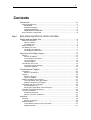
iii
Contents
Introduction............................................................................................ ix
What is RapidPLUS?................................................................................................. x
RapidPLUS........................................................................................................... x
Software Packages ............................................................................................. xi
Thinking RapidPLUS ........................................................................................... xi
RapidPLUS Documentation ............................................................................... xii
How This Book is Organized ................................................................................... xii
Day 1
BUILDING RAPIDPLUS APPLICATIONS
Modes and the Mode Tree .....................................................................3
Modes and Hierarchy ................................................................................................4
What is a Mode? ..................................................................................................4
The Mode Tree.....................................................................................................4
Mode Tree Rules .......................................................................................................6
The Mode Tree Tool ..................................................................................................7
The Mode Tree Window .......................................................................................7
Developing the Mode Tree ...................................................................................7
Objects and the Object Layout .............................................................13
Objects ....................................................................................................................14
What is an Object? .............................................................................................14
The Interface of an Object..................................................................................14
Types of Objects ................................................................................................15
The Root Object .................................................................................................15
The Object Layout Tool ...........................................................................................16
The Object Layout Window ................................................................................16
Laying Out Objects.............................................................................................16
Transitions and Triggers .......................................................................21
Transitions ...............................................................................................................22
What is a Transition?..........................................................................................22
Triggers ...................................................................................................................23
What is a Trigger? ..............................................................................................23
Types of Triggers ...............................................................................................24
Adding Transitions and Triggers .............................................................................27
The Logic Editor and Logic Palette ....................................................................27
Adding Transitions and Triggers ........................................................................28
Verification with the Prototyper................................................................................30
The Prototyper Tool............................................................................................30
Running the Application in the Prototyper..........................................................31
Transitions and Mode Hierarchy .............................................................................32
Junction Transitions.................................................................................................32
Preliminary Exercise...........................................................................................32
What is a Junction Transition? ...........................................................................33
Activities ...............................................................................................35
Activities ..................................................................................................................36
What is an Activity? ............................................................................................36
Adding Activities ......................................................................................................37
The Activities Column in the Logic Editor...........................................................37
Adding Activities .................................................................................................37
iv
RapidPLUS
Primitive and Dynamic Objects.............................................................41
Primitive Objects......................................................................................................42
What is a Primitive Object? ................................................................................42
Dynamic Objects .....................................................................................................42
What is a Dynamic Object? ................................................................................42
Dynamic Properties ............................................................................................43
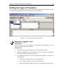
History and Special Transitions ............................................................45
Default and History Transitions ...............................................................................46
Types of Transitions ...........................................................................................46
Setting the Type of Transition ............................................................................47
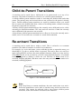
Child-to-Parent Transitions......................................................................................48
Re-entrant Transitions .............................................................................................48
Day 1 Summary....................................................................................49
Day 1 Recap............................................................................................................50
Review Questions....................................................................................................51
Summary Exercises.................................................................................................51
Day 2
BASIC DESIGN AND ADDITIONAL CONCEPTS
State Modeling......................................................................................57
State Modeling.........................................................................................................58
What is State Modeling? ....................................................................................58
Comparing the Mode Tree to State Charts ........................................................58
Exercise ...................................................................................................................59
Timer Objects .......................................................................................61
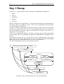
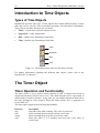
Introduction to Time Objects ...................................................................................62
Types of Time Objects .......................................................................................62
The Timer Object.....................................................................................................62
Timer Operation and Functionality .....................................................................62
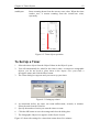
To Set Up a Timer ..............................................................................................63
Timer Methodology..................................................................................................64
Timer Reuse.......................................................................................................64
Sharing Timers Among Concurrent Modes........................................................64
Internal and Transition Actions .............................................................67
Transition Actions ....................................................................................................68
What is a Transition Action?...............................................................................68
When To Use Transition Actions........................................................................68
Internal Actions........................................................................................................70
What is an Internal Action? ................................................................................70
Using Internal Actions ........................................................................................71
Modes Revisited: Concurrency.............................................................73
Review of Modes .....................................................................................................74
Types of Modes ..................................................................................................74
The Mode Tree...................................................................................................74
Benefits of Concurrency ..........................................................................................74
Life Without Concurrency ...................................................................................74
Life With Concurrency ........................................................................................75
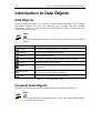
Data Objects.........................................................................................77
Introduction to Data Objects ....................................................................................78
Data Objects.......................................................................................................78
Constant Data Objects .......................................................................................78
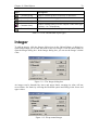
Integer......................................................................................................................79
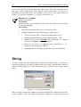
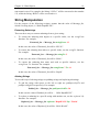
String .......................................................................................................................80
String Manipulation.............................................................................................81
Array ........................................................................................................................83
Contents
v
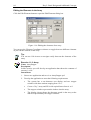
Using Arrays .......................................................................................................83
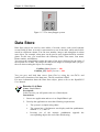
Data Store ...............................................................................................................85
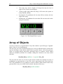
Array of Objects.......................................................................................................86
Local Variables, If Branches, and Loops ..............................................89
Local Variables ........................................................................................................90
If Branches ..............................................................................................................90
Defining an If Branch..........................................................................................91
Defining an If...Else Branch................................................................................91
For Loops ................................................................................................................91
Defining a For Loop............................................................................................92
While Loops .............................................................................................................93
Defining While Loops .........................................................................................93
Day 2 Summary....................................................................................95
Day 2 Recap............................................................................................................96
Review Questions....................................................................................................96
Day 3
INTRODUCTION TO USER-DEFINED OBJECTS
User Functions .....................................................................................99
User Functions ......................................................................................................100
What is a User Function? .................................................................................100
Creating and Editing Functions .............................................................................100
The Function Editor Window ............................................................................100
Creating a New Activity Function .....................................................................101
Creating a New Condition Function .................................................................102
Editing an Existing Function .............................................................................103
Functions That Receive Arguments .................................................................103
Working with User Functions.................................................................................104
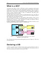
An Introduction to the GDO ................................................................107
The Graphic Display Object ..................................................................................108
What is a Graphic Display Object? ..................................................................108
Using the GDO ......................................................................................................108
Setting Up a GDO ............................................................................................108
Drawing a Pixel ................................................................................................110
Drawing Text on the GDO ................................................................................111
The Makings of a User-Defined Object...............................................115
User-Defined Objects ............................................................................................116
What is a User-Defined Object?.......................................................................116
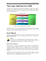
The Logic Interface of a UDO................................................................................118
Event Objects ...................................................................................................118
Exported Functions ..........................................................................................119
Events...............................................................................................................122
Properties .........................................................................................................124
Messages .........................................................................................................126
Day 3 Summary..................................................................................131
Day 3 Recap..........................................................................................................132
Exercise .................................................................................................................132
Day 4
USER-DEFINED OBJECTS METHODOLOGY
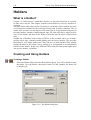
Holders and Dynamic Memory Allocation...........................................137
Holders ..................................................................................................................138
What is a Holder?.............................................................................................138
Creating and Using Holders .............................................................................138
Safety Mechanism .................................................................................................140
Dynamic Memory Allocation ..................................................................................142
vi
RapidPLUS
Dynamically Creating and Freeing Objects......................................................143
UDI: Interface-Only UDO ....................................................................145
What is a UDI? ......................................................................................................146
Declaring a UDI .....................................................................................................146
Marking a UDO as a UDI..................................................................................147
UDD: Data Container UDO.................................................................149
What is a UDD?.....................................................................................................150
Declaring a UDD....................................................................................................150
Marking a UDO as a UDD ................................................................................150
Day 4 Summary..................................................................................153
Day 4 Recap..........................................................................................................154
Summary Exercise ................................................................................................154
Day 5
CODE GENERATION BASICS
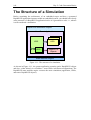
The Target Perspective ......................................................................159
The Structure of a Simulation................................................................................160
Embedded Target Architecture .............................................................................161
Interfacing the Application .....................................................................................162
The Target Perspective .........................................................................................163
The Code Generation Process ...........................................................165
Generating a Simple Application ...........................................................................166
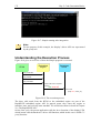
Overview of the Process ..................................................................................166
Getting Started .................................................................................................167
Understanding the Execution Process .............................................................172
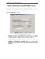
The Code Generation Preferences .......................................................................173
General Preferences ........................................................................................173
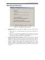
Debug Preferences ..........................................................................................174
Optimization Preferences .................................................................................175
Miscellany Preferences ....................................................................................176
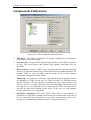
Components Preferences.................................................................................177
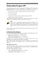
Embedded Engine API .......................................................................179
Embedded Engine API ..........................................................................................180
Initializing the Engine .......................................................................................180
Starting the Engine...........................................................................................181
Cycling the State Machine................................................................................181
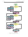
Cycle Execution Sequence ...................................................................................181
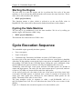
Timers API.............................................................................................................183
Continuous Timer Update ................................................................................183
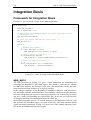
Integration Basis....................................................................................................184
Framework for Integration Basis ......................................................................184
app_api.c ..........................................................................................................184
The Parts of a RapidPLUS Embedded Project ................................................185
Integration of the Logic Interface ........................................................187
Integration Overview..............................................................................................188
Integrating an Event ..............................................................................................188
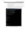
Adding the Integration Code ............................................................................189
Integrating a Property Input ...................................................................................191
Adding the Integration Code ............................................................................192
Integrating a Message Input..................................................................................194
Adding the Integration Code ............................................................................194
Updating Timers ....................................................................................................197
Day 5 Summary..................................................................................199
Day 5 Recap..........................................................................................................200
Contents
vii
Summary Exercise ................................................................................................200
Appendixes.............................................................................................203
Appendix A: The RapidPLUS User Interface .........................................205
Desktop Arrangement............................................................................................206
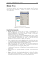
Mode Tree .............................................................................................................207
Useful Commands............................................................................................207
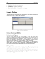
Logic Editor............................................................................................................208
Using the Logic Editor ......................................................................................208
Logic Palette..........................................................................................................210
Using the Logic Palette ....................................................................................210
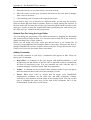
State Chart ............................................................................................................211
Prototyper ..............................................................................................................212
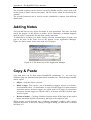
Adding Notes .........................................................................................................213
Copy & Paste.........................................................................................................213
Appendix B: Answers to Course Questions ...........................................215
Day 1 .....................................................................................................................216
Day 2 .....................................................................................................................218
Training Course
Introduction
•
What is RapidPLUS?
•
How This Book is Organized
x
RapidPLUS
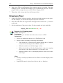
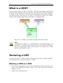
What is RapidPLUS?
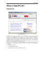
RapidPLUS
Figure Introduction-1
RapidPLUS, the product of e-SIM Ltd., is a comprehensive software package for the
generation of simulations and prototypes of electronic systems. Simulations
developed with RapidPLUS, can be linked with an external programs to obtain the
ultimate computer based training (CBT) solution. With ANSI-C code generation,
RapidPLUS enables transformation of the virtual prototype into an executable
application that can run on real embedded systems.
In general terms, RapidPLUS is an integrated development environment (IDE) for the
development of Man-Machine Interfaces (MMI). The primary uses RapidPLUS
include are:
•
Building simulations
•
Generating documentation
•
Generating ANSI-C code for embedded systems
Introduction
xi
Software Packages
RapidPLUS DOC
This is the basic RapidPLUS package that enables automatic generation of documents
and tests, directly from a simulation prototype. The generated documents can be in
two different formats: HTML and RTF.
The intended market for this package consists of:
•
Product designers
•
Human interface groups
•
Technical writers
RapidPLUS CODE
In addition to the RapidPLUS DOC capabilities, this package has the ability to
generate ANSI-C code for the target embedded system, directly from the simulation
prototype.
The intended market for this package consists mainly of embedded product
developers.
RapidPLUS Web Studio
In addition to the RapidPLUS DOC capabilities, this package is used to generate a
web-based simulation of the product. The package enables automatic generation of
JAVA™ applets and includes a tool for creating use-case scenarios of the simulation
that can run in Internet browsers.
The intended market of this package consists of:
•
Marketing and sales personnel
•
Web designers
RapidPLUS Xpress
This package is used for the creation of screen transition diagrams used in
requirements and design specifications documents.
The intended market for this package consists mainly of user-interface designers.
Thinking RapidPLUS
RapidPLUS is a high-level development tool. It draws its power from being based on
a strong state-machine. The RapidPLUS language semantics may seem familiar to
experienced software developers, but it is the concept of state-machine oriented
development that needs getting used to.
The RapidPLUS state-machine is defined by modes, and by transitions between these
modes. The most important rule of RapidPLUS application development, is building a
good set of modes, and defining the correct transitions between them.
xii
RapidPLUS
RapidPLUS Documentation
The following manuals can be found in the Given_Resources\Manuals folder:
•
Rapid Start
•
Rapid User Manual
•
User Manual Supplement
•
Generating Code for Embedded Systems
•
Methodology Guide: Building Applications for Embedded Systems
•
Generating Documents
•
Generating Web Simulations
•
The Scenario Authoring Tool
How This Book is Organized
This book is divided into five sections, each correspond to one day of the course.
Days 1 and 2 represent the process of building applications in RapidPLUS and
provide some basic design methodologies.
Days 3 and 4 mainly discuss the concept of user-defined objects and their
methodologies.
Day 5 concludes the course by giving an introduction on the code generation
capabilities of RapidPLUS.
The book also includes an appendix, which provides a brief walkthrough of the
different tools present in RapidPLUS, and their important functions. The appendix
also includes answers to different questions presented in throughout the book.
Day 1
Building
RapidPLUS
Applications
1. Modes and the Mode Tree
2. Objects and the Object Layout
3. Transitions and Triggers
4. Activities
5. Primitive and Dynamic Objects
6. History and Special Transitions
Chapter 1
Modes
and the
Mode Tree
•
Modes and Hierarchy
•
Mode Tree Rules
•
The Mode Tree Tool
4
Day 1: Building RapidPLUS Applications
Modes and Hierarchy
What is a Mode?
A RapidPLUS application is a description of a complete system whose overall
behavior is broken down into individual modes. The modes represent different
exhibited behaviors of the system. Specifically, modes separate different
functionalities of the system. For example, a television can be either off or on. These
are two distinct modes that represent different functionalities of the television.
Question 1-1:
Give an example of two different modes of a mobile phone.
A television actually has many other modes besides On and Off. For example, when
the television is on, it can be in Standby mode or Operate mode; each mode exhibits a
different concrete behavior. These are distinct sub-behaviors that are exhibited when
the television is on. Such sub-behaviors are referred to as child modes in RapidPLUS.
Child modes that are under the same parent are referred to as sibling modes. For the
television, the mode representing the standby behavior and the mode representing the
operation behavior are sibling modes under their common parent mode, On.
The Mode Tree
The parent-child hierarchy of RapidPLUS modes “branches” out, forming a tree-like
structure of modes. This structure is referred to as the Mode Tree. A general behavior
description (parent mode) can be divided into more concrete behavior descriptions
(child modes).
The Root Mode
The RapidPLUS mode tree grows out of a single mode that is referred to as the root
mode. The root mode holds all other modes and represents the most primal and
general behavior of any system: its existence. The root mode is created automatically
upon the creation of the application and by default its name is the same as the
application name.
A Visual Representation
The Mode Tree visually conveys the hierarchy among the different modes of a
system. Figure 1-1 shows a simple example of a television, in a RapidPLUS Mode
Tree.
Chapter 1: Modes and the Mode Tree
5
Television
Off
On
Standby
Operate
Figure 1-1: The mode tree of a television
A good mode tree is descriptive, in order to convey the logic of the system. A welldefined tree contains well-named modes, and a hierarchical and behavioral structure.
Another way to look at a system’s modes is through a state chart. Figure 1-2
illustrates the modes of the television in a state chart diagram:
Television
Off
On
Standby
Operate
Figure 1-2: State chart diagram of the Television
Active Modes
The modes that represent the current behavior of the system are called active modes.
There can be several active modes at any given time. For example, if the television is
on and you are watching a program, both On and Operate modes are active.
Note:
The root mode is always active.
A Default Child Mode
Figure 1-1 shows two modes with arrows pointing at them: Off and Standby. These
are default modes, representing the default behavior exhibited by the television when
their parent modes are active.
The root mode, which represents the television’s existence, is always active (i.e., the
television always exists). By default, the television is off, and as shown in Figure 1-1,
Off is the default mode under the root mode.
When you turn on the television, it is in Standby mode – the default mode under On –
until you instruct the television to operate.
6
Day 1: Building RapidPLUS Applications
Mode Types
RapidPLUS supports two types of modes: exclusive and concurrent. When you create
a new mode generation, the default type selected for the modes is exclusive. However,
you can change the selected type to concurrent.
If sibling modes are exclusive, only one of them can be active at any given time. This
type of modes separates distinct behaviors that cannot be exhibited at the same time.
For example, a human being cannot both sit and stand at the same time.
If sibling modes are concurrent, all of them will be active when their parent mode is
active (and otherwise inactive). This type of modes is used to represent behaviors that
are independent from one another. For example, a human being may stand and inhale
at the same time. Neither of these behaviors is dependent on the other.
By definition, all sibling modes under a common parent mode must be of the same
type.
The State of the System
In RapidPLUS, a mode represents a distinct behavior of the system, but as mentioned
before, a system can exhibit several behaviors at the same time. The state of the
system is thus a combination of all the active modes in the system and the status of
other system elements (the system's data), at a given time.
Important:
In RapidPLUS, mode and state are not the same!
Mode Tree Rules
A RapidPLUS application must contain at least one mode: the root mode. This makes
sense, because the root mode represents the system’s existence. The root mode has no
siblings and is considered exclusive.
When a specific mode is activated, the following is implied:
•
Its parent mode is active.
•
If it has child modes, at least one of them is active.
A mode contains RapidPLUS logic that is performed when the mode is active.
Chapter 1: Modes and the Mode Tree
7
The Mode Tree Tool
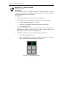
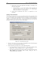
The Mode Tree Window
Figure 1-3: The Mode Tree window
The Mode Tree window is where you can add, remove and edit modes, and arrange
the modes’ hierarchy in your application. You can bring the window into focus from
the Application Manager window (see Appendix part A), in one of the following
ways:
•
Select Mode Tree from the View menu
•
Press the keyboard shortcut, Ctrl+T
•
Click the Mode Tree button in the toolbar
Reading the Mode Tree
The Mode Tree provides the following visual cues:
•
Exclusive modes—are in black letters.
•
Concurrent modes—are in blue letters.
•
Default modes—have an arrow pointing towards them.
•
Mode in focus—is highlighted with a cyan background. This is the mode
selected for editing.
Developing the Mode Tree
The Tree menu provides the commands necessary to add, remove, edit, and arrange
modes as you develop the application's mode tree. These and other commands are
accessible in a popup menu by right clicking in the Mode Tree area.
To select a mode in the Mode Tree: click the mode name or use the up/down arrow
keys to highlight it.
8
Day 1: Building RapidPLUS Applications
Adding a New Child Mode
1.
Select a parent mode.
2.
From the Tree menu, select New Mode. Alternatively you can use the keyboard
shortcut Ctrl+W, or the New Mode button. The New Mode dialog box opens.
Figure 1-4: The New Mode dialog box
3.
Type the name of the new mode.
4.
If this is the first mode under the selected parent, choose its type: Exclusive or
Concurrent.
5.
Click the Accept button to add the mode.
6.
The New Mode dialog box remains open so that you can continue adding new
modes. Click a different mode in the Mode Tree to add children under that mode.
7.
When done, click the Close button.
Chapter 1: Modes and the Mode Tree
9
Mode Names and Conventions
The following rules apply to mode names:
•
A name can contain only letters (upper and lower case), numbers, and the
underscore sign. Illegal characters are replaced with an underscore sign by
RapidPLUS.
•
A name must start with a letter (upper or lower case) or the underscore
sign.
•
Names are case sensitive, thus SITTING is not the same as Sitting or
sitting.
•
Modes can have the same name, as long as they have different parent
modes.
•
The following words are reserved, and cannot be used as names: action,
and, begin, clear, end, entry, exit, has, internal, is, mode, not, or,
resetValue, self, subroutine, x, y.
The following mode naming conventions are recommended:
•
Exclusive modes should be capitalized. If the mode name needs more than
one word, each word should be capitalized, without underscores to separate
the words.
•
Concurrent modes should be written completely in uppercase. If the mode
name needs more than one word, an underscore sign should be used to
separate the words.
Editing a Mode’s Name
1.
Select the mode to be edited.
2.
From the Tree menu, select Edit Mode. Alternatively you can use the keyboard
shortcut Ctrl+E. The Edit Mode dialog box opens.
3.
Edit the mode's name.
4.
Click the Accept button to confirm the change.
5.
The Edit Mode dialog box remains open, so you can continue editing other modes
6.
When done, click the Close button.
Tip:
You can switch between adding modes and editing existing ones from
within the respective dialog boxes. In the New Mode dialog box, click the
Edit button, and in the Edit Mode dialog box, click the New button.
10
Day 1: Building RapidPLUS Applications
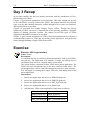
Exercise 1-1: Developing a mode tree
Name: Television1
Description:
In this exercise you will develop a simple Mode Tree for a television.
Instructions:
1.
Start a new application.
2.
Save the application as Television1.rpd.
3.
Build a mode tree for the application according to the following
requirements (default modes are underlined):
4.
The television can be either Off or On.
5.
When On it can either be in Standby or Operate modes.
Inserting a New Generation of Modes
You can add a new generation of modes in between two current generations, by
inserting a mode as a child of a selected mode, while automatically making that
selected mode's children, the new mode's children.
1.
Select the mode you wish to be the parent of the newly inserted generation.
2.
From the Tree menu, select Insert. Alternatively you can use the keyboard
shortcut keys Ctrl+I. The Insert Mode dialog box opens.
3.
Type the name of the new mode.
4.
Select the type of the modes in the newly inserted generation.
5.
Click the Accept button to insert the mode.
6.
When done, click the Close button.
Removing a Mode
You can permanently remove a mode from the mode tree. The children of the
removed mode, becomes children of that mode's parent.
1.
Select the mode to be removed.
2.
From the Tree menu, select Remove. Alternatively you can press the keyboard
Delete key.
Note:
A mode can only be removed if its child modes are of the same type as it is,
or if it has no siblings. This is due to the child modes becoming children of
the removed mode's parent, i.e. they become siblings of the removed
mode's siblings.
Additional Commands
You can find explanations of additional Mode Tree tool commands in the RapidPLUS
User Manual or the RapidPLUS Online Help.
Chapter 1: Modes and the Mode Tree
11
Exercise 1-2: Developing a mode tree
Name: Television2
Description:
In this exercise you will insert a new generation of modes to the Mode Tree
you started on Exercise 1-1.
Instructions:
1.
Open Television1.rpd.
2.
Save the application as Television2.rpd.
3.
Adapt the mode tree of the application to the following new
requirements:
•
The television, being an electrical home appliance, has a power
cord. This power cord can be either Plugged to a power outlet or
Unplugged.
•
When the television is operating, it can either display a channel or
the setup program.
Chapter 2
Objects
and the
Object Layout
•
Objects
•
The Object Layout Tool
14
Day 1: Building RapidPLUS Applications
Objects
What is an Object?
As RapidPLUS applications simulate real-life systems, they need to visually represent
a system's interface, and hold its internal data. RapidPLUS objects are elements of a
RapidPLUS application that imitate their real-life counterparts and provide these
abilities to the application.
RapidPLUS objects have pre-defined sets of properties and functions that describe
how the object can behave in runtime. For example, a real lamp can either be off or
on. RapidPLUS has a lamp object that exhibits the same functionality.
Unlike other visual development tools (e.g., Visual Basic™), RapidPLUS objects are
used solely as elements within the code. Coding is not done within the context of an
object, but within the context of a mode, or in some cases, within the context of a
transition between modes. Transitions are discussed in Chapter 3: “Transitions and
Triggers”.
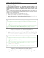
Coding within the context of an object in Visual Basic™
A subroutine in Visual Basic™ for handling pressing of a button, is a good
example of “coding within the context of an object”:
Private Sub Button1_Click()
‘ Handling code goes here...
End Sub
The Interface of an Object
Each object in RapidPLUS has its own characteristics – properties, functions and
events – that allow you to control its behavior, and receive signals from it.
Properties
Each property of an object controls a specific aspect of the object's behavior. For
example, a real 2-position horizontal toggle switch can be either in left or right
positions. The RapidPLUS counterpart has two equivalent properties, left and right.
RapidPLUS objects also have a “self” property, designated by an ellipsis (...), which
refers to the object as a whole.
Functions
Every property has functions that can either read or write that property's data, or
adjust the property itself. Read and write functions manipulate the property's data,
while adjustment functions manipulate the object itself. For example, both the left and
right properties of the 2-position horizontal toggle switch have a connect function. If
Chapter 2: Objects and the Object Layout
15
the left property receives the call, the lever of the switch moves to the left. If the right
property receives the call, the lever moves to the right.
Events
Objects generate events to notify the application when a specific status change occurs
in them. For example, when a pushbutton object is clicked, it gives the application an
in event.
Types of Objects
There are two types of objects: graphic objects and nongraphic objects.
Graphic Objects
Graphic objects give the application its appearance and interface with the user.
Graphic objects are used in the RapidPLUS logic to receive input from the user and to
indicate the system's status back to the user. These objects are divided into two
groups:
•
Active objects—play an "active" role in the simulation, and can be manipulated
in runtime. For example: lamps, switches, dials, displays, etc.
•
Primitive objects—are used to enhance the appearance of the simulation, and
cannot be manipulated in runtime. For example: lines, frames, labels, etc.
Nongraphic Objects
Nongraphic objects, as the name implies, have no graphic representation in runtime.
They are used in the RapidPLUS logic to hold the system's data, enable time-based
functionality, and support messaging between different parts of the application.
For example, a Number object can contain a real floating-point numeric value
representing a channel frequency, while a Timer object can count down the seconds
before the backlight on a mobile phone display turns off.
The Root Object
Like with modes, RapidPLUS objects are also arranged in a hierarchy. The topmost
object in the hierarchy, parenting all other objects in the application, is the root object.
The name of the root object is self, and it is sometimes referred to as the TopPanel.
The dimensions of the root object denote the dimensions of the application, that is, the
size of the application window at runtime.
16
Day 1: Building RapidPLUS Applications
The Object Layout Tool
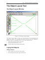
The Object Layout Window
Mouse coordinates box
Object types
Object palette
Work area
Object classes
Line width
Figure 2-1: The Object Layout window
The Object Layout window is where you can add objects to your application and
arrange their layout. You can bring the window into focus from the Application
Manager window (see Appendix part A), in one of the following ways:
•
Select Object Layout from the View menu
•
Press the keyboard shortcut, Ctrl+A
•
Click the Object Layout button in the toolbar
Laying Out Objects
Adding an Object
1.
Select an object class from the Object palette.
2.
Select the appropriate object type from that class.
Chapter 2: Objects and the Object Layout
3.
17
Place the object in the work area by clicking the desired location.
Tip:
You can determine the size of an object by dragging the cursor while
placing the object in the work area.
Arranging Objects
The Layout menu provides the commands for aligning, centering, distributing, and
ordering of objects. These commands are useful to make a clean and appealing layout.
The Group menu provides the commands for handling groups of objects. Note that
objects in a group can be edited separately by selecting the group and then Edit from
the Group menu. Once done, select End Edit Group from the Group menu and
continue editing normally.
You can move objects around by dragging them with the cursor or by holding the
Shift key and using the arrow keys. You can also resize an object by dragging its
sizing handles to the required size.
Exercise 2-1: Laying out objects
Name: Layout
Description:
In this exercise you will arrange objects in the Object Layout.
Instructions:
1.
Start a new application and save it as Layout.rpd.
2.
In the Object Layout, add nine square pushbuttons.
3.
Arrange the buttons in a 3×3 formation, equally distributed both
horizontally and vertically.
4.
Add a square corners filled frame behind the pushbuttons to complete
the layout.
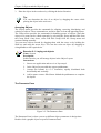
The Parameter Pane
Figure 2-2: The Parameter Pane
The Parameter Pane is where you set up different object parameters in design time.
Double-click a graphic object to open its Parameter Pane.
18
Day 1: Building RapidPLUS Applications
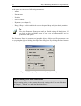
In the pane you can set the following parameters:
•
Name
•
Parent name
•
Position
•
Size or Radius
•
Dynamic (see chapter 5)
•
Drag ’n Drop—which enables the user to drag and drop an object during runtime.
Tip:
Leave the Parameter Pane open until you finish editing all the objects. If
you click an object while the pane is open, you will automatically see its
parameters in the pane.
The Parameter Pane is common to all graphic objects. Object specific parameters can
be set using that object’s dialog box. Open the dialog box by clicking the More button
in the Parameter Pane.
Figure 2-3: The specific parameters of a pushbutton object
Object naming rules and conventions
Object naming rules are the same as the mode naming rules. You can find these
in chapter 1, "Mode Tree and State Machine Rules".
Chapter 2: Objects and the Object Layout
19
The following object naming conventions are recommended:
•
Object names should be capitalized.
•
If the object name needs more than one word, each word should be
capitalized, without underscores to separate the words.
•
The end of the name is concatenated with an underscore, followed by an
abbreviation of the object type.
The following table lists some common objects with their abbreviation:
Object and abbreviation
Pushbutton
Pb
Switch
Sw
Lamp
Lmp
Timer
Tmr
Event
Ev
Bitmap
Bmp
Image
Img
Object and abbreviation
Display
Dsp
Number
Num
Integer
Int
String
Str
Array of type T
TAry
Data store
Ds
Constant of type T
CT
Examples: Power_Pb, Status_Lmp
Additional Editing Tools
There are several other ways you can edit objects to suit your needs. You can change
the line width and the colors used to draw the object, you can hide objects in design
time and you can even use the Object Editor to change the complete look and feel of
the object.
The Object Editor lets you edit the appearance of the object, adjust the object's active
areas (its hotspots) and change the appearance of the cursor used when it is over the
object.
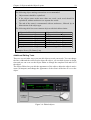
Figure 2-4: Edited objects
20
Day 1: Building RapidPLUS Applications
Figure 2-4 illustrates the usage of edited objects. The power cord for example is
actually a simple horizontal slider switch. The control buttons are simple pushbuttons
textured with the appropriate image.
Note:
Editing objects in the Object Editor changes their graphic from vector
format to bitmap format.
To learn more about editing objects using the object editor, refer to the RapidPLUS
User Manual or the RapidPLUS Online Help.
Exercise 2-2: Laying out objects
Name: Television3
Description:
In this exercise you will start to give the television’s front panel its
appearance.
Instructions:
1.
Open Television2.rpd and save it as Television3.rpd.
2.
Add the following objects to the Object Layout:
•
Small round lamp.
•
A square pushbutton.
•
Rocker switch.
•
Horizontal slider switch.
3.
Arrange the objects in a straight line from left to right, with equal
spaces between them.
4.
Name the objects according to their usage:
5.
•
Lamp: Indicates the status of the television.
•
Slider switch: Imitates power connection.
•
Rocker switch: Used for turning the power on and off.
•
Pushbutton: Used for toggling between Standby and Operate.
Finish the layout by adding a dark grey frame behind the objects.
Chapter 3
Transitions
and
Triggers
•
Transitions
•
Triggers
•
Adding Transitions and Triggers
•
Verification with the Prototyper
•
Transitions and Mode Hierarchy
•
Junction Transitions
22
Day 1: Building RapidPLUS Applications
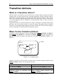
Transitions
What is a Transition?
As mentioned in Chapter 1, "Modes and the Mode Tree", the system's overall
behavior is broken down into modes. Each mode represents a specific behavior that
the system exhibits at a given time, and the system can shift from one active mode to
another. For example, when the television set is off, it can be turned on. This will
deactivate the Off mode and activate the On mode. The ability to move from one
mode (behavior) to another is called a transition.
A transition is, therefore, a route from a source mode to a destination mode. The sum
of all transitions between the modes of the system represents the potential changes in
the state of the system.
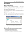
Graphical Representation of Transitions
In state charts, transitions are represented as arrows between the modes, originating
from a source mode to a destination mode. Figure 3-1 shows the State Chart tool
displaying modes with transitions between them.
Figure 3-1: State Chart tool displaying modes with transitions
Constraints on Transitions
There are several rules regarding transitions, summarized in the following list:
•
A transition can originate from any mode in the tree.
•
A concurrent mode cannot be the target for a transition.
•
Transitions are not allowed between concurrent branches in the mode tree.
Chapter 3: Transitions and Triggers
23
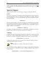
Question 3-1:
In the mode tree to the right, exclusive modes begin
with an E, and concurrent modes begin with a C. Mark
the transitions that are legal.
Legal
Illegal
Transition
E1E2
C22C21
E111E121
C22E222
E221E111
E121System
Triggers
What is a Trigger?
Transitions determine where the system can shift to from any given mode, but they
don't tell us why or what causes the shift. To answer this question we attach triggers
to the transitions. Each transition can have one or many triggers. The triggers are the
reasons for executing the transition.
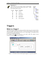
For example, when Off, the television set can shift to On. The trigger for this
transition is turning the hard on/off switch on.
Figure 3-2: The State Chart tool showing the trigger for a specific transition
24
Day 1: Building RapidPLUS Applications
Figure 3-2 shows the trigger responsible for the execution of the transition from Off
mode to On mode. The selected transition is marked in red, and its trigger is shown at
the bottom.
Types of Triggers
RapidPLUS differentiates between two types of triggers: events and conditions.
Events
An event is a notification of a change to a specific property of an object. Events are
generated immediately upon the occurrence of the change. For example, when you
press a pushbutton, an in event of that pushbutton is generated. In RapidPLUS syntax,
this event looks like:
Pushbutton in
You can combine multiple events into one trigger by concatenating each event after
an exclamation mark. Events cannot occur simultaneously, so for the transition to be
triggered only one of the concatenated events needs to occur. In RapidPLUS syntax a
trigger of multiple events looks like:
Pushbutton in ! Timer tick
According to this trigger, the transition is executed when a pushbutton is pressed in,
or when a timer sends a tick event 9more about timers in chapter 8).
Conditions
Conditions are logical tests performed repeatedly on a property. As long as the result
of the test is False, nothing happens. Once the result is True, the transition is
executed. For example, the following condition tests the position of a rocker switch:
& RockerSwitch.up is connected
As long as the switch is down, the test result is False. When the switch is up, the test
result is True and the trigger is executed.
Note:
The ampersand (&) is a delimiter for the start of a condition.
You can combine multiple conditions into one trigger by using logical relations such
as or, and, and not. In RapidPLUS syntax a multiple-conditions trigger with and
would look like:
& RockerSwitch.up is connected and IntegerObject > 50
Chapter 3: Transitions and Triggers
25
Compound Triggers
You can combine events and conditions to make one compound trigger. In this case,
the transition will be triggered when the condition (single or multiple) is True, and
the event (single or multiple) is generated. In RapidPLUS syntax, a compound trigger
made of one event and one condition looks like:
Pushbutton in & RockerSwitch.up is connected
Question 3-2:
For each of the following triggers, when will the transition be executed?
•
Event1 ! Event2
1. When both events take place.
2. When either event takes place.
3. Never, illegal trigger.
•
Event & Condition1 or Condition2
1. When the event is generated and either condition is True.
2. When the event is generated or either condition is True.
3. Never, illegal trigger.
•
Event1 or Event2 & Condition
1. When at least one of the events is generated and the condition is True.
2. When at least one of the events is generated or the condition is True.
3. Never, illegal trigger.
Events vs. Conditions
It is important to distinguish between the two types of triggers. Events occur when
there is a change in an object's status, and immediately trigger the transition;
conditions are checked repeatedly and only trigger the transition when the result is
True. Table 3-1 summarizes the differences between events and conditions.
Definition
Method
Occurrence
Triggers
Evaluated
Event
Notification of change
to an object’s status
Interrupt
Once
Immediately
Condition
Check of an object’s
current status
Polling
Continuously
When True
Table 3-1: Differences between events and conditions
26
Day 1: Building RapidPLUS Applications
Persistency With Conditions
Some behaviors require the specific use of conditions. For example, the requirements
for a system say that when you turn a switch up, a lamp should turn on, and when you
turn the switch down, the lamp should turn off.
From these requirements, you can assume that event triggers may be suitable. When
you turn the switch up, an event is generated and executes a transition from Off mode
to On mode. The same can be applied in the other direction.
A problem arises with a new requirement: a real lamp turns off when there is a power
outage, if the switch is up when the power returns, the lamp turns on without
intervention, i.e. you wouldn't need to make any changes to the system.
If you use an event as the trigger for the transition from Off to On, you would have a
system that doesn't act as it should, because the power coming back on will not
generate the event of turning the switch up. The switch is already up.
You can solve this problem by using a condition instead of an event as the trigger for
this transition. Instead of waiting for an event to be generated, you can check the
status of the switch repeatedly. This way, when the power comes back on, and the up
position of the switch is connected, checking the condition gives a True result—which
triggers the transition to On.
Chapter 3: Transitions and Triggers
27
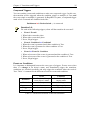
Adding Transitions and Triggers
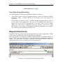
The Logic Editor and Logic Palette
Figure 3-3: The Logic Editor and Logic Palette
The Logic Editor window is where you can write the RapidPLUS logic for your
application. You can bring the window into focus from the Application Manager
window (see Appendix part A), in one of the following ways:
•
Select Logic Editor from the View menu,
•
Press the keyboard shortcut, Ctrl+L, or
•
Click the Logic Editor button in the toolbar.
The Logic Palette window is a utility window from which you can easily access the
objects used in your application, their properties and their functions. You can use the
Logic Palette to quickly add these elements to your application logic.
28
Day 1: Building RapidPLUS Applications
Tip:
If the Logic Palette window doesn’t open automatically with the Logic
Editor window, click the Logic Palette button in the Logic Editor window
to open it.
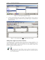
Adding Transitions and Triggers
Continuing with the example of the television, you can add a transition from Off to
On, and an appropriate trigger.
Adding a Conditional Transition
1.
In the Logic Editor, select Off from the drop-down list of modes at the top of the
window. You can also select the mode by clicking it in the Mode Tree.
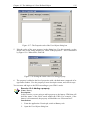
2.
Click the first row in the Destinations column. Two drop-down list boxes appear
beneath the top one. The one on the left show the word Default.
3.
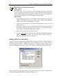
From the drop-down list box on the right, select the On mode, as shown in Figure
3-4.
Figure 3-4: Selecting a destination mode for the new transition
4.
After you select the destination for the transition, the next column in the Logic
Editor is enabled; this is the triggers column. Click on Condition at the top of the
column to enable the use of condition functions.
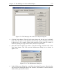
5.
In the Logic Palette, double-click the Switch class in the Object column, and
select the hard on/off switch. Select the up property and the is connected
function.
Chapter 3: Transitions and Triggers
29
Figure 3-5: Selecting the appropriate trigger
6.
Click the Append button in the Logic Palette. This appends the correct syntax of
the condition to the triggers column in the Logic Editor. Figure 3-6 illustrates the
finished transition.
Figure 3-6: The transition from Off to On along with its trigger
Adding Other Triggers to the Same Transition
As mentioned before, a transition can have more than one trigger attached to it. In
order to add another trigger to the same transition, not as a combination, but as a
completely different trigger, simply select the next row in the triggers column, click
Event or Condition, and repeat steps 5 to 6.
Tip:
You can activate the Logic Editor, ready to add new transitions from a
selected mode. First, select the mode in the Mode Tree, and then click the
New Transition button
30
Day 1: Building RapidPLUS Applications
Tip:
You can quickly add all the transitions between the modes directly in the
Mode Tree First click the New Transition button and than add the
transitions by selecting the source mode (highlighted in cyan) and Alt+click
the destination modes (momentarily highlighted in magenta).
Exercise 3-1: Adding transitions and triggers
Name: Television4
Description:
In this exercise you will appropriate transitions to the television application.
Instructions:
1.
Open Television3.rpd and save it as Television4.rpd.
2.
Add the following transitions, and their respective triggers, to the
application:
3.
•
Unplugged Plugged Unplugged.
•
Off On Off.
•
Standby Operate Standby.
Don't add transitions between the channel viewing and the setup
modes.
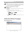
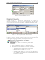
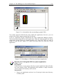
Verification With the Prototyper
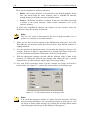
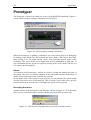
The Prototyper Tool
Figure 3-7: The Prototyper window
Chapter 3: Transitions and Triggers
31
The Prototyper window is where you can verify and test your application. You can
bring the window into focus from the Application Manager window (see Appendix
part A), in one of the following ways:
•
Select Prototyper from the View menu,
•
Press the keyboard shortcut, Ctrl+R, or
•
Click the Prototyper button in the toolbar.
Running the Application in the Prototyper
To run the application, select Start from the Controls menu. The state machine
activates the root mode and the default child mode. For the television application,
these would be the Television and Unplugged modes. The objects are shown in the
Prototyper window, and you can start testing the application.
Tracing the Logic
When testing your application, you can trace the transitions between the modes. This
is called first-level debugging.
To enable tracing, select Trace from the Options menu. When marked, this option
shows the modes that are active at any given time. Notice that the root mode and
some other modes in the Mode Tree window are highlighted in grey. These are the
active modes. If you've just started the Prototyper on the television example, the
highlighted modes should be Television (which will always be active) and
Unplugged.
Tip:
When developing, make it a habit to leave Trace marked.
Testing the Application
Test your application by operating it as your prospective users would. Click on the
active areas of the switches and buttons, and look at the Mode Tree to see the active
modes.
In the example of the television you would first plug the television to the power
outlet. Use the switch that represents the power cord to do so. Notice the change in
active modes. Unplugged is no longer highlighted and instead, Plugged and Off are
now highlighted.
Exercise 3-2: Testing the application
Name: Television4
Description:
In this exercise you will verify the transitions and triggers you added to the
television on Exercise 3-1.
Instructions:
1.
Open Television4.rpd.
32
Day 1: Building RapidPLUS Applications
2.
3.
Use the Prototyper to test the application. Possible use cases:
•
Plug the system, turn it on and toggle it between Standby and
Operate modes.
•
Turn the system on before plugging it and then plug it.
Does the system behave as expected?
Transitions and Mode Hierarchy
You can define two and more different transitions in the mode tree that use the same
trigger, even two transitions from the same mode.
When a trigger is generated, the RapidPLUS state-machine passes it down the Mode
Tree, through the active modes. The first mode containing a transition that uses the
trigger, executes its transition. If the mode has two or more transitions using that
trigger, the transition defined first in the Destinations column in the Logic Editor, is
executed. In other words, transitions from modes, higher in the hierarchy, are
committed first, thus overriding transitions from lower modes that use the same
trigger.
Junction Transitions
Preliminary Exercise
Exercise 3-3: Junction transitions
Name: BrainTeaser
Description:
In this exercise you are required to come up with a design for a system
under the constraint of using a minimal number of transitions.
Instructions:
1.
Start a new application and save it as BrainTeaser.rpd
2.
Construct a mode tree with three exclusive modes: M1, M2 and M3.
3.
Layout three pushbuttons and name them: Pb1, Pb2 and Pb3.
4.
Add a minimal number of transitions to the system so that each button
will move the system to its respective mode, e.g. Pb3 will move the
system to mode M3, from any source mode.
Question 3-3:
What is the minimal number of transitions required to implement a solution
to Exercise 3-3?
Chapter 3: Transitions and Triggers
33
Question 3-4:
What type or types of triggers are used in the implementation you suggested
to Exercise 3-3?
What is a Junction Transition?
A common element in many applications is a switch or a series of pushbuttons that
shifts the application between a series of sibling modes.
The most obvious (but not the best) solution to such a requirement is to have a
transition from anyone of these modes to all the others, as illustrated in Figure 3-8.
BrainTeaser
M1
M2
M3
Figure 3-8: Obvious solution
This solution has a major disadvantage: the number of transitions grows in a
geometrical relation to the number of sibling modes. In this example we have 6
transitions. Add another mode and the number of transitions will grow to 12. Add yet
another mode and the number of transitions will grow to 20.
There is a better solution. Instead of making the transitions originate from each child,
have them originating from the parent. This works because the parent mode is also
active so it'll receive the trigger and execute the transition. By choosing this solution,
we reduce the number of transitions to one per child mode. Adding another child will
result in adding only one transition. Figure 3-9 illustrates this solution.
BrainTeaser
M1
M2
M3
Figure 3-9: Junction type solution
34
Day 1: Building RapidPLUS Applications
Junctions Without a Default Child
Sometimes, a special case of junction can replace the use of a default child. Take for
example a system with a power switch, and a 3-stations rotary switch that selects
between 3 modes of operation. When we power up the system, it should immediately
be in the mode indicated by the 3-stations rotary switch. This requirement eliminates
the need for a default child. Instead we use a junction from the parent mode, which in
this case may be the root mode, to each and every one of the operation modes. The
junction transition we are using has condition-only triggers that check the status of the
rotary switch.
There are two things we need to remember about condition-only junction transitions:
•
When using condition-only triggers in a junction and there is no default mode,
one of the conditions must be True, when the parent mode is activated.
•
Condition-only triggers from a parent tend to "lock" the system on one child
when True. In order to move to another mode, the condition value must be
changed.
Exercise 3-4: Adding transitions and triggers
Name: Television 5
Description:
In this exercise you are required to come up with a design for a system
under the constraint of using a minimal number of transitions.
Instructions:
1.
Open Television4.rpd and save it as Television5.rpd.
2.
Replace the transitions between Off and On with a junction from their
parent mode Plugged.
3.
Verify the new junction transition you made with the Prototyper.
Chapter 4
Activities
•
Activities
•
Adding Activities
36
Day 1: Building RapidPLUS Applications
Activities
What is an Activity?
Modes represent different behaviors exhibited by the system. If the mode names are
descriptive, you can get a sense for the system behavior just by examining the mode
tree. However, this is not enough. You should actually feel the behavior, not just
know that it is supposed to be exhibited by the system. For example, when the system
is turned on, the status LED should indicate that the system is active.
Activities are lines of logic that are added to modes and operate on the objects at
runtime. The activities of a mode are executed whenever the mode is active. There are
three types of activities, distinguished by the time frame in which they occur:
•
Entry activities—occur when the mode becomes active.
•
Exit activities—occur when the mode becomes inactive.
•
Mode activities—occur repeatedly as long as the mode is active.
Note:
When the application is started in the Prototyper, all entry activities of all
the active modes are executed. When the application is stopped, all exit
activities of all the active modes are executed.
Some functions of an object can only be used as entry or exit activities and never as
mode activities. For example, it makes no sense to repeatedly restart a stopwatch as
long as the mode is active. The RapidPLUS stopwatch object’s restart function is thus
only accessible as an entry or exit activity. Other RapidPLUS objects have other
functions that cannot be used as mode activities.
Chapter 4: Activities
37
Adding Activities
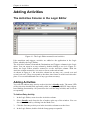
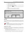
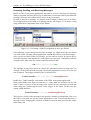
The Activities Column in the Logic Editor
Figure 4-1: The Logic Editor zoomed in on Activities
Like transitions and triggers, activities are added to the application in the Logic
Editor, aided by the Logic Palette.
The Activities column is beneath the Destinations and Triggers columns in the Logic
editor. You can zoom in on any column by double-clicking a row in it. Figure 4-1
shows the Logic Editor window zoomed in on the Activities column. With the
Activities column zoomed in, it is easier to focus on the task at hand.
As shown in Figure 4-1, the Activities column has an entry row, a mode row and
several exit rows. These correspond to the three time frames in which activities take
place. You can add additional rows of any type when necessary.
Adding Activities
You will now add an entry activity to the television’s Standby mode. The status LED
of the television should blink repeatedly while in standby. RapidPLUS lamp objects
have blinking functionality. All you need to do is tell the lamp to blink, and it will do
so repeatedly.
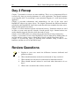
To Add an Entry Activity
1.
In the Logic Editor, zoom in on the Activities column.
2.
Select Standby mode from the list of modes at the top of the window. You can
also select the mode by clicking it in the Mode Tree.
3.
Click the first entry activity row in the Activities column to set the focus.
4.
In the Logic Palette, double-click the Lamp group to expand it.
38
Day 1: Building RapidPLUS Applications
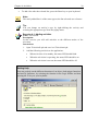
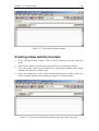
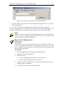
5.
Select the status LED lamp, and then select the blink function, as shown in Figure
4-2.
Figure 4-2: Selecting the appropriate activity
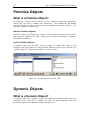
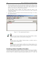
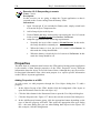
6.
Click the Append button in the Logic Palette. This will append the correct syntax
of the activity to the Activities column in the Logic Editor. Figure 4-3 illustrates
the finished activity.
Figure 4-3: The entry activity for Standby mode
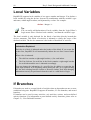
To Add Additional Activity Lines
As mentioned before, you can add additional activity lines when needed. These new
lines can come before (above) or after (below) existing filled lines. To add a new
activity line, do the following:
1.
Set focus on the filled activity line you wish the new line to come before or after.
2.
Add the new line as follows:
•
To add a line before the selected line, press the Insert key on your keyboard.
Chapter 4: Activities
•
39
To add a line after the selected line, press the Enter key on your keyboard.
Note:
The newly added line is of the same type as the line selected as a reference.
Tip:
You can change an activity’s type by right-clicking the activity and
selecting the appropriate type from the popup menu.
Exercise 4-1: Adding activities
Name: Television6
Description:
In this exercise you will add activities to the different modes of the
television.
Instructions:
1.
Open Television5.rpd and save it as Television6.rpd.
2.
Add the following activities to the application:
•
When television is in standby, the status LED should blink.
•
When the television is operating, the status LED should be on.
•
When the television is not on, the status LED should be off.
Getting Help
You can get help on the different functions of an object, both trigger functions
and activity functions, by selecting the function in the Logic Palette and then
pressing the F1 key on your keyboard.
40
Day 1: Building RapidPLUS Applications
Exercise 4-2: Enhancing the television
Name: Television7
Description:
In this exercise you add additional activities to the television.
Instructions:
1.
Open Television6.rpd and save it as Television7.rpd.
2.
Adapt the application to the following new requirements:
•
The television set has a 5-character text display, for displaying
information.
•
When in standby, the display shows “-----”.
•
When viewing a channel, the display shows the station’s number.
•
Other than that, the display should be blank.
Question 4-1:
In Exercise 4-2, what property of the text display object did you use?
Question 4-2:
Answer the following questions about the television:
•
Why does the status LED turn on?
•
If implemented correctly, the lamp turns off when we unplug the
television. Why is that?
•
Does it matter where we put the lamp off activity? What options do we
have?
Chapter 5
Primitive
and
Dynamic Objects
•
Primitive Objects
•
Dynamic Objects
42
Day 1: Building RapidPLUS Applications
Primitive Objects
What is a Primitive Object?
In Chapter 2, “Objects and the Object Layout,” primitive objects were defined as
objects that are used to enhance the appearance of the simulation. By default,
primitive objects are inactive and cannot be manipulated at runtime. However, you
can make a primitive object active.
Inactive Primitive Objects
Primitive objects, by default, have no name. They are not listed in the Logic Palette,
and cannot be added to the logic. Thus they are inactive, and indeed, cannot be
manipulated at runtime.
Active Primitive Objects
A primitive object can be made active by giving it a name. The object is then
available in the logic. However, only the basic functions, such as show and hide, are
available. Figure 5-1 shows the functions of an active circle.
Figure 5-1: The functions of an active circle
Dynamic Objects
What is a Dynamic Object?
A dynamic object is a graphic object with additional properties that control its
orientation, size, and color at runtime. To make an object dynamic, select the
Dynamic property in the Parameter Pane at design time.
Chapter 5: Primitive and Dynamic Objects
43
Figure 5-2: Setting the Dynamic property
Dynamic Properties
As shown in Figure 5-3, a dynamic filled circle object has five properties for
controlling its center position, fill color, line color, Z-order position, and radius. Each
of these properties has its respective functionality for adjusting that property’s values.
Figure 5-3: Added properties for the filled circle object
In addition to these new functions, the object becomes sensitive to click events. That
is, when the user clicks it with the mouse, the object generates an event.
Exercise 5-1: Primitive objects and Dynamic
Name: MovingCircle1
Description:
In this exercise you will use an active dynamic primitive object.
Instructions:
1.
Start a new application and save it as MovingCircle1.rpd.
2.
Develop an application that meets the following requirements:
•
The system contains a filled circle and a rocker switch.
•
When the switch is down, the circle is at rest.
•
When the switch is up, the circle moves from left to right and vice
versa along the X-axis, with its center position ranging from 50 at
the left to 250 at the right.
44
Day 1: Building RapidPLUS Applications
3.
Use mode activities to move the circle.
Question 5-1:
In Exercise 5-1, if you turn the switch off and then back on, in what
direction will the circle move?
Chapter 6
History and
Special
Transitions
•
Default and History Transitions
•
Child-to-Parent Transitions
•
Re-entrant Transitions
46
Day 1: Building RapidPLUS Applications
Default and History Transitions
Types of Transitions
There are three types of transitions in RapidPLUS, each marked with a different letter:
•
Default transition (D)
•
History transition (H)
•
Deep history transition (P)
The type of transition determines which child modes will be activated upon activating
a parent mode that was already active sometime in the past. The type of transition is
defined during design time.
Default Transition
When a default transition is made to a parent mode, its default child is activated. This
is the type of transition you have worked with so far.
History Transition
The first time a history transition is made to a parent mode, the default child is
activated. The next time the transition is made, the most recently active child mode is
activated. This is not necessarily the default child.
Deep History Transition
The first time a deep history transition is made to a parent mode with several
generations of descendents, the default child is activated at each generational level.
The next time the transition is made, the most recently active descendant at each
generational level is activated. Again, these may not be the default modes at their
respective levels.
Question 6-1:
In the Mode Tree to the right, a transition is made
from Parent2 to Parent1. When the transition is
made back from Parent1 to Parent2, which modes
will be activated for each type of transition?
•
Default:
•
History:
•
Deep history:
Chapter 6: History and Special Transitions
47
Setting the Type of Transition
You set the type of transition in the Logic Editor, while defining the transition. Figure
6-1 shows the transition type drop-down list in the Logic Editor.
Figure 6-1: Transition type drop-down list
Exercise 6-1: Transition types
Name: MovingCircle2
Description:
In this exercise you will enhance the MovingCircle application so it’ll
behave in a more persistent manner.
Instructions:
1.
Open MovingCircle1.rpd and save it as MovingCircle2.rpd.
2.
Adapt the application so that when the circle is stopped, resuming its
movement will not change its direction.
3.
For additional practice in activities, adapt the application to these new
requirements:
•
Add two text display objects to the application.
•
In one display, indicate the movement direction.
•
In the other display, indicate the circle’s position along the X-axis.
48
Day 1: Building RapidPLUS Applications
Child-to-Parent Transitions
A transition can be made from a child mode to its parent mode or to any of its
ancestors. This kind of transition is referred to as a child-to-parent transition.
A default child-to-parent transition results in activating the default child under that
parent. The parent's entry and exit activities are not executed, as the parent is already
active. Default child-to-parent transitions are useful in situations where you would
like to return to the default child from a subset of its sibling modes, without executing
the parent's entry and exit activities.
A history child-to-parent transition keeps the currently active child mode active, while
activating its default descendants. The entry and exit activities of both the currently
active child and of the parent are not executed.
A deep history child-to-parent transition has no effect as it leaves the currently active
modes, active. No activities are executed as a result of this transition.
Re-entrant Transitions
A transition can be made from a mode to itself. This is referred to as re-entrant
transition. This kind of transition is useful for reset behavior.
For example, in a voice mail menu, you are told that in order to repeat the menu, you
should dial 0. You do so, and the menu is repeated. This can be done over and over
again. In RapidPLUS you have the menu playback function called as an entry activity
of the Menu mode. As an exit activity, you call a stop playback function. A re-entrant
transition triggered by dialing 0 causes the exit activities of Menu mode to be
executed, stopping playback, and then causes the entry activities of that mode to be
executed, restarting playback.
VoiceMail
Menu
Standby
Figure 6-2: Re-entrant transition
Note:
With deep history re-entrant transitions, the same modes that were active
before the transition are active after it, but their entry and exit activities are
executed. This cannot be achieved with a deep history child-to-parent
transition, as the state machine will dismiss the transition.
Day 1
Summary
•
Day 1 Recap
•
Review Questions
•
Summary Exercises
50
Day 1: Building RapidPLUS Applications
Day 1 Recap
Chapters 1 to 4 explored the five basic elements of a RapidPLUS application:
1.
Modes
2.
Objects
3.
Transitions
4.
Triggers
5.
Activities
When we develop a new application, we first gather and analyze the requirements for
the system. Then we design the system. Once we feel comfortable with our design,
we start building the application.
Usually we start by laying out the different objects, as these are the most obvious
elements in the application. Then we move on to building the mode tree. After that we
add the transitions and their triggers, and finally the activities. This order is a
suggestion, not a requirement.
If you are an experienced software developer, you know by now that requirements
always change. This is why building an application in RapidPLUS is a highly iterative
process.
Once all the elements are set, you will move to the verification phase and test the
application, to see if all the requirements are met. If not, then it’s back to the building
phase. After all the requirements are met, it’s time for maintenance.
The following diagram sums up the development process.
Requirements specifications and analysis
Design
Building
Objects
Modes
Activities
Transitions
Triggers
Verification
Maintenance
Summary of the development process: The waterfall model
Day 1 Summary
51
Chapter 5 talked about primitive objects and how to make them active and dynamic.
This can be useful in simulations that require transformation of graphic objects.
Chapter 6 presented the three types of transitions: default, history and deep history,
and explored two additional kinds of special transitions called child-to-parent and reentrant.
Review Questions
1.
When does the state machine ignore the default mode?
2.
Is there a way to deactivate a mode that has no transitions to other
modes?
3.
Is there a way to activate a mode that has no transitions into it?
4.
What are primitive objects?
5.
What is the difference between an event and a condition?
6.
What are entry, exit and mode activities?
Summary Exercises
Exercise 1:
Name: Smiley1
Description:
In this exercise you will develop an application according to specified
requirements, using the tools you learned today.
Instructions:
1. Start a new application and save it as Smiley1.rpd.
2.
Develop the application according to the following requirements:
•
•
Objects:
○
The system contains a filled circle, an empty frame and one
push button.
○
The circle’s radius is 30.
○
The frame’s position and size are 100@100 and 300@300
respectively.
Logic:
○
When the system starts running, the circle is resting at its
home position: the top-left corner of the frame.
○
A press on the pushbutton while the circle is at home causes
the circle to start moving along the frame.
52
Day 1: Building RapidPLUS Applications
○
A press on the pushbutton while the circle is moving causes
the circle to freeze in place.
○
A press on the pushbutton while the circle is frozen causes it
to reset to home position.
○
A click on the circle while it is frozen causes it to resume
movement in the direction it was moving prior to freezing.
○
A click on the circle while it is in motion causes it to turn 90°
to the right.
○
The circle cannot move outside of the frame.
Exercise 2:
Name: Smiley2
Description:
In this exercise you will add a smiling face to the circle in the Smiley
application.
Instructions:
1.
Open Smiley1.rpd and save it as Smiley2.rpd.
2.
Add a smiling face to the moving filled circle. Use the Object Editor to
do so.
Smiley2 running in the Prototyper
Day 1 Summary
53
Exercise 3:
Name: Priority
Description:
In this exercise you will develop an application according to specified
requirements, using the tools you learned today.
Instructions:
1.
Start a new application and save it as Priority.rpd.
2.
Develop the application according to the following requirements:
•
•
•
Objects:
○
3 rocker switches
○
3 Lamps
Logic:
○
Each switch controls its respective lamp.
○
Initially all lamps are off and all switches are down.
○
Only one lamp can be on at any time.
○
The left switch has the highest priority, while the right one has
the lowest.
○
A lamp can be on only if its respective switch is up, and no
higher priority switch is up.
Limitation:
○
Use only conditions for triggers (do not use events).
3.
Provide three meaningfully different solutions.
4.
Evaluate each solution according to these criteria:
•
Types of modes involved in the solution
•
Number of modes present in the solution.
•
Number of conditions used in the solution.
Day 2
Basic Design
and Additional
Concepts
7. State Modeling
8. Timer Objects
9. Internal and Transition Actions
10. Modes Revisited: Concurrency
11. Data Objects
12. Local Variables, If Branches, and Loops
Chapter 7
State
Modeling
•
State Modeling
•
Exercise
58
Day 2: Basic Design and Additional Concepts
State Modeling
What is State Modeling?
Every time we start development of a RapidPLUS application we define the different
modes of the system. It is often easier to model the hierarchy and decide on the
transitions when looking at the modes in a topographical manner, i.e., in a state chart.
State modeling is the process of building the hierarchy of the modes and deciding on
the transitions between the modes by drawing a state chart of the system.
Benefits of state modeling
A state chart outlines the logic of the system in a very easy-to-grasp way. When you
build the diagram, you see the whole picture at once. It is easier to detect maintenance
pitfalls and use design techniques to avoid them.
Comparing Mode Trees to State Charts
In order to clarify the differences between the two methods for representing modes
and the hierarchies between them, see Table 7-1.
Mode Tree
State Chart
Mode
A node in the tree
A rounded rectangle
Hierarchy
Branching
Nesting
View
Cross-section
Topographical
Transition
Invisible
Visible
Example
Chapter 7: State Modeling
59
Exercise
Because of the importance of state modeling in RapidPLUS development, the
remainder of the chapter is dedicated to a major exercise on the topic. A detailed and
explained solution to this exercise could be found in appendix part B.
Exercise 7-1: State modeling
Name: eSIMVoiceMail
Description:
In this exercise you will practice the state modeling technique by
structuring a State Chart of the modes relevant for a voice mail system.
You will do so according to a set of requirements.
Instructions:
1.
Read the description of the system carefully.
2.
Rely on your intuition to present various modes of the system in a state
chart.
3.
Write your solution on paper.
System description:
•
By default, the system is in Standby mode.
•
Every incoming call activates the system.
•
Once active, the system enters the voice mail service and a welcome
message is heard:
Hello! You have reached e-SIM Ltd. Our business hours are
09:00 to 19:00, Monday to Friday.
•
To hear the menu options in English, press 1.
•
To hear the menu options in French, press 2.
•
The system enters the English menu if the user either dials 1 or waits
for 5 seconds.
•
The system enters the French menu if the user dials 2.
English:
French:
•
For marketing, press 1
•
Pour marketing, appuyez 1
•
For support, press 2
•
Pour support, appuyez 2
•
For training, press 3
•
Pour formation, appuyez 3
•
For the operator, press 0
•
Pour l’accueil, appuyez 0
•
To repeat this menu, press #
•
Pour repeter la menu, appuyez #
•
If the user dials 1, 2 or 3, the system enters the respective voice
mailbox.
•
If the user is idle for 5 seconds, the system enters the Marketing voice
mailbox (default).
60
Day 2: Basic Design and Additional Concepts
•
Failure to leave a message within 10 seconds while the system is in a
voice mailbox causes the system to revert to Standby mode.
•
The user can dial 0 at any time in order to speak with the operator.
•
When the user hangs up, the system reverts to Standby.
Chapter 8
Timer
Objects
•
Introduction to Time Objects
•
The Timer Object
•
Timer Methodology
62
Day 2: Basic Design and Additional Concepts
Introduction to Time Objects
Types of Time Objects
RapidPLUS provides four types of time objects that contain different forms of time
data and can be used for time-controlled operations and time-based calculations.
These objects and their functions are as follows:
•
Timer—counts down a known amount of time.
•
Stopwatch—counts elapsed time.
•
Date—enables easy formatting of date data.
•
Time—enables easy formatting of time data.
Timer
Stopwatch
Date
Time
Figure 8-1: The different time objects in the Object Layout
For further information regarding the different time objects, please refer to the
RapidPLUS User Manual.
The Timer Object
Timer Operation and Functionality
The timer object is set to count a known amount of time. It counts down from an
initial amount named initialCount to zero. This initial amount can be represented in
milliseconds, seconds or minutes. At any time, we can read the amount of time left on
the timer through its count property. When the timer reaches zero, it generates an
event called tick.
The timer object supports the following functionality:
Function
stop
start
restart
reset
Description
Stops the timer from counting. The count is preserved.
Starts counting down from the current count value.
Starts counting down from the initialCount value.
Stops the timer if it is running and resets the count value to
initialCount.
Chapter 8: Timer Objects
startRepeat
63
Starts counting down from the current count value. When the timer
reaches zero, it restarts counting from the initialCount value,
repeatedly.
Figure 8-2: Timer object operation
To Set Up a Timer
1.
Select the timer object from the Object Palette in the Object Layout.
2.
You will automatically be asked for the timer’s name. As timers are nongraphic
objects, you do not need to place them in the layout. Give your timer a
descriptive name and click the More button.
3.
The Timer dialog box appears and you can set up your timer.
Figure 8-3: Setting up a timer
4.
As mentioned before, the timer can count milliseconds, seconds, or minutes.
Select the unit from the Units list.
5.
Specify the number of units you want the timer to count.
6.
Click the OK button to save the settings and close the dialog box.
7.
The Nongraphic Object icon appears in the Object Layout.
Figure 8-3 shows the settings for a timer that counts down five minutes.
64
Day 2: Basic Design and Additional Concepts
Timer Methodology
Timer Reuse
There is no limit to the number of timers you can have in one application, but
remember that, as with other elements in the application, timers come with a cost. The
more timers you have, the more memory your application will use. A good habit is to
reuse timers. The ability to change the initialCount property value makes it possible.
There are two approaches to timer reuse:
•
Dedicated timers.
•
General use timers.
We will now examine the two approaches in detail.
Dedicated Timers
In some systems, most of the time-based operations need to count the same amount of
time. In these cases you would have a timer set for that specific amount of time to
serve all modes that depend on that duration. If a mode needs a different amount of
time, and the timer is not in use, you can change the dedicated timer’s initialCount in
that mode’s entry activity, and reset it to the common value on that mode’s exit
activity.
General Use Timers
Other systems may have time-based operations that do not need the same amount of
time counted. In such systems, you change the timer’s initialCount value as an entry
activity in every mode that uses time-based functionality.
The Differences Between Dedicated and General Use Timers
To help clarify the differences between the two approaches, see Table 8-1.
Dedicated
Counts the same amount of
Time count
time most of the time.
Set with a new As an entry activity of specific
modes.
initialCount value
Reset to a common As an exit activity of the
specific mode that changed it.
initialCount value
General use
Counts different amounts of
time for each behavior.
As an entry activity of every
mode.
Never.
Table 8-1: Summary of the differences between dedicated and general use timers
Sharing Timers Among Concurrent Modes
It is a bad habit to share timers among concurrent branches, as modes from the two
branches are active at the same time. A mode from one branch may make changes to
the timer, thus affecting the behavior exhibited by the concurrent branch in an
undesired manner.
Chapter 8: Timer Objects
65
Exercise 8-1: Timer objects
Name: TrafficLight
Description:
In this exercise you will make use of the timer object, to control a
simulation of a traffic light.
Instructions:
1.
Start a new application and save it as TraficLight.rpd.
2.
Build a simulation of a traffic light according to the following
requirements:
•
The traffic light has three lamps: red, yellow, and green.
•
When the Prototyper is started, the red lamp is lit.
•
After 5 seconds, the yellow lamp is also lit.
•
After 2 seconds, both red and yellow lamps turn off and the green
lamp is lit.
•
After 4 seconds, the green lamp starts to blink.
•
After 2 seconds, the green lamp turns off and the yellow lamp is
lit.
•
After 1 second, the yellow lamp turns off and the cycle restarts
with the red lamp.
Question 8-1:
If you reused a timer in Exercise 8-1, what approach did you take? If you
didn’t, why not?
Chapter 9
Internal and
Transition
Actions
•
Transition Actions
•
Internal Actions
68
Day 2: Basic Design and Additional Concepts
Transition Actions
What is a Transition Action?
When a mode is activated, its entry activities are executed. Then as long as the mode
remains active, its mode activities are executed repeatedly. Finally, when the mode is
deactivated, its exit activities are executed. The three types of activities, entry, mode,
and exit, are defined only during the time that a specific mode is active. They do not
cover what happens while a transition is being executed. This is where transition
actions come in.
Transition actions are activities that occur while a transition is executed. More than
that, they only occur in the context of a specific trigger. Remember that a transition
may have several independent triggers that cause its execution. Each of these triggers
can be responsible for a different set of transition actions.
When To Use Transition Actions
Consider a system with three exclusive sibling modes: ModeA, ModeB, and ModeC.
Both ModeA and ModeB have transitions to ModeC. ModeA also has a transition to
ModeB. Two different triggers can trigger the transition from ModeB to ModeC. See
Figure 9-1:
Trigger
System
ModeA
ModeB
ModeC
Figure 9-1: A sample system
Suppose you have an activity that you only need to execute during transitions from
ModeA to ModeC. Where can you put the activity?
Option
Result
Exit activity in ModeA.
Executed every time ModeA is exited.
Entry activity in ModeC.
Executed every time ModeC is entered.
Transition action for transition from Only executed during transition from
ModeA to ModeC.
ModeA to ModeC.
Table 9-1: Options for placement of activities in the sample system
Chapter 9: Transition and Internal Actions
69
As you can see in Table 9-1, in the first option, the activity would be executed during
transitions from ModeA to ModeB. In the second option, the activity would be
executed during transitions from ModeB to ModeC. Only the third option—using a
transition action—satisfies the requirement.
As shown in Figure 9-1, the transition from ModeB to ModeC can be triggered by one
of two different triggers. Suppose you need a special activity to be executed for one
trigger but not the other. In this situation, the only option is to make the activity a
transition action of the relevant trigger.
Use With Care
Transition actions should only be used when they are truly needed, like in the
examples above. To illustrate a problem that may arise from misuse of transition
actions, consider the following simple system:
The system comprises a lamp, a pushbutton, and a power switch. The lamp can be
toggled on and off by pushing in the pushbutton only when the switch is up. The
system therefore has four modes. It can either have NoPower or Power. When it is
powered, it can either be in Standby, indicated by the lamp being off, or Operating,
indicated by the lamp being on. It can be argued that the lamp on and lamp off
activities could be transition actions between the Standby and Operating modes. This
solution has one inherent problem. If the lamp is on and the power is then turned off,
the lamp remains lit, because the lamp off activity is only executed for the specific
transition from Operating to Standby. However, the transition that was triggered in
this case is the one from Power to NoPower.
Another issue that bears consideration is that transition actions are coupled with a
specific trigger of a specific transition. They are only visible in the logic editor when
focus is set to this particular transition and trigger. This means that they are not very
visible when reviewing the logic. This is important to note because you can replace
transition actions with more visible logic in the activities of the different modes, even
though this may sometimes be less efficient.
Exercise 9-1: Transition actions
Name: MovingCircle3
Description:
In this exercise you will add new functionality to the moving circle
application, using transition actions.
Instructions:
1.
Open MovingCircle2.rpd and save it as MovingCircle3.rpd.
2.
Adapt the application to these new requirements:
•
The system should now have a pushbutton.
•
When the pushbutton is pushed, the circle changes direction,
regardless of its position.
•
If the pushbutton is pushed while the circle is moving left, the
circle’s fill color changes to red.
•
If the pushbutton is pushed while the circle is moving right, the
circle’s fill color changes to green.
70
Day 2: Basic Design and Additional Concepts
Internal Actions
What is an Internal Action?
Internal Transitions
You have probably noticed by now that when you select a destination for your
transition, or when you select the type of the transition, one of the destinations or
types is called Internal, as shown in Figure 9-2.
Figure 9-2: Internal destination and type in the Logic Editor window
Internal transitions represent a triggered fluctuation of status within the mode. They
differ from other transitions in that when triggered, the exit and entry activities of the
mode are not executed.
Important:
During internal transitions, there is no change to the status of the modes.
Active modes remain active; inactive modes remain inactive.
Internal Actions
Internal transitions are used to define triggered activities that take place within the
mode. These activities are referred to as Internal actions.
You use internal actions to make changes to objects’ data and status. For example, a
television has several channels. Although you can define a different mode for every
channel, this is logically wrong. No matter what channel you are watching, the only
difference is the data (in this case, the frequency of the channel displayed), and not
the behavior. The television behaves exactly the same on each channel. In this
situation, changing the channel is a triggered activity that is executed within the mode
Chapter 9: Transition and Internal Actions
71
representing the behavior of displaying a channel. The activity in this case would be
changing the value of the frequency used by the receiver.
Using Internal Actions
Do Not Use Condition-Only Triggers
Condition-only triggers with internal transitions induce polling. Conditions are
evaluated when there’s a chance of change in the system’s status, for example a
change in data. If a condition-only trigger is true, the internal transition is triggered.
Although this does not cause execution of the exit and entry activities of the mode, it
is considered a change in the mode’s activeness, i.e., the mode is activated. This in
turn causes the condition to be re-evaluated. As long as the condition is true, it will be
re-evaluated over and over again.
What is the difference between condition-only triggers with internal transitions as
opposed to transitions with real destinations? With real destination transitions, if the
condition is true, the transition causes a shift between modes in the system. The new
active mode has different transitions with different triggers, so the condition is no
longer evaluated.
Use Event-Based Triggers
Event-based means either event-only or compound triggers. As a rule you should only
use this type of trigger with internal transitions. As mentioned in Chapter 3,
“Transitions and Triggers,” events work like interrupts. The conditional part of a
compound trigger is only evaluated when the event part is generated.
Do Not Use Condition-Intensive Triggers
Even in compound triggers, you should avoid using condition intensiveness. Using
condition-intensive triggers, especially with internal actions, is the mark of poor
architecture, as these triggers are difficult to build and maintain, have low readability,
and slow the performance of the system.
Any application can be built with a single mode, the root mode, and many internal
transitions with actions. In the absence of modes, the triggers require many conditions
to express the differences between the states of the system. This is highly
discouraged. Figure 9-3 illustrates this.
72
Day 2: Basic Design and Additional Concepts
Figure 9-3: In the absence of modes, conditions express the difference in system state
Tip:
Use internal transitions with actions that cause a quantitative rather than a
qualitative change in the system.
Exercise 9-2: Internal actions
Name: Television8
Description:
In this exercise you will add a clock to the television. The clock will be
updated using a timer in an internal action.
Instructions:
1.
Open the application Television7.rpd and save it as Television8.rpd.
2.
Adapt the application to the following new requirement:
•
When in Standby, the display should show the current system
time.
•
For simulation purposes, assume that 12 seconds in real life equals
1 minute in the simulation.
3.
Use a Time object to easily format the system’s time for display. You
can read about the functionality of a Time object in the RapidPLUS
Online Help.
4.
Use a timer object to advance the value of the time object.
Chapter 10
Modes
Revisited:
Concurrency
•
Review of Modes
•
Benefits of Concurrency
74
Day 2: Basic Design and Additional Concepts
Review of Modes
The Mode Tree is the heart of any RapidPLUS application. A well-defined Mode Tree
can simplify a lot of the development process. For this reason, it is worth reviewing
the previous discussion of modes. For a more substantial review, you may want to
return to Chapter 1, “Modes and the Mode Tree.”
Types of Modes
Exclusive Modes
•
Only one sibling is active at any given time.
•
Each mode expresses mutually exclusive behaviors.
For example, a person cannot sit and stand at the same time.
Concurrent Modes
•
All siblings are active at the same time.
•
Each mode expresses independent subsystem of the whole.
For example, a person’s stance and breathing are unrelated and thus concurrent.
The Mode Tree
A well-defined Mode Tree is descriptive:
•
The modes represent the behaviors of the system.
•
Modes are organized in a hierarchy; where higher-level modes denotes more
abstract behaviors, and lower level modes express more concrete behaviors.
•
The names chosen for the modes tell exactly what behavior the mode represents.
Benefits of Concurrency
Life Without Concurrency
Concurrency is a sort of abstraction. Any system can be defined with only exclusive
modes, but other than the logic of separating independent subsystems with
concurrency, there’s also a very practical reason to do so.
For example, a typical human being has three basic postures: stand, sit, and lay down.
Also, a human being has two modes of breathing: inhaling and exhaling.
To express all the possible modes a human being can be in, without using
concurrency, you would end up with a list resembling this:
StandInhale SitInhale LayDownInhale
StandExhale SitExhale LayDownExhale
Chapter 10: Modes Revisited: Concurrency
75
A human being can go from each of these modes to any other. This leads to a state
chart that looks like this:
Figure 10-1: A mess of transitions, as shown in the RapidPLUS State Chart tool
You may consider using a junction transition, but even so, what if you decide that a
human being can also crouch and hold his breath? This alone will add 6 more modes
to the system, and if we don’t go for a junction, another 102 transitions. In short: a
headache to maintain.
Life With Concurrency
Our human being has two distinct and independent subsystems: posture and breathing.
Because these subsystems are independent, they are concurrent to one another. Using
concurrency to separate these subsystems results in a much clearer view on the human
being:
Figure 10-2: Much easier to understand
76
Day 2: Basic Design and Additional Concepts
Some Math
Imagine a mode tree with 6 concurrent modes each having 10 exclusive children. In
this case we have 66 modes: 6 concurrent modes plus 6 times 10 exclusive modes.
Without concurrency we would have to express every different state of the system as
an exclusive mode. In this case we would have 1 million modes: 10 exclusive modes
per branch to the power of 6 branches.
Exercise 10-1: Concurrency
Name: Television9
Description:
In this exercise you will add the element of concurrency between two
subsystems of the television.
Instructions:
1.
Open Television8.rpd and save it as Television9.rpd.
2.
Adapt the application to the following new requirements:
•
The sound can either be audible or muted.
•
Toggling between these functionalities is done by a new
pushbutton: the Mute pushbutton.
•
When muted, a blue indicator lamp should be lit.
Question 10-1:
In Exercise 10-1, where was the concurrency placed in the mode tree?
Chapter 11
Data
Objects
•
Introduction to Data Objects
•
Integer
•
String
•
Array
•
Data Store
•
Array of Objects
78
Day 2: Basic Design and Additional Concepts
Introduction to Data Objects
Data Objects
Systems usually hold data. For example, a mobile phone may hold a list of names
with phone numbers, the score of a game the user is playing, and other variable
information. Table 11-1 lists the native RapidPLUS data objects, along with their
icons in the Object Palette.
Note:
To see the different data objects, click the Data Objects icon in the Object
Palette.
Type
Description
String
Holds an ordered collection of characters.
Number
Holds a floating-point real number.
Integer
Holds a natural number.
Random Number
Generates a pseudo-random number of type Number.
Holder
Pointer to other active objects.
Array
An array of active objects of the same type. Can have 1 to 7
dimensions.
Data Store
Holds a table of records made of various fields. A field can
be of type String, Number, or Integer.
Point
Holds a pair of numbers of type Number.
Table 11-1: The data object types
Constant Data Objects
RapidPLUS also supports several constant data types, as shown in Table 11-2.
Note:
To see the different constant data objects, click the Constant Data Objects
icon in the Object Palette.
Chapter 11: Data Objects
Type
79
Description
Constant String
Holds a constant ordered collection of characters.
Constant Number
Holds a constant floating point real number.
Constant Integer
Holds a constant natural number.
Constant Array
Constant Set
Holds a constant array of active objects of the same type.
Can have 1 to 7 dimensions.
A set of names, each describing an integer value.
Table 11-2: The constant data object types
Integer
To add an integer, click the Integer Object icon in the Object Palette. A dialog box
opens and prompts you to enter the name of the new integer. Click the More button to
open the Integer dialog box. In the Integer dialog box, you can set the Integer’s initial
value.
Figure 11-1: The Integer dialog box
An integer can be bounded by lower and upper limits, meaning its value will not
exceed them. Set limits by selecting the Bounded option and filling in the lower and
upper values.
Figure 11-2: Wrap around integer
80
Day 2: Basic Design and Additional Concepts
If you select the Wrap Around option, the integer value will wrap around the lower
and upper limits, meaning that if the integer exceeds either limit, its value is set
immediately to the other limit. For example, if the value of the integer shown in
Figure 11-2 is 0 and it changes by -1, its new value will be 100.
Exercise 11-1: Integer
Name: Television10
Description:
In this exercise you will add to the television, the ability to cycle through
the different channels.
Instructions:
1.
Open Television9.rpd and save it as Television10.rpd.
2.
Adapt the application to the following new requirements:
•
The television now has 31 channels ranging from 0 to 30.
•
Add two pushbuttons to the layout, and label them + and -.
•
When the television is in Standby mode, pushing the + or - buttons
switches it to Operate mode on Channel 1.
•
When the television is in Operate mode, pressing the + or buttons cycles through the channels.
•
In Operate mode, the display should show the current channel.
String
To add a string, click the String Object button in the Object Palette. A dialog box
opens and prompts you to enter the name of the new string. Click the More button to
open the String dialog box. In the String dialog box, you can set the string’s initial
value.
Figure 11-3: The String dialog box
When a string is used in an arithmetic operation, RapidPLUS automatically converts
it into a numeric value, according to the numeric characters it contains prior to any
Chapter 11: Data Objects
81
non-numeric ones. For example, the String “123Go!” will be converted to the number
123, while the String “R2D2” will be converted to 0.
String Manipulation
For the purpose of the following sections, assume that the value of Message_Str,
which is a string object, is “Hello RapidPLUS!”.
Extracting Substrings
There are three ways to extract substrings from a given string:
•
To extract the substring that begins at a specific index, use the stringFrom
function. For example:
Extracted_Str := Message_Str stringFrom: 12
In this case, the value of Extracted_Str will be “PLUS!”.
•
To extract the substring that ends at a specific index, use the stringTo function.
For example:
Extracted_Str := Message_Str stringTo: 5
In this case, the value of Extracted_Str will be “Hello”.
•
To extract the substring that starts and ends at specific indexes, use the
stringFrom: To: function. For example:
Extracted_Str := Message_Str stringFrom: 7 To: 11
In this case, the value of Extracted_Str will be “Rapid”.
Altering Strings
Two useful ways of altering strings are padding strings and replacing substrings:
•
To pad the string with spaces to the left or right use padSpacesLeftTo and
padSpacesRightTo respectively. For example:
Padded_Str := Message_Str padSpacesLeftTo: 20
In this case the value of Padded_Str will be “ Hello RapidPLUS!”.
•
To replace a substring in a specific string with another one, use the replaced: By
function. For example:
Replaced_Str := Message_Str replaced: 'RapidPLUS' By: 'World'
In this case, the value of Replaced_Str will be “Hello World!”.
82
Day 2: Basic Design and Additional Concepts
Searching a String
You can search a string for a specific substring by using the searchFor function. The
function will return the index of the first instance of the substring in the string. If no
instance was found, the function will return 0. For example:
FoundIndex_Int := Message_Str searchFor: 'Rap'
In this case, the value of FoundIndex_Int will be 7.
Exercise 11-2: String
Name: EnjoySnack
Description:
In this exercise you will practice different string manipulation functions.
Instructions:
1.
Start a new application and save it as EnjoySnack.rpd.
2.
Develop the application to meet the following requirements:
•
The system has a 6-character text display, and a 3-station rotary
switch, with stations named Slow, Medium, and Fast.
•
Initially the display is clear, and the switch is set to Slow.
•
The display shows a scrolling message: “Enjoy a snack”.
•
The message scrolls from left to right, repeatedly, at the speed set
by the switch.
Figure 11-4: The EnjoySnack system
Chapter 11: Data Objects
83
Array
An array holds data of a single type: integer, number, string, or object. Arrays of
objects will be discussed later in this chapter. The data is stored in 1 to 7 dimensions
and can be accessed by stating the name of the array followed by an index to each
dimension, separated by a comma and bounded by square brackets. The indexes to the
dimensions are based at 1. Accessing the cell at the second column of the fifth row
would look like:
Map_IAry[5, 2] := 1
You can save and load arrays from files by using the saveToFile and loadFromFile
functions of the array. The file extension is RAR.
Using Arrays
Creating an Array
To add an array, click the Array Object icon in the Object Palette. A dialog box opens
and prompts you to enter the name of the new array. Click the More button to open
the Array dialog box.
Figure 11-5: The Array dialog box
In the Array dialog box you can set up the number of dimensions, the number of
elements in each dimension, the type of stored data, and a default value for all
elements stored in the array.
84
Day 2: Basic Design and Additional Concepts
Editing the Elements in the Array
Click the Edit Elements button to open the Edit Elements dialog box.
Figure 11-6: Editing the elements of an array
You can use the Element Coordinates selectors to toggle between different elements
as you edit the contents of the array.
Tip:
You can use Ctrl+Arrows to navigate easily between the elements of the
array.
Exercise 11-3: Array
Name: ArrayStepper
Description:
In this exercise you will develop an application that shows the contents of
an array’s cells.
Instructions:
1.
Start a new application and save it as ArrayStepper.rpd.
2.
Develop the application to meet the following requirements:
•
The system has a one-character text display and two stepper
switches with three stations ranging from 1 to 3.
•
Create a 3 by 3 array and fill it with capital letters from A to I.
•
The stepper switches represent the indexes into the array.
•
The display always shows the character stored in the array at the
indexes represented by the stepper switches
Chapter 11: Data Objects
85
Figure 11-7: The ArrayStepper system
Data Store
Data Store objects are used to store tables of records, where each record contains
several fields of data. A record is represented as a row in the table, while each field is
stored in a different column. You can store number, integer, and string data in a data
store object. For example, a data store can be used to store a phone book for a mobile
phone. In this case, you would have the following fields: First name, Last name,
Phone number, and Address.
You access the stored data by using the name of the object followed by the index of
the required row of data. The index can either be an integer or a unique name you give
the row when creating the object. For example:
Cashflow_Ds[4].Income := 100
Cashflow_Ds['April'].Income := 100
You can save and load data stores from files by using the saveToFile and
loadFromFile functions of the data store. The file extension is RDS.
For more information about the Data Store object, please refer to the RapidPLUS
User Manual.
Exercise 11-4: Data
Name: SimpleEditor1
Description:
In this exercise you will practice the use of data objects.
Instructions:
1.
Start a new application and save it as SimpleEditor1.rpd.
2.
Develop the application to meet the following requirements:
•
The system is a simple string editor.
•
The system has a 10-character text display and four pushbuttons,
marked: 1, 2, 3, and Clr.
•
Pressing one of the numeric pushbuttons
corresponding digit to the end of the edited string.
appends
the
86
Day 2: Basic Design and Additional Concepts
•
The string may reach a length of 20 digits but only the last 10
digits in it are shown on the display.
•
Trying to add a digit when the string is full causes the system to
beep (3000Hz, 400ms).
•
Pressing the Clr pushbutton for less than 500 ms deletes the last
digit in the string.
•
Holding the Clr pushbutton for more than 500 ms causes the entire
string to be deleted.
Figure 11-8: The SimpleEditor1 system
Array of Objects
An array of objects is a special kind of array that contains a specified type of graphic
object, such as a set of pushbuttons.
The array lets you carry out identical logic on a series of different objects of the same
type by referring to array indexes rather than to specific objects. It can also generate
copies of existing objects and delete generated object, at runtime. Newly added
objects are hidden by default. For example, adding new elements to an array would
look like:
KeyPad_PbAry addMore: 1 copiesOf: Key_Pb
The array has the same set of events as the objects it holds. For example, an array of
pushbuttons can generate the in event. The event is generated for the array when any
one of the pushbuttons in it is pushed in. In order to know which element in the array
generated the event, you call the lastEventIndex function of the array:
KeyPad_PbAry lastEventIndex
Chapter 11: Data Objects
87
Exercise 11-5: Array of objects
Name: SimpleEditor2
Description:
In this exercise you will enhance the simple editor application by adding 7
more pushbuttons to complete the set of decimal digits. You will use an
array of objects to handle the pushbuttons.
Instructions:
1.
Open SimpleEditor1.rpd and save it as SimpleEditor2.rpd.
2.
Adapt the application to these new requirements:
3.
•
The keypad now has seven more pushbuttons: 4 through 9 and 0.
•
Minimize the number of activities and actions.
Use a constant string as a reference for the digit to add to the edited
string.
Figure 11-9: The SimpleEditor2 system
Chapter 12
Local Variables,
If Branches,
and Loops
•
Local Variables
•
If Branches
•
For Loops
•
While Loops
90
Day 2: Basic Design and Additional Concepts
Local Variables
RapidPLUS supports local variables of two types: number and integer. You declare a
local variable by using the declare keyword in combination with the variable’s type
and name, within angle brackets, and separated by a colon. For example:
declare <Integer: i>
Tip:
You can easily add declarations of local variables from the Logic Editor’s
Logic menu. Select “Declare local variables,” and then the variable’s type.
The local variable is only declared for the block of activities directly beneath the
declare statement. This block of activities is indented to clarify the scope of the
declared variable. The declare statement is the header of that block of activities.
Indentation Explained
Each line in a block is indented under the header of the block. If you create the
header first, RapidPLUS will automatically indent the new lines created under
it.
When a line is indented:
•
The edit line contains a right angle bracket (>) for each indent.
•
The Line Selector for each line in the block contains a right angle bracket
for each indent and the text is indented accordingly.
You can change the indentation of a specific line by adding or removing the
right angle brackets at its beginning when editing the line, or by right-clicking
the line and selecting Increase indent or Decrease indent. Note that changing
indentation can only be performed when the result is a valid block of logic.
If Branches
If branches are used to execute blocks of activities that are dependent on one or more
conditions being true. RapidPLUS supports If branches, If...else branches, and nested
branches.
If branches can be used in entry activities, exit activities, actions, and user-defined
activity functions. For information on user-defined activity functions, please refer to
Chapter 13, “User-Defined Functions.”
Chapter 12: Local Variables, If Branches and Loops
91
Defining an If Branch
1.
In the Logic Palette, click the If button. This will append the following logic to
the Logic Editor’s edit line:
if <Condition>
2.
Enter the condition.
3.
Press the Enter key to accept the If branch header. The next line in the Logic
Editor is automatically indented.
4.
Add activity lines to the If branch block. The lines in the block are equally
indented.
5.
To close the block, press the Enter key twice after entering the last activity.
Tip:
Instead of clicking the If button you can simply type the keyword “if” in
the edit line.
Defining an If...Else Branch
1.
Follow steps 1 to 4 of “Defining an If branch”.
2.
In the Logic Palette, click the Else button. This will append the keyword “else” to
the Logic Editor’s edit line. The line indentation will decrease automatically.
3.
Press the Enter key to accept. The next line in the Logic editor is automatically
indented.
4.
Add activity lines to the Else block. The lines in the block are equally indented.
5.
To close the block, press the Enter key twice after entering the last activity.
Tip:
Instead of clicking the Else button, you can simply type the keyword “else”
in the edit line.
For additional information on how to use if branches, please refer to the RapidPLUS
User Manual Supplement.
For Loops
For loops are used to execute a block of activities, repeatedly, a known number of
times. A For loop consists of a header and a block of activities. The header contains
the keyword “for” and a definition of how many times the loop will be executed.
For loops can be used in entry activities, exit activities, actions, and user-defined
activity functions.
92
Day 2: Basic Design and Additional Concepts
There are two types of For loops in RapidPLUS: increasing loops and decreasing
loops, as shown in the following sample headers.
Increasing:
for <Integer:counter> from src to dst step stp
Decreasing:
for <Integer:counter> from src downTo dst step stp
In both types of loops:
•
“counter” is an integer variable, serving as the loop counter. It is also available as
a local variable within the activities block of the For loop.
•
“src” is an integer value, serving as the starting value of the loop counter.
•
“dst” is an integer value, serving as the ending value of the loop counter.
•
“stp” is a positive integer value. In an increasing loop it is added to the loop
counter at the end of each cycle, and in a decreasing loop it is reduced from the
loop counter.
The loop terminates when “counter” becomes greater than “dst” for increasing For
loops or less than “dst” for decreasing For loops.
Note:
src, dst, and stp can all be expressions resulting in integer values. If so, they
will be re-evaluated at the beginning of every loop cycle.
Defining a For Loop
1.
In the Logic Palette, click the appropriate For button, depending on whether the
loop counter should increase or decrease. This will append the following logic to
the Logic Editor’s edit line:
for <Integer:i> from <Integer> to <Integer> step 1
or:
for <Integer:i> from <Integer> downTo <Integer> step 1
depending on which button you click.
2.
You can rename the counter. Set the start and end values, and if necessary,
change the step value.
3.
Press the Enter key to accept the For loop header. The next line in the Logic
Editor is automatically indented.
4.
Add activity lines to the For loop block. The lines in the block are equally
indented.
5.
To close the block, press the Enter key twice after entering the last activity.
Chapter 12: Local Variables, If Branches and Loops
93
Tip:
Instead of clicking the For buttons, you can simply type the keyword “for”
and the rest of the header keywords, “from”, “to” or ”downTo”, and “step”,
in the edit line.
For additional information on how to use for loops, please refer to the RapidPLUS
User Manual Supplement.
While Loops
While loops are used to execute a block of activities, repeatedly, as long as one or
more conditions are true. A While loop consists of a header and a block of activities.
The header contains the keyword “while” and a condition or a set of conditions with
logical relations between them.
While loops can be used in entry activities, exit activities, actions, and user-defined
activity functions.
Defining While Loops
1.
In the Logic Palette, click on the While button. This will append the following
logic to the Logic Editor’s edit line:
while <Condition>
2.
Enter the condition.
3.
Press the Enter key to accept the While loop header. The next line in the Logic
editor is automatically indented.
4.
Add activity lines to the While loop block. The lines in the block are equally
indented.
5.
To close the block, press the Enter key twice after entering the last activity.
Tip:
Instead of clicking the While button, you can simply type the keyword
“while” in the edit line.
For additional information on how to use While loops, please refer to the RapidPLUS
User Manual Supplement.
Important:
RapidPLUS executes all the cycles of a loop, either For or While, in the
same state machine cycle. This is important to remember because this
means that as long as a loop is executed, no transitions and no changes to
the objects’ status are made. Only the activities of the block in the loop are
performed.
Day 2
Summary
•
Day 2 Recap
•
Review Questions
96
Day 2: Basic Design and Additional Concepts
Day 2 Recap
Chapter 7 presented an exercise on state modeling. This is a very important skill as it
is used every time we start development of a new application. You should continue
exercising this skill. Try modeling a state transition diagram of a well known home
appliance.
Chapter 8 provided information and methodology for one of the most used
RapidPLUS objects: the timer object. The chapter presented the different functions
provided by the RapidPLUS timer object and discussed two methods for timer reuse:
dedicated and general-use timers.
Chapter 9 covered transition actions and internal actions. Transition actions are used
in order to create route-specific instead of mode-specific logic. Internal actions are
used to handle triggered activities while the mode is active.
Chapter 10 revisited modes, in a discussion on the benefits of using concurrency.
Chapter 11 presented several of the RapidPLUS objects dedicated to holding data. It
covered integers, strings, arrays of data and of objects, and the Data Store object.
Chapter 12 covered the topics of defining local variables, using If and If...else
branches, and the use of For and While loops.
Review Questions
1.
Explain in your own words the difference between dedicated and
global-use timers.
2.
When should transition actions be used instead of entry activities?
3.
When should exit activities be used instead of transition actions?
4.
When should internal actions be used and what alternatives do we
have?
5.
What is the execution order of these activities?
Day 3
Introduction to
User-Defined
Objects
13. User Functions
14. An Introduction to the GDO
15. The Makings of a User-Defined Object
Chapter 13
User
Functions
•
User Functions
•
Creating and Editing Functions
•
Working with User Functions
100
Day 3: Introduction to User-Defined Objects
User Functions
What is a User Function?
A user function is a block of RapidPLUS logic that can be invoked as a single
function within an activity, an action, or a condition. User functions become available
for use within the system as functions of the root object, self. They are useful when
you need to repeat the same set of activities or use the same condition in several
places in the application.
There are two types of user functions: activity functions and condition functions. The
following is a short description of the two:
•
Activity function—a function that performs activities. It can be used either in
entry or exit activities, or as an action (either internal or transition based), but not
as a mode activity.
•
Condition function—a function that acts as a condition, and is used for that
purpose. The name of the function includes the word “is” or the word “has” as a
prefix, to emphasize the question being asked, e.g., is initialized may be the name
of a condition function that evaluates to True if the system is initialized and to
False if it is not.
User functions, like other RapidPLUS functions, can receive arguments. The
arguments can be of any object type. This gives the functions flexibility as the
arguments may refer to different objects (of the argument’s type) on each function
call so the function can be executed on different objects each time, and not just
perform a predefined set of activities on one set of objects. We will discuss passing
arguments to a user function later in this chapter.
Creating and Editing Functions
The Function Editor Window
The Function Editor window is actually the Logic Editor window in function editing
mode. To switch the view of the Logic Editor to the Function Editor, select User
Function from the View menu of the Logic Editor. You can revert back to mode logic
editing by selecting Mode Logic from the View menu.
Tip:
You can use the Edit User Function button in the Logic Editor window
toolbar to bring the Function Editor into focus quickly. Once you do, the
button will change to the Logic Editor button, which you can then use to
revert back to mode logic editing.
Chapter 13: User Functions
101
Figure 13-1: The Function Editor window
Creating a New Activity Function
1.
In the Function Editor window, select Activity Function from the Functions
menu.
2.
Select New Function from the user function list if it is not already selected.
3.
Type a descriptive name in the Function box, replacing the default name. In this
example, the function is called “myPi.”
4.
Select the return value’s type, if your function should return a value of any sort.
In this example, Number is the return type. Figure 13-2 illustrates this.
Figure 13-2: A new activity function with its name and return value type.
102
5.
Day 3: Introduction to User-Defined Objects
Write the function’s logic in the empty lines at the bottom of the window. As this
is an activity function, the logic is much like for the logic for activities and
actions. You can use the Logic Palette to call specific activity functions of the
objects in your layout, or even other activity functions.
For the purpose of this example, the function returns the value of the
mathematical symbol Pi (π). To do so, use the reserved word “return,” along with
a rough estimate of Pi.
6.
Once done, select Accept Function from the Functions menu. Figure 13-3 shows
the completed function.
Figure 13-3: The completed myPi function
Tip:
You can use the Activity Function button in the Function Editor window
toolbar to quickly switch to activity function editing mode.
Or you can use the Condition Function button to quickly switch to
condition function editing mode.
You can use the Accept Function and Reject Last Changes buttons in the
Function Editor window toolbar to accept the function or undo the changes
done to it since last acceptance.
Creating a New Condition Function
The process of creating a new condition function is similar to the process of creating a
new activity function. The difference is in the lines of logic. In a condition function,
the lines of logic are conditions, separated by logic relations such as “or,” “and,” and
Chapter 13: User Functions
103
“not.” Instead of simply writing multiple conditions in the Condition column of the
Logic Editor, you can create a function with multiple conditions on separate lines,
with each line containing one condition.
Editing an Existing Function
Sometimes you need to edit existing functions, either for bug fixes or requirements
changes. To do so:
1.
In the Function Editor, select the function you wish to edit from the user function
list. Note that you do not need to specify the type of function (activity or
condition), as it is already defined for the function you wish to edit.
2.
Once you have selected the function, its logic opens and you can edit it.
Functions That Receive Arguments
User functions can receive arguments and manipulate them. The arguments can be of
any object type, whether RapidPLUS native objects or User-Defined Objects. We will
discuss User-Defined Objects in Chapter 15, “The Makings of a User-Defined
Object.”
You define the arguments to be passed into the function in the function’s name. This
is referred to as the function’s header. A pseudo header looks like:
FunctionName_arg1place: <argType1:arg1> arg2place: <argType2:arg2> ...
First is the function name, followed by a colon. Next the first argument is declared, in
angle brackets. Any other arguments have a placeholder that becomes part of the
function’s name, followed by a colon, and then the argument’s declaration within
angle brackets. In the sample header,“arg1” and “arg2” are the names of the
arguments passed into the function.
User functions and arguments naming rules and conventions
User functions names must obey the rules declared in the “Rules for naming
user functions” section of the RapidPLUS online help documentation.
The following naming conventions are recommended:
•
Capitalization should be used to separate adjacent words.
•
The function name should include information regarding the first argument,
if such is present.
104
Day 3: Introduction to User-Defined Objects
Example of a User Function With Arguments
Figure 13-4 shows an example of a simple user function with two arguments that sets
the position data objects, “xPos” and “yPos”, according to the radial coordinates “rad”
and “t”.
Figure 13-4: A user function with two arguments
Working with User Functions
You work with user functions the same way you work with other RapidPLUS objects’
functions. User functions are functions of the root object self. To use the function,
highlight self, and then double-click the function in the Logic Palette. Given the
function setPosition_R: theta:, shown in Figure 13-4, usage may look like:
self setPosition_R: 5 theta: 35
In this case, “rad” receives the value 5, and “t” receives the value 35. The function
sets the values of the data objects “xPos” and “yPos” accordingly.
Chapter 13: User Functions
105
Exercise 13-1: User Functions
Name: DecToBin
Description:
In this exercise you are going to develop a simple decimal to binary
converter. In order to convert the decimal value to a binary representation,
you will define and use a user function.
Instructions:
1.
Start a new application and save is as DecToBin.rpd.
2.
In the Object Layout, add the following objects to the application:
•
Four pushbuttons labeled 0, 1, 2, and 3.
•
An array of the buttons, ordered according to their labels.
•
A text display object.
3.
In the Function Editor, develop a function that receives an integer as an
argument and returns a string of 0s and 1s. The returned string is the
binary representation of the received argument.
4.
Add logic to the system to meet the following requirements:
•
The display initially shows 00.
•
When a pushbutton is pressed, the display changes to the binary
representation of the number that was pressed.
Figure 13-5: DecToBin running
Chapter 14
An
Introduction
to the GDO
•
The Graphic Display Object
•
Using the GDO
108
Day 3: Introduction to User-Defined Objects
The Graphic Display Object
What is a Graphic Display Object?
Modern electronic devices use graphic displays to interact with the user in a more
attractive fashion. Graphic displays offer visually rich man-machine interfaces and
expand the abilities of modern devices. For example, the average modern mobile
phone incorporates a complete graphical personal information management system,
an integrated video camera, graphics-rich games, and even the ability to watch the
news from your favorite television channel.
RapidPLUS Graphic Display Objects
RapidPLUS supports two such graphics displays through two special ready-made
objects:
•
Graphic display object—supports 2 to 256 palette colors.
•
Graphic display true color object—supports 8 to 32 bit color depth.
Resolution
All graphic display objects are made up of a grid of points, called pixels. The number
of pixels available on the display is called the display’s resolution. The resolution is
determined by the number of pixels in width, multiplied by the number of pixels in
height. For example, the graphic display objects of RapidPLUS are set to 64x32
pixels by default. You can change this setting in the object’s dialog box.
Note:
Throughout the rest of the book, Graphic Display Objects will be referred
to by the abbreviation GDO.
Using the GDO
The following sections will outline basic usage of the GDO. For more detailed
information on GDOs and their usage, refer to the RapidPLUS User Manual
Supplement.
Setting Up a GDO
1.
In the Object Palette, select the Display Objects group, and from it, select the
Graphic Display True Color object.
2.
Place the GDO in the layout. Its size is dependent on several settings, including
its resolution. Figure 14-1 illustrates a newly created GDO in the layout.
Chapter 14: An Introduction to the GDO
109
Figure 14-1: A newly created GDO.
3.
Double-click the GDO and click the More... button to open the True Color
Graphic Display dialog box.
Figure 14-2: Editing the GDO’s properties
4.
Adjust the resolution, the size of pixels in the simulation, the space between
them, and other properties like the background color. Figure 14-2 shows the
properties set for a 160x160 GDO with a background RGB color set to {192, 192,
0}.
5.
When done, click OK.
110
Day 3: Introduction to User-Defined Objects
6.
Name your GDO in the Parameter Pane window and set its position. Note that
changing its size will affect the settings of its resolution and pixel size. For the
purpose of this example, the name of the GDO is Display_GDO.
7.
When done, click Accept and close the Parameter Pane.
Drawing a Pixel
1.
In the Logic Editor, select the mode in which you wish the activity to take place.
For this example, we will use the entry activity of the root mode.
2.
Select the GDO from the Logic Palette and append its drawPixelAtx: y: function
to the logic.
3.
Set the coordinates of the pixel to draw. For this example, the logic looks like:
Display_GDO drawPixelAtx: 10 y: 10
Exercise 14-1: Drawing pixels
Name: FuncExplore1
Description:
In this exercise you will draw sine and cosine waves on a GDO.
Instructions:
1.
Start a new application and save it as FuncExplore1.rpd.
2.
Build a system according to following requirements:
•
The system has a 160x160 pixel graphic display and a 3-stations
rotary switch selecting between Off, Sin, and Cos.
•
When the switch is on Off, the display is clear.
•
When the switch is on Sin, the display shows a sine curve ranging
from -4 to 4 on the X-axis and from -2 to 2 on the Y-axis.
•
When the switch is on Cos, the display shows a cosine curve in the
same range.
Hints:
•
Use the clearDisplay function of the GDO to clear the display when
needed.
•
RapidPLUS numeric objects have both sin and cos functions.
Chapter 14: An Introduction to the GDO
111
Figure 14-4: FuncExplore1 in action
Drawing Text on the GDO
The Font Object
Drawing text on the GDO requires that we work with a special object that represents a
specific font. This object, the Font Object, lets you set the font that will be used, its
typeface (referred to as font style), and its size.
In order to set up a font for use with a GDO:
1.
Select the Font Object from the Display group. A dialog box will automatically
appear asking you to name the new object. For the purpose of this example, name
it Times10_Fnt, since you will use Times New Roman, size 10.
2.
Click the More button to open the Font Object dialog box.
Figure 14-5: Setting up the font
3.
In the Font Object dialog box, click the Font button and select the appropriate
font, style, and size. You can also select the language script to use. For this
112
Day 3: Introduction to User-Defined Objects
example we select Times New Roman as the font, Regular as the style and 10 as
the size.
4.
When you are done, click OK repeatedly to close the Font dialog box, the Font
Object dialog box, and the Parameter Pane.
Using the Font Object
In order to draw text on the GDO, the GDO needs to be set to use a specific Font
Object. To do so:
1.
In the Logic Editor, select the mode in which you want the GDO to use a specific
font, and then select the appropriate activity type. In this example we will use an
entry activity of the root mode.
2.
From the Logic Palette, select the GDO’s fontSet: function and append it to the
logic.
3.
Select the font object and append its name to the logic. The line of logic looks
like:
Display_GDO fontSet: Times10_Fnt
Drawing the Text
Now that the GDO is set to use a specific font, you can start drawing text. You will
need to specify the string to display and its position on the GDO. The position is the
top-left corner of the string.
1.
In a new line of logic, select the GDO’s drawText: atx: y: function and append it
to the logic.
2.
Fill in the string to display, its x coordinate, and its y coordinate. For the purpose
of this example, write the words “Hello GDO” at position 0, 0 (top-left corner of
the GDO). The line of logic looks like:
Display_GDO drawText: 'Hello GDO' atx: 0 y: 0
Chapter 14: An Introduction to the GDO
113
Exercise 14-1: Drawing text
Name: FuncExplore2
Description:
In this exercise you will add the X-axis and Y-axis and a label for the graph
to the display.
Instructions:
1.
Open FuncExplore1.rpd and save it as FuncExplore2.rpd.
2.
Adapt the application to meet this new requirement:
•
When displaying a graph, the GDO should also draw the x axis
and the y axis, along with coordinates.
•
The top-left corner of the GDO should display “Sine” and
“Cosine,” according to the current mode.
Hint:
•
Use the drawTransparentText: atx: y: function of the GDO to draw the
text in this exercise. This causes the text to be drawn without the
background.
Figure 14-6: FuncExplore2 in action.
Chapter 15
The Makings of a
User-Defined
Object
•
User-Defined Objects
•
The Logic Interface of a UDO
116
Day 3: Introduction to User-Defined Objects
User-Defined Objects
What is a User-Defined Object?
RapidPLUS applications can be very complex. Often, parts of the application act as
discrete units, interacting with other parts of the application via a small set of
functions and data elements.
As a project gets larger and more detailed, it becomes practically impossible for just
one developer to implement and maintain. This means that group development is
common in large RapidPLUS projects. Each member of the group develops one or
more parts of the application.
After working on several RapidPLUS projects, you may notice that more than one
project had the same set of functions and data elements serving the same purpose. For
example, a set of objects, modes, functions, and data objects representing a battery
may appear in several different applications, such as a camera, a mobile phone, and a
remote control.
The previous paragraphs describe three characteristics of any modern software
development project:
•
Discrete units of functionality.
•
Group development support.
•
Reusable elements of logic.
RapidPLUS provides these in the form of the User-Defined Object (UDO).
A UDO is a discrete unit of functionality, developed by one of several developers in a
group. It can be used in different applications. In fact, a UDO is a complete lowerlevel RapidPLUS application, being used by a higher-level RapidPLUS application.
The higher-level application, the one using the UDO, is called a parent application.
Within the parent application, the UDO behaves much like native RapidPLUS
objects. It provides functions, properties, and events that can be used in the parent
application, and it can send messages to and receive messages from the parent
application.
You build a UDO much like you build any other RapidPLUS application. You add
objects, modes, transitions, triggers, and activities. Then you add special functions,
properties, events, and messages that the parent application will use for interfacing
with the UDO. When you are finished, you simply save the application as a UDO.
Then you can add the UDO as one complete unit to the parent application, much like
you add native RapidPLUS objects.
The Benefits of Using UDOs
When a development team uses UDOs, developers only need to concern themselves
with the implementation of their own UDOs. They do not need to know the
implementation details of other developers’ UDOs, but only to be familiar with those
UDOs’ interfaces.
UDOs can be reused in different applications, thus expanding the RapidPLUS objects
library with customized objects.
You can create nongraphic UDOs that contain only data and are used for logical
operations only. For example, you could have a UDO that represents a phone record.
Chapter 15: The Makings of a User-Defined Object
117
Finally, UDOs provide modularity even at the UDO level, since one UDO can be
constructed from several other lower-level UDOs.
Exercise 15-1: Preliminary exercise
Name: Battery
Description:
In this exercise you are going to develop a simulation of a simple
battery. The battery can be either Connected or Disconnected
from an electric circuit. Once it is connected, it starts to provide
power, thus lowering its own power level. As long as it has
power, it is considered Alive. Once it is drained, it becomes
Dead.
This simulation is a standalone RapidPLUS application, not a
UDO.
Instructions:
1.
Start a new application and save it as Battery.rpd.
2.
Build the simulation according to the following specifications:
•
The battery is represented by two primitive frames. You can edit
these frames in the Object Editor to improve their look.
•
The battery has a vertical-bar indicator object, showing how much
power the battery has left. The properties of the indicator should
be:
○
Value range: 0 – 100
○
Resolution: 2
○
Initial value: 100
○
Type: Column
○
Line color: transparent
•
When disconnected, the battery does not lose power.
•
When connected, the battery loses a unit of power every 150ms.
This means its lifetime, when connected, is 15 seconds.
3.
Develop an appropriate mode tree, add the objects you need, and
define the transitions, triggers, and activities needed to simulate a
battery.
4.
In order to test the battery, add a switch that is responsible for
connecting and disconnecting the battery from the electric circuit.
118
Day 3: Introduction to User-Defined Objects
The Logic Interface of a UDO
A UDO needs to communicate with the parent application. It does so by means of
functions, events, properties, and messages. These types of communication comprise
the UDO’s logic interface. Figure 15-1 illustrates the logic interface, along with the
direction of communication.
Exported Functions
Events
Parent
application
Properties
UDO
Messages
Figure 15-1: The logic interface of a UDO
As shown in Figure 15-1, the parent application can invoke the UDO’s exported
functions, receives events from the UDO, can set and get the values of the UDO’s
properties, and can exchange messages with the UDO.
Event Objects
Before we start going through the four types of communication between the parent
application and the UDO, we need to familiarize ourselves with a special type of
object: the Event object.
Note:
This topic is not coupled specifically with the logic interface of UDOs, as
Event objects can be used with no relation to UDOs. The reason we go
through them here is that they are used quite a lot with UDOs.
What Are Event Objects?
Event objects are a special kind of object that you can add to your application to
simplify the logic in complex designs. For example, consider a system with two
concurrent branches in which an activity in a child mode in one branch causes a
transition between two child modes in the other branch. In this case you would need
that activity to generate an event, which can be used in the other branch to trigger the
transition.
RapidPLUS provides the solution in the form of an Event object. When you need to
generate an event, you can simply use the trigger function of the Event object. This
will generate the event. In RapidPLUS syntax the logic looks like:
Chapter 15: The Makings of a User-Defined Object
119
myEventObject_Ev trigger
Event Object Usage Methodology
The following points outline two methods for using Event objects:
•
Event objects can be used in concurrent branches to allow one branch to control
transitions within a sibling branch by generating events that trigger the
transitions.
•
Event objects can also be used to combine compound triggers that are used in
several places in the application. You can use an internal action with such a
trigger at a parent level, to generate one event. Since there is now a single
trigger—the event object—readability of the code increases. The price of using
this method is that instead of executing the transition immediately, you generate
an event that is only handled on the next cycle.
Exported Functions
RapidPLUS objects provide functions through which they can be manipulated. UDOs
act the same, providing this ability through exported functions.
Exported functions are actually user functions that you define as exported. When you
create a UDO, its exported functions are the only functions available from outside it.
Figures 15-2 shows how to export a function in the Function Editor. Notice the
asterisk that appears next to the name of the exported function.
Figure 15-2: An exported function being created
120
Day 3: Introduction to User-Defined Objects
Exercise 15-2: Exported functions
Name: Battery
Description:
In this exercise, you are going to start converting the battery simulation
from a standalone simulation to a fully featured UDO of a battery that will
serve a parent application simulating an electric circuit. You will add two
functions to the battery for connecting and disconnecting it.
Instructions:
1.
Open Battery.rpd and save it as Battery.udo using the “Save As User
Object” command from the File menu of the Application Manager
window. This will save the battery as a UDO.
2.
Add two Event objects to the layout and name them Connect_Ev and
Disconnect_Ev.
3.
Change the triggers for the transitions between the modes representing
the battery being disconnected and connected. You will now use the
Event objects you added instead of the switch.
4.
Remove the switch object from the layout.
5.
Add two exported user functions for connecting and disconnecting the
battery. The only activity that each function should perform is
triggering the appropriate Event object.
Adding a UDO to an Application
To add a UDO to an application, select Add User Object from the Objects menu of
the Object Layout window. RapidPLUS scans predefined directories, along with the
current working directory, for UDOs. When done, a dialog box appears that lets you
select the UDO you want to use. Figure 15-3 shows the Add User Object dialog box.
Figure 15-3: The Add User Object dialog box
After you select the appropriate UDO, you need to place it in the layout. A dotted blue
frame surrounds graphic UDOs, as shown in Figure 15-4.
Chapter 15: The Makings of a User-Defined Object
121
Figure 15-4: A dotted blue line surrounding a graphic UDO
You cannot edit the UDO directly from within the application; however, you can
switch to the UDO without opening the file directly.
To do so, expand the Project Components list in the Application Manager window.
This list includes all the UDOs in the application. UDOs are indented under the Parent
Application. Nested UDOs are indented another level. Select the UDO you want to
switch to from the list. Figure 15-5 shows the drop down list from the Circuit
application.
Figure 15-5: Switching to a UDO from the Parent Application
Exercise 15-3: Using the UDO in a parent application
Name: Circuit
Description:
In this exercise you are going to develop a parent application that will make
use of the battery UDO. The application will simulate a simple electronic
circuit composed of a battery and a switch.
Instructions:
1.
Start a new application and save it as Circuit.rpd, in the same directory
as Battery.udo.
122
Day 3: Introduction to User-Defined Objects
2.
Add a rocker switch to the layout.
3.
Add the battery UDO to the layout.
4.
Add two sibling modes to the mode tree, representing the different
modes of the circuit: Open and Closed.
5.
Add transitions between the modes, which are triggered by the Rocker
Switch.
6.
When the circuit is closed, the battery is connected.
7.
When the circuit is open, the battery is disconnected.
RapidPLUS XML support
RapidPLUS can save both applications and UDOs in an XML file format as
well as the binary format. The XML format allows for use of version control
systems. The following table summarizes the different extensions for each type
of file:
Application
UDO
Binary
rpd
udo
XML
rxd
uxo
Events
UDOs sometimes need a way to let the parent application know of a change in their
status. For example, the battery may need the parent application to know it is low on
power. The way to do that is by generating events that the parent application can
respond to.
Important:
The events we talk about are not Event objects. Event objects can only be
used within the module (application or UDO) they were declared in. These
events are events that the UDO exports as part of its logic interface.
Adding Events to a UDO
We add events to a UDO through the User Object dialog box. This dialog box holds
the information about all four means of communication between the UDO and the
Parent Application. To add events:
1.
In the Object Layout of the UDO, double-click the background of the layout to
open the Parameter Pane for the root object self.
2.
Click the More button in the Parameter Pane to open the User Object dialog box.
3.
Click the Events tab. Figure 15-6 shows the relevant section of the dialog box.
Chapter 15: The Makings of a User-Defined Object
123
Figure 15-6: The Events tab of the User Object dialog box
4.
Click the Add Event button. This will automatically append an event to the list
with a default name.
5.
Give the event a more descriptive name, and then click Accept (optional).
Now you can add logic to the UDO to generate the event when appropriate. The
events you added appear as properties of the root object self in the Logic Palette.
Note:
Functions are the only means of communication that are not added to the
UDO via the User Object dialog box. However, you can browse the
exported functions within the dialog box.
Exercise 15-4: Adding events
Name: Battery
Description:
In this exercise you are going to add two events to the battery UDO. One
will be generated when the battery is running low on power, e.g., when
there is less than 20% power left in it, and the other will be generated when
the battery becomes dead.
Instructions:
1.
From the application Circuit.rpd, switch to Battery.udo.
2.
Open the User Object dialog box.
3.
Add two events:
•
One for indicating that the battery is low on power.
•
One for indicating that the battery has died.
4.
Add two modes to the mode tree, representing full and low power.
Adapt the logic accordingly.
5.
Generate the events in the appropriate modes.
124
Day 3: Introduction to User-Defined Objects
Exercise 15-5: Responding to events
Name: Circuit
Description:
In this exercise you are going to adapt the Circuit application so that it
responds to the events coming from the battery UDO.
Instructions:
1.
Open Circuit.rpd. If you switched to Battery.udo, simply switch back
to from the Project Components list.
2.
Add a Lamp object to the layout.
3.
Under Closed, add three child modes representing the level of current
in the system: NormalCurrent, LowCurrent, NoCurrent.
4.
Adapt the application to the following requirements:
•
Normally the level of the current is NormalCurrent. In this mode,
the Lamp should be constantly on.
•
When the battery is low, the level of current is LowCurrent. In
this mode the Lamp should blink.
•
When the battery is dead, the level of current is NoCurrent. In this
mode the Lamp should be off.
Properties
The third form of communication between the UDO and its hosting parent application
is the transfer of data through properties of the UDO. Properties convey different
information about the object in several forms of data. Although they may be used for
bi-directional information flow, their main purpose is to expose specific information
on the UDO to its parent application.
Adding Properties to a UDO
As with events, we add properties through the User Object dialog box. To add a
property:
1.
In the Object Layout of the UDO, double-click the background of the layout to
open the Parameter Pane for the root object self.
2.
Click the More button in the Parameter Pane to open the User Object dialog box.
3.
Click the Properties tab. Figure 15-7 shows the relevant section of the dialog box.
4.
In the Add Property buttons group, click the appropriate button depending on the
type of data the property will hold. This opens the appropriate data type dialog
box.—the same dialog box you use when adding data objects in the layout. For
this example, click the String button.
Chapter 15: The Makings of a User-Defined Object
125
Figure 15-7: The Properties tab of the User Object dialog box
5.
Edit the value of the new property in the dialog box. For this example, set the
initial value of the string property to “Hello UDO properties”. This is illustrated
by Figure 15-8. When done, click OK.
Figure 15-8: Setting the initial value of a String property
6.
The property is added to the list of properties with a default name composed of its
type and a number. Give the property a more descriptive name, and click Accept.
You can now add logic to the UDO according to your UDO’s needs.
Exercise 15-6: Adding a property
Name: Battery
Description:
In this exercise you are going to add a property to the battery UDO that will
hold the name of the active mode within the UDO. For example, if the
battery is disconnected, the property will hold the text “Disconnected”.
Instructions:
1.
From the application Circuit.rpd, switch to Battery.udo.
2.
Open the User Object dialog box.
126
Day 3: Introduction to User-Defined Objects
3.
Add a String Property and name it ModeName_Str.
4.
In the Logic Editor, add logic to change the value of the property in the
appropriate places.
Exercise 15-7: Using properties
Name: Circuit
Description:
In this exercise you are going to adapt the Circuit application so that it
makes use of the property you defined for the battery UDO.
Instructions:
1.
Open Circuit.rpd.
2.
Add a text display object to the layout. Set the number of the
characters in a line to a value that will fit the entire name of each mode
in the battery UDO.
3.
Add a mode activity to the root mode of the circuit application that sets
the display’s contents to the battery UDO’s ModeName_Str property.
Important:
In simulations, mode activities are only executed if there is a change in the
state of the objects that are involved in the activity. This does not apply to
generated code for embedded systems, in which the activity is executed
constantly regardless of the state of the objects involved. In this case, such
activities are considered a performance hazard.
Messages
The last means of communication between the UDO and the parent application is
through messages. The UDO defines the structure of the message, and both it and the
parent application can send messages to each other.
A message is actually a set of data fields combined within a structure. This structure
in turn resides within a union. The union holds several messages (structures). All the
messages within a union share the same memory. This means that only one message
in each union can be active at any given time.
Adding Messages to a UDO
As with events and properties, messages are defined via the User Object dialog box.
To add a message:
1.
In the Object Layout of the UDO, double-click on background of the layout to
open the Parameter Pane for the root object self.
2.
Click the More button in the Parameter Pane to open the User Object dialog box.
3.
Click the Messages tab. Figure 15-9 shows the relevant section of the dialog box.
Chapter 15: The Makings of a User-Defined Object
127
Figure 15-9: The Messages tab of the User Object dialog box
4.
Click the Union button. This will add a new union to the list and give it a default
name. Give the union a name that best describes the group of messages that will
be defined in it. For example, Update_Msg would be a good name for a union of
different updating messages. When done, click the Accept button.
5.
Select the union in which you want to create the message, and then click on the
New Struct button. This will open the SubStructure dialog box, as shown in
figure 15-10.
Figure 15-10: The SubStructure dialog box.
6.
In the SubStructure dialog box, you define the method of memory allocation that
will be used for holding the data of the structure, and whether or not the structure
fields will be generated as a union.
128
Day 3: Introduction to User-Defined Objects
There are two methods for memory allocation:
•
Buffer—the Pointer checkbox is cleared (this is the default method). In this
case, the union holds the entire structure, that is, RapidPLUS allocates
enough memory to hold the structure within the union.
•
Pointer—the Pointer checkbox is selected. In this case, the union only holds
a pointer to the actual structure, which resides somewhere else in the
system’s memory.
In both cases, RapidPLUS allocates the memory for the structure itself; the
difference is how the memory is allocated.
Note:
The size of a union is determined by the size its largest member, be it a
pointer to a structure or an actual structure.
7.
When you are done with the settings in the SubStructure dialog box, click OK.
This adds the new structure under the selected union. Note that the structure is
slightly indented.
8.
Give the structure an appropriate name, representing the message it conveys. For
example, WaterLevel may be a good name for a message that relates to the water
level in a hydraulic mechanism. When done, click the Accept button.
9.
With the appropriate structure selected, add the different fields of data to the
structure by clicking the different type buttons and editing the type’s specific
characteristics. For this example, add a single field of type integer.
10. Give each field a descriptive name. For this example, the integer field will be
named Value_Int. Figure 15-11 shows the characteristics of the Integer type.
Figure 15-11: The characteristics of an integer field
Note:
You can define structures outside of a union, but such structures will only
be used as type definitions. You can define messages of such types or even
use them as fields within messages by clicking the Existing Struct button
and selecting the desired type in the dialog box that appears.
Chapter 15: The Makings of a User-Defined Object
129
Preparing, Sending, and Receiving Messages
Before a UDO or its parent application can send or receive a message, the message
must be prepared and activated. Keep in mind that a union can hold several different
messages, but only one of them can be active at any given time.
In order to activate a message, you simply need to assign a value to one of its fields.
You assign values to the fields of a message one by one. Figure 15-12 shows a field
being selected for assignment in the Logic Palette.
Figure 15-12: Selecting a field for assignment in the Logic Palette
Like functions, events, and properties, the messages are found under the root object
self of the UDO. From the parent application, expand the UDO to view the messages.
Once you set up all the fields of a message, you are ready to send it. In order to do so,
select the message and append the send function to the logic. Continuing with the
example of the water tank, the syntax would be similar to this:
self.Update_Msg.WaterTank send
The message is sent. This causes an event to be generated on the receiving side. For
example, if the UDO sent the message, the parent application receives an event and
can act upon it. The trigger defined by the event looks like:
TanksController.Update_Msg.WaterTank messageReceived
In this case, TanksController is the name of the UDO in the parent application.
If the union holds more than one structure, i.e. more than one message can be sent
with it, than a receiver of the messages can respond to any message sent with the
union using the 'anyMessageReceived' event trigger of the union. In this case the
syntax would look like:
TanksController.Update_Msg anyMessageReceived
There are two copies of the message in the system’s memory in simulations. One is on
the UDO’s side and one on the parent application’s side. This means that once a
message is sent, changing the values of its fields in one side does not affect the values
in the other side.
130
Day 3: Introduction to User-Defined Objects
Exercise 15-8: Messaging
Name: Battery
Description:
In this exercise you are going to add a message to the battery UDO. The
message will only contain the power level of the battery, as an integer
value.
Instructions:
1.
From the application Circuit.rpd, switch to Battery.udo.
2.
Open the User Object dialog box.
3.
In the Messages tab, add a union and name it Update_Msg.
4.
Add one new structure to the union and name it PowerLevel.
5.
Add one unsigned integer field to the structure and name it Value_Int.
6.
Add the appropriate logic to the UDO to prepare and send the message.
The message should tell the receiver thebattery’s power level.
7.
In the entry activity of the root mode, prepare and send the message
once.
Exercise 15-9: Receiving and handling a message
Name: Circuit
Description:
In this exercise you are going to adapt the Circuit application so that it will
respond to messages that come from the battery UDO. The information
received will be displayed on a new text display object.
Instructions:
1. Open Circuit.rpd.
2.
Add a new text display object to the layout. Set the number of the
characters in line to 3.
3.
Adapt the Circuit application so that it displays the power level of the
battery UDO in the new text display object.
Figure 15-13: The Circuit application running as a standalone simulation
Day 3
Summary
•
Day 3 Recap
•
Exercise
132
Day 3: Introduction to User-Defined Objects
Day 3 Recap
As its name implies, this day was mainly concerned with the introduction of UserDefined Objects (UDOs).
Chapter 13 provided an explanation of user functions. This topic, though not specific
to use with UDOs, is closely connected to UDOs. The chapter stated the two function
types, activity and condition functions, walked through how to create user functions,
and explained how to use them.
Chapter 14 presented the Graphic Display Object (GDO). Though not directly
connected to UDOs, this topic is important due to the growing popularity of graphic
displays in modern electronic systems. The chapter covered the types of GDOs
supported in RapidPLUS and how to use them.
Chapter 15 gave a broad introduction to UDOs, listed and explained the four means of
communication between a UDO and its hosting parent application, and guided the
learner through building a simple UDO from scratch.
Exercise
Exercise: UDO Logic Interface
Name: Editor1
Description:
To conclude this day you will now build an application with several UDOs,
not just one. The application will simulate a simple text-editing device,
constructed from a screen, a keypad, and a system clock.
The system will be composed of three UDOs and a parent application. The
UDOs will each encapsulate one of the three elements listed above. The
parent application will use each UDO through its respective logic interface.
You will begin by creating three empty UDO files, and adding them to the
parent application.
Instructions:
1.
Start a new application and save it as EMB_Display.udo.
2.
Start a new application and save it as EMB_Keypad.udo.
3.
Start a new application and save it as SRV_SysClock.udo.
4.
Start a new application and save it as Editor1.rpd.
5.
Add the three UDOs to the application. Name them as follows:
UDO
EMB_Display.udo
EMB_Keypad.udo
SRV_SysClock.udo
Name
EMB_DISPLAY
EMB_KEYPAD
SRV_SYSTEMCLOCK
Day 3 Summary
6.
7.
8.
Switch to EMB_DISPLAY and build it according to the following
requirements:
•
The UDO is composed of a 10-character text display object of size
220@35.
•
The text on the display appears in Courier New font, size 28.
•
The UDO exports one function called draw that receives a string
as an argument and draws the last 10 characters in that string.
Switch to EMB_KEYPAD and build it according to the following
requirements:
•
The UDO is composed of four square pushbuttons: three of them
are size 40@40 and labeled A, B, and C; and one is size 70@40
labeled Clr. Arrange the pushbuttons from left to right.
•
When any one of the pushbuttons is pressed, the UDO generates
an event called KeyPressed.
•
The UDO also exports a property as part of its interface called
LastKeyPressed_Int that is equal to a numeric code representing
the last key that was pressed. The codes range from 1 to 4.
Switch to SRV_SYSTEMCLOCK and build it according to the
following requirement:
•
9.
133
The UDO sends a message to the parent application every second
with the new time (hours, minutes, and seconds).
Switch back to the parent application.
10. Arrange the graphic UDOs in an esthetically pleasing way and add a
filled frame in the background.
11. Build the application according to the following requirements:
•
By default, the system is Ready for input and the display shows
the system’s clock. Use the formattedAs function of the integer
data type to properly display the data. Use the following format to
the display the time: HH:MM:SS.
•
When one of the letter pushbuttons is pressed, the system goes into
Editor mode in which the display shows the edited text.
•
Each letter pushbutton appends its corresponding letter to the text.
•
The maximum length of the text is 20 letters.
•
When the Clr pushbutton is pressed, one letter is erased from the
text.
•
If the entire text is erased, the display goes back to showing the
system’s time, and is again Ready for input.
Day 4
User-Defined
Objects
Methodology
16. Holders and Dynamic Memory Allocation
17. UDI: Interface-Only UDO
18. UDD: Data Container UDO
Chapter 16
Holders and
Dynamic Memory
Allocation
•
Holders
•
Safety Mechanism
•
Dynamic Memory Allocation
138
Day 4: User-Defined Object Methodology
Holders
What is a Holder?
Chapter 11, “Data Objects,” stated that a holder is a data object that acts as a pointer
to other active objects. This chapter examines what holders are used for and how to
use them.
A holder object holds other objects. By doing so, the holder object exhibits the same
set of functions exhibited by the held object along with its native functions. This is
useful when you have several objects of the same type in an application being used in
the same manner. Instead of duplicating the logic for each such object, simply write it
once for the holder and then set the holder to hold the specific object required each
time.
Another use of holders, in the context of UDOs, is that a holder can be set to hold a
specific object type, without actually holding such an object initially. This provides
the ability to set a holder within one UDO, and set it to hold another UDO without
nesting the latter in the former, but by passing it as an argument to an initialization
function of the former. In this way, different UDOs under the same parent application
can use one another, via holders.
Creating and Using Holders
Creating a Holder
1.
Select the Holder Object from the Data Objects group. You will be asked to name
the holder. Give the holder a descriptive name. For this example, the name will
be Display_Hl.
Figure 16-1: The Holder dialog box
Chapter 16: Holders and Dynamic Memory Allocation
139
2.
Click the More button. This will open the Holder dialog box, as shown in Figure
16-1.
3.
In the Holder dialog box, you can either:
•
Set the default object to be held by the holder. You can select any of the
active objects found in the object layout of the holder’s parent. This also sets
the type of the holder.
•
Alternatively, you can select only the type of the object to be held by the
holder, without selecting a default object. Click the Rapid Object button to
select a RapidPLUS object, or click the User Object button to select from a
list of UDOs.
•
In addition, if you choose to set only the type of objects to be held, you can
also set the Dynamic and Drag & Drop properties of the holder.
4.
When you are done, click the OK button to close the Holder dialog box.
5.
Click the OK button to close the naming dialog box.
Using a Holder
A Holder exports four main functions as part of its interface: 'clear', 'hold',
'holdCopyOf', and 'holdNew'. We will discuss the last two in the last section of this
chapter, "DMA: Dynamic Memory Allocation".
•
clear—releases the holder’s hold of an object. As a result the holder is empty,
i.e., it holds nothing. For example:
Display_Hl clear
•
hold—tells the holder to hold an object. The object must be of the type that was
set when the holder was created. The object to be held is passed as an argument
to the function. For example:
Display_Hl hold: EMB_DISPLAY
Note:
Neither of these functions can be used as a mode activity.
Once a holder is holding an object, you can make calls to the object’s functions
through the holder, just as you would do with the object itself.
Important:
Trying to make calls to object functions when the holder is empty will
cause RapidPLUS to terminate the application with a runtime error.
140
Day 4: User-Defined Object Methodology
Using a Holder Within a UDO
When you want one UDO to have a holder to another UDO in the application, the
parent application must somehow connect between the holding UDO to the one being
held, as neither is aware of the other. It is customary to have an initialization function
exported as part of the holding UDO’s interface that expects an argument of the UDO
type to be held. It is then the parent application’s responsibility to initialize the
holding UDO with the respective held UDO, so that it can function properly.
Safety Mechanism
The problem with simply initializing a UDO to hold another UDO is that the holding
UDO may refer to its holder before the held UDO is initialized, which in turn causes a
runtime error. This calls for a safety mechanism to be incorporated into the
initialization sequence.
A good solution to this problem is the addition of two modes in the holding UDO’s
mode tree. One mode represents the behavior exhibited by the UDO when it is not
initialized. This usually amounts to nothing more than waiting for initialization and
activation. The other mode represents the behavior exhibited by the UDO once it is
ready to perform its purpose. The modes are usually named Idle and Active
respectively. The Active mode is the parent of all other modes of the UDO.
Initialization starts when the UDO is Idle. After initialization the UDO can safely
shift to Active mode.
Exercise 16-1: Holders
Name: Editor2
Description:
In this exercise you are going to update the Editor application you
developed in the summary exercise of day 3.
You will move the logic of the Ready and Editing branches from the parent
application into two individual UDOs, called HMI_Ready and HMI_Editor.
These UDOs will contain holders to the display, the keypad, and the
system’s clock. They will have exported initialization functions and Idle
and Active modes. Only one of the new UDOs can be in Active mode at
any given time.
Instructions:
1.
Create a new directory and copy the following files from the summary
exercise of day 3:
•
EMB_Display.udo
•
EMB_Keypad.udo
•
SRV_SysClock.udo
2.
Start a new application and save it as HMI_Ready.udo.
3.
Start a new application and save it as HMI_Editor.udo.
4.
Start a new application and save it as Editor2.rpd.
Chapter 16: Holders and Dynamic Memory Allocation
141
5.
Add all five UDOs to the application.
6.
Arrange the graphic UDOs in an esthetically pleasing manner and add
a filled frame behind them.
7.
Develop HMI_Ready.udo according to the following requirements:
8.
9.
•
The UDO has Idle and Active modes.
•
The UDO exports three functions:
○
init_display: keypad: clock:
○
start
○
stop
•
The UDO exports one event called activateEditor.
•
When active:
○
The UDO sets the display to show the current system time.
○
If any of the letter keys is pressed, the UDO generates its
exported event.
Develop HMI_Editor.udo according to the following requirements:
•
The UDO has Idle and Active modes
•
The UDO exports three functions:
○
init_display: keypad:
○
start
○
stop
•
The UDO exports one event called activateIdle.
•
When active:
○
The UDO sets the display to show the last 10 letters of the
edited text.
○
Pressing any one of the letter keys causes the UDO to append
the respective letter to the edited text.
○
The maximum length of the edited text is 20 letters.
○
Pressing the Clr key causes one letter to be cleared from the
end of the edited text.
○
If the edited string is empty, the UDO generates its exported
event.
Develop the
requirements:
parent
application
according
to
the
following
•
The system can be in one of two modes: Ready or Editor.
•
When in Ready mode, the HMI_Ready UDO is active.
•
When in Editor mode, the HMI_Editor UDO is active.
142
Day 4: User-Defined Object Methodology
•
Transitions between the two modes are dependent on an event
triggered by the active UDO at each mode.
Important:
If the application is terminated with a runtime error, it may be due to
referencing an inactive message of the SRV_SysClock UDO. You should
prepare and send the message as an entry activity of the UDO’s root mode
to make it active.
Recommended conventions for UDO names
You have probably noticed the prefixes used for naming the different UDOs in
the summary exercise of day 3 and in Exercise 16-1. These prefixes are part of a
set of recommended conventions for UDO naming.
The following table associates the different prefixes with their purpose:
Prefix
EMB
SRV
HMI
Purpose
An embedded system component wrapper. Usually a
hardware device such as a keypad or a display.
A service that by itself has no visual representation.
Usually holds and manipulates the system’s data. For
example: the system’s clock, a phonebook database,
etc.
A component that handles a specific portion of the
user interface of the application. For example, the
main menu, a text editor, etc.
These prefixes and several others are used in e-SIM’s MMI solution for mobile
phones, and are recommended for use in other applications as well.
Dynamic Memory Allocation
RapidPLUS offers dynamic memory allocation (DMA) capabilities through holders.
You can create instances of objects (active RapidPLUS objects and UDOs) through a
holder at runtime. These instances will only exist for as long as a holder holds them.
As with other DMA-supporting languages, the advantage of using DMA is that the
memory is only being used when necessary. This is especially important for
embedded systems.
Chapter 16: Holders and Dynamic Memory Allocation
143
Dynamically Creating and Freeing Objects
Creation of New Instances
As mentioned earlier in this chapter, the holder object exports two functions for
creating objects dynamically at runtime. These are: holdCopyOf and holdNew. The
following is a description of these two functions:
•
HoldCopyOf—creates a copy of the argument that is initially hidden and is
located at the same position as the original. The original must exist in the
application. For example:
Display_Hl holdCopyOf: EMB_DISPLAY
•
HoldNew—creates a new instance of the type the holder is set to hold. There is
no need for a previously allocated instance to be present in the application. For
example:
Display_Hl holdNew
Note:
When creating a new instance of a UDO that contains holders, you must
initialize the holders before use.
Freeing Dynamically Created Instances
Objects that were dynamically created will cease to exist and the memory they
occupied will be freed once no holder is holding them. This can happen if you clear
the holder by using its clear function, or if the holder is told to hold a different object.
Exercise 16-2: Dynamic Memory Allocation
Name: Editor3
Description:
In this exercise you are going to introduce DMA to the Editor application,
so that HMI_Editor.udo will only exist when needed.
Instructions:
1.
Open Editor2.rpd and save it as Editor3.rpd.
2.
In the Object Layout, add a new holder to the application and name it
HMI_EDITOR_Hl.
3.
Set the type of the holder to the proper UDO.
4.
Using the Find and Replace function of the Logic Editor (under the
Edit menu), replace all references to the nested UDO with references to
the new holder and Remove the nested UDO.
5.
Dynamically allocate and free the HMI_Editor UDO where
appropriate.
6.
Make sure the UDO is initialized before it is used.
Chapter 17
UDI:
Interface-Only
UDO
•
What is a UDI?
•
Declaring a UDI
146
Day 4: User-Defined Object Methodology
What is a UDI?
An interface-only UDO, or UDI, is a UDO that is used to communicate with external
modules in an embedded system. Such systems often contain hardware and software
modules that need to interact with the RapidPLUS application, such as keypad or
camera drivers. Since these are independent modules, the RapidPLUS application
needs to provide connection points in order to communicate with them. These
connection points are known as UDIs.
The UDI exports only an interface when it is being generated to code. The UDI can
actually hold objects and logic, but these will only be relevant for simulation purposes
and omitted in the code generation process.
The resulting generated code of a UDI contains empty functions. These are the
connection points to the different independent modules. The developer in charge of
integration, the Integrator, is then responsible for filling the functions with the
relevant API calls of the independent modules.
In short, a UDI adapts a specific embedded hardware or software module to work
with the RapidPLUS application. Figure 17-1 illustrates this:
Display UDI
Embedded Display
API
Camera UDI
Embedded Camera
API
RapidPLUS
Parent
Application
Figure 17-1: UDIs adapt embedded components to work with the
RapidPLUS parent application
We will discuss the code generation and integration process in Chapter 20, “The Code
Generation Process.”
Declaring a UDI
A UDO is considered to be a UDI only in the context of code generation. In order to
generate a UDO as a UDI, you need to tell the RapidPLUS code generator that you
only want to generate the interface for the specific UDO.
Chapter 17: UDI: Interface-Only UDO
147
Marking a UDO as a UDI
1.
From the parent application, select Code Generation Preferences from the Code
menu of the Application Manager window. The Code Generation Preferences
dialog box opens.
2.
Switch to the Components tab.
Figure 17-2: Setting the embedded components of the Editor
application to be generated as UDIs.
3.
From the list of Project Components, select the UDO you want to generate as a
UDI and then select Interface only from the “Generate User Object As” group.
The Icon next to the UDO’s name will change into a green frame marked with an
“I” as shown in Figure 17-2.
4.
When you are finished, click OK.
Note:
The Code Generation Preferences dialog box is used to set up a lot of
different aspects of the code generation process. The different tabs in the
dialog box will be covered in chapter 20, "The Code Generation Process".
Exercise 17-1: UDI
Name: Editor4
Description:
In this exercise you are going to set the embedded components of the Editor
application for generation as UDIs.
Instructions:
1.
Open Editor3.rpd and save it as Editor4.rpd.
148
Day 4: User-Defined Object Methodology
2.
Set the following UDOs to be generated as UDIs:
•
EMB_DISPLAY.udo
•
EMB_KEYPAD.udo
Note:
Following the recommended conventions for UDO names given in Chapter
16, “Holders and Dynamic Memory Allocation,” the UDOs that will be
generated as UDIs are those with “EMB” as their name prefix.
Chapter 18
UDD:
Data Container
UDO
•
What is a UDD?
•
Declaring a UDD
150
Day 4: User-Defined Object Methodology
What is a UDD?
A data container UDO, or UDD, is essentially a UDO that only exports a message and
is used for data exchange between two or more other UDOs. The UDD itself contains
no objects or logic. Each one of the UDOs that exchange the data contain a holder to
the UDD, through which they set the values of the different fields in the UDD’s
message. The message itself is never sent. Figure 18-1 illustrates this:
UDO A
UDO B
UDD
Field 1
Field 2
Field 3
...
Figure 18-1: A UDD serves for data exchange between two UDOs
Note:
As mentioned in Chapter 15, “The Makings of a User-Defined Object,” in
simulations, a message has two buffers, one accessed from the UDO itself,
and one accessed from outside (either directly or via a holder). In a UDD,
only the outside buffer is used.
Declaring a UDD
As mentioned earlier, a UDD is simply a UDO that only exports a message construct.
For code generation, you need to mark it as a UDD.
Marking a UDO as a UDD
1.
From the parent application, select Code Generation Preferences from the Code
menu of the Application Manager window. The Code Generation Preferences
dialog box opens.
2.
Switch to the Components tab.
Chapter 18: UDD: Data Container UDO
151
Figure 18-2: Setting a UDO to be generated as a UDD
3.
From the list of Project Components, select the UDO you want to generate as a
UDD and then select Data container in the “Generate User Object As” group. The
Icon next to the UDO’s name will change into a cyan frame marked with a “D” as
shown in Figure 18-2.
4.
When you are finished, click OK.
Exercise 18-1: UDD
Name: Counter
Description:
In this exercise you are going to develop two UDOs that will exchange data
through a shared UDD. One of the UDOs will write the data, while the
other UDO will read the data.
Instructions:
1.
Start a new application and save it as Key.udo.
2.
Start a new application and save it as Display.udo.
3.
Start a new application and save it as Count.udo.
4.
Start a new application and save it as Counter.rpd.
5.
Add the three UDOs to the application
6.
Switch to the Count UDO and add a message to it. The message
contains one Integer field named Count_Int.
152
Day 4: User-Defined Object Methodology
7.
8.
Switch to the Key UDO and adapt it as follows:
•
The UDO has Idle and Active modes.
•
Add the following objects to the layout:
○
Pushbutton.
○
A holder for a UDO of type Count.udo.
•
The holder should be initialized by an exported function.
•
When active, every push of the pushbutton increases the value of
the Count_Int field of the held UDD.
Switch to the Display UDO and adapt it as follows:
•
The UDO has Idle and Active modes.
•
Add the following objects to the layout:
○
Text display.
○
Timer set to 500 ms.
○
A holder for a UDO of type Count.udo.
•
The holder should be initialized by an exported function.
•
When active, the display is updated on every timer tick to show
the current value of the Count_Int field of the held UDD.
Day 4
Summary
•
Day 4 Recap
•
Summary Exercise
154
Day 4: User-Defined Object Methodology
Day 4 Recap
As opposed to Day 3, which dealt with the basics, Day 4 was more concerned with
advanced topics of User-Defined Objects and the methodologies of using them.
Chapter 16 covered the topic of holders and how they are used in RapidPLUS
applications and UDOs. It then presented a safety mechanism for UDOs that contain
empty holders to other UDOs, involving an idle mode and an active mode. The
chapter concluded with a discussion of dynamic memory allocation (DMA) in
RapidPLUS.
Chapter 17 explained Interface-only UDOs (UDIs), and how to declare a UDO for
generation as a UDI. The chapter gave a first look at the code generation preferences
dialog box.
Chapter 18 closed the day with an introduction to the concept of data container UDOs
(UDDs), and how to prepare them for code generation.
Summary Exercise
Exercise: UDO Summary
Name: Editor5
Description:
In this exercise you are going to finalize the Editor application. The Editor
itself will become a UDO, and it will exchange data with a new UDO
representing a screen, by using a shared UDD.
Instructions:
1.
Create a new folder and copy the files from Exercise 16-1 (Editor4) to
it.
2.
Open Editor4.rpd and save it as a UDO named Editor.udo.
3.
Delete Editor4.rpd from the new folder.
4.
Start a new application and save it as Screen.udo.
5.
Start a new application and save it as UDD_Caption.udo.
6.
Start a new application and save it as Editor5.rpd.
7.
Add the following UDOs to the layout of Editor5:
8.
•
Editor.udo
•
Screen.udo
•
UDD_Caption.udo
Switch to the UDD_Caption UDO and develop it according to the
following requirements:
•
The UDO only exports a message containing one String field,
named Caption_Str.
Day 4 Summary
9.
155
Switch to the HMI_Editor UDO, contained as a class (by a holder) in
the Editor UDO, and adapt it according to the following requirements:
•
The UDO should contain a holder to an object of type
UDD_Caption.udo.
•
The initialization function of the UDO should now initialize the
new holder as well.
•
Every time the edited text is changed, the Caption_Str field of the
held UDD_Caption object is updated.
10. Switch to the Editor UDO and adapt it according to the following
requirements:
•
The UDO has Idle and Active modes.
•
The UDO contains a holder to an object of type UDD_Caption.
•
The holder should be initialized by an exported function.
•
Correct the call to the initialization function of the HMI_Editor
UDO. Pass the local holder of UDD_Caption.udo as the new
argument for the function
11. Switch to the Screen UDO and develop it according to the following
requirements:
•
The UDO has Idle and Active modes.
•
The UDO contains
UDD_Caption.udo.
•
The holder should be initialized by an exported function.
•
The UDO contains an EMB_Display object and a timer set to tick
every 500 ms.
•
In Active mode, the EMB_Display UDO is updated on every timer
tick to display the current value of the Caption_Str field of the
UDD_Caption object held by the holder.
a
holder
to
an
object
of
type
12. Adapt the parent application Editor5 to the following requirements:
•
The Caption_Str field of the UDD_Caption UDO is initialized to
an empty sting.
•
Initialize and activate both the Editor and the Screen UDOs.
156
Day 4: User-Defined Object Methodology
Figure S4-1: Editor5 running.
The screen’s periodic update is reflected by the displayed data.
Day 5
Code
Generation
Basics
19. The Target Perspective
20. The Code Generation Process
21. Embedded Engine API
22. Integration of the Logic Interface
Chapter 19
The
Target
Perspective
•
The Structure of a Simulation
•
Embedded Target Architecture
•
Interfacing the Application
•
The Target Perspective
160
Day 5: Code Generation Basics
The Structure of a Simulation
Before examining the architecture of an embedded target and how a generated
RapidPLUS application interacts within an embedded system, you should look closely
at the structure of a RapidPLUS application before it is generated to code, i.e., when it
is still considered a simulation.
RapidPLUS Simulation Project
User Parent Application
UDO
UDO
UDO
UDO
UDO
RapidPLUS
Objects
State Machine Engine
Figure 19-1: The structure of a simulation
As shown in Figure 19-1, the parent application contains native RapidPLUS objects
and also—either directly or via holders—some UDOs in different configurations. The
RapidPLUS state machine engine executes the entire simulation (application, UDOs,
and native RapidPLUS objects).
Chapter 19: The Target Perspective
161
Embedded Target Architecture
The embedded application generated by RapidPLUS runs as a task on top of the realtime operating system present on the target. Figure 19-2 illustrates the levels of the
target architecture and where the RapidPLUS application sits.
CPU
Figure 19-2: Layers of an embedded target
The real-time operating system (RTOS) is at the base of the target platform. The
RTOS communicates with drivers and protocols. Both drivers and protocols are
present in the system regardless of RapidPLUS.
The RapidPLUS task behaves like any other high-level task (application) in the
system. RapidPLUS does not replace the main operating system.
RapidPLUS code interacts with the operating system on two levels:
1.
The RapidPLUS API—consists of library functions to control the RapidPLUS
engine.
2.
The Application API—consists of user code integrated with the system drivers
and links to other tasks.
The code generation process generates the application on two levels:
1.
The first, implementing the application itself, is internally complete and does not
need further integration. The code is composed of the RapidPLUS application
and UDOs.
2.
The second is the Application API, which is composed of an interface between
the UDOs and the drivers, essentially the UDIs. The integration process takes
place here.
Figure 19-3 illustrates how these parts interact within a complete embedded system.
162
Day 5: Code Generation Basics
Generated Application
Generated Application
Generated UDOs
Application Interface Layer
RTOS – Engine Interface
User Provided
(drivers, protocols, etc.)
RTOS
Figure 19-3: The target architecture
In general terms, the process of building an embedded application with RapidPLUS
has two aspects. From RapidPLUS’s point of view, it needs to translate the virtual
simulation that the user built into ANSI-C source code for compilation. It also needs
to generate the proper interfaces so that the application can communicate with the
embedded hardware via that hardware’s drivers. This part of the process is referred to
as code generation.
The developer on the other part needs to “stitch” the embedded engine interface
(RapidPLUS API) with the RTOS at the first level, and “stitch” the generated
interfaces (Application API) with the appropriate API calls for the embedded
modules. Eventually the developer is responsible for compiling and linking the
application for the target. This part of the process is referred to as integration.
Interfacing the Application
The code generation process converts the four elements of a UDO’s Logic Interface to
respective ANSI-C statements:
•
Function calls from the parent.
•
Macros for triggering events in the UDO.
•
Get and Set macros for handling properties.
•
Structured Messages into and from the parent, with macros to send them.
Figure 19-4 reexamines the direction of these interfaces from the parent application’s
point of view.
Chapter 19: The Target Perspective
163
Receive Event
Input
Devices
Receive Message
Call Function
Generated
Application
Get Property
Send Message
Output
Devices
Set Property
Figure 19-4: The generated interfaces
The Target Perspective
Figures 19-5 to 19-7 illustrate the differences in perspective between the simulation
and the target for a password protected door locking system.
Parent Application
KeyIn_Ev
Keypad Object
KeyIndex_Int
closeDoor()
Output Port
openDoor()
Figure 19-5: Device interfaces from the simulation perspective
164
Day 5: Code Generation Basics
Parent Application
KeyIn_Ev
UDO
Logic
KeyIndex_Int
closeDoor()
UDO
Logic
openDoor()
drawText()
GDO
Figure 19-6: The simulation’s structure
Parent Application
KeyIn_Ev
Keypad
Driver
KeyIndex_Int
closeDoor()
Solenoid
Driver
openDoor()
drawText()
Embedded
GDO
Display
Buffer
Graphic
Display
Library
bitBlt()
Figure 19-7: The target’s perspective
Door Solenoid
Chapter 20
The Code
Generation
Process
•
Generating a Simple Application
•
The Code Generation Preferences
166
Day 5: Code Generation Basics
Generating a Simple Application
Overview of the Process
The process of generating code from a RapidPLUS simulation and integrating it to the
embedded target is fairly straightforward. The following steps are carried out:
•
Design and build the simulation for code generation. You must take the fact
that the simulation is going to be generated to code into account when developing
it. In other words, you should design the interfaces through which your
application will communicate with the embedded components and implement
them as UDIs.
•
Set specific preferences of code generation for the project. This is an
important phase, where you prepare your project for the generation process.
•
Generate the code. This is when the actual code is generated.
•
Integrate the interfaces. In this step you “stitch” the UDIs to their respective
embedded components’ APIs, and also the RapidPLUS embedded engine to the
RTOS.
In this chapter we will walk through this entire process for an extremely simple
application called Simple.
Prerequisites
In order to complete the exercises in this chapter and in the following chapters you
will need two things:
•
Borland’s command-line C compiler (with win32 support).
•
A ready-made environment, for DOS integration.
Both can be found in the GivenResources folder of the course.
The Compile Environment Structure
The ready-made environments present in the GivenResources folder provide the
following folder structure as shown in Figure 20-1:
Figure 20-1: Project folder structure
Chapter 20: The Code Generation Process
•
AppCG—contains the generated source code files.
•
EmbdCode—contains the User API files, and the main program.
•
Make—contains the makefiles for building the project.
•
RapidApp—contains the RapidPLUS source application files.
167
Getting Started
Building the Application
Following the process overview described earlier, the first step is to develop the
RapidPLUS application in the context of code generation. This means that the
application will have to integrate with the hardware and RTOS. For the purpose of
learning the process, our hardware will be a personal computer, and our RTOS will
simply be DOS.
Note:
A personal computer is not an embedded system nor is DOS a RTOS.
Exercise 20-1: Building an application for code generation
Name: Simple (Phase 1)
Description:
In this exercise you will develop a very simple application in the context of
code generation. The application will draw a string of text on an embedded
display, represented by a UDI.
Instructions:
1.
Copy “Borland_5.5_Compile_Environment_Template_Dos” to a local
folder and rename it “Simple.” This will be the project’s environment.
2.
Open the file main.c in the EmbdCode subfolder and edit the first
#include statement to include the file Simple.h.
3.
Create a new application and save it as EMB_Display.udo, in the
RapidApp subfolder.
4.
Create a new application and save it as Simple.rpd in the RapidApp
sub-folder.
5.
Add the EMB_Display UDO to the application.
6.
Switch to the EMB_Display UDO and adapt it to the following
requirements:
•
Add a text display object to the layout.
•
The UDO should export a single function named draw that
receives a string as an argument.
•
Implement the function so that when executed, the display will
show the text passed as the argument.
168
Day 5: Code Generation Basics
7.
Switch back to the parent application and adapt it according to the
following requirements:
•
8.
Upon execution, i.e., as an entry activity of the root mode, the
application should call the draw function of the EMB_Display
UDO, with “Hello CG!” as the argument.
Verify that the application does what it is supposed to in the
Prototyper.
Setting a Few Preferences
The next step in the process is to set up our preferences for the code generation. To do
so, we will revisit the Code Generation Preferences dialog box, presented initially in
Chapter 17, “UDI: Interface-Only UDO.” For now we will just set a few preferences
quickly and not get into too many details. A more detailed discussion of the different
preferences will be given in the next section of this chapter.
Figure 20-2: General preferences tab
1.
From the Code menu in the main window of RapidPLUS, select Code Generation
Preferences to open the appropriate dialog box.
2.
In the General tab (see Figure 20-2), set the following options:
•
Set “Output Folder for Generated Code Files” to the AppCG subfolder of the
Simple folder. Usually, setting the value to ..\AppCG is sufficient.
•
Select Run command and set File name to point to the MakeAll.bat file in the
Make subfolder of the Simple folder. Usually, setting the value to
..\Make\MakeAll.bat is sufficient.
Chapter 20: The Code Generation Process
3.
169
In the Debug tab, select “Enable runtime debugging” (see Figure 20-3).
Figure 20-3: Debug preferences tab
Figure 20-4: Components preferences tab
4.
In the Components tab, highlight EMB_DISPLAY and then select Interface only
(see Figure 20-4).
5.
Save the application. This saves the preferences in the application file.
170
Day 5: Code Generation Basics
Generating the Code
The third step in the process is to actually generate the code.
Figure 20-5: Generating the code
1.
From the Code menu of the Application Manager, select Generate Code. The
Code Generation Status dialog box opens.
2.
Click the Start button to start code generation. During the process, several
messages appear. They may include progress reports, warnings, and errors.
Figure 20-5 shows the process.
If no errors occurred, the MakeAll.bat file will cause to program to compile, link, and
run. Figure 20-6 shows the result of this operation.
Figure 20-6: Running the Simple application for the first time
Chapter 20: The Code Generation Process
171
Integrating the Display
As you can probably see from figure 20-6, although the application is running, we are
not welcomed with the “Hello CG!” message we were hoping for. This is due to the
fact that we have not yet integrated the interface of EMB_DISPLAY with the actual
display.
Even so, we did reach a milestone. If this small program works on your target, even
without the UDIs being integrated, it means that the RapidPLUS embedded engine is
suitable for your embedded system.
In order to integrate the display, we need to add some code:
1.
In the AppCG subfolder, open the file named emb_display.c.
2.
At the end of the file you will find the interface for the draw function that the
display UDI exported. The function should look like Listing 20-1.
void EMB_DISPLAY_R15673_draw_ ( EMB_DISPLAY* udo,
const pchar Parm_str)
{
/*****************************************************************
* subroutine draw: <String:str>
* begin
* Screen_Dsp.contents := <str> ;
* end
*****************************************************************/
/******** RapidUserCode BEGIN EMB_DISPLAY_R15673_draw_ ********/
/******** RapidUserCode END
EMB_DISPLAY_R15673_draw_ ********/
}
Listing 20-1: The generated draw function of EMB_DISPLAY
3.
Add a printf call between the “RapidUserCode BEGIN” and “RapidUserCode
END” remarks that prints the string argument Parm_str, as shown in Listing 20-2.
void EMB_DISPLAY_R15673_draw_ ( EMB_DISPLAY* udo,
const pchar Parm_str)
{
/*****************************************************************
* subroutine draw: <String:str>
* begin
* Screen_Dsp.contents := <str> ;
* end
*****************************************************************/
/******** RapidUserCode BEGIN EMB_DISPLAY_R15673_draw_ ********/
printf("%s\n", Parm_str);
/******** RapidUserCode END
}
EMB_DISPLAY_R15673_draw_ ********/
Listing 20-2: The revised draw function of EMB_DISPLAY
4.
In the AppCG subfolder, execute the batch file RunIt.bat. This will recompile the
program, link it, and run it again. The result should be similar to Figure 20-7.
172
Day 5: Code Generation Basics
Figure 20-7: Simple running after integration
Note:
For the purpose of this example, the display’s driver API was represented
by the printf call.
Understanding the Execution Process
Figure 20-8 gives an overview of how the Simple program is executed:
RTOS
Embedded
Engine
Generated
UDOs
rpd_PrivInitTask
rpd_PrivStart
rpd_PrivRunIdle
Parent calls UDO’s exported
function:
draw: ‘Hello CG!’
User code:
printf(“%s\n”, Parm_str);
Figure 20-8: The execution process
The three calls made from the RTOS to the embedded engine are part of the
RapidPLUS embedded engine API. In general terms, they cause the engine to
initialize, start, and cycle the state machine. We will discuss them in detail in Chapter
22, “The RapidPLUS API.”
On the first cycle, the parent application calls the draw function of the display UDI,
which in turn calls the hardware’s driver API function, which in this case is ANSI-C’s
printf function.
Chapter 20: The Code Generation Process
173
The Code Generation Preferences
This section examines several of the preferences that you can set for the code
generation process in RapidPLUS. The discussion will not go through all the settings.
For further information please refer to the Online Help.
General Preferences
Figure 20-9: The General preferences tab
•
Language—Defines the programming language to which the code will be
generated. This can be either C or Java. The former is used for embedded
systems, and the latter for Internet browser-based product simulations.
•
Output Folder for Generated Code Files—The path of the folder in which the
generate code files will be created.
•
Command to Run After Code Generation—Name of a file to be executed
immediately after the code is generated. Usually used for batched building of the
application.
174
Day 5: Code Generation Basics
Debug Preferences
Figure 20-10: The Debug preferences tab
•
Enable runtime debugging—This option only applies to C code generation.
When marked, the code generator adds descriptive information in the form of
constant strings to the generated code. This information can be read using
RapidPLUS’s special API functions for debugging.
•
User Object Names—When selected, the user object names are returned.
•
Mode Names—When selected, the actual mode names are returned.
•
Object Names—Not used.
•
Logic Code—When selected, the actual mode activity code and the actual
transition code are returned.
Note:
If you disable runtime debugging, the application needs to be linked with a
different RapidPLUS kernel module that doesn’t support this feature. This
is highly not recommended.
Chapter 20: The Code Generation Process
175
Optimization Preferences
Figure 20-11: The Optimization preferences tab
•
Generate Unused Objects—When selected, the code generator generates code
even for objects that are not being used in the application, thus increasing the
overall size of the code. By default, this option is not selected.
•
Generate Unused Modes and Logic—When selected, the code generator
generates code that handles modes and logic that were not actually used in the
application. This increases the overall size of the code. By default, this option is
selected.
•
CRUNCH the Generated Code—When selected, a special optimization
mechanism traverses the application logic and replaces repeated portions of logic
with functions, thus reducing the overall size of the code. By default this option is
not selected.
176
Day 5: Code Generation Basics
Miscellany Preferences
Figure 20-12: The Miscellany preferences tab
•
API Generation for C—RapidPLUS supports both single- and multi-task
systems:
•
Single-Task API—The main application and all its UDOs are allocated in a
single task.
•
Multi-Task API—Either several RapidPLUS applications need to run at the
same time and share the RapidPLUS engine and generated code, or some
UDOs work in a different task than the main application.
•
Support Dynamic Memory Allocation—When selected, memory is allocated
dynamically when new instances and objects are created at runtime. Callback
functions for allocating and freeing memory must be added to the code. In
addition, the application must be linked with a kernel module that supports DMA.
•
Support Compilers with Structure Size Limitations—Reduces the main
structure’s size by allocating additional memory for RapidPLUS objects outside
the main structure. Projects generated with this option can be used only in a
single task.
Chapter 20: The Code Generation Process
177
Components Preferences
Figure 20-13: The Components preferences tab
•
Full object—The UDO is generated in its entirety, including all of its interface,
nested objects, and internal logic.
•
Interface only—Used for UDIs Only the logic interface of the UDO is generated
to code. The nested objects and internal logic (modes, transitions, etc.) are
discarded.
•
Data container—Used for UDDs. Only a message construct (union and structure
within it) is generated. Internal logic and nested objects are totally discarded. The
message fields are only accessible from the parent. Used to share complex
information among several other UDOs.
•
Empty task—A special case: sometimes other tasks that run on the target want to
use RapidPLUS’s GDO. In this case, the GDO is nested by a UDI that exports
specific functions. The code generator generates two sets of files (headers and
sources). One set is a simple UDI that is part of the RapidPLUS main task, while
the other serves as an independent task, representing the GDO. The latter can be
accessed by other tasks running on the target. In this case, no state machine
(modes, transitions, etc.) is generated.
•
Standalone Application—The entire UDO, along with its state machine, is
generated as a completely separate task from the parent application. It can run on
its own. Both sides have interfaces for inter-task communication and it is the
integrator’s responsibility to make sure these are integrated correctly.
178
Day 5: Code Generation Basics
Generated files
The code generation process generates source and header files for each UDO
and for the parent application. The names of the generated files depend on the
name of the object being generated, and in some cases they are affected by the
generation method.
In this sense, if the name of a UDO is EMB_LED, the names of the generated
files would be: emb_led.c and emb_led.h.
If the UDO was to be generated as a standalone application, the names of the
generated files would be: temb_led.c and temb_led.h.
What can be found in the files?
The following tables summarize the difference in content between UDO and
UDI generated source and header files:
UDO
Header
Source
UDI
•
Local IDs
•
Local IDs
•
Type definitions of unions
and structures
•
Type definitions of unions
and structures
•
UDO structure
•
UDO structure
•
State machine tables
•
Exported functions
•
Internal and exported
functions
•
Functions for unions
(activate, send, deactivate)
•
Activity code
•
Functions for changed
properties
Where does the user-code go?
In general, the only place in the source and header files that user-code can be
present is between “RapidUserCode BEGIN” and “RapidUserCode END”
remarks.
These remarks can be found in the main application and UDOs’ header files,
and in both header and source files of UDIs. Any code outside these comments
may interfere with proper work of the application, and will be removed if the
code is re-generated. Code that appears between these remarks will remain after
re-generation.
Chapter 21
Embedded
Engine
API
•
Embedded Engine API
•
Cycle Execution Sequence
•
Timers API
•
Integration Basis
180
Day 5: Code Generation Basics
Embedded Engine API
The RapidPLUS embedded engine is responsible for handling the state machine of the
generated application. A set of API functions is available for use within the
RapidPLUS task for controlling the embedded engine. These include function to:
•
Initialize the engine, with or without dynamic memory allocation support.
•
Start and stop the engine.
•
Cycle the state machine.
•
Update the timers being used by the application and nested UDOs.
•
Dynamically allocate and free memory.
These functions are defined in a file called c_api.h that can be found in the codegen
subfolder of the RapidPLUS installation folder on your local drive.
Note:
Since version 7.0, RapidPLUS supports multi-tasked applications. The
functions for handling single-tasked applications were removed, and
instead, if such an application is generated, a set of macros is generated to
support single task API via the multi-task functions, which sit in the c_api.h
file.
In this section we will go through the functions that get the engine ready to run the
generated application.
Initializing the Engine
The first thing any RapidPLUS task does is to initialize the embedded engine. There
are two functions for initializing the embedded engine:
•
RINT rpd_PrivInitTask()—For no DMA support.
•
RINT rpd_PrivInitMallocTask()—For DMA support.
Depending on your application requirements, you choose which one to use. If you
need DMA, be sure to also generate the project accordingly.
Both of these functions expect a pointer to an error function as an argument. The
DMA version expects two additional pointers to memory allocation and freeing
functions.
DMA-Related Functions
The DMA initialization function registers the two functions for handling memory
with the engine. The embedded engine calls these functions at runtime whenever
memory needs to be allocated or freed.
The syntax of these functions is as follows:
•
void * rpd_Malloc(RINT memsize)—For allocation.
•
void rpd_Free(void * memPtr)—For freeing.
Chapter 21: Embedded Engine API
181
Starting the Engine
The next step is to start the engine and let it perform the first cycle of the state
machine, so as to activate the default branches and execute the entry activities. This is
done with a call to another API function:
•
RINT rpd_PrivStart()
This function returns a value, which is referred to as the moreToDo value in
RapidPLUS. This value will be discussed in further details later in this chapter.
Cycling the State Machine
The last step is to continuously cycle the state machine. We do so by calling yet
another engine API function within a loop:
•
RINT rpd_PrivRunIdle()
This function also returns the moreToDo value.
Cycle Execution Sequence
The embedded engine generally has three queues:
•
User event queue.
•
Logic event queue.
•
Condition-Only Transitions And Mode Activities (COTAMA) queue.
On each cycle of the state machine, one event from the user event queue is handled.
After that, all the pending events on the logic event queue are handled, and finally all
the pending COTAMA on the COTAMA queue. During the cycle, additional events
may be added to the queues, but these will only be handled on the next cycle.
Technically, both the logic event queue and the COTAMA queue are divided to
output and input queues. On each cycle the entire output queue is processed, and new
events or COTAMA are inserted at the end of the input queue.
At the end of each cycle, the status of the user event queue and of the input logic
event and COTAMA queues is checked, and a value is returned. If all queues are
empty, this value equals zero; otherwise its value indicates which queues are not
empty. The name of this value is moreToDo.
The state machine cycles in response to either a rpd_PrivRunIdle call or a
rpd_PrivUpdateTimer call. We will talk about the latter in the next section of this
chapter.
Figure 21-1 illustrates the execution sequence of a state machine cycle.
182
Day 5: Code Generation Basics
Start Cycle
Are there any
user events in
queue?
Yes
No
Take one user event from queue
and execute transitions
Add logic events and/or COTAMA
to relevant input queues
Swap the input and output logic
event queues
Yes
Are there any
logic events in
output queue?
No
Take one logic event from output
queue and execute transitions
Add logic events and/or COTAMA
to relevant input queues
Swap the input and output
COTAMA queues
Yes
Are there any
COTAMA in
output queue?
Take one COTAMA from output
queue and execute it
Add logic events and/or COTAMA
to relevant input queues
Return a ‘moreToDo’ value
according to the queues’ status
End Cycle
Figure 21-1: Cycle execution sequence
No
Chapter 21: Embedded Engine API
183
Timers API
The RapidPLUS application must be integrated to a timer service provided by the
embedded system. Two types of APIs are available: continuous timer update
and update timer on request. The type used is determined by the design of the
embedded system.
The update timer on request API should be used for a system that implements sleep
mode (for saving batteries), and will not be examined here. For more information on
this method, please refer to the “Generating Code for Embedded Systems” manual.
Continuous Timer Update
If continuous timer update API is used, the timer service should send a message to the
RapidPLUS task at a predefined frequency. This frequency can be defined based on
performance issues. Frequency should be high enough for the timers defined in the
application to work correctly, but not too high in order to avoid degradation of system
performance.
The update of RapidPLUS’s timers is done with a call to an API function:
•
RINT rpd_PrivUpdateTimer()
The function expects a parameter that states the update interval. Once called, the
function updates the counts of all timers in use within the application by the argument
value, and executes a state machine cycle, which returns a moreToDo value. If this
value is not zero, usually the developer chooses to give the state machine a few more
cycles by calling rpd_PrivRunIdle() sequentially until the moreToDo value equals
zero or a limit of cycles was excided.
184
Day 5: Code Generation Basics
Integration Basis
Framework for Integration Basis
Listing 21-1 gives a pseudo-C code for the main application.
void main(void)
{
RINT rpd_moreToDo;
int i, maxCycles = 10;
/* Initialize the embedded engine in single-task mode without
DMA support. */
rpd_PrivInitTask (NULL);
/* Start the engine and run the first cycle. */
rpd_PrivStart();
while (1)
{
/* Handle user events. */
if (user messages arrived)
Add appropriate user events to queue
/* Update timers if necessary. */
if (timeInterval passed)
rpd_moreToDo = rpd_PrivUpdateTimer(timeInterval);
/* Clear the engine’s queues. */
i = 0;
while(rpd_moreToDo && i++<maxCycles)
rpd_moreToDo = rpd_PrivRunIdle();
}
}
Listing 21-1: Basis for usage of the embedded engine
app_api.c
The code presented in Listing 21-1 gives a basic framework for initializing and
controlling the RapidPLUS embedded engine. This pseudo-C code may be suitable
for small-scale projects, but for larger scale ones, you should take out the API calls
from the main function and leave it as clean as possible.
In the codegen subfolder of the RapidPLUS installation folder on your local drive,
you will find a subfolder named Interface. This subfolder contains some files that may
aid you in integrating your project on your target platform. One of these files is named
app_api.c (with a corresponding app_api.h header file). In this file you will find a set
of wrapping functions for handling user input, the GDO, etc.
During the integration process, all custom changes to the application API, the API
that operates the embedded engine, are made in this file. The main function should
remain practically unchanged. Listing 21-2 shows one of the editable functions in the
file, meant for handling input from a keypad.
Chapter 21: Embedded Engine API
185
int processKeyDown(int pressedKey)
{
/* Writing feedback on the DOS console */
printf("\n processKeyDown: %d", pressedKey);
switch(pressedKey)
{
case KEY_1:
break;
case KEY_2:
break;
default: return 0;
}
/* Returning the moreToDo value, causing the main function to
run Rapid cycles */
return cEventQueueBit;
}
Listing 21-2: A function for processing a KeyDown event
In this example, you would change the cases and notify the RapidPLUS engine of the
relevant event.
The Parts of a RapidPLUS Embedded Project
As you probably gathered by now, there is more to a RapidPLUS embedded project
than just the generated code of your application. Figure 21-2 sums up the different
components that take part in the project (excluding the GDO-related components).
Generated code
*.h *.c
Functions
Messages
Events
Properties
Embedded engine
implementation
Embedded engine
API
Header files
cdbcslib.c / cunilib.c
main.c
app_api.c
Compile and Link
Figure 21-2: Participants in the embedded project
The embedded engine is provided as a compiled library suited for the target platform,
in accordance with an agreement with e-SIM Ltd. The same goes for the GDO kernel
(not discussed in this course). Several header files and customizable source files
accompany the library for platform specific integration.
186
Day 5: Code Generation Basics
The files cdbcslib.c and cunilib.c (and another file named clib.c for old compilers) are
provided to support double-byte character set and UNICODE encoding. These files
should be customized according to project needs.
The rest of the components (along with the low-level implementation of the GDO
with the platform, if a graphic display is used), can be customized by the integration
team. This includes the generated code, the main function, and the application API (as
mentioned earlier in this chapter).
Chapter 22
Integration
of the
Logic Interface
•
Integration Overview
•
Integrating an Event
•
Integrating a Property Input
•
Integrating a Message Input
•
Updating Timers
188
Day 5: Code Generation Basics
Integration Overview
In Chapter 20, “Code Generation Process,” you generated a very simple application
that drew a string of text on the display. To do so, you wrapped the display with a
UDI called EMB_Display that exported a single function named draw. In the
generated file emb_display.c, you added your own code to the “user code” section of
the empty generated draw function, so that the application actually showed the text on
the display (in this case the PC’s monitor).
This was the process of integrating an exported function. In the following sections of
this chapter we will explore the integration of events, properties, and messages, all in
the direction of UDI to application, which in RapidPLUS terms is considered the
input direction. We will not discuss integration of properties and messages in the
output direction.
Integrating an Event
Events always go in one direction: from the UDI to the parent application. This means
that when an event happens in the embedded system, we need to relay it to the parent
application.
Exercise 22-1: Integrating an event – Part 1
Name: Simple (Phase 2.1)
Description:
In this exercise you are going to add a pushbutton to the Simple application
you started in Chapter 20. Pressing the pushbutton will cause an event that
will toggle the parent application between two modes: Off and On. Upon
entering each mode, the parent application will draw the mode’s name on
the display.
Instructions:
1.
Create a new application. Save it as EMB_Keypad.udo in the
RapidApp subfolder under the Simple project main folder.
2.
Open the application file Simple.rpd.
3.
Add the EMB_Keypad UDO to the application layout.
4.
Switch to the UDO and adapt it according to the following instructions:
•
Add a pushbutton to the UDO’s layout.
•
Add an event named KeyPressed to the UDO’s logic interface.
•
Trigger the event when the pushbutton is pressed (internal action).
5.
Switch back to the parent application.
6.
Clear the entry activities of from the root mode.
7.
Add two modes: Off and On, and transitions between them.
Chapter 22: Integration of the Logic Interface
189
8.
The transitions should be triggered by the event coming from the
EMB_Keypad UDO.
9.
As an entry activity of each mode, draw the mode’s name on the
EMB_Display UDO, using its exported draw function.
10. Verify the changes you made in the simulation with the prototyper.
11. If all runs according to requirements, set the EMB_Keypad UDO to be
generated as a UDI.
12. Save and generate all the code.
Adding the Integration Code
Although the code generator regenerates all the files, it keeps anything that the user
added between the “RapidUserCode BEGIN” and “RapidUserCode END” remarks.
Anything you added outside these remarks is removed. This means you do not need to
worry about the draw function. What you do need to add is integration code for the
new event.
Exercise 22-2: Integrating an event – Part 2
Name: Simple (Phase 2.2)
Description:
In this part of the exercise you will add integration code for the new
pushbutton and event you added to the Simple application in Exercise 22-1.
Instructions:
1.
Open the file simple.h, in the AppCG subfolder under the Simple
project folder.
2.
Scroll down until you reach a section marked “Concrete Object
Functions.” Under this section you will find several macros. All of the
exported events, messages, and properties of all UDIs used in the
application cause several macros to be generated in this section.
3.
Find the macro defined under the comment “Trigger the KeyPressed
event for the EMB__KEYPAD object.” Its name will be something
like: R9394_EMB__KEYPAD_KeyPressed().
4.
Copy the macro’s name and close the file.
5.
Open the file main.c, in the EmbdCode subfolder under the Simple
project folder.
6.
Edit the main function so it resembles Listing 22-1.
7.
In the AppCG subfolder, execute the RunIt.bat file to recompile, link,
and execute the program.
8.
Pressing any key on the keyboard should cause the application to
toggle between the Off and On modes. Figure 22-1 shows the running
application.
190
Day 5: Code Generation Basics
/* Variable for keyboard input */
char pressedKey = 0;
/* Variable for system tick value reference */
unsigned long lSystemLastTick;
void main(void)
{
RINT rpd_moreToDo;
int i, maxCycles = 10;
/* Initialize the embedded engine in single-task mode without
DMA support. */
rpd_PrivInitTask (NULL);
/* Start the engine and run the first cycle. */
rpd_PrivStart();
while (1)
{
/* Handle user events */
if (kbhit())
{
pressedKey = getch();
R9394_EMB__KEYPAD_KeyPressed();
rpd_moreToDo = rpd_PrivRunIdle();
}
/* Update timers if necessary. */
if ( clock()> lSystemLastTick)
{
rpd_moreToDo = rpd_PrivUpdateTimer(10);
lSystemLastTick = clock();
}
/* Clear the engine's queues. */
i = 0;
while (rpd_moreToDo && i++<maxCycles)
rpd_moreToDo = rpd_PrivRunIdle();
}
}
Listing 22-1: The main function after integrating the event
Chapter 22: Integration of the Logic Interface
191
Figure 22-1: Simple running after event integration
Integrating a Property Input
A property can be changed either by the UDO or the parent application. When it
comes to UDIs, there’s usually no reason to change the property from the parent
application. We will therefore focus the discussion on changes in the input direction,
i.e., from the UDI to the application.
Exercise 22-3: Integrating a property input – Part 1
Name: Simple (Phase 3.1)
Description:
In this part of the exercise you will add a new pushbutton and a property to
the Simple application. The property will hold the code of the last
pushbutton that was pressed. This value will be used in conditions within
the parent application to make the transitions between the Off and On
modes, and for triggering an internal action within the mode On.
Instructions:
1.
Open the application file Simple.rpd, in the RapidApp subfolder under
the Simple project folder.
2.
Switch to the Keypad UDO and adapt it according to the following
instructions:
•
Add a new pushbutton to the UDO.
•
Add an integer property named KeyCode to the UDO’s logic
interface, and set its initial value to 0.
•
Set the value of the property to be 1 if the on/off pushbutton was
pressed and 2 if the new pushbutton was pressed.
3.
Switch back to the parent application.
4.
Add conditions to the triggers of the transitions between modes Off
and On that check if the on/off pushbutton was pressed.
192
Day 5: Code Generation Basics
5.
When On, a press on the new pushbutton causes the text on the display
to change to a “Hello CG!” message. Use an internal transition with a
compound trigger for that purpose.
6.
Test your application in the prototyper.
7.
If all is well, regenerate the code.
Adding the Integration Code
The code generator added two macros to the “Concrete Object Functions” section of
the Simple.h file. These macros are used for setting and getting the value of the
property. Each property you add to the logic interface of any UDI in the application
adds two such macros.
The macros serve in the context of the UDI, since the UDI is what needs to be
integrated. This means that the set macro is used when the UDI changes the value of
the property, and the get macro is used when the UDI needs to retrieve the value of
the property. The application’s side is already taken care of by the code generator.
Exercise 22-4: Integrating a property input – Part 2
Name: Simple (Phase 3.2)
Description:
In this part of the exercise you will add integration code for the new
pushbutton and property you added to the Simple application in Exercise
22-3.
Instructions:
1.
Open the file simple.h, in the AppCG subfolder under the Simple
project folder.
2.
Scroll down until you reach a section marked “Concrete Object
Functions.”
3.
Find the macro defined under the comment “Set the
Prop_R5997_KeyCode__Int property for the EMB__KEYPAD
object”. The name of the macro should be something like:
R4348_EMB__KEYPAD_set_KeyCode_Int(value).
4.
Copy the macro’s name and close the file.
5.
Open the file main.c, in the EmbdCode subfolder under the Simple
project folder.
6.
Edit the user event handling section so to resemble Listing 22-2. The
code now reflects the distinction between two buttons by setting the
property’s value according to the key that was pressed.
7.
In the AppCG subfolder, execute the RunIt.bat file to recompile, link,
and execute the program.
Chapter 22: Integration of the Logic Interface
8.
193
Pressing the 1 key will toggle the application between the Off and On
modes. While in On mode, pressing the 2 key will cause the “Hello
CG1” message to be displayed. Pressing any other key will have no
effect. Figure 22-2 shows the running application.
/* Handle user events */
if (kbhit())
{
pressedKey = getch();
switch (pressedKey)
{
case '1':
R4348_EMB__KEYPAD_set_KeyCode_Int(1);
R9394_EMB__KEYPAD_KeyPressed();
break;
case '2':
R4348_EMB__KEYPAD_set_KeyCode_Int(2);
R9394_EMB__KEYPAD_KeyPressed();
break;
};
rpd_moreToDo = rpd_PrivRunIdle();
}
Listing 22-2: The user event handling section after integrating the property input.
Figure 22-2: Simple running after property input integration
194
Day 5: Code Generation Basics
Integrating a Message Input
As with property assignments, message sending can be done in either direction. With
UDIs, messages are usually sent from the UDI to the parent application, i.e., in the
input direction. We will therefore explore only this direction.
Exercise 22-5: Integrating a message input – Part 1
Name: Simple (Phase 4.1)
Description:
In this part of the exercise you will add a new UDI to represent a simple
network connection. The network will send text messages to the parent
application. For the purpose of this exercise, a message will be sent every
time a pushbutton is pressed.
Instructions:
1.
Create a new application and save it as EMB_Network.udo in the
RapidApp subfolder under the Simple project main folder.
2.
Open the application file Simple.rpd.
3.
Add the EMB_Network UDO to the application.
4.
Switch to the EMB_Network UDO and adapt it according to the
following instructions:
•
Add a pushbutton to the UDO.
•
Add a message to the UDO’s logic interface, comprising a single
structure named Body, with one string field named Text_Str.
Name the containing union Notification_msg.
•
Whenever the pushbutton is pressed, prepare the message and send
it with “You have new mail!” as the field’s value.
5.
Switch back to the parent application.
6.
Add a new internal action to the On mode that is triggered by an
incoming message from the EMB_Network UDO. The action should
draw the incoming text on the EMB_Display.
7.
Test the changes in the prototyper.
8.
Generate the code correctly (EMB_Network should be a UDI).
Adding the Integration Code
The code generator added a macro for sending the message to the “Concrete Object
Functions” section in the Simple.h file. The macro expects a pointer to a message and
the message’s size.
As with the macros added for handling property updates, the macro for sending the
message is used in the context of the UDI. This means that calling it is equivalent to
sending the message from the UDI to the parent application in RapidPLUS.
Chapter 22: Integration of the Logic Interface
195
Exercise 22-6: Integrating a message input – Part 2
Name: Simple (Phase 4.2)
Description:
In this part of the exercise you will add integration code for the new UDI
you added to the Simple application in Exercise 22-5.
Instructions:
1.
Open the file emb_network.h, in the AppCG subfolder under the
Simple project folder.
2.
Scroll to the “Structures” section and find the definition of the message
body structure. The name of the type definition should be something
like ILSTR_EMB_NETWORK_R7222_Body.
3.
Copy the name of the type definition.
4.
In the file main.c, in the EmbdCode subfolder under the Simple project
folder, add a local variable of the message type to the main function.
5.
Open the file Simple.h and scroll to the “Concrete Object Functions”
section.
6.
Find and copy the name of the macro for sending a message. It should
be under the comment “Send the Notification_Msg.Body structure to
the EMB__NETWORK object”.
7.
Edit the user event handling section so it resembles Listing 22-3. The
code now reflects the process of preparing the message and sending it
in response to the key press. Note that the name of the field containing
the actual message text may be different. The field is defined in the
emb_network.h file, so make sure you use the correct name.
8.
In the AppCG subfolder, execute the RunIt.bat file to recompile, link,
and execute the program.
9.
In On mode, pressing the 3 key will cause the network to send a
message to the application, which in turn will draw the message on the
display. Figure 22-3 shows the running application.
196
Day 5: Code Generation Basics
void main(void)
{
RINT rpd_moreToDo;
int i, maxCycles = 10;
ILSTR_EMB_NETWORK_R7222_Body myLocalMessage;
/* Initialize the embedded engine in single-task mode without
DMA support. */
rpd_PrivInitTask (NULL);
/* Start the engine and run the first cycle. */
rpd_PrivStart();
while (1)
{
/* Handle user events */
if (kbhit())
{
pressedKey = getch();
switch (pressedKey)
{
case '1':
R4348_EMB__KEYPAD_set_KeyCode_Int(1);
R9394_EMB__KEYPAD_KeyPressed();
break;
case '2':
R4348_EMB__KEYPAD_set_KeyCode_Int(2);
R9394_EMB__KEYPAD_KeyPressed();
break;
case '3':
strcpy(myLocalMessage.cSF_R7572_Text__Str,
"You have new mail!");
R13205_EMB__NETWORK_send_Notification__Msg_Body
(&myLocalMessage, sizeof(myLocalMessage));
break;
};
rpd_moreToDo = rpd_PrivRunIdle();
}
/* Update timers if necessary. */
if ( clock()> lSystemLastTick)
{
rpd_moreToDo = rpd_PrivUpdateTimer(10);
lSystemLastTick = clock();
}
/* Clear the engine's queues. */
i = 0;
while (rpd_moreToDo && i++<maxCycles)
rpd_moreToDo = rpd_PrivRunIdle();
}
}
Listing 22-3: The main function after integrating the message input.
Chapter 22: Integration of the Logic Interface
197
Figure 22-3: Simple running after message input integration
Updating Timers
The main.c file you worked on in the last few exercises already takes care of updating
RapidPLUS’s timers in a continuous fashion. This is suitable for the purpose of this
course. You may need to choose a different interval, or even use an on request update
method on your target system.
You only need to tell RapidPLUS’s embedded engine to update the timers in one
place in your code. The engine takes care of updating all of the timers used in the
application and nested UDOs.
Exercise 22-7: Updating the timers
Name: Simple (Phase 5)
Description:
In this exercise you will add a timer and an integer data object to the parent
application. The timer will repeatedly count a period of 1 second while the
application is in On mode. On every tick, the integer will be increased and
its value will be drawn on the display.
Instructions:
1.
Open the application Simple.rpd in the RapidApp subfolder under the
Simple project folder.
2.
Add a 1-second timer and an integer data object to the application.
3.
Set the integer to 0 on every entry to On mode.
198
Day 5: Code Generation Basics
4.
Make the timer start counting repeatedly upon entering On mode and
stop it upon exiting the mode.
5.
On every tick of the timer, increase the value of the integer by 1 and
draw it on the display.
6.
Generate the application. There’s no need to perform any special
integration this time. Figure 22-4 shows the running application.
Figure 22-4: Simple using a timer
Day 5
Summary
•
Day 5 Recap
•
Summary Exercise
200
Day 5: Code Generation Basics
Day 5 Recap
Day 5 gave an introduction to RapidPLUS code generation and integration for
embedded systems.
Chapter 19 presented the perspective of the target platform with regards to the place
of the RapidPLUS application among the different tasks that runs on it. It illustrated
in a schematic fashion the process a RapidPLUS simulation undergoes when
generated into code.
Chapter 20 surveyed the process of generating code from the RapidPLUS simulation
and inspected the different preference settings for the generation process. The chapter
concluded with the generation of a simple application and an integration of one
exported function.
Chapter 21 explored the embedded engine API (often referred to as the application
API). It also presented the execution sequence of a RapidPLUS embedded state
machine cycle and provided a pseudo-C framework for integration that was used in
the exercises in Chapter 22.
Chapter 22 focused on integrating events, properties, and messages to complete the
arsenal of logic interfaces (functions were discussed in Chapter 20). It also showed
that RapidPLUS takes care of all the timers used in the application and that the
integrator only needs to deal with the update as a whole.
Summary Exercise
Exercise: Integration summary
Name: EditorCG
Description:
In this exercise you will generate the code of an early version of the editor
application and integrate it to the DOS environment.
Instructions:
1.
Copy Borland_5.5_Compile_Environment_Template_Dos to a local
folder, and rename it EditorCG. This will be the project’s environment.
2.
Open the file main.c found in the EmbdCode subfolder and edit the
first #include statement to include the file EditorCG.h.
3.
Copy the following files from your exercises folder to the RapidApp
subfolder under the EditorCG project folder.
•
Editor2.rpd
•
HMI_Idle.udo
•
HMI_Editor.udo
•
SRV_SysClock.udo
•
EMB_Keypad.udo
•
EMB_Display.udo
Day 5 Summary
201
4.
Open the application Editor2.rpd and save it as EditorCG.rpd. You can
delete the old file Editor2.rpd as we won’t use it.
5.
Set the preferences for code generation, save the application, and
generate the code for the application.
6.
Integrate the two UDIs properly.
7.
Compile, link, and run the application. Figure S5-1 shows the result.
Figure S5-1: EditorCG running in DOS
RapidPLUS
Appendixes
•
Appendix A: The RapidPLUS User
Interface
•
Appendix B: Answers to Course
Questions
Appendix A:
The
RapidPLUS
User Interface
•
Desktop Arrangement
•
Mode Tree
•
Logic Editor
•
Logic Palette
•
State Chart
•
Prototyper
•
Adding Notes
•
Copy & Paste
206
Appendixes
Desktop Arrangement
RapidPLUS is a windows-intensive application. A “clean” desktop arrangement can
save time and prevent frustration. You do not need to minimize or close any window;
instead you should use the Application Manager toolbar (the main window) to
navigate between the different tools. Figure A-1 shows the recommended
arrangement.
Figure A-1: The recommended desktop arrangement of RapidPLUS
The Application Manager is in the top-left corner. Beneath it is the Mode Tree tool.
On the right side are tools such as the Logic Editor and Palette, the Object Layout and
Editor, the State Chart tool, etc. Figure A-1 shows the Logic Editor and Palette.
Once you have arranged the different windows to your liking, you can save their
configuration by selecting “Save Settings Now” from the Options menu. The “Save
Settings on Exit” option causes any changes you made to the arrangement to be saved
when you exit RapidPLUS. This may become a hassle and therefore is not
recommended for use.
You can also change the font RapidPLUS uses to display text (menus, titles, mode
names, etc.) by selecting Change Font from the Fonts submenu of the Options menu,
and then selecting the desired font and its size.
Appendix A: The RapidPLUS User Interface
207
Mode Tree
You can access the Mode Tree’s commands through its popup menu. To open the
menu, right-click the background of the Mode Tree. Figure A-2 shows the Mode
Tree’s popup menu.
Figure A-2: The Mode Tree’s popup menu
Useful Commands
•
Default—Designate any exclusive mode in a branch as the default under the
parent. According to the state machine rules, when you select a mode as the
default, if another mode was previously designated as default, it becomes nondefault, since only one mode can be default.
You can also use this option to remove the default mode in the branch, in which
case RapidPLUS will determine which mode to activate dynamically according to
the logic (conditions). Use this option with caution as if more than one or less
than one mode can become active, a runtime error will occur.
•
Cut—An operation that cuts an entire branch under the selected mode and copies
it to the clipboard. Any transitions made from and to the branch, along with their
associated logic (triggers and actions), will be completely lost.
•
Copy—Copies the entire branch under the selected mode. All the transitions to
and from the branch and their associated logic are copied as well. You can also
use Ctrl+Drag to perform the copying and pasting process.
Copied branches can be pasted across applications, together with the objects used
in their logic.
•
Insert—Inserts a new generation of modes between the selected mode and its
children.
•
Remove—Deletes the selected mode without deleting its children. The children
of the deleted mode become children of its parent. This operation can only be
performed if the resulting tree is compliant with the state machine rules.
208
Appendixes
•
Find Mode—Search a mode by its name.
•
Find/Replace—Find and replace logic.
•
Break on Entry/Exit—Commands for the debugger.
Logic Editor
The logic editor holds all the logic of the application. The logic can be manipulated in
various forms. Figure A-3 shows the Logic Editor.
Figure A-3: The Logic Editor
Using the Logic Editor
Destinations and Triggers
The Logic Editor displays the logic for one mode at a time. That mode’s name
appears in the Mode List just beneath the menu. Transitions from the edited mode are
listed by their destination in the Destinations section of the editor. You can see the
triggers for a transition by focusing on the specific destination. The triggers will be
listed in the center column of the window, under the Event/Condition title.
When you cut or copy a destination, the triggers attached to it, their respective
actions, and any object that is used in the logic are included in the action. When you
copy a trigger, its actions and any object that is used in the logic are included.
Editing Activities
You see the mode’s activities in the Activities column. The “entry”, “mode,” and
“exit” titles represent the time frames in which the activities take place. You can add
additional lines of activities by hitting the Enter or Insert keys.
You can change an activity’s type by right-clicking the activity and selecting the
required type from the popup menu, or simply by dragging the activity to a line of the
desired type. Dragging is done in three steps:
Appendix A: The RapidPLUS User Interface
209
1.
Select the activity (or several activities) you wish to drag.
2.
Move the cursor over the gray separation line between the rows until it changes
from a cross to an arrow.
3.
Click and drag your selection to the required time frame.
If you wish to copy a set of activities to a different mode, you can copy the activities
from one mode and paste them in another. However, simply pasting the activities in
the new mode will not retain the activity type, but instead paste all the activities as the
same type. In order to keep the original time frame specification for each activity, use
the ‘Paste by Type’ option from the popup menu.
General Tips For Using the Logic Editor
You can change the proportions of the different sections by dragging the horizontal
and vertical borders between them. You can also zoom in and out of one section by
double-clicking a line of logic within it.
Before you can define new logic, make sure that the focus is on a blank line. If
necessary, create additional lines using the Enter or Insert keys. Whenever the focus is
changed, RapidPLUS performs a syntax check on the line of logic that lost the focus.
If there were errors, the developer must correct them.
Adding Comments
You can add comments to your logic. Commented code appears in blue. There are
three types of comments:
•
Rest-of-line—A comment of this type begins with double-backslash (\\) and
includes any text that follows in the line. This is generally useful to comment out
full lines of unnecessary code. You can comment out code with this type of
comment using the Comment option from the popup menu.
•
In-line—A comment can be enclosed within quotation marks. Logic can appear
after the comment, thus in this sense the comment is in-line.
•
Parser—When logic refers to objects that no longer exist, RapidPLUS
automatically comments out the entire line and adds explanatory remarks
enclosed by curly brackets near the name of the missing object. You can use this
type of comments the same way you do with in-line comments, but it is not
recommended, for the sake of code clarity.
210
Appendixes
Logic Palette
The Logic Palette aids in the process of quickly appending logic to the Logic Editor.
Figure A-4 shows the Logic Palette in Objects by Type view.
Figure A-4: The Logic Palette
The Objects by Type view, shown in Figure A-4, lists the objects available in the
application according to their category. The categories are listed in blue while the
objects appear indented under each category. This is usually the most convenient way
to look at the available objects. Other views include Objects Tree view, Objects by
Name view, and Mode Tree view. The Mode Tree view lists the available modes and
not the objects.
Using the Logic Palette
You append logic from the Logic Palette to the Logic Editor by selecting the object or
mode of concern, selecting one of its properties, and then one of that property’s
functions or events. If you wish only to append an object’s name, simply double click
it
Press a letter key in order to jump to the first function that begins with that letter.
Press the key repeatedly in order to cycle through all the functions that begin with that
letter. This is common behavior to all lists in RapidPLUS.
The Logic Palette also includes special buttons to append flow-control statements,
such as “ if” and “else” blocks and loops such as “for” and “while”. Other than these,
three logic operator buttons are also available when editing conditions: “and”, “or”
and “not”.
Operator Precedence
Two more buttons are available in the Logic Palette for left and right brackets. These
are used to set precedence and solve syntax issues.
RapidPLUS evaluates arithmetic operations from left to right and not by the
operator’s arithmetic precedence. Therefore in RapidPLUS syntax, the value of 2+3*4
is 20 and not 14 as you might expect. To get the expected result, you should use
brackets: 2+(3*4).
Appendix A: The RapidPLUS User Interface
211
Inspecting Objects
At the bottom-right corner of the Logic Palette is a button named “Examine Object
Contents, F6”. This button opens the Inspect tool. During runtime you can use the
Inspect tool to see the values of the properties of different objects in your simulation.
You can open the Inspect tool by either clicking this button, or as its name suggests,
by pressing the F6 key.
State Chart
The State Chart is a tool that shows you the different modes of the system in a
topographic fashion. Figure A-5 shows the State Chart in Fit view.
Figure A-5: The State Chart in Fit view
There are two possible views to use with the State Chart:
•
Fit—The graph is scaled to fit the window. This view works best for daily use.
•
Normal—The graph may spread outside the boundaries of the window. This is
the best view for printing the graph on large sheets with a plotter.
In the State Chart, exclusive modes are drawn with solid edges and their name in
black, while concurrent modes are drawn with dotted edges and their name in blue.
The selected mode’s name is highlighted in cyan. Transitions going out of the selected
mode appear in blue. The selected transition appears in red and its details are shown at
the bottom of the window.
You can select the number of levels displayed in the chart. For applications with
complex mode trees that have several generations, a low value gives a clear
perspective on the relations between high-level behaviors of the system, while a high
value lets you see the relations at the concrete behavior level. To change this value,
select Options form the Tools menu. The Chart Options dialog box opens. Once the
dialog box is open, set the “No. of Levels Shown” value.
In the Chart Options dialog box you can also select Number Transitions. This will
number the transitions in the chart for easy reference.
212
Appendixes
Prototyper
The Prototyper is the tool in which you verify your RapidPLUS simulation. Figure A6 shows the Prototyper running a simulation of a CD player.
Figure A-6: The Prototyper running a simulation
While the Prototyper is running a simulation, you can perform first level debugging
by looking at the Mode Tree and noticing the active modes. This can be done only
when tracing is on. To enable tracing, select Trace from the Options menu of the
Prototyper. The active modes in the application will be highlighted in light gray. If
your simulation doesn’t operate as expected, looking at the active modes can tell you
a lot about why that might be.
States
Two buttons in the Prototyper’s toolbar are used for saving and loading the state of
the system. The state is a runtime snapshot of the system that consists of the status of
all the objects and modes in the system at a given time.
By saving the state of the system at a given point, you can initialize the system to that
specific point on the next verification run. This is useful if you wish to test a specific
scenario and want to save the time of bringing the system to the test point.
Recording Scenarios
Another feature of the Prototyper is the Recorder, shown in Figure A-7. The Recorder
allows you to record full usage scenarios and then play them back at a later time.
Figure A-7: The Recorder playing back a previously recorded scenario
Appendix A: The RapidPLUS User Interface
213
The recorded scenarios can be saved to an easily editable text file, where each event
in the system is listed with its time stamp. The file can be edited for fine-tuning the
scenario.
The recorded scenarios can be used to test the simulation’s response from different
initial states.
Adding Notes
You can add notes to any object and mode in your application. The notes can help
clarify the purpose of the objects or modes, and to summarize in human language
what an object is responsible for and what a mode represents.
To add notes to an object or a mode, simply select the relevant object or mode, and
type in the note in the Notes area at the bottom of the Application Manager.
Figure A-8 shows a note for the root mode of a CD player.
Figure A-8: The Notes area of the Application Manager
Copy & Paste
Copy and paste can be done across RapidPLUS simulations, i.e., you can copy
elements from one simulation and paste them in another one. The following elements
can be copied:
•
Object—Only the object is copied.
•
Block of logic—This can be a set of destinations, triggers, actions, or activities.
As mentioned before, if a destination is copied, all the triggers for that transition
and all the actions for these triggers are copied with it. If a trigger is copied then
all actions for that trigger are copied with it. Al objects referenced by that logic
are also copied.
•
Branch of modes—Copying a branch of modes causes all the logic in the copied
modes and all the objects referenced by that logic to be copied as well.
When pasting copied elements into a different simulation, conflicts with existing
elements may occur. In this case a dialog will appear asking you what to do, as shown
in Figure A-9.
214
Appendixes
Figure A-9: Conflicts may occur when pasting between applications
As you can see from Figure A-9, you have the option of replacing the present element
with the pasted one, keeping the original and discarding the pasted element, or keep
both elements. If you choose to keep both, the pasted element’s name will be
changed.
Appendix B:
Answers to
Course
Questions
•
Day 1
•
Day 2
216
Appendixes
Day 1
Answer 1-1:
There are several acceptable answers here. One of them is: Idle and Menu.
Answer 3-1:
The correct answer is:
Legal
Illegal
Transition
E1E2
C22C21
E111E121
C22E222
E221E111
E121System
Answer 3-2:
The correct answers are listed:
•
Event1 ! Event2
2. When either event takes place.
•
Event & Condition1 or Condition2
1. When the event is generated and either condition is True.
•
Event1 or Event2 & Condition
3. Never, illegal trigger.
Answer 3-3:
The minimal number of transitions required is 3.
Answer 3-4:
The answer to this question is solution dependent. The solution with the
minimal number of transitions uses three event-only triggers.
Answer 4-1:
The property used was contents.
Appendix B: Answers to Course Questions
217
Answer 4-2:
Following are the answers to the three questions presented:
•
When entering Operate mode, RapidPLUS executes the mode’s entry
activity, which in this case turns the LED on.
•
The LED can either blink or stay on only if the television is On. This
mode is a child of the Plugged mode and when we exit the Plugged
mode, all its active child modes are exited also. On mode has an exit
activity that is executed when the mode deactivates, which turns the
LED off.
•
We can either put the lamp off activity as an On mode exit activity or
as an exit activity of both Standby and Operate. Both modes need to
exhibit this activity upon deactivation. Since both modes are the only
child modes of mode On, we can save redundant code by putting the
activity in the parent mode On.
Answer 5-1:
The answer to this depends on the implementation. In most cases, at this
stage the answer would be from left to right, since history transitions were
not learnt yet.
Answer 6-1:
The Answer is:
•
Default: Parent2 and Child21
•
History: Parent2, Child22 and Grandchild221
•
Deep-history: Parent2, Child22 and Grandchild222
Answers to the review questions:
1.
The state machine may ignore the default mode when the type of
transition is either history or deep history, or when a junction transition
is implemented with condition-only transitions. In these cases the child
that is activated is not necessarily the default child under the parent.
2.
Yes, by exiting its parent.
3.
Yes, if that mode is the default under the parent, and the transition that
activated the parent is a default transition.
4.
Graphic objects that are usually used only for improving the
appearance of the simulation. These include lines, circles, etc.
5.
An event is a momentary notification of a change in an object’s status
while a condition is an evaluation of the object’s current state. Events
are likened to interrupts and conditions to polling.
218
Appendixes
6.
A system exhibits different behaviors in each of its modes. The
behaviors it exhibits when entering a mode are that mode’s entry
activities. Those represented while the mode is active are mode
activities. And the ones exhibited when exiting the mode are exit
activities.
Day 2
Answer 8-1:
It is clear in this exercise that we can use a general use timer, since each
mode needs only one timer, and every mode needs a different amount of
time counted.
Answer 10-1:
The concurrency is between two subsystems of the television: its display
and audio subsystems. Only when the television is operating do these two
subsystems present independent behaviors, hence the concurrency should
be under the Operate mode.
Answers to the review questions:
1.
Dedicated timers are timers that serve a specific purpose, used when a
specific amount of time needs to be counted in several different
situations. General use timers are used when different lengths of time
need to be counted one at a time.
2.
When several transitions are made into a mode, but the behavior
exhibited by the system upon entering that mode is dependent on the
originating mode.
3.
When we want the same behavior to be exhibited when exiting a mode,
regardless of the target mode.
4.
When the system exhibits a specific data-dependent behavior (e.g.,
changing the station on a radio) within a mode, but only in response to
a trigger (e.g., a radio button being pushed in). The alternative is to
have a different mode for each possible data (e.g., each station) that
will exhibit the desired change of data.
5.
Entry activities of the mode are executed first. Then, while in the mode,
its mode activities are executed, with its internal actions. The exit
activities are executed next, when exiting the mode. After they are all
done, the transition actions are executed before entering the target
mode.