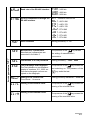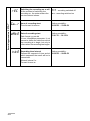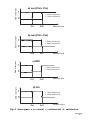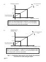
1
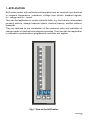
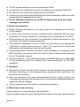
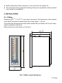
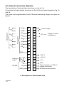
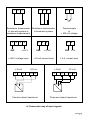
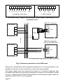
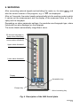
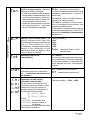
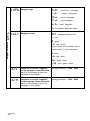
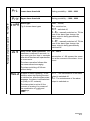
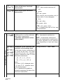
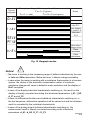
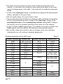
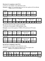
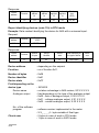
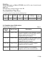
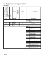
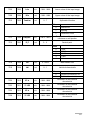
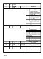
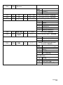
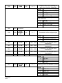
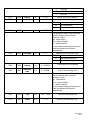
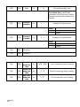
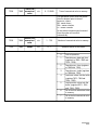
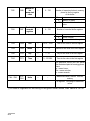
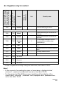
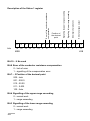
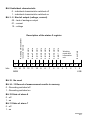
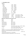
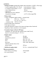
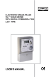
ONE-CHANNEL DIGITAL-TO-ANALOGUE METER WITH A MULTICOLOURED BARGRAPH AND A SERIAL INTERFACE NA5 TYPE USERS GUIDE One-channel digital-to-analogue meter with multicoloured bargraph and a interface NA5 TYPE USERS GUIDE CONTENTS Page 1. APPLICATION ............................................................................................ 5 2. SET OF THE METER ................................................................................. 6 3. BASIC REQUIREMENTS, OPERATIONAL SAFETY ................................ 7 4. INSTALLATION .......................................................................................... 9 5. SERVICING ............................................................................................. 13 6. RS-485 INTERFACE ................................................................................ 31 7. TECHNICAL DATA ................................................................................... 49 8. BEFORE A FAILURE HAS BEEN DECLARED ........................................ 53 9. EXAMPLES OF NA5 METER PROGRAMMING ..................................... 55 10. ORDERING PROCEDURE ...................................................................... 58 11. MAINTENANCE AND GUARANTEE ....................................................... 60 ! " 1. APPLICATION NA5 series meters with multicoloured bargraphs have an universal input destined to measure temperature, resistance, voltage from shunts, standard signals, d.c. voltage and d.c. current. They can find application in various industrial fields, e.g. food industry, intermediate pumping stations, sewage treatment plants, chemical industry, weather stations, breweries. They are destined for the visualisation of the measured value and evaluation of change trends of checked technological processes. They can also find application in automation systems where programmed controllers are applied. Fig.1. View of the NA5 meter. # NA5 meters can have in option: a continuous analogue output, a relay output, open collector (OC) type outputs and an RS-485 digital output. They are programmed by means of the keyboard and through RS-485. NA5 meters realise following functions: – measurement of the input quantity and displaying it on the display and the bargraphs, – recounting of the input signal into indication on the base of the individual linear characteristic, – arithmetical functions: raising to a power, extraction of roots, – programming of colours and bargraph resolutions, – signalling of alarm value setting exceedings, – recording of the measured signal in programmed time segments, – storage of maximal and minimal values, – programming of the measurement averaging time, – programming of the indication resolution, – deadlock of the parameter introduction by means of a password, – conversion of the measured quantity into a voltage or current output signal, – service of the RS-485 interface in MODBUS protocol, both in ASCII and RTU mode. 2. SET OF THE NA5 METER We deliver in the set: - NA5 meter - users guide - guarantee card - plug with screw terminals - holders to fix the meter in the panel - set of stickers with units 1 pc. 1 pc. 1 pc. 1 or 2 pcs (depending on execution) 2 pcs 1 pc. When unpacking the meter, please check whether the type and execution code on the data plate correspond to the order. $ 3. BASIC REQUIREMENTS, SAFETY INFORMATION Symbols located in this service manual mean: WARNING! Warning of potential, hazardous situations. Especially important. One must acquaint with this before connecting the NA5 meter. The non-observance of notices marked by these symbols can occasion severe injuries of the personnel and the damage of the instrument. ! CAUTION! Designates a general useful note. If you observe it, handling of the meter is made easier. One must take note of this when the instrument is working inconsistently to the expectations. Possible consequences if disregarded ! In the security scope the meter meets the requirements of the EEC Low-Voltage directive (EN 61010 -1 issued by CENELEC). ? Remarks concerning the operator safety: 1. General ! l The NA5 meter is destined to be mounted on a panel. l Non-authorized removal of the required housing, inappropriate use, incorrect installation or operation creates the risk of injury to personnel or damage to equipment. For more detailed information please see the users guide. l All operations concerning transport, installation, and commissioning as well as maintenance must be carried out by qualified, skilled personnel and national regulations for the prevention of accidents must be observed. l According to this basic safety information, qualified, skilled personnel are persons who are familiar with the installation, assembly, commissioning, and operation of the product and who have qualifications necessary for their occupation. 2. Transport, storage Please observe the notes on transport, storage and appropriate handling. Observe the climatic conditions given in Technical Data. 3. Installation l The NA5 meter must be installed according to the regulation and instructions given in this users guide. % l Ensure proper handling and avoid mechanical stress. l Do not bend any components and do not change any insulation distances. l Do not touch any electronic components and contacts. l Instruments may contain electrostatically sensitive components, which can easily be damaged by inappropriate handling. l Do not damage or destroy any electrical components since this might endanger your health! 4. Electrical connection l Before switching the meter on, one must check the correctness of connection to the network. l In case of the protection terminal connection with a separate lead one must remember to connect it before the connection of the instrument to the mains. l When working on live instruments, the applicable national regulations for the prevention of accidents must be observed. l The electrical installation must be carried out according to the appropriate regulations (cable cross-sections, fuses, PE connection). Additional information can be obtained from the users guide. l The documentation contains information about installation in compliance with EMC (shielding, grounding, filters and cables). These notes must be observed for all CE-marked products. l The manufacturer of the measuring system or installed devices is responsible for the compliance with the required limit values demanded by the EMC legislation. 5. Operation l Measuring systems including NA5 meters must be equipped with protection devices according to the corresponding standard and regulations for prevention of accidents. l After the instrument has been disconnected from the supply voltage, live components and power connections must not be touched immediately because capacitors can be charged. l The housing and the door must be closed during operation. 6. Maintenance and servicing Please observe the manufacturers documentation. Read all product-specific safety and application notes in this users guide manual & l Before taking the meter housing out, one must turn the supply off. l The removal of the instrument housing during the guarantee contract period may cause its cancellation. 4. INSTALLATION 4.1. Fitting Prepare a (44+0.5 x 137.5+0.5) mm hole in the panel. The thickness of the material from which the panel is made should be in the range 1...45 mm. The meter has screw terminal strips which enable the connection of 2.5 mm 2 crosssection external conductors. Meter dimensions are shown on the fig. 2. max 92 77 144 8 48 Fig. 2. Meter overall dimension ' 4.2. External connection diagrams The description of terminal strips are shown on the fig. 3a. Connections of input signals are shown on the fig 3b and output signals on fig. 3c and 3d. The meter has programmable inputs. Maximal measuring ranges are given on figures. A1 32 16 A2 31 15 A3 30 14 A4 29 13 A5 28 12 A6 27 11 A7 26 10 A8 25 9 24 8 23 7 22 6 ± 600 V 21 5 ± 40 mA 20 4 ±5A A 19 3 B 18 2 GND 17 1 A3 A5 8 OC outputs 4 rela outputs A1 A7 GND Analogue output RS-485 E Power supply 24 V d.c. GND Thermocouple or ± 300 mV voltage from shunt Resistance thermometer a/ Description of the terminal strip Supply of object transducers 1 2 3 1 2 2 3 3 - Resistance thermometer Resistance thermometer in two-wire system or in three-wire system resistance measurement 4 GND 5 6 3 ± 600 V GND ± 600 V voltage input ± 40 mA 3 4 5 3 ± 40 mA GND ± 5 A ± 40 mA current input 24 V d.c. 5 13 14 - - ± 5 A current input ± 40 mA 3 - 24 V d.c. 5 - 13 14 - - - 4 S 3 Thermocouple or ± 300 mV voltage - Two-wire object transducer Three-wire object transducer b/ Connection way of input signals 32 31 30 29 28 27 26 25 32 31 30 29 28 27 26 25 24 23 A1 A2 A3 A4 A5 A6 A7 A8 GND A1 8 outputs of OC type A3 A5 A7 4 relay outputs c/ Connection way of digital and analogue output signals depending on the execution code IBM PC computer A B GND NA5 Meter 19 10 11 12 13 18 17 GND RTS RxD TxD 6 1 DB9 9 5 ... PD5 B 8 A 9 IBM PC computer with an RS-485 card NA5 Meter 19 B 18 GND 6 1 A DB9 9 5 17 d/ Connection way of the RS-485 interface Fig.3 External connections of the NA5 meter Taking into consideration electromagnetic interference it is recommended to use shielded conductors for the connection of input and output signals. The power supply must be connected by means of a two-wire conductor with a suitable cross-section ensuring its protection by means of an installation fusible cut-out, in case of a short-circuit. Requirements concerning the supply cable are regulate by EN 61010-1 p.6.10 standard. 5. SERVICING After connecting external signals and switching the meter on, its name and also the current version of the program, e.g. n100. are displayed. After ca 3 seconds, the meter transits automatically into the working mode in which it carries out the measurement and the display of the measured value on the display and the bargraph. Depending on alarm parameter settings, the resolution and bargraph type, alarm thresholds are also displayed on the bargraph. The meter blanks automatically insignificant zeros. 55-element bargraph (in three-colour execution) 29-element bargraph (in seven-colour execution) Upper alarm threshold Lower alarm threshold Display Acceptation key Escape key Value increasing key Fig. 4 Description of the NA5 frontal plate. ! Key functions: - acceptation key - entry into the programming mode (hold down during ca 3 seconds), entry into the chosen parameter level, entry into the changing mode of the parameter value, acceptation of the changed parameter value. - Key to increase the value - display of the minimal value (first pressure), maximal (second pressure), return to measurement (third pressure), - mowing on the preview menu or programming matrix, - change of the chosen parameter value - increasing of the value. - Escape key - entry into the menu of recording results, entry into the preview menu or programming matrix, exit from the preview menu or programming matrix, escape from the parameter change. The pressure and hold down the key during 3 seconds causes the entry into the programming mode. The programming mode is protected by the seC safety code. The pressure and hold down the key during 3 seconds causes the entry into the preview menu and the menu of recorded values. One must move on the preview menu by means of the key. In this menu, only all programmed parame- ters except servicing parameters, are accessible to readout. The exit from the preview menu is operated by means of the possible in the preview menu to review recorded resl values. " key. It is also The pressure of the key on the resl parameter causes the entry into the preview menu of recorder values. The recorded result number is displayed alternately with the value e.g. n320/2174. The moving on recorded values follows by means of the key. The pressure of this key longer than ca 2 seconds will cause the acceleration of the review. The pressure of the key in any moment will cause the lighting of the number of recorded results. The exit from the review of recorded values is operated by means of the key. The algorithm of the meter servicing is presented on the fig. 5. # $ l Monitoring of recorded measured values l Monitoring of programmable meter parameters Moving on the preview menu Preview menu 3 sec Display of the inscription Password introduction mode Fig 5. Servicing algorithm of the NA5 meter. Erasing of alarm outputs 3 sec Display of the maximal value Measurement Display of the minimal value Incorrect Check the password Correct Programming matrix Moving on the matrix - Exit from the matrix - Entry into the selected level - Entry into parameter changes The appearance of the following symbols and inscriptions on the display means: ? Incorrectly introduced safety code Exceeding of the upper measuring range or lack of sensor Exceeding of the lower measuring range or short-circuited sensor Error of the conductor resistance compensation. No connected conductor or damaged conductor. It is possible to change meter parameters: - from the meter keyboard ( p 5.1) - through RS-485 (p.6.) 5.1. Change of the NA5 meter parameters from the keyboard The pressure of the of the seC. key during circa three seconds causes the display Inscription alternately with the set zero value by the manufacturer. The introduction of the correct code causes the entry into the programming mode. The fig.6 represents the transition matrix into the programming mode. One can move on groups of main parameters eg: Ch1, Ch2, bAr1, bAr2, Al1, Al2, etc, by means of the key. The pressure of the key on the given level, causes the entry into parameters of this level. The moving on the given level is operated by means of the key. In order to change the value, one must use the parameter change, one must press the By means of the key. In order to escape from the key. key, one can exit from the selected level and programming matrix to the measurement. % & 3 0ut ser l0gr 12 13 al8 ÷ al1 11 10 ÷ barg Chn 1 2 Main menu Lev. Nr colr Chan.1 record. date dat1 Chan.1 record. start gor1 Record. reC tst Test of display + bargr. seC Passw. change set Param. indiv. charac. Param. indiv. charac. Param. inscript. 0_y1 d_H1 :nd0 Alarm type typa brl Lower bargr. Input indiv. charac. prH Upper threshold Lower threshold Bargr. colour prl Bargr. type typb Hi:n func Con Cnt :nd: :_H: d_y: :_H2 d_y2 Decim. Meas. Input ind. Param. Param. Param. Param. point time charact. of ind. of ind. of ind. of ind. charact. charact. charact. charact. d_p Alarm Lower Upper support marker marker colour colour Baud rate Chan.1 record. interv. :nt1 Time Erasing Erasing change of min. of max. value value Hour Clrl ClrH Param. Param. of indiv. of indiv. charac. charac. Kind of transm. Device adress d_H2 0_y2 baud tryb adr Alarm delay dly H0ld Curl CurH brH Upper bargr. Lower value Upper value Mathem. Kind of of input range of input range func. comp. lo:n Input type typ Parameters of the selected level Fig. 6. Transition matrix into the programming mode Examples of value changing of the chosen parameter (parameter - symbol) 0000 000.0 00.00 0.000 Auto On Off Example of value changing of the chosen parameter without changing of the decimal point (number parameter) Blanking of insignificant zeros Change of the flickering position Change of the Change of the flickering position flickering position Change of the flickering position 0-9, -, -1 Example of value changing of the chosen parameter with changing of the decimal point (number parameter) Adjustment of the decimal point Change of the flickering coma Change of the flickering position Change of the Change of the Change of the flickering position flickering position flickering position 0-9, -, -1 Fig. 7. Meter programmable parameters are presented in the table 1. The programming of parameters is possible after the previous introduction of the password. ' Programmable parameters of NA5 meter Symbol on the display typ Parameter description Kind of input Table 1 Range of changes Reesistance thermometers: pt1 - Pt100 pt5 - Pt500 pt10 - Pt1000 Thermocouples: Input parameter Chn te-j - thermocouple, type J te-h - thermocouple, type K te-n - thermocouple, type N te-e - thermocouple, type E te-r - thermocouple, type R te-s - thermocouple, type S te-t - thermocouple, type T re2 - resistance to 10 kW napl - voltage to ± 300 mV napH - voltage to ± 600 V nnal - current to ± 40 mA nnaH - current to ± 5 A Lower value of the input range Setting possibility: -1999... 9999 At the input signal < LoIn the meter displays the lower exceeding. The condition narrow the measuring range down. Loln<Hiln must be fulfilled. The parameter does not take into consideration the individual characteristic, is operates on the measuring signal. setting of parameters LoIn lo:n The and HiIn gives the possibility to Upper value of the input range. Hi:n func Mathematical functions Setting possibility: -1999... 9999 At the input signal > HiIn the meter displays the upper exceeding. The condition Loln<Hiln must be fulfilled. The parameter does not take into consideration the individual characteristic, is operates on the measuring signal. 0ff - mathematical functions switched off; s)r - raising to a power (result)2 s)rt - extraction of roots Öresult Kind of compensation of sensor working conditions changes: - In case of a resistance thermometer and resistance measurement, it concerns the compensation of the resistance changes of the conductor linking the sensor with the meter, - In case of a thermocouple it concerns the compensation of reference junction temperature changes. auto - automatic compensation (in case of resistance thermometers and resistance measurement it requires a 3-wire line.) 0.0...60.0°C - value of the reference temperature for thermocouples. 0.0...40.0 W- resistance of two conductors for resistance thermometers and resistance measurement. The writing of a value beyond the interval of manual compensation (e.g. value 70.0) will cause the automatic compensation switching on. d_p Setting of the decimal point. The setting operates both when the individual characteristic is switched off and on. The introduction of the decimal point making impossible the display of four characters on the display will cause the display of the lower or upper exceeding. Setting possibility: 0000 000.0 00.00 0.000 Auto - automatic choice of the decimal point Cnt Averaging time of the measurement. 0.0...999.9 s The writing of 0 causes the switching of the measurement off and the stoppage of the meter operation. In this state, the meter displays the hour. The bargraph is blank. 1nd1 The switching off or on of the individual linear users characteristic. - (individual characteristic of the display). 0n - characteristic switched on, 0ff - characteristic switched off. 1_H1 d_y1 1_H2 d_y2 Parameters of the display individual characteristic. On the base of given by the user coordinates of two points the meter determines (from the system of equations) a and b coefficients of the individual characteristic. Input parameter Chn Con Setting possibility: -1999... 9999 d _ Y 1 = a ⋅ I _ H 1 + b d _ Y 2 = a ⋅ I _ H 2 + b Where: I_H1 i I_H2 - measured value d_Y1 i d_Y2 - expected value on the display. Fig.9 shows the way of the individual characteristic operation. typb Bargraph type 0neC - one colour bargraph, :ntr - interval bargraph, sect - sector bargraph, p:nt - point bargraph, tren -trend bargraph. colr Bargraph colour 0ff - bargraph switched off, r - red, g - green, Bargraph Parameters barg Fig. 10 explains bargraph types. . rg - red + green other colours are accessible only in meters with a 7-colour bargraph. b - blue, rb - red + blue, gb - green + blue, rgb - red + green + blue. brl Parameter to set the magnifier on the bargraph. Lower threshold. Value on the display at which the bargraph is to be blank. Setting possibility: -1999... 9999 brH Parameter to set the magnifier on the bargraph. Upper threshold. Value on the display at which the bargraph is to be lighted. Setting possibility: -1999... 9999 al1 to al8 Parameters of alarm 1 to alarm 8 prl Lower alarm threshold Setting possibility: - 1999... 9999 prH Upper alarm threshold Setting possibility: - 1999... 9999 typa Alarm type Fig. 8 shows alarm types nor - normal, 0n - switched on, 0ff - switched off, H_0n - manually switched on. Till the time of the alarm type change, the alarm output is being permanently switched on. H_0f - manually switched off. Till the time of the alarm type change, the alarm output is being permanently switched off. dly H0ld Delay of the alarm operation. The parameter is defined in seconds, i.e. one must give the time in seconds after which the alarm will operate after its occurrence. The alarm operation follows after the measurement averaging. The alarm switching off follows without delay.. 0.0... 999.9 Support of alarm signalling. In the situation when the holding function is switched on, after the alarm state stoppage, the alarm is still switched on (relay or OC contacts). The alarm state is active till the moment of erasing it by means of the combination of and keys. 0ff - The maintenance of the alarm Introduction of 0.0 causes the operation at the moment of the alarm occurrence. output is switched off. 0n - The maintenance of the alarm output is switched on. ! Curl Colour of the lower threshold alarm marker. CurH Colour of the upper threshold alarm marker. 0ff - alarm marker switched off. r - red, g - green, rg - red + green, Other colours are accessible only in meters with a 7-colour bargraph. b - blue, rb - red + blue, gb - green + blue, rgb - red + green + blue, Fig. 10 explains the idea of CurL and CurH parameters Output parameters 0ut :nd0 d-H1 0-y1 d-H2 0-H2 Switching off or on of the individual linear users characteristic (individual characteristic of the analog output). When the characteristic is switched off, the meter operates at the maximal range depending on input and range output. Parameters of the individual cha- Setting possibility: - 1999... 9999 racteristic of the analog output. On the base of given coordinates of two points by the user, the meter determines (from the equation system) coefficients a and b of the individual characteristic. O _ Y 1 = a ⋅ d _ H 1 + b O _ Y 2 = a ⋅ d _ H 2 + b where: d_H1 and d_H2 - displayed value O_Y1 and O_Y2 - expected value on the analog output. Fig. 9 represents the graphical illustration explaining the idea of the individual characteristic. " 0n - characteristic switched on, 0ff - characteristic switched off . ser Servicing parameters baud Baud rate of the RS-485 interface. 2400 - 2400 b/s 4800 - 4800 b/s 9600 - 9600 b/s tryb Kind of transmission through the RS-485 interface. 0ff - interface switched off a8n1 - ASCII 8N1 a7e1 - ASCII 7E1 a7o1 - ASCII 7O1 r8n2 - RTU 8N2 r8e1 - RTU 8E1 r8o1 - RTU 8O1 r8n1 - RTU 8N1 adr Device address Setting possibility: 0...247 set Manufacturers parameters. Manufacturers parameters are presented in the table 2. The pressure of the seC Introduction of a new password. Setting possibility: - 1999... 9999 tst Test of displays and bargraphs. The Test consists on a successive display of numbers 1111, 2222 etc. Successive bargraph colours are lighted on the bargraph. The pressure of the Hour Setting of the current time. Time format : hh:mm:ss Setting possibility: 00:00:00 ... 23:59:59 Clrl Erasing of the minimal value. The pressure of the ClrH Erasing of the maximal value. key causes the writing of manufacturers parameters. key causes the test switching on. The pressure of the key ends the test. key causes the erasing of the minimal value. The pressure of the key causes the erasing of the maximal value. # Switching the recording on or off. At the moment of switching the recording on, the meter erases the previous stored values. 0ff - recording switched off on - recording switched on go_r Hour of recording start Time format: hh:mm:ss Setting possibility: 00:00:00 ... 23:59:59 date Date of recording start Setting possibility: 70.01.01 ... 38.12.31 Date format: yy.mm.dd It is an information parameter. It not serves to define the date from which the recording is to begin, but only to inform when the recording has began. 1nte Recording time interval Setting possibility: Defines the segment of time and at 00:00:00 ... 99:59:59 which sequence the result will be to memorised. Minimal interval 1 s. Format: hh:mm:ss Recording parameters l0gr reC $ State of contacts a) nor (PrH > PrL) 1 1 - Relay switched on 0 - Relay switched off 0 State of contacts PrL State of contacts Measured value b) nor (PrH < PrL) 1 1 - Relay switched on 0 - Relay switched off 0 PrH PrL Measured value c) OFF 1 1 - Relay switched on 0 - Relay switched off 0 PrL State of contacts PrH PrH Measured value d) On 1 1 - Relay switched on 0 - Relay switched off 0 PrL PrH Measured value Fig. 8. Alarm types: a, b - normal, c - switched off, d - switched on % a) Displayed quantity Any characteristic slope d_Y2 d_Y1 Any displacement of the characteristic I_H1 I_H2 Measured quantity Value I_H1 on the meter input => value d_Y1 on the display. Value I_H2 on the meter input => value d_Y2 on the display other characteristic points are calculated b) Quantity on the analog output Any characteristic slope O_Y2 O_Y1 Any displacement of the characteristic d_H1 d_H2 Displayed value Value d_H1 on the display => value O_Y1 on the analogue output. Value I_H2 on the display => value O_Y2 on the analogue output other characteristic points are calculated Fig. 9. a) Individual characteristic of the display, b) Individual characteristic of the analogue output. & Type of bargraph Examplary settings of the bargraph and the alarm, ex. 1 Curl= G (green) Curl= r (red) Notes CurH= rG (red+green) 0neC Value under the value prl Value between prland prH Value ower prH :ntr sect p:nt Value without changes in time tren Value increases Value decreases Fig. 10. Bargraph modes. Notice! ? The meter is working in the measuring range of defined indications by the user in LoIn and HiIn parameters. Below and over, it shows a range exceeding. In case when the meter is working with a resistance thermometer in a two-wire system, the choice of the automatic compensation option of conductor resistance changes will cause a defective meter operation and the display of ErrC inscription. In case of the display individual characteristic switching on, the result on the display is linearly converted according the introduced parameters: I_H1, I_H2, d_Y1 and d_Y2. In case of arithmetical functions and individual characteristic switching on, in the first sequence, arithmetical operations will be carried out and the obtained result is converted by the individual characteristic. In case of the analog output individual characteristic switching on, the measurement result is linearly converted according to the introduced parameters: d_H1, d_H2, O_Y1 i O_Y2. ' The meter currently checks the value of the introduced parameter at the moment. In case when the introduced value exceeds the upper or the lower range of changes given in the table 1, the meter will not make the parameter record. In case of the Input type change, a simultaneous change of the decimal point follows, optimally for the given input. After the supply decay, the current time is reset. The recording switching off follows in following cases: switching the recording off from the programming matrix, change of the input type, change of the recording time start or the recording time interval, setting Cnt=0, filling of the memory, and at a renewed switching of the meter on to the network. In case of a Intr or Sect bargraph type, it is possible to set only one CurL and Curh markers (from one alarm). The others are automatically erased. Max and Min values are erased in case of changes: input type, individual characteristic (on, off), writing of standard parameters. Standard parameters of the NA5 meter Table 2 Parameter description Standard value Parameter description Standard value typ lo:n Hi:n func Con d_p Cnt :nd: :_H1 d_y1 :_H2 d_y2 typb colr brl brH nnal (± 40 mA) prl prH typa dly H0ld Curl - 20.00 ! - 20.0 20.00 OFF 0 = manually 00.00 1.0 OFF 0 Sect G - 20.0 20.00 20.00 OFF 0 OFF r - Alarm 1 and 3 OFF-other alarms CurH rG - Alarm 1 and 3 OFF-other alarms :nd0 d_H1 0_y1 d_H2 0_y2 baud tryb OFF 0 9600 RTU 8N2 adr seC Hour reC gor_r 1 0 date :nte 70:01:01 00:15:00 00:00:00 OFF 00:00:00 6. RS-485 INTERFACE NA5 programmable digital meters have a serial link of RS-485 standard to communicate in computer systems and with other devices fulfilling the master function. The MODBUS asynchronous character communication protocol has been implemented on the serial link. The transmission protocol describes information exchange procedures between devices through the serial link. 6.1. Procedure of the serial interface connection The RS-485 standard enables the direct connection to 32 devices on a single serial link up to a 1200 m distance. For the connection of a higher number of devices it is necessary to apply additional intermediate-to-separating systems. The exit of the interface line is presented in the service manual on the fig. 3.d. In order to obtain a correct transmission it is necessary to connect lines A and B in parallel to their equivalent lines in other devices. The connection must be made with a shielded conductor. The shield must be connected to the protective terminal in one point. The GND line serves to the additional protection of the interface line at long distance connections. One must connect GND signals between devices and in one point to the protective terminal (that is not necessary for the interface correct operation). To obtain the connection with the computer of IBM PC class, an RS-232 into RS-485 converter is necessary or an RS-485 interface card. The way of NA5 meter connection through the PD5 converter is shown on the fig. 3d. The designation of transmission lines for the card in the PC computer depends on the card producer. ! 6.2. Description of the MODBUS protocol implementation The implemented protocol is compatible with the PI-MBUS-300 Rev G Modicon Company specification. Set of serial link parameters of meters in the MODBUS protocol: l meter address - 1... 247 l baud rate - 2400, 4800, 9600 bit/s l working mode - ASCII, RTU l information unit - ASCII: 8N1, 7E1, 7O1 - RTU: 8N2, 8N1, 8E1, 8O1 l maximal response time 500 ms The configuration of serial link parameters is described in the further part of the users manual. It consists on the establishment of the baud rate (bAud parameter), device address (Adr parameter) and the type of information unit (trYb parameter). Note: Each meter connected to the communication network must have: l a unique address, different from addresses of other devices connected in the network, l an identical baud rate and information type. 6.3. Description of the MODBUS protocol functions Following functions of the MODBUS protocol have been implemented in NA5 meters: Function description Code 03 (03 h) 06 (06 h) 16 (10 h) 17 (11 h) Table 3 Meaning Read-out of n-registers Recording of a single register Recording of n-registers Identification of the slave device The maximal number of registers for writing or readout by one order is equal 28. ! Read-out of n-registers (code 03 h) Function is inaccessible in the publication mode. Example: readout of 2 registers beginning from the register with the address 1 DBDh (7613) in RTU mode. Request: Device address Function 01 03 Register address Hi 1D Register address Lo BD Number of registers Hi 00 Number of registers Lo 02 Checksum CRC 52 43 Response: Device address Function Number of bytes 01 03 08 Value from the register 1DBD (7613) 3F 80 00 00 Value from the register 1DBE (7614) 40 00 00 00 Checksum CRC 42 8B Record of values into the register (code 06h) The function is accessible in the publication mode. Example: record of the register of 1DBDh (7613) address in RTU mode. Request: Device address Function 01 06 Register address Hi 1D Register address Lo BD Register address Hi 1D Register address Lo BD Value from the register 1DBD (7613) 3F 80 00 00 Checksum CRC 85 AD Response: Device address Function 01 06 Value from the register 1DBD (7613) 3F 80 00 00 Checksum CRC 85 AD Device address Function Record into n-registers (code 10h) The function is accessible in the publication mode Example: record of two registers beginning from the register with 1DBDh (7613) address in RTU mode. Request: 01 10 Register address Hi Lo 1D BD Number of registers Hi Lo 00 02 Number Value for the register Value for the register of bytes 1DBD (7613) 1DBE (7614) 08 3F 80 00 00 40 00 00 00 Checksum CRC 03 09 !! Response: Device address Function Register address Hi Register address Lo 01 10 1D BD Number of Number of registers registers Hi Lo 00 02 Checksum (CRC) D7 80 Report identifying devices (code 11h) in RTU mode Example: Data readout identifying the device for NA5 with a universal input. Request: Device address Function 01 11 Checksum (CRC) C0 2C Response: Device address Function Number of bytes Device identifier Device state Field depending on the type of device 01 11 08 81 FF 00XXXXX Device address - depending on the setpoint Function - no of function 0x11 Number of bytes - 0x08 Device identifier - 0x81 Device state - 0xFF Field depending on the device type - XXXXXX Device name - no taken advantage in NA5 meters, 00 X X X X X Analogue output - field depending on the type of the analogue output - 0x00 - lack of analogue output, X 00 X X X X - 0x01 - voltage analogue output, X 01 X X X X - 0x02 - current analogue output, X 02 X X X X No. of the software program Check sum !" Checksum - software version implemented in the meter - X X_ _ _ _4 - byte variable of float type - 2 bytes in case of work in RTU mode - 1 byte in case of work in ASCII mode Example: Work in RTU mode: e.g. Mode = RTU 8N2 (value 0x02 in case of readout/record through the interface). NA5 meter Execution with a voltage analogue output: 00, No. of the software version: 1.00, Device address set on: Adr = 0 x 01, For such a meter the frame has the following form: Device address Function Number of bytes Device identifier Device state Field depending on the device type Checksum (CRC) 01 11 08 81 FF 00 00 3F 80 00 00 FE D7 6.4. Register map of NA5 meters Register map of NA5 meters Table 4. Address range Type of value Description 7000-7200 Float (32 bits) The value is placed in two successive 16-byte registers. Registers enclose the same data as 32-byte registers from the 7500 area. Registers are only for readout. 7200-7400 Float (32 bits) The value is placed in two successive 16-bit registers. Registers enclose the same data as 32-bit registers from the 7600 area. Registers are only for readout. 7500-7600 Float (32 bits) The value is placed in a 32-byte register. Registers are only for readout. 7600-7700 Float (32 bits) The value is placed in a 32-bit register. Registers can be read out and recorded. !# 6.5. Registers for recording and readout The value is placed in 32-bit registers 7200 7600 Symbol Identifier Writing (w) Readout (r) The value is placed in two successive 16-bit registers enclosing the same data as 32-bit registers from the 7600 area NA5 meter r Range Description - Device identifier Value 81 7202 7601 Channel number w/r 0...1 7204 7602 input w/r 0...14 No occurs Channel input type <Channel number> Value 0 !$ NA5 Pt100 RTD 1 Pt500 RTD 2 Pt1000 RTD 3 J thermocouple 4 K thermocouple 5 N thermocouple 6 E thermocouple 7 R thermocouple 8 S thermocouple 9 T thermocouple 10 R. meas. up to 10 kW 11 Volt. meas. to ± 300 mV 12 Volt. meas. to ± 600 V 13 Current meas. to ± 40 mA 14 Current meas. to ± 5 A 7206 7603 LoIn w/r -1999... 9999 Lower value of the input range 7208 7604 HiIn w/r -1999... 9999 Upper value of the input range 7210 7605 Function w/r 0... 7 Arythmetical function Value 0 Switched off 1 Squaring 2 Extraction of roots 7212 7606 Compens. w/r -199.9... 999.9 Compensation of the conductor resistance or cold junction 7214 7607 D_P w/r 0... 4 Decimal point Value 0 1 2 3 4 7216 7608 Cnt w/r 0... 999.9 7218 7609 Indi w/r 0... 1 0000 000.0 00.00 0.000 Auto Measurement time Individual characteristic Value 0 1 Switched characteristic off Switched characteristic on 7220 7610 X1 In w/r -1999... 9999 Parameters of the individual characteristic 7222 7611 Y1 LED w/r -1999... 9999 Parameters of the individual characteristic 7224 7612 X2 In w/r -1999... 9999 Parameters of the individual characteristic 7226 7613 Y2 LED w/r -1999... 9999 Parameters of the individual characteristic !% 7228 7230 7614 No occurs 7615 Bargraph type w/r Bargraph type 0... 4 Value 0 1 2 3 4 7232 7616 Colour w/r 0... 7 One-colour (OnEC) Change of colour after exceeding the alarm threshold (the colour change the whole bargraph) (Intr) Change of colour after exceeding the alarm threshold (Three-segment change of colour) (SEct) One-colour bargraph, alarm markers in another colour (PInt) Increasing/decreasing trend (trEn) Bargraph colour Value 0 Bargraph off (OFF) 1 Red (r) 2 Green (G) 3 Red + Green (rG) Other values are only accessible in meters with RGB diodes 4 5 6 7 Blue (b) Red + Blue (rb) Green + blue (Gb) Red + Green + Blue (rGb) 7234 7617 Brl w/r -1999... 9999 Magnifier on the bargraph Lower threshold 7236 7618 Brh w/r -1999... 9999 Magnifier on the bargraph Upper threshold 7238 7619 Alarm number w/r 0... 7 Choice of alarm number Range of changes is depended on the meter execution code (number of alarms) !& 7240 7620 No occurs Value 0 1 Channel 1 Channel 2 7242 7621 Prl w/r -1999... 9999 Alarm lower threshold <Alarm No> 7244 7622 Prh w/r -1999... 9999 Alarm upper threshold <Alarm No> 7246 7623 Type a w/r 0... 4 Alarm type <Alarm No> Value 0 1 2 3 4 Normal Switched on Switched off Manually switched on Manually switched off 7248 7624 Alarm delay w/r 0... 999.9 Alarm delay <Alarm No> 7250 7625 Alarm support w/r 0... 1 Alarm signalling support <Alarm No> Value 0 1 7252 7626 CURL w/r 0... 7 Support switched off Support switched on Bargraph colour to the lower alarm threshold < Alarm Nr > Value 0 Bargraph switched off (OFF) 1 Red (r) 2 Green (G) 3 Red + Green (rG) Other values accessible only in meters with RGB diodes 4 Blue (b) 5 Red + Blue (rb) 6 Green + blue (Gb) 7 Red + Green + Blue (rGb) !' 7254 7627 CURH w/r 0... 7 Bargraph colour after exceeding the upper alarm threshold <Alarm No> Value 0 Bargraph switched off (OFF) 1 Red (r) 2 Green (G) 3 Red + Green (rG) Other values accessible only in meters with RGB diodes 4 Blue (b) 5 Red + Blue (rb) 6 Green + blue (Gb) 7 Red + Green + Blue (rGb) 7256 7628 No occurs 7258 7629 Output characteristic w/r 0... 1 Characteristic of the analogue output Value 0 1 Characteristic switched off Characteristic switched on 7260 7630 X1 LED w/r - 1999... 9999 Parameters of the analogue output characteristic 7262 7631 Y1 Out w/r - 1999... 9999 7264 7632 X2 LED w/r - 1999... 9999 Parameters of the analogue output characteristic Parameters of the analogue output characteristic 7266 7633 Y2 Out w/r - 1999... 9999 7268 7634 Baud rate w/r 0... 2 Parameters of the analogue output characteristic Baud rate of the RS-485 interface Value 0 1 2 7270 7635 Working mode w/r 0... 7 Working mode of the MODBUS protocol Value 1 2 3 4 " 2400 bit/s 4800 bit/s 9600 bit/s ASCII 8N1 ASCII 7E1 ASCII 7O1 RTU 8N2 5 6 7 7272 7636 Address w/r 0... 247 7274 7637 Test w/r 0... 1 Choice of the device address Test of the display Value 0 1 7276 7638 Hour w/r RTU 8E2 RTU 8O2 RTU 8N1 0... 23.5959 Lack of operation Test Current time This parameter occurs with four places after the decimal point in format gg,mmss, where: gg - means hours, mm - means minutes, ss - means seconds In case when introducing and incorrect time, the indicator will correct it automatically. 7278 7639 Recording w/r 0... 1 Registration of measured value Value 0 1 7280 7640 Interval w/r 0... 99.5959 7282 7642 Recording time w/r 0... 23.5959 Recording switched off Recording switched on Time interval of the recording Time of the recording start This parameter occurs with four places after the decimal point in format gg,mmss, where: gg - means hours, mm - means minutes, ss - means seconds In case when introducing and incorrect time, the indicator will correct it automatically. 7284 7642 Year w/r 1970... 2038 Year of the recording start 7286 7643 Month w/r 1... 12 Month of the recording start " 7288 7644 Day w/r 1... 31 Day of the recording start Year, Month, Day are information parameters (they do not serve to define the date from which the recording is to be start). 7290 7645 Erasing of minimum w/r 0... 1 Erasing of the minimal value Value 0 1 7292 7646 Erasing of maximum w/r 0... 1 Erasing of the maximal value Value 0 1 " Lack of operation Erasing Lack of operation Erasing 7294 7647 No occurs 7296 7648 No occurs 7320 7660 Year of the memorised value w/r 1970... 2038 Year of memorised value in memory 7322 7661 Month of the memorised value w/r 1... 12 Month of memorised value in memory 7324 7662 Day of the memorised value w/r 1... 31 Day of memorised value in memory 7326 7663 Time of the memorised value w/r 0... 23.5959 Time of memorised value in memory This parameter occurs with four places after the decimal point in format gg,mmss, where: gg - means hours, mm - means minutes, ss - means seconds In case when introducing and incorrect time, the meter will correct it automatically. 7328 7664 Index of the memorised value w/r 1... 750 Number of memorised value in memory 7230 7665 Status w/r 0... 7 Operation status on the buffer Value 0 Lack of operation 1 Searching acc. date and time (registers nr 7660...7663 and 7320...7326) 2 Searching acc. time (registers nr 7663 and 7326) 3 Searching acc. index (registers nr 7664 and 7328) 4 Load next values into the buffer (registers7672...7691and 7344...7382) 5 Load previous values into the buffer (registers7672...7691 and 7344...7382) 6 Go to the first memorised value in memory. 7 Go to the last memorised value in memory. "! 7332 7666 Number of the memorised value r 0... 750 Number of memorised value in memory, placed in the first register of the buffer Value 0 Memory is empty 1... 750 Number of the memorised value 7334 7667 Number of recorded registers r 0... 750 Number of recorded buffer registers Value 0 Buffer is empty 1... 750 Number of recorded registers 7336 7668 Year r 1970... 2038 Year for the value in the first register 7338 7669 Month r 1... 12 Month for the value in the first register 7340 7670 Day r 1... 31 Day for the value in the first register 7342 7671 Time r 0... 23.5959 Time for the value in the first register This parameter occurs with four places after the decimal point in format gg,mmss, where: gg - means hours, mm - means minutes, ss - means seconds 7344...7382 7672... 7691 Buffer r Memorised values, read off from the memory 20 registers , including 20 memorised values. 1) In case of registers not occurring in the given meter series, their value is:1E+20 "" The value is placed into 32-bite registers 7000 7500 Identifier r - Constant identifying the device 7002 7501 Status 1 r - Register describing the current state of the meter 7004 7502 Status 2 r - Register describing the current state of the meter 7006 7503 Steering out r % It is the register defining the control procedure of the analogue output (controllability) 7008 7504 Min 1 r - Minimal value of the currently measured value 7010 7505 Max 1 r - Maximal value of the currently measured value - Name Writing (w) Readout (r) The value is placed into two successive 16-bite registers. These registers include the same data as 32-bite registers from the area 7500. 6.6. Registers only for readout 7012 7506 Value 1 - 7014 7507 Hour - 7016 7508 No occurs 7018 7509 No occurs 7020 7510 No occurs Unit Quantity name Currently measured value Current time 1) In case of registers no occurring in the given meter series, their values is 1E+20 Note ! At the moment of exceeding the upper or lower range, displayed value, minimum, maximum parameters are set on the value 1E+20. For the parameter Cnt=0 (Measurement switching off and display of the current time), minimum, maximum and displayed value parameters are set on the value 1E+20. "# X X X X X X X X X 15 14 13 12 11 10 9 8 7 6 5 4 3 2 1 X bits X X X X Position of the decimal point MSB Bit-15... 9 No used Bit-8 Error of the conductor resistance compensation 0 - lack of error 1 - signalling of the compensation error Bit-7... 5 Position of the decimal point 000 - lack 001 - 000.0 010 - 00.00 011 - 0.000 100 - Auto Bit-4 Signalling of the upper range exceeding 0 - normal work 1 - range exceeding Bit-3 Signalling of the lower range exceeding 0 - normal work 1 - range exceeding "$ Kind of analogue output Signalling of lower range exceeding Individual characteristic X Error of the conductor resistance compensation Signalling of upper range exceeding Description of the Status 1 register X 0 LSB Bit-2 Individual characteristic 0 - individual characteristic switched off 1 - individual characteristic switched on Bit-1...0 Kind of output (voltage, current) 00 - lack of analogue output 01 - current 10 - voltage Alarm 4 state Alarm 3 state Alarm 2 state Alarm 1 state X X X X X X X X Working mode and information unit Baud rate Alarm 5 state X Alarm 6 state X Alarm 7 state X bits Alarm 8 state Recording of measurement results in memory Description of the status 2 register X X X X 15 14 13 12 11 10 9 8 7 6 5 4 3 2 1 MSB X 0 LSB Bit-15. No used Bit-14...13 Record of measurement results in memory 0 - Recording switched off 1 - Recording switched on Bit-12 State of alarm 8 0 - off 1 - on Bit-11 State of alarm 7 0 - off 1 - on "% Bit-10 State of alarm 6 0 - off 1 - on Bit-9 State of alarm 5 0 - off 1 - on Bit-8 State of alarm 4 0 - off 1 - on Bit-7. State of alarme 3 0 - off 1 - on Bit-6 State of alarm 2 0 - off 1 - on Bit-5 State of alarm 1 0 - off 1 - on Bit-4...2 Working mode and information unit 000 - interface switched off 001 - 8N1 - ASCII 010 - 7E1 - ASCII 011 - 7O1 - ASCII 100 - 8N2 - RTU 101 - 8E1 - RTU 110 - 8O1 - RTU 111 - 8N1 - RTU Bit-1...0 Baud rate 00 - 2400 bit/s 01 - 4800 bit/s 10 - 9600 bit/s "& 7. TECHNICAL DATA INPUTS: Pt100 Pt500 Pt1000 J (Fe-CuNi) K (NiCr-NiAl) N (NiCrSi-NiSi) E (NiCr-CuNi) R (PtRh13-Pt) S (PtRh10-Pt) T (Cu-CuNi) Resistance measurement Voltage measurement Voltage measurement Current measurement Current measurement (- 200... + 850)°C (- 200... + 850)°C (- 200... + 850)°C (- 100... + 1100)°C (-100... + 1370)°C (- 100... + 1300)°C (- 100... + 850)°C (0... + 1760)°C (0... + 1760)°C (- 50... + 400)°C 0... 10 kW ± 300 mV, input resistance > 9 MW, ± 600 V, input resistance > 4.2 MW ± 40 mA, input resistance < 4 W 0... ± 5 A, input resistance = 10 mW ± 10% Measuring subranges (preserving the class): Pt100 320°C Pt500 230°C Pt1000 290°C Thermocouple J 350°C, 700°C Thermocouple K 450°C, 950°C Thermocouple N 550°C, 1000°C Thermocouple E 250°C, 520°C Resistance 110 W, 220 W, 460 W, 950 W, 2100 W, 5000 W Voltage 19 mV, 35 mV, 75 mV, 155 mV, 5 V, 11 V, 22 V, 45 V, 90 V, 180 V, 360 V Current: 5 mA, 11 mA, 23 mA, 1.8 A, 3.8 A Intensity of current flowing through the resistance thermometer: < 400 mA Resistance of conductors linking the resistance thermometer with the meter: < 20 W/1 wire Thermocouple characteristics acc. EN 60584-1. Resistance thermometer characteristics acc. IEC 751+A1+A2. "' OUTPUTS: Analogue outputs galvanically isolated, with a resolution = 0,025% of the range - current programmable: 0/4...20 mA load resistance £ 500 W - or voltage programmable: 0...10 V load resistance ³ 500 W - output response time 100 ms - output error 0.2% of the range - additional error due to ambient temperature changes: ± (0.1% of the range/10K) Relay output 4 relays; voltageless make contacts - maximal load: voltage 250 V a.c., 150 V d.c., current 5 A 30 V d.c., 250 V a.c., resistance load 1250 VA, 150 W. Programmable alarm thresholds; Three types of alarms; Hysteresis defined by means of the lower and upper alarm threshold; Signalling of alarm operation on the bargraph; 8 outputs of open collector (OC) type voltageless, OC type with npn transistor (max. load 25 mA) range of connected voltage: 5...30 V d.c. Digital output: interface: transmission protocol: ASCII: RTU: baud rate: maximal response time to the request frame: RS-485, MODBUS, 8N1, 7E1, 7O1, 8N2, 8E1, 8O1, 8N1, 2400, 4800, 9600 baud 500 ms. Additional supply output 24 V d.c., maximal load 30 mA Memory parameters: - meter memory (recording) - min. record interval 750 samples 1 sec; # Basic error: 0.1% of measuring range ±1 digit 0.2% of measuring range ±1 digit (for thermocouples R, S, T) Additional errors in nominal working conditions when measuring the temperature: - compensation of reference junction temperature changes ± 1°C - compensation of conductor resistance changes ± 0.1% of the range - from ambient temperature changes ± (0.05% of the range/10K) Averaging time Rated operation conditions: - supply voltage depending on the execution code - supply a.c. voltage frequency ambient temperature storage temperature relative humidity pre-heating time Sustained overload: - thermocouples, resistance thermometers - measurement of voltage, current and resistance Momentary overload (3 s): - sensor and voltage inputs 300 mV - voltage input > 2,5 V - current input min 200 ms min 500 ms (temperature ranges) 95...230...253 V a.c./d.c. 20...24...40 V a.c./d.c. 40...50/60...440 Hz - 10...23...55°C - 25...+85°C < 95% (no condensation) 10 min. (for thermocouples with automatic compensation switched on: 1 hour) 1% 10 % 10 V 10 ´ Un (< 1000 V) 10 ´ In # Readout field (depending on execution): 2 x 4 LED seven-segment LED display, character height: 7 mm indication range: -1999...9999 bargraph length: 88 mm - 55 segments in three-colour execution - 29 segments in seven-colour execution Bargraph resolution programmable Bargraph accuracy ± 0.5 segment Servicing three keys: Ensured protection degree: - through the casing - from terminal side IP 50 IP 20 Overal dimensions 48 x 144 x 100 mm (with terminals) Weight: < 0.4 kg Power consumption < 13 VA Resistance against supply decay: acc. EN 61000-6-2 Electromagnetic compatibility: - immunity - emission EN 61000-6-2 EN 61000-6-4 (industrial environment) Safety requirements according EN 61010-1: - installation category III - pollution degree 2 - phase-to-earth max. working voltage: - input 600 V - supply 300 V - relays 300 V - analogue output 50 V - RS-485 50 V # 8. BEFORE A FAILURE WILL BE DECLARED In case of incorrect symptoms please to acquaint with the table below. SYMPTOMS ? PROCEDURE 1. Lack of indications on the display. The bargraph indicates nothing. Check the connection of the feeder cable. 2. The time is displayed on the display, e.g. H_12 alternately with 34:43. The number of measurements Cnt = 0 has been introduced. The meter is working in the SLEEP mode. It displays the current hour. 3. Marks or are displayed on the display. Check the correctness of the input signal connection. See the service manual. Check also the setting of parameters D_P, Ind, Loln and Hiln. 4. A signal inconsistent with our expectations occurs on the meter analog output. One must check if the load resistance of the analogue output is in accordance with technical data. Check if the individual characteristic is not switched on. In case of necessity make changes of individual characteristic parameters or introduce manufacturer parameters Set. 5. Lack of possibility to enter into the programming mode. The inscription Err is displayed. The programming mode is protected by a password. When the user forgets which password has been introduced, he should contact by phone the manufacturer or the nearest authorised workshop. 6. Lack of certainty if all segments of the display or bargraph are efficient. Enter into the programming matrix and switch the display and bargraph tSt test on. Character fields are lighted successively from 0000 to 9999. In the same time the bargraph is lighted with successive colours. If some of segments are not lighted or diodes have different colours, one must submit these defects to the nearest workshop. 7. During the operation in the programming mode, parameter values inconsistent with the range of changes given in the table 1, appear on the display. Enter into the programming matrix and accept the SEt parameter. The meter will introduce values in accordance with the table 2. #! 8. A result inconsistent with our expectations appears on the display. Check if the individual characteristic is not switched on. In case of necessity enter into the programming matrix and accept the SEt parameter. The meter will introduce parameters in accordance with the table 2. 9. The bargraph does not work in accordance with our expectations. Check bargraph parameters. In case of a further incorrect operation, enter into the programming matrix and accept the parameter SEt. Switch the display and bargraph tSt test on. 10. Despite the exceeding of the alarm threshold the alarm relay does not switch on. Check the delay of alarm operation introduced into the meter. In case of need, correct the dLY parameters. 11. The meter, instead of displaying the measurement result, displays the parameter symbol and its value. The meter is working in the preview mode or in the 12. Despite of the introduced delay in the alarm operation, e.g. 30 seconds, the alarm after this time did not operate. The lasting alarm state was shorter than the programmed, that means that during the lasting time, the alarm withdrawal state occurred. In such a case, the meter begins to count down the time from the beginning. 13. The meter does not establish the communication with the computer through the RS-485 interface. Check if interface conductors (A, B, GND) were correctly connected. Then, check in the programming matrix the setting of the interface (bAud, trYb, Adr). These parameters must be the same as in the used software. #" programming mode. Press the escape key . 9. EXAMPLES OF NA5 METER PROGRAMMING Example 1. Programming of the individual characteristic. If we want to programme so that to the value 4.00 mA will correspond the value 0 on the display, whereas the value 100, to the value 20.00 mA, one must: l enter into the programming mode and choose the D_ P parameter responsible for the decimal point. Set the decimal point on 00000 l choose the Ind parameter and switch the individual characteristic On l choose the I_H1 parameter and introduce the value 4.00 l transit on the d_Y1 parameter and introduce the value 0 l transit on the I_H2 parameter and introduce the value 20.00 l transit on the d_Y2 parameter and introduce the value 100 Example 2 Programming of an inverse individual characteristic. If we want to programme so that to the value 4.00 mA will correspond the value 120.5 on the display, and the value 10.8, to the value 20.00 mA, one must: l enter into the programming mode and choose the D_P parameter responsible for the decimal point. Set the decimal point on 0000.0 l choose the Ind parameter and switch the individual characteristic On l choose the I_H1 parameter and introduce the value 4.00 l transit on the d_Y1 parameter and introduce the value 120.5 l transit on the I_H2 parameter and introduce the value 20.00 l transit on the d_Y2 parameter and introduce the value 10.8 Example 3 Programming of the alarm with hysteresis If we want to programme the alarm 1 operation so that at the value 850°C, this alarm will be switched on, whereas it will be switched off at the value 100°C, and the alarm 2 operation so that at the value 1000°C this alarm will be switched off and switched on at the value -199°C, one must: l enter into the programming mode, choose the PrL parameter of the alarm 1 and introduce the value 100 l transit on the PrH parameter of the alarm 1 and introduce the value 850 l transit on the tYPA parameter of the alarm 1 and choose select the function assigned as nor l enter into the programming mode and choose the PrL parameter of the alarm 2 and introduce the value 1000 l transit on the PrH parameter of the alarm 2 and introduce the value -199 l transit on the tYPA parameter of the alarm 2 and select the function nor ## Example 4 Programming of an alarm operating in a set interval with delay. If we want that the alarm 1 will be switched on in the interval from 100 V to 300 V and operate only after 10 seconds, one must: l enter into the programming mode, choose the PrL parameter of the alarm 1 and introduce the value 100 l transit on the PrH parameter of the alarm 1 and introduce the value 300 l transit on the tYPA parameter of the alarm 1 and select the function On l transit on the dLY parameter of the alarm 1 and introduce the value 10.0 in case of the alarm state duration for a time longer than 10 seconds, the meter will switch the alarm relay on Example 5 Programming of an analog output If we want to programme so that to the displayed value 0.00 mA will correspond the value 4.00 on the analogue output, whereas to the value 20.00 mA , the value 20.00 mA, one must: l enter into the programming mode, choose the IndO parameter and switch the individual characteristic On l choose the d_H1 parameter and introduce the value 0.00 l transit on the O_Y1 parameter and introduce the value 4.00 l transit on the d_H2 parameter and introduce the value 20.00 l transit on the O_Y2 parameter and introduce the value 20.00 Example 6 Bargraph programming If we want to programme so that the bargraph was of a ,,sector type - red colour between PrL and PrH parameters, one must: l enter into the programming mode , choose the tYPb parameter of the bargraph and choose SEct l choose the coLr parameter of the bargraph 1 and choose r Example 7 Programming a bargraph with a ,,magnifier If we want to programme so that the bargraph was blank for the value 0 and full lighted for the value 150, one must: l enter into the programming mode , choose the brL parameter of the bargraph and introduce the value 0 l choose the brH parameter of the bargraph 1 and introduce the value 150 #$ Example 8 Programming of recording every 20 sec from 12:30 l enter into the programming mode, choose the Go_r parameter and introduce the value 12:30, l transit into IntE parameter and introduce the value 00:00:20, l choose the rEc parameter and switch the recording in On, l after exiting from the programming matrix, the memory will be erased and the meter will begin recording results evry 20 sec, from 12:30. After filling the memory, the recordingwill be switching off. #% 10. ORDERING PROCEDURE NA5 METER WITH BARGRAPH Table 5 X X X X X X X X XX X Bargraph colour: 3 colours (R, G, R + G) .................................... T 7 colours (R, G, B, R+G, R+B, G+B, R+G+B) ... M Display colour: without display* ...................................................... 0 red ........................................................................... R green ....................................................................... G blue ......................................................................... B Input signal: universal input (table 6) .................................................. U on order** ..................................................................... X Analogue output signal: without output ........................................................................ 0 current programmed, 0/4...20 mA .......................................... 1 voltage programmed, 0...10 V ................................................ 2 on order** ............................................................................. X Digital output signal: without output ................................................................................ 0 RS-485 digital output ..................................................................... 1 Additional outputs: without output ....................................................................................... 0 4 relays outputs ..................................................................................... 4 8 OC outputs ......................................................................................... 8 on order** ............................................................................................ X Supply: 95...253 V a.c./d.c. ........................................................................................ 1 20... 40 V a.c./d.c. ......................................................................................... 2 on order** .................................................................................................... X Kind of terminals: socket - screw plug .............................................................................................. 0 on order*** ......................................................................................................... X Execution: standard ...................................................................................................................... 00 custom-made** .......................................................................................................... XX Acceptance test: without a quality inspection certificate ................................................................................ 0 with an extra quality inspection certificate ........................................................................... 1 according customers agreement ** ................................................................................... X Notes: #& *) In the meter without displays, one must order the RS-485 digital output execution. **) The manufacturer assigns the execution code. ***) Available execution with self-locking sockets. Example of NA5 ordering: Code: NA5 M G U 1 1 4 1 0 00 0 means: M - NA5 meter with two 7-colour bargraphs, G - digital LED displays of green colour, U - universal input (table 6), 1 - current analogue output signal 0/4...20 mA, 1 - RS-485 digital output signal, 4 - additional outputs consisting of 4 relays, 1 - supply: 95...253 V a.c./d.c., 0 - socket-screw plug terminals, 00 - standard execution, 0 - without a quality inspection certificate. In case of a custom-made execution or if you need some more additional technical information, please write to or phone our Export Department. Input signals Universal input Table 6 Resistance thermometer: Pt100 Pt500 Pt1000 Thermocouple: J (Fe-CuNi) K (NiCr-NiAl) N (NiCrSi-NiSi) E (NiCr-CuNi) R (PtRh13-Pt) S (PtRh10-Pt) T (Cu-CuNi) Resistance Voltage Voltage current current (- 200... +850)°C (- 200... +850)°C (- 200... +850)°C (- 100... +1100)°C (- 100... +1370)°C (- 100... +1300)°C (- 100... +850)°C (0... +1760)°C (0... +1760)°C (- 50... +400)°C 0... 10 kW ± 300 mV ± 600 V ± 40 mA ±5A #' 11. MAINTENANCE AND GUARANTEE The NA5 meter does not require any periodical maintenance. In case of some incorrect unit operations: 1. From the shipping date, during the period given in the annexed guarantee card One should take the meter down from the installation and return it to the Manufacturers Quality Control Dept. If the unit has been used in compliance with the instructions, the Manufacturer guarantees to repair it free of charge. 2. After the guarantee period: One should turn over the meter to repair in a certified service workshop. The disassembling of the housing causes the cancellation of the granted guarantee. Spare parts are available for the period of five years from the date of purchase. The Manufacturer policy is one of continuous improvement and we reserve the right to make changes in design and specification of any products as engineering advances or necessity requires and revise the above specification without notice. $ $ $ $! SALES PROGRAMME § DIGITAL and BARGRAPH PANEL METERS § MEASURING TRANSDUCERS § ANALOG PANEL METERS (DIN INSTRUMENTS) § ANALOG and DIGITAL CLAMP-ON METERS § INDUSTRIAL and HOUSEHOLD CONTROLLERS § CHART AND PAPERLESS RECORDERS § POWER CONTROL UNITS and INVERTERS § AUTOMOTIVE DASHBOARD INDICATORS § ACCESSORIES FOR MEASURING INSTRUMENTS § MEASURING SYSTEMS (ENERGY, HEAT, CONTROL) § CUSTOM-MADE PRODUCTS MEASUREMENT CONTROL RECORDING WE ALSO OFFER OUR SERVICES IN THE PRODUCTION OF: § ALUMINIUM ALLOY PRESSURE CASTINGS § PRECISION ENGINEERING AND THERMOPLASTICS PARTS QUALITY PROCEDURES: Lubuskie Zak³ady Aparatów Elektrycznych LUMEL S.A. ul. Sulechowska 1, 65-022 Zielona Góra, Poland Tel.: (48-68) 329 51 00 (exchange) Fax: (48-68) 329 51 01 e-mail:[email protected] http://www.lumel.com.pl Export Department: Tel.: (48-68) 329 53 02 or 53 04 Fax: (48-68) 325 40 91 e-mail: [email protected] March 2006 - KZ1262/06 According to ISO 9001 and ISO 14001 international requirements. All our instruments have CE mark. For more information, please write to or phone our Export Department.