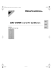
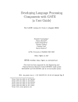
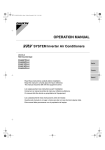
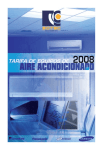
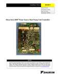
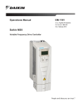
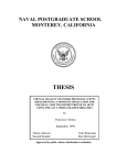
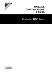
1
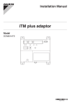
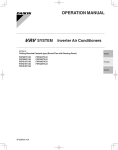
Submittal Reviewed For Reviewers Use Only: Create Markup and Save Create and Send as PDF Record Workflow Action Associate with Submittal SUBMITTAL TRANSMITTAL RECORD DATE: 12/22/2014 TSC #: 214080 The Skillman Corporation Attn: Debbie Oliver RE: CPCSC LEARNING CENTER NOTE: ONLY ONE SPECIFICATION SECTION IS TO BE SUBMITTED PER TRANSMITTAL. CONTRACTOR NAME: BID CATEGORY NAME AND NUMBER: SPECIFICATIONS SECTION NO: CIRCLE "R" MECHANICAL, INC. BID CATEGORY #10 - MECHANICAL IS THIS A RESUBMITTAL?: 23 09 00.99 YES: NO: SECTION NAME AND DESCRIPTION: MANUFACTURER/ SUPPLIER: ✔ INSTRUMENTATION AND CONTROL FOR HVAC DAIKIN NORTH AMERICA LLC TYPE OF SUBMITTAL & NUMBER OF COPIES: SHOP DRAWINGS: ✔ PRODUCT DATA: SAMPLES: ✔ COLOR SELECTIONS: CLOSE-OUT DOCUMENTS: REMARKS: SUBMITTED BY:___________________________________ _____APPROVED FOR PROCESSING - TSC Indiana Thermal Solutions 6872 Hillsdale Court Indianapolis, IN 46250 Bob Wolfram (317) 570-5400 – Phone [email protected] SUBMITTAL INSTRUMENTATION and CONTROL for HVAC SPEC. SECTION: 23 09 00.99 Project: Crown Point Community School Corporation Learning Center Location: Crown Point, Indiana Architect: Schmidt Associates, Inc. Engineer: Schmidt Associates, Inc. Contractor: Circle “R” Mechanical, Inc. Date: 12/22/2014 SUBMITTED BY: Job: Crown Point C.S.C. – Learning Center Item: VRV III Air Conditioning Spec: 23 09 00.99 Date: 12/22/2014 Reviewed by: RW Submittal Data Project: Crown Point Community School Corp Learning Center Date: December 15, 2014 Customer: Circle “R” Mechanical Engineer: Schmidt Associates Qty 2 Tag CU-1, CU-2 Description Daikin VRV Control System Spec Section 230900.99 Submitted by: Steve Miller Drawings in this submittal package describe the Indiana Thermal Solutions equipment we propose to furnish for this project and are submitted for approval to manufacture. 6872 Hillsdale Court, Indianapolis, IN 46250 Phone: (317) 570-5400 / Fax: (317) 570-5414 www.ITS-Indiana.com Produced on 12/1/2014 with Xpress Selection V6.8.6 - database Central_USA 9.7.6 Project name Reference Client name Revision Crown Point Learning Center Submittal Circle "R" Mechanical 0 1. Wiring Diagrams NOTES: 1) All wiring to be done in the field by others 2) I-Touch Manager location to be determined by others The Xpress Selection Program is property of Daikin Europe NV. Daikin Europe NV cannot be held liable for any inaccuracy, reliability of the outcome of the Xpress Selection Program. Page 1 1.1. Wiring CU-1 to centralized controller OUT F1,F2 Q1,Q2 Q1,Q2 CU-1 REYQ240TTJU REYQ144TTJU REYQ96TTJU BSB1-1 BS4Q54TVJ IN F1,F2 L1, L2, L3 55A 3ph OUT F1,F2 L1, L2 0.4A 1ph IN F1,F2 L1, L2, L3 38A 3ph F1,F2 IN F1,F2 F1,F2 IN F1,F2 F1,F2 IN F1,F2 BSB1-2 BS4Q54TVJ OUT F1,F2 L1, L2 F1,F2 F1,F2 IN F1,F2 F1,F2 IN F1,F2 F1,F2 IN F1,F2 OUT F1,F2 L1, L2 F1,F2 IN F1,F2 IN F1,F2 OUT F1,F2 OUT F1,F2 BSB1-5 BSQ36TVJ L1, L2 F1,F2 F1,F2 F1,F2 0.1A 1ph IN F1,F2 L1, L2 VRV1-1C FXMQ36PAVJU VRV1-1D FXMQ30PAVJU L1, L2 P1,P2 L1, L2 P1,P2 L1, L2 P1,P2 L1, L2 BRC1E72 2.8A 1ph BRC1E72 2.9A 1ph BRC1E72 2.9A 1ph BRC1E72 2.8A 1ph VRV1-2A FXZQ07MVJU9 VRV1-2B FXMQ18PAVJU VRV1-2C FXMQ24PAVJU VRV1-2D FXMQ12PAVJU P1,P2 L1, L2 P1,P2 L1, L2 P1,P2 L1, L2 P1,P2 L1, L2 BRC1E72 0.8A 1ph BRC1E72 1.5A 1ph BRC1E72 1.8A 1ph BRC1E72 0.6A 1ph 0.4A 1ph IN F1,F2 BSB1-4 BSQ36TVJ VRV1-1B FXMQ36PAVJU P1,P2 0.4A 1ph IN F1,F2 BSB1-3 BS4Q54TVJ VRV1-1A FXMQ30PAVJU F1,F2 0.1A 1ph IN F1,F2 F1,F2 VRV1-3A FXMQ12PAVJU VRV1-3B FXMQ12PAVJU VRV1-3C FXZQ07MVJU9 VRV1-4 FXMQ12PAVJU VRV1-5 FXMQ12PAVJU P1,P2 L1, L2 P1,P2 L1, L2 P1,P2 L1, L2 P1,P2 L1, L2 P1,P2 L1, L2 BRC1E72 0.6A 1ph BRC1E72 0.6A 1ph BRC1E72 0.8A 1ph BRC1E72 0.6A 1ph BRC1E72 0.6A 1ph The Xpress Selection Program is property of Daikin Europe NV. Daikin Europe NV cannot be held liable for any inaccuracy, reliability of the outcome of the Xpress Selection Program. Page 2 1.2. Wiring CU-2 to centralized controller OUT F1,F2 Q1,Q2 Q1,Q2 CU-2 REYQ240TTJU REYQ144TTJU REYQ96TTJU IN F1,F2 OUT F1,F2 L1, L2, L3 55A 3ph L1, L2, L3 38A 3ph BSB2-1 BSQ36TVJ BSB2-2 BS4Q54TVJ OUT F1,F2 L1, L2 0.1A 1ph IN F1,F2 L1, L2 F1,F2 OUT F1,F2 OUT F1,F2 OUT F1,F2 OUT F1,F2 OUT F1,F2 BSB2-3 BSQ36TVJ IN F1,F2 F1,F2 IN F1,F2 F1,F2 BSB2-4 BSQ36TVJ BSB2-5 BSQ36TVJ BSB2-6 BSQ36TVJ BSB2-7 BSQ36TVJ BSB2-9 BSQ36TVJ BSB2-10 BS4Q54TVJ OUT F1,F2 F1,F2 0.1A 1ph IN F1,F2 L1, L2 F1,F2 0.1A 1ph IN F1,F2 L1, L2 F1,F2 0.1A 1ph IN F1,F2 L1, L2 F1,F2 0.1A 1ph IN F1,F2 L1, L2 F1,F2 0.1A 1ph IN F1,F2 L1, L2 F1,F2 0.1A 1ph IN F1,F2 L1, L2 F1,F2 BRC1E72 0.6A 1ph F1,F2 IN F1,F2 F1,F2 IN F1,F2 F1,F2 L1, L2 VRV2-2A FXAQ09PVJU VRV2-2B FXMQ18PAVJU VRV2-2C FXMQ36PAVJU VRV2-3 FXMQ09PAVJU VRV2-4 FXMQ12PAVJU VRV2-5 FXMQ36PAVJU VRV2-6 FXMQ36PAVJU VRV2-7 FXMQ09PAVJU VRV2-9 FXMQ18PAVJU P1,P2 L1, L2 P1,P2 L1, L2 P1,P2 L1, L2 P1,P2 BRC1E72 0.3A 1ph BRC1E72 1.5A 1ph BRC1E72 2.9A 1ph BRC1E72 L1, L2 0.6A 1ph L1, L2 0.6A 1ph P1,P2 L1, L2 P1,P2 L1, L2 P1,P2 L1, L2 P1,P2 L1, L2 BRC1E72 2.9A 1ph BRC1E72 2.9A 1ph BRC1E72 0.6A 1ph BRC1E72 1.5A 1ph 0.4A 1ph IN F1,F2 BSB2-8 BS4Q54TVJ OUT F1,F2 L1, L2 P1,P2 L1, L2 0.4A 1ph IN F1,F2 OUT F1,F2 VRV2-1 FXMQ07PAVJU VRV2-10A FXMQ09PAVJU VRV2-10B FXMQ09PAVJU VRV2-10C FXAQ12PVJU P1,P2 L1, L2 P1,P2 L1, L2 P1,P2 L1, L2 BRC1E72 0.6A 1ph BRC1E72 0.6A 1ph BRC1E72 0.4A 1ph 0.4A 1ph IN F1,F2 F1,F2 IN F1,F2 F1,F2 VRV2-8A FXMQ09PAVJU VRV2-8B FXFQ30TVJU P1,P2 L1, L2 P1,P2 L1, L2 BRC1E72 0.6A 1ph BRC1E72 1.3A 1ph The Xpress Selection Program is property of Daikin Europe NV. Daikin Europe NV cannot be held liable for any inaccuracy, reliability of the outcome of the Xpress Selection Program. Page 3 2. Centralized Controllers 2.1. Concept Global Controller Models i-Touch Manager # controllers 1 Control Groups Control group 1 CU-2 (15) # outdoors 2 CU-1 (13) # indoors 28 MAU-1 MAU-2 2.2. Control group 1 CU-2 (15) REYQ240TTJU CU-1 (13) REYQ240TTJU OUT F1,F2 i-Touch Manager DCM601A71 MAU-1 MAU-2 The Xpress Selection Program is property of Daikin Europe NV. Daikin Europe NV cannot be held liable for any inaccuracy, reliability of the outcome of the Xpress Selection Program. Page 4 2.3. Dimensional Drawings i-Touch Manager DCM601A71 The Xpress Selection Program is property of Daikin Europe NV. Daikin Europe NV cannot be held liable for any inaccuracy, reliability of the outcome of the Xpress Selection Program. Page 5 Submittal Data Sheet Intelligent Touch Manager Project Name: Location: Engineer: Submitted to: Submitted by: Reference: Crown Point Learning Center Approval: Date: Construction: Unit #: Drawing #: For use with the following VRV Models: FXAQ, FXDQ, FXFQ, FXHQ, FXLQ, FXMQ, FXMQ_MF, FXNQ, FXOQ, FXSQ, FXTQ, FXZQ For use with the following Daikin SkyAir Models: FAQ, FCQ, FHQ, FTQ Capacity: Model No. Maximum Indoor Unit Groups: Max Indoor Units: Max Outdoor Units: *Systems Total: Operating Details: Power Supply (Externally supplied): Power Consumption: Operating Temp Range: Operating Humidity Range: Dimensions (WxHxD): Weight (Mass): Certifications: Communication: DIII‐NET Systems: RJ‐45 (Ethernet) 100Base‐TX or 10Base‐T USB Port USB2.0 (2GB to 32GB) RS485 (19 ‐ 22 AWG) Input Terminals: Digital Input forced shutdown of all indoor unit systems Digital Input and/or Pulse Input Terminals: intelligent Touch Manager DCM601A71 64 iTM Plus Adapter (option) DCM601A72 64 128 128 10 10 512 Indoor Unit Groups (1024 Indoor Units) 24 VAC, 60 Hz 24 VAC, 60 Hz 23 Watts 32‐104oF 85% or less (w/o condensation) 23 Watts 14 ‐ 122oF 85% or less (w/o condensation) 11.42 x 9.57 x 1.97 in. 6.30 x 5.87 x 2.41 in. 5.3 lbs. (2.4 kg) 1.1 lbs. (0.5 kg) FCC Part 15 Class B 1 1 2 N/A 1 N/A 1 1 1 N/A 3 x 10 mA @ 16 VDC/ 3 x 1 pulse at 1 or 10 kWh at 100 ms interval 4 x 10 mA @ 16 VDC/ 4 x 1 pulse at 1 or 10 kWh at 100 ms interval Configuration and engineering for each project is necessary Standard Features: Web/Email Software One year warranty Software Options: Power Proportional Distribution (PPD) Software (DCM002A71) Energy Navigator Software (DCM008A71) Hardware Options: iTM DIII‐NET Plus Adapter(DCM601A72) for expanding indoor unit groups up to 512 groups (1024 indoor units) WAGO I/O unit for controlling/ monitoring of external equipment via Di, Do, or Ai Digital Input (DEC101A51‐US2) for monitoring external equipment Digital Input/Output (DEC102A51‐US2) for controlling / monitoring of external equipment iTM Integrator (DCM601A73) for controlling/monitoring up to 5 iTMs The Power Proportional Distribution (PPD) feature supplies the user with a reasonably calculated apportionment of the total power consumption by the Daikin air‐conditioning system to individual units on the system. Because input to the PPD includes measured pulses in the refrigerant system and because the air‐conditioning system includes a number of variables, to include operating temperatures and pressures, piping lengths, heat exchange rates and others, no meter‐type apportionment of individual user’s consumption can be made. However, the PPD feature provides an apportionment methodology that uses highly advanced technology as applied to the many variables in the air‐conditioning system. *Note: See Management Size on page two for System Total explanation Daikin AC (Americas), Inc., 1645 Wallace Drive, Suite 110, Carrollton, TX 75006 Daikin AC Controls Engineering Department Generated Submittal Data www.daikinac.com (Daikin’s products are subject to continuous improvements. Daikin reserves the right to modify product design, specifications and information in this data sheet without notice and without incurring any obligations) Submittal Data Sheet Intelligent Touch Manager Project Name: Location: Engineer: Submitted to: Submitted by: Reference: Crown Point Learning Center Approval: Date: Construction: Unit #: Drawing #: Features / Benefits: Intelligent Touch Manager (iTM) DCM601A71 Management size ‐ up to 512 indoor unit groups (1024 indoor units) The iTM can manage one (1) DIII‐Net system which can have up to 64 indoor unit groups (128 indoor units). The iTM can manage up to eight (8) DIII‐Net systems with the addition of the iTM Plus Adapter which can manage one (1) DIII‐Net system each. This means up to seven (7) iTM adapters can be daisy chained to the iTM. Web Accessibility Web and Alert Email function standard with iTM Web browser shows the same screen as iTM touch screen All iTM configuration/setup can be done through Web Option or touch screen Visual Navigation Screen Floor plan layout view is available Easy installation Wall mount and flush mount installation Automatic indoor unit registration and indoor unit model detection iTM DIII‐NET Plus Adapter DCM601A72 24 VAC 60 Hz Easy Engineering iTM can be configured off site via Pre‐setting Tool All data can be uploaded and downloaded by USB flash drive History All operations, automatic controls and status changes are stored in history (up to 1,000,000 items) D‐Net compatible Energy management (Optional) Visualization of energy consumption data Pinpoint areas where energy is wasted Power Proportional Distribution (PPD) (Optional) Tenant billing Building facilities management Building facilities are connected by using WAGO I/O system (optional) I/O configuration for Digital Input, Digital Output, and Analog Input The iTM is equipped with 3 digital/pulse inputs and the iTM Plus Adapter comes equipped with 4 digital/pulse inputs Specifications of Communication Cabling (DIII‐NET) Type Size Total Length 2‐conductor, stranded, non‐shielded copper cable / PVC of vinyl jacket AWG 18‐2 Maximum wiring distance between units 3,280 ft. Total wire length 6,550 ft. Daikin AC (Americas), Inc., 1645 Wallace Drive, Suite 110, Carrollton, TX 75006 Daikin AC Controls Engineering Department Generated Submittal Data www.daikinac.com (Daikin’s products are subject to continuous improvements. Daikin reserves the right to modify product design, specifications and information in this data sheet without notice and without incurring any obligations) Submittal Data Sheet BRC1E72 - New Navigation Controller Project Name: Crown Point Learning Center Location: Engineer: Submitted to: Submitted by: Reference: Approval: Date: Construction: Unit #: Drawing #: For use with the following VRV indoor unit models: FXAQ, FXDQ, FXFQ, FXHQ, FXLQ, FXMQ, FXMQ_MF, FXNQ, FXSQ, FXTQ, FXZQ For use with the following Daikin SkyAir indoor unit models: FAQ, FBQ, FCQ, FHQ, FTQ Model Description Maximum Indoor Units Communication Wire Total Wiring Length Communication Protocol Power BRC1E72 New Navigation Remote Controller 16 18AWG‐2, No polarity Stranded, Non‐shielded 1,640 ft (500 m) Daikin Proprietary P1P2 protocol 16VDC supplied by Indoor unit (1.58VA maximum) Comfort Setpoint Range 60 to 90 oF (16 to 32 oC) Setback Setpoint Range 40 to 95 oF (5 to 35oC) Operating Temp Range 14 to 122oF (‐10 to 50oC) Operating Humidity Range Dimensions (WxHxD) Weight (Mass) 75% or less (w/o condensation) 4.72x4.72x0.75 inch (120x120x19 mm) 0.42 lb (0.19 kg) Features / Benefits: Up to 16 indoor units are controllable in one group Can be combined with a secondary controller for dual operation Backlit LCD display in English, French, or Spanish Temperature sensor with configurable offset Display of Temperature and Setpoint in 1°F / °C increments Three display modes Detailed, Standard and Simple Dual setpoints (individual cooling and heating setpoints) with minimum setpoint differential or Single setpoint (occupied period) Setpoint range limits for Cooling and Heating Independent cool/heat setback setpoints (unoccupied period) Auto changeover mode can automatically change to cool/heat mode at setpoint +/‐1° F (can be configured from 1 to 4° F using field settings) with a guard timer for 15, 30, 60 or 90 min. Surely change at another +/‐1° F (can be configured from 1 to 4° F using field settings) ignoring the guard timer. Built in 7, 5+2, 5+1+1, and 1 (Everyday) schedule with up to 5 actions per day with independent cool/heat or setback setpoints Automatic adjustment for Daylight Savings Time (DST) 48 hour clock/calendar backup (in case of power failure) Constantly monitors the system for malfunctions with immediate display of fault location and condition Prohibit buttons on remote controller Limit selectable operation modes Display can be configured not to show setpoint when unit is Off. Display Off, instead of mode when unit is off. Fan speed display removable. Backwards compatible Daikin AC (Americas), Inc., 1645 Wallace Drive, Suite 110, Carrollton, TX 75006 Daikin AC Controls Engineering Department Generated Submittal Data www.daikinac.com (Daikin’s products are subject to continuous improvements. Daikin reserves the right to modify product design, specifications and information in this data sheet without notice and without incurring any obligations) Submittal Data Sheet BRC1E72 - New Navigation Controller Project Name: Location: Engineer: Submitted to: Submitted by: Reference: Crown Point Learning Center Approval: Date: Construction: Unit #: Drawing #: Face Decal Options: Face decal options to hide unnecessary buttons o Hidden buttons can be used/accessed by service personnel without removing the face decal due to its flexibility Daikin AC (Americas), Inc., 1645 Wallace Drive, Suite 110, Carrollton, TX 75006 Daikin AC Controls Engineering Department Generated Submittal Data www.daikinac.com (Daikin’s products are subject to continuous improvements. Daikin reserves the right to modify product design, specifications and information in this data sheet without notice and without incurring any obligations) Note: Factory installed in: MAU-1 & 2 Installation and Maintenance Manual IM 919-3 Group: Applied Air Systems Part Number: IM 919 Date: October 2014 MicroTech® III Controller for Commercial Rooftop Systems, Applied Rooftop Systems and Self-Contained Air Conditioners Models: DPS, MPS, RAH, RCS, RDS, RDT, RFS, RPE, SWP and SWT Introduction Main Control Board (MCB) Figure 4: Dip Switch Settings Figure 1: Main Control Board Analog Inputs Universal I/O Digital Inputs Internal Modbus Remote Keypad/ Display Power Supply Digital Inputs Digital Outputs Expansion Board A Switch #5 in the up position (all others down) Expansion Board B Switch #4 in the up position (all others down) Expansion Board C Switch #4 and #5 in the up position (all others down) Expansion Board D Switch #3 in the up position (all others down) Expansion Board E Switch #3 and #5 in the up position (all others down) Figure 2: Expansion Boards A, B, C, D, E Universal I/O Dipswitch #6 Switch #6 must be in the up position on the last expansion board in the string regardless whether it is A, B, C, D, or E. Table 2: MCB I/O Connection Labeling Digital Output Dip Switches Digital Input Figure 3: Expansion Board Side Views MCB I/O Connection Label T1 24 VOLT POWER SUPPLY T2 DIGITAL OUTPUT 1, T3 DIGITAL OUTPUT 2, 3, 4 T4 DIGITAL OUTPUT 5, 6, 7, 8 T5 DIGITAL OUTPUT 9, 10 T6 DIGITAL INPUT 5, 6 T7 ANALOG INPUT 1, 2, 3 T8 UNIVERSAL I/O 1, 2, 3, 4 T9 UNIVERSAL I/O 5, 6, 7, 8 T10 DIGITAL INPUT 1, 2 T11 DIGITAL INPUT 3, 4 T12 MODBUS/VFD T13 PROCESS BUS/FUTURE IM 919-3 • MICROTECH III CONTROLLER4 www.DaikinApplied.com Keypad/Display The keypad/display consists of a 5-line by 22 character display, three keys and a “push and roll” navigation wheel. There is an Alarm Button, Menu (Home) Button, and a Back Button. The wheel is used to navigate between lines on a screen (page) and to increase and decrease changeable values when editing. Pushing the wheel acts as an Enter Button. Keypad/Display Figure 5: Keypad/Display The first line on each page includes the page title and the line number to which the cursor is currently “pointing”. The line numbers are X/Y to indicate line number X of a total of Y lines for that page. The left most position of the title line includes an “up” arrow to indicate there are pages “above” the currently displayed items, a “down” arrow to indicate there are pages “below” the currently displayed items or an “up/down” arrow to indicate there are pages “above and below” the currently displayed page. Each line on a page can contain status only information or include changeable data fields. When a line contains status only information and the cursor is on that line all but the value field of that line is highlighted meaning the text is white with a black box around it. When the line contains a changeable value and the cursor is at that line, the entire line is highlighted. Each line on a page may also be defined as a “jump” line, meaning pushing the navigation wheel will cause a “jump” to a new page. An arrow is displayed to the far right of the line to indicate it is a “jump” line and the entire line is highlighted when the cursor is on that line. The Main Menu allows the user to enter a password, access the Quick Menu pages, view the current unit state, access the Alarm List Menu as well as access to information about the unit. The Quick Menu provides access to status information indicating the current operating condition of the unit. The View/Set Unit Menus include basic menus and items required to setup the unit for general operation. These include such things as control mode, occupancy mode, and heating and cooling setpoints. The Commission Unit Menus include more advanced items for “tuning” unit operation such as PI loop parameters and time delays. The Manual Control Menu allows service personnel to test unit specific operation manually. The Unit Configuration Menu allows the user to access to the unit specific configuration information. These generally do not needing changing or accessing unless there is a fundamental change to, or a problem with, the unit operation. The Alarm Lists Menu includes active alarm and alarm log information. The keypad/display Information is organized into Menu groups; Main Menu, Quick Menu, View/Set Unit Menu, Commission Unit Menu, Manual Control Menu, Service Menu, Unit Configuration Menu and Alarm list Menus. NOTE: Only menus and items that are applicable to the specific unit configuration are displayed. www.DaikinApplied.com 5 IM 919-3 • MICROTECH III CONTROLLER Installation Manual DPS/MPS/RAH/RPS/SWP Space Sensor © 2013 Daikin Applied Note: Field installed for: IM 1199 MAU-1 & 2 Group: Applied Air Part Number: IM 1199 Date: May 2013 Installation Front Panel Figure 3: Front Panel Display The display is standard for all sensors. The functional keys on the display include the setpoint adjustment buttons and the tenant override button, as well as a numerical display to view changes. Setpoint Buttons : When pressed, the setpoint will display for three to four seconds. When pressed again, the setpoint will change in one degree increments. It will only change within the setpoint range that was ordered. Tenant Override Button : When the override button is pressed for 3-5 seconds the tenant override function will be initiated per the MicroTech III controller. The amount of time that the unit will come out of the unoccupied mode and operate in the tenant override mode is adjustable at the unit controller. Numerical Display The default display shows current temperature. When the up/down buttons are pushed, then the display will show and adjust the current setpoint and hold the display for 3 to 4 seconds. The unit can also be set up to display setpoint only or for setpoint lockout. 4 IM 1199 Specifications and Parts Specifications and Parts Sensor Specs Parts Power: 15 to 28 VAC 924 VAC nominal) Part Number: 910143408 Power Consumption: .17 VA maximum AC Wiring: See Terminal section (page 3) Display: LCD - 3.5 digits @ 0.6 inch H Temperature display units - 0.1° (F/C) increments Setpoints in 0.5° steps Button Options: Setpoint Up/Down buttons Tenant Override button Environmantal Ambient: Temperature - 32 to 122°F (0 to 50°C) Humidity - 0 to 95% RH non-condensing Material: ABS plastic, UL94V-0 IM 1199 5 Note: Factory installed in: MAU-1 & 2 Operation and Maintenance Manual IM 1133-1 Group: Controls Part Number: IM 1133 Date: January 22, 2014 Supersedes: IM 1133 DIII-NET Communication Gateway For Daikin Air Handling Units integrated with a Daikin VRV System Applied Rooftop Model: DPS IM 1133-C Component Data Major components of the DIII-NET Communication Gateway are labeled in . Figure 2, DIII-NET Communication Gateway Installed 24VAC DIII Communication Port LED’s H1P through H7P. DS1 Part Number DS2 Modbus Communication Port Light Emitting Diodes (LEDs) The LED’s on the DIII-NET Communication Gateway are used to indicate either the DIII-NET Communication Gateway is working correctly or there is a fault. A description of what each of the LEDs being energized or de-energized means is listed in Table 1. Table 1, LED’s LED Function OFF ON H1P DIII-NET Sending Not Transmitting Transmitting H2P DIII-NET Receiving Not Receiving Receiving H3P Modbus Sending Not Transmitting Transmitting H4P Modbus Receiving Not Receiving Receiving H5P MicroTech III Fault Indication No Faults Fault Alarm H6P MicroTech III Problem Indication No Problems Problem Alarm H7P MicroTech III Warning Indication No Warnings Warning Alarm HAP Micro Processor Operation DIII-NET COMMUNICATION GATEWAY 800ms Flashing Period Indicates Operation 7 www.DaikinApplied.com IM 1133-C Installation The DIII-NET Communication Gateway will be factory installed. If it is necessary to replace this board, see section Replacing DIII-NET Communication Gateway. If a new board is being installed on an existing unit, see section Installing a New DIII_NET Communication Gateway. Wiring ! CAUTION Electrostatic discharge hazard. Can cause equipment damage. This equipment contains sensitive electronic components that may be damaged by electrostatic discharge from your hands. Before you handle a communications module, you need to touch a grounded object, such as the metal enclosure, in order to discharge the electrostatic potential in your body. Installing a New DIII-NET Communication Gateway ! WARNING Hazardous voltage. Can cause severe injury or death. Disconnect electric power before servicing equipment. More than one disconnect may be required to de-energize the unit. 1. Remove power from the MicroTech III Applied Air Handling Unit Controller. 2. Remove power from the Daikin Air Handling Unit. 3. Install mounting bracket on the side wall of the control cabinet with 4 rivets/screws, see Figure 3. 4. Mount DIII-NET Communication Gateway to the mounting bracket with 4 standard circuit board standoffs. Verify the board is securely attached to the mounting bracket. See Figures 3 and 4. Figure 3, Mounting bracket installation DIII-NET COMMUNICATION GATEWAY 8 www.DaikinApplied.com IM 1133-C 5. Install 120/24 VAC transformer in the control cabinet. The DIII-NET Communication Gateway must have its own, power supply. 6. Wire 120VAC power to the transformer using open terminals from the T1 transformer inside the unit control cabinet. The secondary of this transformer must remain ungrounded. Figure 4, DIII-NET Communication Gateway mounted in unit 7. Connect the 24VAC power from the transformer to X6A on the DIII-NET Communication Gateway using the provided wire harness. See Figure 5. 8. If there are fewer than 2 pairs of modbus wires going to the MCB, skip to step 11. If there are 2 pairs continue with step 9. 9. Remove 1 pair of modbus wires from the MCB. (A positive and its associated negative.) Note: the 2 wires removed must be a pair connecting the same two devices. See Figure 6. 10. Attach the disconnected wires from the MCB to the Modbus Communication Port (X2M) on the DIII-NET Communication Gateway. (+ to terminal A, and – to terminal B.) See Figure 5. BLK 260A-2 B-/1 WHT 260A-3 A+/1 To Modbus port on MCB DRN 260A-4 COM/1 Figure 5, DIII-NET Communication Gateway Schematics BA+ X6A -1 DKND3 251A-1I D3.24V/2.51 X6A -2 263A-4I X6A -3 To other components communicating Modbus ON OFF 24 V Power Supply 1234 1234 DS1 DS2 X7-1 X7-2 To Daikin Intelligent Touch Controller or iTouch Manager DIII-NET COMMUNICATION GATEWAY 268A-1 TB2 267A-1 TB2 9 128 129 www.DaikinApplied.com IM 1133-C Figure 6, Incorporating DIII-NET board into an existing Modbus Daisy Chain 11. Connect a pair of wires from the MCB to the Modbus Communication Port (X2M) on the DIII-NET Communication Gateway. See Figure 5. (There should be 2 pairs of modbus wires connected to the MCB at this point, unless there were none to begin with, see Figure 6.) 12. The DIII-NET Communications Gateway is treated like any other outdoor unit on the DIII-NET communications trunk. Connect DIII-NET communication wires from the outdoor unit trunk to the DIII-NET communications port (X7A), using the provided wire harness. See Figure 7. Polarity does not matter. For more information on DIII-Net communications wiring refer to Manual DCS601C71 Figure 7, DIII-NET Wiring Schematic DIII-NET COMMUNICATION GATEWAY 10 www.DaikinApplied.com IM 1133-C 13. Position the binary DIP switches on the DIII-NET Communication Gateway to “0110 1010” as configured in Figure 8. 14. Power up the Daikin Applied Air Handling Unit, MicroTech III Unit Controller and DIII-NET Communication Gateway. 15. Configure MicroTech III and Daikin VRV unit controllers as instructed in the Integration section. For information on the iTouch Manager, refer to user’s manual EM11A017. Figure 8, DIP Switch Configuration In Figure 8, flipping the binary switches up is on, and flipping them down is off. Switches should be configured to 0110 1010 as shown. Replacing an Existing DIII-NET Communication Gateway To replace a DIII-NET Communication Gateway: ! WARNING Hazardous voltage. Can cause severe injury or death. Disconnect electric power before servicing equipment. More than one disconnect may be required to de-energize the unit. 1. 2. 3. 4. 5. 6. Remove power from the Daikin Applied Air Handling Unit. Disconnect all wiring to DIII-NET Communication Gateway. Remove old DIII-NET Communication Gateway from its mountings. Replace with new DIII-NET Communication Gateway in same manner as the old board. Verify the board is securely attached to the unit. See Figure 4. Reconnect all wiring. See Figure 2. Use the existing wires only if they are in good condition; do not attempt to use worn or damaged wires under any circumstances. See the “Service Information” section of this document for a list replacement parts. Confirm binary switches per instructions in step 13 of section “Installing a New DIII-NET Communication Gateway.” See Figure 8. 7. Power up the Daikin Applied Air Handling Unit. 8. Confirm address and parameters on unit controller, as per instructions in the Integration section . DIII-NET COMMUNICATION GATEWAY 11 www.DaikinApplied.com IM 1133-C Integration Once the DIII-NET Communication Gateway has been properly installed on the unit and connected to a DIII network, it is then possible to integrate the unit controller with a Daikin Intelligent Touch Controller or iTouch Manager over a DIII network. The integration process is described in the following section. Configuring the DIII-NET Communication Gateway The MicroTech III Applied Air Handling Unit Controller and optional DIII-NET Communication Gateways are designed, programmed, and configured at the factory. However, the DIII-NET Communication Gateway needs to have a unique indoor unit address compatible with the existing DIII network. This address and any other configurations can be set through the keypad on the MicroTech III Unit Controller. The unit is ready to operate with the default parameter values in the unit controller even before you change the default parameters for your particular network. Appendix B lists the menu items for the “D3 Set-Up Menu” and “D3 Status Menu.” Note: Refer to Operation Manual OM 920 for details regarding the MicroTech III Applied Air Handling Unit Controller keypad/display. Manual is available at www.DaikinApplied.com DIII-NET COMMUNICATION GATEWAY 12 www.DaikinApplied.com