1
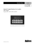
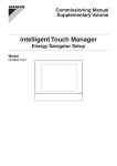
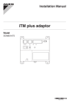
Operation and Maintenance Manual IM 1133-1 Group: Controls Part Number: IM 1133 Date: January 22, 2014 Supersedes: IM 1133 DIII-NET Communication Gateway For Daikin Air Handling Units integrated with a Daikin VRV System Applied Rooftop Model: RPS, RDT & RAH Commercial Rooftop Model: MPS Self-Contained Model: SWP & SWT IM 1133-C Contents FIGURES ...................................................................................................................................................................................3 REVISION HISTORY .....................................................................................................................................................................4 REFERENCE DOCUMENTS.............................................................................................................................................................4 LIMITED WARRANTY ...................................................................................................................................................................4 GENERAL INFORMATION ......................................................................................................................................................5 HAZARD IDENTIFICATION MESSAGES .............................................................................................................................................5 RECOGNIZE SAFETY SYMBOLS, WORDS AND LABELS..........................................................................................................................5 DESCRIPTION ............................................................................................................................................................................6 APPLICATION.............................................................................................................................................................................6 COMPONENT DATA ....................................................................................................................................................................7 Light Emitting Diodes (LEDs) .................................................................................................................................................7 INSTALLATION ......................................................................................................................................................................8 WIRING ...................................................................................................................................................................................8 Installing a New DIII-NET Communication Gateway .............................................................................................................8 Replacing an Existing DIII-NET Communication Gateway ...................................................................................................11 INTEGRATION .....................................................................................................................................................................12 CONFIGURING THE DIII-NET COMMUNICATION GATEWAY ..............................................................................................................12 DIII-NET Communication Gateway Addressing ...................................................................................................................13 Configuring the DIII Board and MicroTech III Controller .....................................................................................................14 INTELLIGENT TOUCH CONTROLLER CONFIGURATION .......................................................................................................................15 Change an Icon on the Intelligent Touch Controller: ...........................................................................................................15 Creating a New Zone and Setting the Intelligent Touch Controller Dead Band ..................................................................17 INTELLIGENT TOUCH CONTROLLER OPERATION ..............................................................................................................................20 MicroTech III Unit Operation ...............................................................................................................................................20 Adjusting Discharge Air Setpoint .........................................................................................................................................21 Adjusting Fan Speed ............................................................................................................................................................22 ITOUCH MANAGER CONFIGURATION ...........................................................................................................................................24 Auto Register a Unit to the iTouch Manager ......................................................................................................................24 Manually Add a Unit to the iTouch Manager ......................................................................................................................26 Changing Icon and Description on iTouch Manager ...........................................................................................................29 ITOUCH MANAGER OPERATION ..................................................................................................................................................31 Turning a Unit On and Off ...................................................................................................................................................31 Adjusting Setpoints .............................................................................................................................................................32 Changing Fan Speed ............................................................................................................................................................32 Advanced Settings ...............................................................................................................................................................33 SERVICE INFORMATION .....................................................................................................................................................36 TEST PROCEDURES ...................................................................................................................................................................36 PARTS LIST .............................................................................................................................................................................36 Communication Board ........................................................................................................................................................36 Field Install Kit .....................................................................................................................................................................36 APPENDIX A .......................................................................................................................................................................37 ALARMS .................................................................................................................................................................................37 APPENDIX B .......................................................................................................................................................................38 CONFIGURABLE PARAMETERS .....................................................................................................................................................38 DIII-NET COMMUNICATION GATEWAY 2 www.DaikinApplied.com IM 1133-C Figures Figure 1, Maverick II Rooftop Unit .................................................................................................................................................................................... 6 Figure 2, DIII-NET Communication Gateway Installed ..................................................................................................................................................... 7 Figure 3, Mounting bracket installed in unit. ..................................................................................................................................................................... 8 Figure 4, DIII-NET Communication Gateway mounted in unit .......................................................................................................................................... 9 Figure 5, DIII-NET Communication Gateway Schematics ................................................................................................................................................. 9 Figure 6, Incorporating DIII-NET board into an existing Modbus Daisy Chain ............................................................................................................... 10 Figure 7, DIII-NET Wiring Schematic.............................................................................................................................................................................. 10 Figure 8, DIP Switch Configuration ................................................................................................................................................................................. 11 Figure 9 MicroTech III Menu Structure ............................................................................................................................................................................ 13 Figure 10, Zone Screen on Intelligent Touch Controller ................................................................................................................................................... 15 Figure 11, System Setting Screen Shot, Intelligent Touch Controller ............................................................................................................................... 15 Figure 12, Zone/Group Selection Screen, Intelligent Touch Controller ............................................................................................................................ 15 Figure 13, Zone / Group Screen 16 Figure 14, Group Settings Screen 16 Figure 15, All Zones Display on Intelligent Touch Controller .......................................................................................................................................... 17 Figure 16, System Settings Screen.................................................................................................................................................................................... 17 Figure 17, System Menu for Selecting Zone/Group ......................................................................................................................................................... 17 Figure 18, System Zone Group Screen ............................................................................................................................................................................. 18 Figure 19, System Menu for Setting up New Zone ........................................................................................................................................................... 18 Figure 20, Configure Screen for Setting Setpoint Range .................................................................................................................................................. 19 Figure 21, Setpoint Range Configuration Screen ............................................................................................................................................................. 19 Figure 22, MicroTech III Air Handling Unit in Occupied Mode ...................................................................................................................................... 20 Figure 23, MicroTech III Air Handler Unit in Unoccupied Mode .................................................................................................................................... 20 Figure 24, MicroTech III Air Handler in Unoccupied Operation...................................................................................................................................... 21 Figure 25, With MicroTech III Air Handling Unit Selected ............................................................................................................................................. 21 Figure 26, Configure Screen for MicroTech III Air Handling Unit Std Version ............................................................................................................... 22 Figure 27, Configure Screen for MicroTech III Air Handling Unit US Version. .............................................................................................................. 22 Figure 28, MicroTech III Air Handling Unit Selected. ..................................................................................................................................................... 23 Figure 29, Advanced Settings Configuration Screen ........................................................................................................................................................ 23 Figure 30, iTouch Manager Home Screen ........................................................................................................................................................................ 24 Figure 31, Accessing Service Login ................................................................................................................................................................................. 24 Figure 32, Service Login Screen 25 Figure 33, Service Login Menu List – Auto Register ....................................................................................................................................................... 25 Figure 34, Auto Register Screen 25 Figure 35, Confirm Auto Register Changes...................................................................................................................................................................... 26 Figure 36, Service Login Menu List – Manually Register ................................................................................................................................................ 26 Figure 37, Add Management Point to iTouch Manager ................................................................................................................................................... 27 Figure 38, Management Point Type ................................................................................................................................................................................. 27 Figure 39, Setting Unit Address and Name ...................................................................................................................................................................... 28 Figure 40, DIII Address Drop-down Menu 27 Figure 41, Setting Unit Name 28 Figure 42, New Management Point on iTouch Manager .................................................................................................................................................. 28 Figure 43, Confirm Register Data Point ........................................................................................................................................................................... 28 Figure 44, Unit Selected for Editing ................................................................................................................................................................................. 29 Figure 45, Editing Unit Information ................................................................................................................................................................................. 29 Figure 46, Entering Detailed Information ......................................................................................................................................................................... 30 Figure 47, Icon Selection 30 Figure 48, Turning Unit On and Off ................................................................................................................................................................................. 31 Figure 49, Confirm Start/Stop Unit .................................................................................................................................................................................. 31 Figure 50, Adjusting Setpoints from the iTouch Manager ............................................................................................................................................... 32 Figure 51, Adjusting Fan Speed from the iTouch Manager .............................................................................................................................................. 33 Figure 52, Accessing Detailed Settings ............................................................................................................................................................................ 33 Figure 53, Detailed Settings Screen .................................................................................................................................................................................. 34 Figure 54, Setpoint Restrictions 34 DIII-NET COMMUNICATION GATEWAY 3 www.DaikinApplied.com IM 1133-C Revision History IM 1133 August 2011 Initial release IM 1133-RevB November 2013 Revised and expanded on adding a new DIII board to an existing unit, updated all figure numbers. Sections added on iTouch configuration and operation; includes 27 new Figures. Reference Documents Number Company Title Source OM 920 Daikin www.DaikinApplied.com IM 919 Daikin MicroTech III Applied Air Handling Unit Controller Operation and Maintenance Manual MicroTech III Applied Air Handling Unit Controller Installation Manual Intelligent Touch Controller Installation Manual intelligent Touch Manager Installation Manual intelligent Touch Manager User’s Manual Design Guide Intelligent Touch Controller www.daikinac.com intelligent Touch Manager Commissioning Manual www.daikinac.com DCS601C71 Daikin Air Conditioning Americas DCM601A71 Daikin Air Conditioning Americas EM11A017A Daikin Air Conditioning Americas ED72-423 Daikin Air Conditioning Americas EM11A022 Daikin Air Conditioning Americas www.DaikinApplied.com www.daikinac.com www.daikiac.com www.daikinac.com Limited Warranty Consult your local Daikin Representative for warranty details. Refer to Form 933-43285Y. To find your local Daikin representative, go to www.DaikinApplied.com. Notice © 2014 Daikin Applied, Minneapolis MN. All rights reserved throughout the world. Daikin reserves the right to change any information contained herein without prior notice. The user is responsible for determining whether this software is appropriate for his or her application. ® ™ The following are tradenames or registered trademarks of their respective companies: Modbus from Schneider Electric; Daikin, RoofPak, Maverick and MicroTech III from Daikin. DIII-NET COMMUNICATION GATEWAY 4 www.DaikinApplied.com IM 1133-C General Information This manual contains the information you need to install the DIII-NET Communication Gateway on a MicroTech® III Applied Air Handling Unit (AAH) Controller (i.e., RoofPak™ applied rooftop, Maverick™ II commercial rooftop or Self-Contained Unit), incorporate it into the DIII-Net network, and maintain it. Hazard Identification Messages Recognize Safety Symbols, Words and Labels The following symbols and labels are used throughout this manual to indicate immediate or potential hazards. It is the owner and installer’s responsibility to read and comply with all safety information and instructions accompanying these symbols. Failure to heed safety information increases the risk of property damage and/or product damage, serious personal injury or death. Improper installation, operation and maintenance can void the warranty. ! DANGER Dangers indicate a hazardous situation which will result in death or serious injury if not avoided. ! WARNING Warnings indicate potentially hazardous situations, which can result in property damage, severe personal injury, or death if not avoided. ! CAUTION Cautions indicate potentially hazardous situations, which can result in personal injury or equipment damage if not avoided. ! WARNING Electric shock hazard. Can cause personal injury or equipment damage. This equipment must be properly grounded. Connections and service to the MicroTech III Air Handling Unit Controller must be performed only by personnel knowledgeable in the operation of the equipment being controlled. ! CAUTION Static sensitive components. Can cause equipment damage. Discharge any static electrical charge by touching the bare metal inside the control panel before performing any service work. Never unplug cables, circuit board terminal blocks, or power plugs while power is applied to the panel. DIII-NET COMMUNICATION GATEWAY 5 www.DaikinApplied.com IM 1133-C NOTICE This equipment generates, uses and can radiate radio frequency energy and, if not installed and used in accordance with this instruction manual, may cause interference to radio communications. It has been tested and found to comply with the limits for a Class A digital device, pursuant to part 15 of the FCC rules. These limits are designed to provide reasonable protection against harmful interference when the equipment is operated in a commercial environment. Operation of this equipment in a residential area is likely to cause harmful interference in which case the user will be required to correct the interference at his or her own expense. Daikin disclaims any liability resulting from any interference or for the correction thereof. ! WARNING Electric shock hazard. Can cause personal injury or equipment damage. This equipment has exposed electrical connections inside DIII-Net Communication Gateway. Only personnel that are knowledgeable in the operation of this equipment must perform connections and service to the DIII-NET-Net Communication Gateway. Description The DIII-NET Communication Gateway allows communication between the MicroTech III unit controller and the Daikin variable air volume (VRV) DIII network via a Modbus® communication Gateway (DIII-NET Communication Gateway). Figure 1, Maverick II Rooftop Unit Application The MicroTech III controller will act as a Modbus master device communicating with the DIII-NET Communication Gateway acting as a Modbus slave device. The DIII-NET Communication Gateway will translate the Modbus point information into the DIII-NET protocol and vice-versa. DIII-NET COMMUNICATION GATEWAY 6 www.DaikinApplied.com IM 1133-C Component Data Major components of the DIII-NET Communication Gateway are labeled in . Figure 2, DIII-NET Communication Gateway Installed 24VAC DIII Communication Port LED’s H1P through H7P. DS1 Part Number DS2 Modbus Communication Port Light Emitting Diodes (LEDs) The LED’s on the DIII-NET Communication Gateway are used to indicate either the DIII-NET Communication Gateway is working correctly or there is a fault. A description of what each of the LEDs being energized or de-energized means is listed in Table 1. Table 1, LED’s LED Function OFF ON H1P DIII-NET Sending Not Transmitting Transmitting H2P DIII-NET Receiving Not Receiving Receiving H3P Modbus Sending Not Transmitting Transmitting H4P Modbus Receiving Not Receiving Receiving H5P MicroTech III Fault Indication No Faults Fault Alarm H6P MicroTech III Problem Indication No Problems Problem Alarm H7P MicroTech III Warning Indication No Warnings Warning Alarm HAP Micro Processor Operation DIII-NET COMMUNICATION GATEWAY 800ms Flashing Period Indicates Operation 7 www.DaikinApplied.com IM 1133-C Installation The DIII-NET Communication Gateway will be factory installed. If it is necessary to replace this board, see section Replacing DIII-NET Communication Gateway. If a new board is being installed on an existing unit, see section Installing a New DIII_NET Communication Gateway. Wiring ! CAUTION Electrostatic discharge hazard. Can cause equipment damage. This equipment contains sensitive electronic components that may be damaged by electrostatic discharge from your hands. Before you handle a communications module, you need to touch a grounded object, such as the metal enclosure, in order to discharge the electrostatic potential in your body. Installing a New DIII-NET Communication Gateway ! WARNING Hazardous voltage. Can cause severe injury or death. Disconnect electric power before servicing equipment. More than one disconnect may be required to de-energize the unit. 1. Remove power from the MicroTech III Applied Air Handling Unit Controller. 2. Remove power from the Daikin Air Handling Unit. 3. Install mounting bracket on the side wall of the control cabinet with 4 rivets/screws, see Figure 3. 4. Mount DIII-NET Communication Gateway to the mounting bracket with 4 standard circuit board standoffs. Verify the board is securely attached to the mounting bracket. See Figures 3 and 4. Figure 3, Mounting bracket installation DIII-NET COMMUNICATION GATEWAY 8 www.DaikinApplied.com IM 1133-C 5. Install 120/24 VAC transformer in the control cabinet. The DIII-NET Communication Gateway must have its own, power supply. 6. Wire 120VAC power to the transformer using open terminals from the T1 transformer inside the unit control cabinet. The secondary of this transformer must remain ungrounded. Figure 4, DIII-NET Communication Gateway mounted in unit 7. Connect the 24VAC power from the transformer to X6A on the DIII-NET Communication Gateway using the provided wire harness. See Figure 5. 8. If there are fewer than 2 pairs of modbus wires going to the MCB, skip to step 11. If there are 2 pairs continue with step 9. 9. Remove 1 pair of modbus wires from the MCB. (A positive and its associated negative.) Note: the 2 wires removed must be a pair connecting the same two devices. See Figure 6. 10. Attach the disconnected wires from the MCB to the Modbus Communication Port (X2M) on the DIII-NET Communication Gateway. (+ to terminal A, and – to terminal B.) See Figure 5. BLK 260A-2 B-/1 WHT 260A-3 A+/1 To Modbus port on MCB DRN 260A-4 COM/1 Figure 5, DIII-NET Communication Gateway Schematics BA+ X6A -1 DKND3 251A-1I D3.24V/2.51 X6A -2 263A-4I X6A -3 To other components communicating Modbus 24 V Power Supply 1234 1234 DS1 DS2 ON OFF X7-1 X7-2 To Daikin Intelligent Touch Controller or iTouch Manager DIII-NET COMMUNICATION GATEWAY 268A-1 TB2 267A-1 TB2 9 128 129 www.DaikinApplied.com IM 1133-C Figure 6, Incorporating DIII-NET board into an existing Modbus Daisy Chain 11. Connect a pair of wires from the MCB to the Modbus Communication Port (X2M) on the DIII-NET Communication Gateway. See Figure 5. (There should be 2 pairs of modbus wires connected to the MCB at this point, unless there were none to begin with, see Figure 6.) 12. The DIII-NET Communications Gateway is treated like any other outdoor unit on the DIII-NET communications trunk. Connect DIII-NET communication wires from the outdoor unit trunk to the DIII-NET communications port (X7A), using the provided wire harness. See Figure 7. Polarity does not matter. For more information on DIII-Net communications wiring refer to Manual DCS601C71 Figure 7, DIII-NET Wiring Schematic DIII-NET COMMUNICATION GATEWAY 10 www.DaikinApplied.com IM 1133-C 13. Position the binary DIP switches on the DIII-NET Communication Gateway to “0110 1010” as configured in Figure 8. 14. Power up the Daikin Applied Air Handling Unit, MicroTech III Unit Controller and DIII-NET Communication Gateway. 15. Configure MicroTech III and Daikin VRV unit controllers as instructed in the Integration section. For information on the iTouch Manager, refer to user’s manual EM11A017. Figure 8, DIP Switch Configuration In Figure 8, flipping the binary switches up is on, and flipping them down is off. Switches should be configured to 0110 1010 as shown. Replacing an Existing DIII-NET Communication Gateway To replace a DIII-NET Communication Gateway: ! WARNING Hazardous voltage. Can cause severe injury or death. Disconnect electric power before servicing equipment. More than one disconnect may be required to de-energize the unit. 1. 2. 3. 4. 5. 6. Remove power from the Daikin Applied Air Handling Unit. Disconnect all wiring to DIII-NET Communication Gateway. Remove old DIII-NET Communication Gateway from its mountings. Replace with new DIII-NET Communication Gateway in same manner as the old board. Verify the board is securely attached to the unit. See Figure 4. Reconnect all wiring. See Figure 2. Use the existing wires only if they are in good condition; do not attempt to use worn or damaged wires under any circumstances. See the “Service Information” section of this document for a list replacement parts. Confirm binary switches per instructions in step 13 of section “Installing a New DIII-NET Communication Gateway.” See Figure 8. 7. Power up the Daikin Applied Air Handling Unit. 8. Confirm address and parameters on unit controller, as per instructions in the Integration section . DIII-NET COMMUNICATION GATEWAY 11 www.DaikinApplied.com IM 1133-C Integration Once the DIII-NET Communication Gateway has been properly installed on the unit and connected to a DIII network, it is then possible to integrate the unit controller with a Daikin Intelligent Touch Controller or iTouch Manager over a DIII network. The integration process is described in the following section. Configuring the DIII-NET Communication Gateway The MicroTech III Applied Air Handling Unit Controller and optional DIII-NET Communication Gateways are designed, programmed, and configured at the factory. However, the DIII-NET Communication Gateway needs to have a unique indoor unit address compatible with the existing DIII network. This address and any other configurations can be set through the keypad on the MicroTech III Unit Controller. The unit is ready to operate with the default parameter values in the unit controller even before you change the default parameters for your particular network. Appendix B lists the menu items for the “D3 Set-Up Menu” and “D3 Status Menu.” Note: Refer to Operation Manual OM 920 for details regarding the MicroTech III Applied Air Handling Unit Controller keypad/display. Manual is available at www.DaikinApplied.com DIII-NET COMMUNICATION GATEWAY 12 www.DaikinApplied.com IM 1133-C DIII-NET Communication Gateway Addressing Before a unit can be viewed and controlled through a DIII network, the DIII-NET Communication Gateway must be assigned a DIII address. Configuring the DIII board is done through the MicroTech III unit controller. The following diagram in Figure 9 details the menu structure of the MicroTech III Applied Air Handling Unit Controller related to the DIII-NET Communication Gateway. Figure 9 MicroTech III Menu Structure Enter Password Enter PW **** Commission Unit Main Menu Unit Set-Up Enter Password Timer Settings Quick Menu SAF Set-Up View/Set Unit RF/EF Set-Up Unit State= ________ Htg/Clg ChgOvr Set-Up Unit Status = _______ Cooling Set-Up Ctrl Mode= Off Econo Set-Up Occ Mode= Auto Min OA Set-Up Commission Unit Heating Set-Up Manual Control 1 Service Menus Dehum Set-Up Energy Rec Set-Up Unit Maintenance Head Pressure Set-Up BMS Communications Evap Cond Set-Up Alarm Lists Alarm Configuration About This AHU Service Menus D3 Satus Menu Timer Settings D3 Com Sts= (Ok, Error) Operating Hours D3 Addr Err= (Ok, Error) Active Alarms D3 On/Off= (On, Off) Alarm Log D3 Mode= (Auto, Cooling, Heating, Fan) Alarm Configuration D3 Clg Spt= (0-100°F) D3 Status Menu D3 Htg Spt= (0-100°F) D3 Set Up D3 Set Up ItouchVer= (std/US) Unit D3 Addr= parameter to unit set up menu Set D3 Addr= Set D3 Addr= No Set OA Unit= (No/Yes) Yes OA Unit Num= (0, 0-10) OA Unit Amps= (0,0-9999 amps) OA Unit Addr= (0, 0-64) D3 SAF Spd= (0-100%) Rst All OA= (No/Yes) Max Load= (20%, 0-100%) D3 Min Load= (0-100%) D3 Max Load= (0-100%) Min Load= (50%, 0-100%) D3 Eco Ena= (Disabled, Enabled) HiCapReset= Yes/No D3 SWVersion= ______ DATHiDiff= (5°F, 0-20°F) OAAdd1-16= (1111111111111111) DATLoDiff= (10°F, 0-20°F) OAAdd17-32= (1111111111111111) Eco Method= OAAdd33-48= (1111111111111111) OAEnth Max= [57KJ/Kg (24.50 BTU/lb),1-150 KJ/Kg (0-64.49 BTU/lb)] OAAdd49-64= (1111111111111111) OAHum Max= [10.7 g/Kg (0.107 lb/lb), 0-30 g/Kg (0-0.300 lb/lb)] Eco Method None(0) Enth(1) OATHum(2) EnOATHum(3) D3fansteps= (NA, 1-5) Low Speed= (0-100%) Med Speed= (0-100%) Hi Speed= (0-100%) To set the DIII-NET Communication Gateway’s address through the MicroTech III Unit Controller: 1. 2. 3. 4. 5. 6. Navigate to the Enter Password screen if you have not already entered a password. If you have entered a password, skip to step 3. Enter Password: 6363. Navigate to “D3 Set Up Menu” under Commission Unit In the D3 Set-Up menu, select Set “Unit D3 addr” Set the unit’s DIII address. Each unit on the DIII network must have a unique address. This is the parameter used by the intelligent Touch Controller/Manager to identify a particular unit. Change “Set D3 addr” to “Yes” this should automatically switch back to “No” after a few seconds. This menu item saves the address from Step 5. Changes to the D3 address will not be saved if the address is not set. DIII-NET COMMUNICATION GATEWAY 13 www.DaikinApplied.com IM 1133-C Configuring the DIII Board and MicroTech III Controller 1. 2. 3. 4. 5. 6. 7. 8. 9. Navigate to the Enter Password screen if you have not already entered a password. If you have entered a password, skip to step 3. Enter Password: 6363. Navigate to Commission Unit\D3 Set Up menu In the D3 Set-Up menu, set “ITouch Version” as desired a. “USw/Spt” – For use with Intelligent Touch Controller software versions 6.XX and iTouch Manager software versions 2.XX. This setting allows the discharge air temperature setpoints to be adjusted by the Intelligent Touch Controller/Manager; however the range for this setpoint is restricted to 60-90°F for the Intelligent Touch Controller. On the iTouch Manager, the setpoint is restricted to the range set by the MicroTech III unit controller. b. “USw/oSpt” – For use with Intelligent Touch Controller software versions 6.XX and iTouch Manager software versions 2.XX. This setting prevents the discharge air temperature setpoint from being adjustable by the Intelligent Touch Controller/Manager but allows, setpoints to be monitored (for applications where the setpoint will be less than 60°F or greater than 90 °F). c. “Std” – For use with Intelligent Touch Controller software versions 4.XX and iTouch Manager software versions 1.XX. This setting is allows for the discharge air temperature setpoints to be adjusted within the range set by the MicroTech III controller. Set the ‘Low Speed =’, ‘Med Speed =’, and ‘High Speed =’ parameters to the percentages the unit’s supply fan will receive when a Low, Med, or High speed command is sent from the Intelligent Touch Controller/Manager. The speed is set as a percentage of the supply fan’s maximum speed. Use “Temp Display=” to set a temperature for the Intelligent Touch Controller/Manager to display. This is the temperature that will appear at the top of the side bar when a unit is selected on the iTouch Manager. Navigate to Commission\Cooling Setup Under the Cooling Setup menu, set Cooling Reset to None. (The setpoint will not be sent to the controller from the DIII network if Cooling Reset is set to Network because the DIII-NET Communication Gateway communicates to the unit controller via MODBUS, rather than a COM module.) If the iTouch version is set to “USw/Spt,” verify that the “Min Clg Spt” and “Max Clg Spt” are set as desired (under the Cooling Setup menu); as well as the “Min Htg Spt” and “Max Htg Stp” (under the Heating Setup menu). The iTouch Manager will enforce these settings. DIII-NET COMMUNICATION GATEWAY 14 www.DaikinApplied.com IM 1133-C Intelligent Touch Controller Configuration The Intelligent Touch Controller also needs to be configured. This section shows how to change the icon for a zone and how to set the dead band to zero. Refer to the Intelligent Touch controller Manual (ED72-423) for more information on navigating the Intelligent Touch Controller menus. The Intelligent Touch controller Manual is available on www.daikinac.com. If the iTouch Manager is being used, see the next section “iTouch Manager Configuration” Change an Icon on the Intelligent Touch Controller: 1. Select Settings by pressing the “S” button in lower right corner, indicated by the red arrow. Figure 10, Zone Screen on Intelligent Touch Controller Settings Button 2. In the Settings Menu press the down arrow, select “System” and then press Execute. Figure 11, System Setting Screen Shot, Intelligent Touch Controller Down arrow 3. When the System menu displays as shown in Figure 12, select “Zone/Group” and then press the Execute button. Figure 12, Zone/Group Selection Screen, Intelligent Touch Controller 4. In the Zone / Group Settings screen, press the “Settings” button in the “Reg. Groups” box and then OK. DIII-NET COMMUNICATION GATEWAY 15 www.DaikinApplied.com IM 1133-C Figure 13, Zone / Group Screen Settings Button 5. Use the triangular Up and Down arrow buttons to change the icon as desired and then press OK. Figure 14, Group Settings Screen Change icon buttons. DIII-NET COMMUNICATION GATEWAY 16 www.DaikinApplied.com IM 1133-C Creating a New Zone and Setting the Intelligent Touch Controller Dead Band 1. From the main screen the zone “All” should be highlighted, as in Figure 15. From this screen press the Settings button in the lower right corner, indicated with the red arrow. Figure 15, All Zones Display on Intelligent Touch Controller Settings Button 2. In the Settings Menu press the down arrow, select “System” and then press Execute. Figure 16, System Settings Screen Down Button 3. When the System menu displays as in Figure 17, select “Zone/Group” then press “Execute”. Figure 17, System Menu for Selecting Zone/Group 4. Make a new zone group populated only by the DIII-NET Communication Gateway as follows: Under the “Zone List” box press the “Add” button and make sure the new zone group is highlighted. DIII-NET COMMUNICATION GATEWAY 17 www.DaikinApplied.com IM 1133-C Highlight the unit DIII-NET Communication Gateway address from the “Group” box. Press the double arrow button to add the unit to that zone. Figure 18, System Zone Group Screen Group box Zone List box DIII-NET address New zone group Double Arrow Button Add Button 5. Press the “OK” button twice to get back to the main screen. The main screen should look similar to Figure 19 below. Make sure the zone group created in step 4 is highlighted with a blue line around it, and then press the “Configure” button. If it is not highlighted, press to select it. Figure 19, System Menu for Setting up New Zone DIII-NET COMMUNICATION GATEWAY 18 www.DaikinApplied.com IM 1133-C 6. From the Configure screen press the “Setpoint Range” button. Then press OK. Figure 20, Configure Screen for Setting Setpoint Range Setpoint Range Button 7. From the “Setpoint Range” screen, set “Min Cool/Heat SP Differential” to “0*”. Figure 21, Setpoint Range Configuration Screen Set to Zero* DIII-NET COMMUNICATION GATEWAY 19 www.DaikinApplied.com IM 1133-C Intelligent Touch Controller Operation The following section describes basic operation related to the MicroTech® III Air Handling unit through the Intelligent Touch Controller interface. Refer to ED72-423 for more information about the operation of the Intelligent Touch Controller, available on www.daikinac.com. MicroTech III Unit Operation 1. Figure 22 shows the MicroTech III Air Handling unit running in Occupied mode. Figure 22, MicroTech III Air Handling Unit in Occupied Mode 2. Figure 23 shows the MicroTech III Air Handling unit off in Unoccupied mode. Figure 23, MicroTech III Air Handler Unit in Unoccupied Mode 3. Figure 24 shows the MicroTech III Air Handling unit running in Unoccupied operation (requires optional space sensor, refer to OM 920 for more information, available on www.DaikinApplied.com) DIII-NET COMMUNICATION GATEWAY 20 www.DaikinApplied.com IM 1133-C Figure 24, MicroTech III Air Handler in Unoccupied Operation Adjusting Discharge Air Setpoint Note: This only applies if ‘Std’ or ‘USw/Spt’ is selected for iTouch Version. Refer to DIII-Net Communication Gateway Addressing section for more information. Note: Discharge air temperature setpoint cannot be adjusted with ‘USw/oSpt’ selected. 1. Highlight the MicroTech III Air Handling unit and select Configure. Figure 25, With MicroTech III Air Handling Unit Selected Configure Button 2. For ‘Std’ select Modify for the setpoint. Change setpoint and press OK. DIII-NET COMMUNICATION GATEWAY 21 www.DaikinApplied.com IM 1133-C Figure 26, Configure Screen for MicroTech III Air Handling Unit Std Version Modify Button 3. For ‘USw/Spt’ versions select Modify for either setpoint. Figure 27, Configure Screen for MicroTech III Air Handling Unit US Version. Note: For both versions, modifying the setpoint will adjust the discharge air setpoint for whatever mode the unit is currently in. Adjusting Fan Speed Note: This only applies if the Supply Fan Capacity Control flag is set to ‘Speed/Net’ on the MicroTech III controller. Refer to OM 920 for more information on this topic. 1. Highlight the MicroTech III Air Handling unit and select Configure. DIII-NET COMMUNICATION GATEWAY 22 www.DaikinApplied.com IM 1133-C Figure 28, MicroTech III Air Handling Unit Selected. Configure Button 2. On the Configuration Screen, press the Advanced Settings button. Advanced Settings Button 3. On the Advanced Settings screen, select the desired Fan Speed setting and press OK. Figure 29, Advanced Settings Configuration Screen Fan Speed Settings DIII-NET COMMUNICATION GATEWAY 23 www.DaikinApplied.com IM 1133-C iTouch Manager Configuration The iTouch Manager (iTM) also needs to be configured. This section shows how to add units to the iTM, change the icon for a zone and how to set the dead band to zero. Refer to manuals EM11A017 and EM11A022 for more details regarding the operation and commissioning of the iTouch Manager. The iTM manuals are available on www.daikinac.com. If the Intelligent Touch Controller is being used, see the previous section “Intelligent Touch Controller Configuration” Auto Register a Unit to the iTouch Manager The iTouch Manager will often automatically detect units on a DIII network. However, most Daikin AHU’s must be added manually. See the next section, “Manually Add a Unit to the iTouch Manager.” To automatically register a unit to the iTouch Manager, proceed with the following steps: 1. Select the “Menu List” button from the bottom of the screen. See Figure 30. Figure 30, iTouch Manager Home Screen Menu List 2. From the Menu List Screen, tap the 4 corners of the screen as shown in figure 31 to access the service login. Figure 31, Accessing Service Login 3. Enter the password “daikin” and press OK. See Figure 32. 4. A red frame will appear around the edges of the screen when the service login is active, as seen in figure 33. DIII-NET COMMUNICATION GATEWAY 24 www.DaikinApplied.com IM 1133-C Figure 32, Service Login Screen Enter Password OK Figure 33, Service Login Menu List – Auto Register Service Settings Tab AutoRegist Button 5. Go to the Service Settings Tab and Select “A/C AutoRegist” See Figure 33. 6. Select the units you want to register on the A/C Auto Register Screen and press “OK.” See Figure 34. If no units are available to select, the unit(s) may have to be added manually. See the next section, “Manually Add a Unit to the iTouch Manager,” for more information. Figure 34, Auto Register Screen Select Units OK 7. When prompted to confirm the changes, select OK. See Figure 35. The iTM will immediately shutdown after confirmation. After it has automatically rebooted, the unit(s) should be registered. DIII-NET COMMUNICATION GATEWAY 25 www.DaikinApplied.com IM 1133-C Figure 35, Confirm Auto Register Changes Manually Add a Unit to the iTouch Manager Most Daikin AHU’s are not recognized by the iTM’s Auto Register feature. Because of this, it is often necessary to register a unit to the iTouch Manager manually. To manually add a unit to the iTM: 1. Select the “Menu List” button from the bottom of the home screen. See Figure 30. 2. From the Menu List Screen, tap the 4 corners of the screen to access the service login. See Figure 31. 3. Enter the password “daikin” and press OK. See Figure 32. 4. A red frame will appear around the edges of the screen when the service login is active, as seen in Figure 36. 5. Go to the Service Settings Tab and Select “Mgmt.Pnt DataRegist” See Figure 36. Figure 36, Service Login Menu List – Manually Register Service Settings Tab Management Point Data Register 6. Select Add Unit at the bottom of the Management Point Data Register Menu. See Figure 37. 7. Select Indoor under Management Point Type Menu. See Figure 38. Note: AHUs must be registered as indoor units when manually added to be properly recognized by the iTouch Manager. DIII-NET COMMUNICATION GATEWAY 26 www.DaikinApplied.com IM 1133-C Figure 37, Add Management Point to iTouch Manager Add Figure 38, Management Point Type Indoor Unit 8. Under the Management Point Attributes Menu, set the DIII address using the drop-down menus. See Figures 39 and 40. This address must match the DIII board’s address as previously set by the MicroTech III Unit Controller. See section “DIII-NET Communication Gateway Addressing” steps 5-7. 9. Set the name of the unit by clicking “Modify” next to “Name.” See Figure 39. When the keyboard comes up, enter a name for the unit and press OK. See Figure 41. Names are limited to 12 characters. Figure 39, Setting Unit Address and Name Modify Address Figure 40, DIII Address Drop-down Menu Modify Name DIII-NET COMMUNICATION GATEWAY Set Address 27 www.DaikinApplied.com IM 1133-C Figure 41, Setting Unit Name 10. After the unit’s address and name have been set, press OK. The unit should now appear on the Management Point Data Register Menu. See Figure 42. 11. Select OK to register the unit. See Figure 42. Figure 42, New Management Point on iTouch Manager 12. When prompted to confirm the changes, select OK. See Figure 43. The iTM will immediately shutdown after confirmation. After it has automatically rebooted, the unit should be registered. Figure 43, Confirm Register Data Point DIII-NET COMMUNICATION GATEWAY 28 www.DaikinApplied.com IM 1133-C Changing Icon and Description on iTouch Manager 1. Select Menu List from the home screen. See Figure 30. 2. From the Menu List Screen, tap the 4 corners of the screen as shown in Figure 31 to access the service login. 3. Enter the password “daikin” and press OK. See Figure 32. 4. A red frame will appear around the edges of the screen when the service login is active. See Figure 36. 5. Go to the Service Settings Tab and Select “Mgmt.Pnt DataRegist” See Figure 36. 6. Select the unit to be changed and choose “Edit.” See. Figure 44. Figure 44, Unit Selected for Editing Selected Unit Edit 7. To add detailed info about the unit, select Modify next to “Detailed Info.” See. Figure 45. Figure 45, Editing Unit Information Detailed Information Change Icon 8. Enter the information on the keyboard that pops up and press OK. See Figure 46. DIII-NET COMMUNICATION GATEWAY 29 www.DaikinApplied.com IM 1133-C Figure 46, Entering Detailed Information 9. To change the unit’s icon, select Modify next to “Icon” See Figure 45. 10. A list of icons will appear as shown in Figure 47. Select the desired icon and press OK. 11. Select OK to exit menu. Figure 47, Icon Selection 12. When prompted to confirm the changes, select OK. The iTM will save the changes and shutdown. When the iTM has rebooted the changes will have been applied. See Figure 43. DIII-NET COMMUNICATION GATEWAY 30 www.DaikinApplied.com IM 1133-C iTouch Manager Operation This section describes the operation of the iTouch Manager to monitor and control Daikin Applied Air Handler Units. Refer to EM11A017 for more information about the operation of the iTouch Manager, available on www.daikinac.com. If the Intelligent Touch Controller is being used, see section “Intelligent Touch Controller Operation” Turning a Unit On and Off The iTouch Manager allows units to be easily turned on and off directly from the device list screen. 1. To access the indoor device list, select “All” from the home screen and press down. 2. Select “Indoor” and press down. 3. Select the unit to be changed and choose “On” or “Off” from the sidebar. See Figure 48. Figure 48, Turning Unit On and Off On/Off Selected Unit 4. When prompted, confirm change. See Figures 49. Unit should start/stop within a minute but usually responds in a few seconds. Figure 49, Confirm Start/Stop Unit DIII-NET COMMUNICATION GATEWAY 31 www.DaikinApplied.com IM 1133-C Adjusting Setpoints Note: This only applies if ‘Std’ or ‘USw/Spt’ is selected for iTouch Version. Refer to DIII-Net Communication Gateway Addressing section for more information. The discharge air temperature setpoint cannot be adjusted with ‘USw/oSpt’ selected. The iTouch Manager adjusts the active setpoint of an AHU. If the unit is in cooling mode, the iTM will adjust the cooling setpoint, if the unit is in heating mode the heating setpoint will be adjusted. If the control temperature is satisfied within the unit’s deadband, the unit will switch to Fan Only mode and the setpoints cannot be adjusted. 1. Access the Indoor Devices list. See previous section, “Turning a Unit on and Off” steps 1 and 2. 2. Press “Cool Setpoint” or “Heat Setpoint.” See Figure 50. The setpoint adjusted will be the active setpoint, regardless of whether “Cool Setpoint” or “Heat Setpoint” is selected. Figure 50, Adjusting Setpoints from the iTouch Manager Cool/Heat Setpoint Selected Unit 3. Select the desired setpoint. The other setpoint should change to match the previously adjusted setpoint in a couple minutes. Changing Fan Speed Note: The Fan Speed can only be adjusted if a variable frequency drive (VFD) is being used. If the Supply Air Fan (SAF) control is set to Constant Air Volume (CAV), this feature will be disabled. The iTouch Manager gives user the ability to adjust the fan speed of a unit to High, Medium or Low. To set the high, med and low speeds as a percentage of the Supply Fan’s maximum speed, see section “Configuring the DIII Board Using the MicroTech III Keypad and Display” Refer to manual OM 920 (available at www.DaikinApplied.com) for more information about MicroTech III unit controller operation. 1. Access the Indoor Devices list. See section “Turning a Unit On and Off” steps 1 and 2. 2. Select the Unit to be adjusted. 3. Use the up and down arrows next to the Fan Speed icon to change the fan speed. See Figure 51. DIII-NET COMMUNICATION GATEWAY 32 www.DaikinApplied.com IM 1133-C Figure 51, Adjusting Fan Speed from the iTouch Manager Change Fan Speed Selected Unit Advanced Settings The Detailed Setup screen allows multiple changes to be made to a unit at once. As well as containing standard controls such as On/Off and Setpoints, this screen also has several advanced settings. Main Tab – Unit Settings 1. Access the Indoor Devices list. See section “Turning a Unit On and Off” steps 1 and 2. 2. Select the unit to be modified and press “Settings” at the bottom of the sidebar. See Figure 52. Figure 52, Accessing Detailed Settings Detailed/Advanced Settings Selected Unit 3. 4. Changes can be made to the unit in the Detailed Settings screen. See Figure 53. Adjustable parameters include: a. On/Off – Turn unit on or off b. Operation Mode – Has no effect on Daikin AHUs. c. Setback Setpoint – Sets unoccupied setpoints for certain types of units. Has no effect on Daikin AHUs. d. Cool Setpoint – modifies active setpoint. See section “Adjusting Setpoints” e. Heat Setpoint – modifies active setpoint. See section “Adjusting Setpoints” f. Min. Cool/Heat SP Differential – Sets the minimum difference between Cool and Heat Setpoints. Because both parameters control the active setpoint on an AHU, this differential should be set to zero. g. Setpoint Tracking Mode – determines whether the iTM tracks changes to the setpoints. Select the checkbox next to an item to change its value. Checkboxes must remain checked to apply changes. DIII-NET COMMUNICATION GATEWAY 33 www.DaikinApplied.com IM 1133-C Figure 53, Detailed Settings Screen On/Off Main Tab A/C Tab R/C Prohibition Tab Adjust Setpoint Min Cool/Heat SP Differential Setpoint Tracking OK 5. Press OK to save changes. 6. When prompted, confirm unit setup. Changes will be sent to the unit controller. A/C Tab – Setpoint Restrictions 1. Select the A/C tab from the Detailed Settings screen. See Figure 53. 2. Select the checkbox next to “Setpoint Restriction.” 3. If it is preferred to use the setpoint restrictions from MicroTech III unit controller, Select “Disable” under Cooling Limit and Heating Limit. Select “Enable” to restrict setpoints from the iTouch Manager. Some setpoint restrictions will always be enforced, see note at the end of this section. 4. Modify the Min and Max setpoint values for Cooling and Heating. See Figure 54. Figure 54, Setpoint Restrictions Setpoint Restriction Enable Cooling Limit Enable Heating Limit 5. Press OK to save changes. DIII-NET COMMUNICATION GATEWAY 34 www.DaikinApplied.com IM 1133-C 6. Note: When prompted, confirm unit setup. Changes will be sent to the unit controller. The MicroTech III’s internal setpoint restrictions will always be enforced, regardless of iTouch Manager’s settings. Enabling setpoint restrictions in the iTouch Manager imposes additional restrictions on the range of setpoints that can be sent to the unit controller for more precise management over the space temperatures and energy savings. R/C Prohibition Tab The iTouch Manager can enforce restrictions on changing setpoints and unit operation. To restrict which operations can be changed remotely or from the iTM’s Device List screen: 1. Select the R/C Prohibition tab from the Detailed Settings screen. 2. Select the checkbox(s) next to the operations to be restricted. 3. Selected “Permitted” or “Prohibited” 4. Press OK to save changes. 5. When prompted, confirm unit setup. Changes will be sent to the unit controller. DIII-NET COMMUNICATION GATEWAY 35 www.DaikinApplied.com IM 1133-C Service Information Test Procedures If you can control the unit from its keypad, but you are not able to communicate with unit via the DIII network, follows these steps: Check the network wiring. Check the network parameters and verify that they are correct, and that there are no duplicate devices on the network. (Addresses must be unique.) See section “DIII Communication Gateway Addressing” Verify that the MicroTech III controller is setup correctly. See section “Configuring the DIII Board and MicroTech III Controller.” If the DIII-NET Communication Gateway still does not respond, contact the Daikin Controls Customer Support Group at 866-462-7829. Parts List Replacement Communication Board Description DIII-NET Communication Gateway Part Number 250800301 Field Install Kit Description DIII-NET Communication Gateway Installation Kit Part Number 250800501 Kit Includes the following: DIII-NET Communication Gateway 250800301 Mounting Plate 193477501 (4) Circuit Board Standoffs 048166705 Wire Harness 193581501 120/24VAC Transformer, 50VA 349947203 DIII-NET COMMUNICATION GATEWAY 36 www.DaikinApplied.com IM 1133-C Appendix A Alarms When an alarm is triggered, it will appear on both the MicroTech III unit and the Intelligent Touch Controller. Below is a list of alarms and their corresponding level, number, code and description. Level Alarm # D3 Alarm Code 0 0 No active alarm Warning 24 --- Dirty filter Warning 28 13 Air flow switch(see 208, D3 don’t have the alarm code for switch) Warning 32 9J Conductivity Problem 106/111 J3 Discharge line refrigerant temperature 3 / 1 Sensor Problem 107 E6 Standard comp3 error Problem 114 L0 INV comp Error(comp alarm data over the ACS) Problem 119 J6 Temperature sensor for defrost Problem 121 J5 Suction line refrigerant temperature Sensor Problem 124 F3 High discharge refrigerant temperature Problem 126 E9 Exp valve Problem 128 E7 OA fan Problem 130 U0 Lo refrigerant charge Problem 132 JC Pressure Transducer Suction Line Sensor Problem 134 JA Pressure Transducer Discharge Line Sensor Problem 135 UJ Modbus Communication Error Problem 136 79 Lo pressure difference Problem 137 7J Water flow Problem 140 41 Water regulating valve Problem 152-159 FC Lo pressure 1 - 8 Problem 160-167 FA High pressure 1 - 8 Problem 169 EE Sump water level Problem 179 C4 Entering fan temperature/Leaving coil temperature sensor Problem 182 34 Return air sensor Error Problem 185 CJ Space sensor error Problem 188 H9 Outdoor air temperature Sensor Problem 191 80 Entering water temperature sensor Problem 194 C4 Mixed air(RTU/OAT) temperature sensor Problem 197 89 Freeze Problem 199 10 Heat Fail Fault 208 13 Air flow Fault 212 CA Lo discharge air temperature Fault 216 CA High discharge air temperature Fault 220 C9 High return air temperature Fault 224 6A Duct High pressure Limit Fault 228 CA Discharge air sensor Fault 244 H1 Control temperature sensor error Fault 250 E0 Emergency stop Fault 252 89 Freeze DIII-NET COMMUNICATION GATEWAY Description 37 www.DaikinApplied.com IM 1133-C Appendix B Configurable Parameters Table 4 defines the different parameters that are available in the D3 Set Up menu. The default values and acceptable ranges of values are also included. Table 2 DIII Set-Up Menu Menu Item Description Sets the Version of Intelligent Touch Controller software Default Range std ‘Std’ / ‘USw/Stp’ / ‘USw/oStp’ Unit D3 Addr Particular address for unit N/A 1-00 - 8-15 Set D3 Addr Saves particular DIII address No Yes / No (reverts back to no) Selects which temperature to display DAT None, DAT, Space, RAT, OAT ItouchVer Temp Display This is a list of the menu items in the DIII Status Menu on the MicroTech III controller. Also listed is a description of the item, its default value, range of values or enumerations, if it can be read or written to, and which controller can change the value of the parameter. Most of the DIII Status Menu items read in values from the Intelligent Touch Controller and display them on the MicroTech III controller. Not all menu items will always be shown on the MicroTech III controller. There are items that will not show unless other parameters are set to a specific value. Refer to the OM 920 for more information. Table 3 DIII Status Menu Menu Items Description Default Range R/W D3 Com Sts Displays status of D3 Gateway OK OK, Error Read D3 Addr Err Displays address error OK OK, Error Read D3 On/Off Displays D3 on or off On On, Off Read D3 Mode Displays D3 mode Auto Auto, Cooling, Heating, Fan Read D3 Clg Spt Displays cooling set point N/A 0 - 100°F Read D3 Htg Spt Displays heating set point N/A 0 - 120°F Read D3 SAF Spd Displays fan speed parameter N/A Low, Med, High Read D3 Min Load Displays max load to enable economizer 20% 0 - 100% Read D3 Max Load Displays min load to enable economizer 50% 0 - 100% Read Displays if Economizer is enabled N/A (Disabled, Enabled) Read Displays software version N/A N/A Read OAAdd1-16 Displays valid Air-Net address N/A 0 - 16 Read OAAdd17-32 Displays valid Air-Net address N/A 17 - 32 Read OAAdd33-49 Displays valid Air-Net address N/A 33 - 49 Read OAAdd49-64 Displays valid Air-Net address N/A 49 - 64 Read Selects OA unit address to displays setup for N/A 0 - 64 R/W Displays current OA address selected N/A 0 - 64 Read D3 Eco Ena D3 SWVersion SelectOAAddr CurrOAAddr DIII-NET COMMUNICATION GATEWAY 38 www.DaikinApplied.com IM 1133-C Daikin Applied Training and Development Now that you have made an investment in modern, efficient Daikin equipment, its care should be a high priority. For training information on all Daikin HVAC products, please visit us at www.DaikinApplied.com and click on Training, or call 540-248-9646 and ask for the Training Department. Warranty All Daikin equipment is sold pursuant to its standard terms and conditions of sale, including Limited Product Warranty. Consult your local Daikin Applied representative for warranty details. Refer to Form 933-430285Y. To find your local Daikin Applied representative, go to www.DaikinApplied.com. Aftermarket Services To find your local parts office, visit www.DaikinApplied.com or call 800-37PARTS (800-377-2787). To find your local service office, visit www.DaikinApplied.com or call 800-432-1342. This document contains the most current product information as of this printing. For the most up-to-date product information, please go to www.DaikinApplied.com. Products manufactured in an ISO Certified Facility. IM 1133-C (01/14) DIII-NET COMMUNICATION GATEWAY ©2014 Daikin Applied | (800) 432- 1342 | www.DaikinApplied.com 39 www.DaikinApplied.com