1
SuperIDE Interface
User Manual
Manual Revision 1.2 – May 2, 2004
Cloud-9
3749 County Road 30
Delano, MN 55328
Telephone 763.972.3261
www.cloud9tech.com
Cloud-9
28
Cloud-9
Cloud-9
3749 County Road 30
Delano, MN 55328
Telephone 763.972.3261
www.cloud9tech.com
7. Additional Information
Disk BASIC Support
Version 1.1 and later of Cloud-9’s HDB-DOS product
supports the SuperIDE interface. If you have HDB-DOS 1.0
and would like to obtain the newer version, please contact
Cloud-9 via email: [email protected].
SuperIDE Interface
© 2004 Cloud-9
All Rights Reserved
All portions of this hardware are copyrighted and are the
proprietary and trade secret information of Cloud-9. Use,
reproduction or publication of any portion of this material
without the prior written authorization of Cloud-9 is strictly
prohibited.
SuperIDE Interface User Manual
© 2004 Cloud-9
All Rights Reserved
NitrOS-9 Support
The SuperIDE Interface has NitrOS-9 support through the
Super Driver Pack, a Cloud-9 product.
If Problems Arise
Although our products are engineered with quality and care,
Cloud-9 can not guarantee that you won’t run into problems.
If you have a problem or question, please contact us via the
Internet at [email protected]. You can also visit our
website at http://www.cloud9tech.com for up-to-date
information on your product.
Reproduction or use of any portion of this manual, without
express written permission from Cloud-9 is prohibited. While
reasonable efforts have been made in the preparation of this
manual to assure its accuracy, Cloud-9 does not assume
liability resulting from any errors in or omissions from this
manual, or from the use of the information contained herein.
2
27
The included BASIC software automatically detects the type
of Color Computer being used, and makes the proper
adjustments when reading/writing FLASH. Refer to the
source code for consideration when writing your own FLASH
programming software.
26
Table Of Contents
SuperIDE Interface ...............................................................1
User Manual .....................................................................1
1.
Congratulations! ...........................................................5
Features............................................................................5
System Requirements.......................................................5
2.
Getting Started .............................................................6
Examining the Interface ....................................................6
40-pin IDE Interface......................................................7
CPLD Programming Header.........................................7
Activity LED ..................................................................7
CompactFlash Socket...................................................8
DIP Switches ................................................................8
Jumper Block................................................................9
Super Expansion Bus .................................................10
Real-Time Clock .........................................................10
Configuring the Interface.................................................10
Setting the Base Address ...........................................10
Setting the FLASH Reset Behavior.............................11
Reassembling the SuperIDE Interface............................12
Adding Drives .................................................................12
Connecting to the CoCo..................................................12
3.
Using the FLASH ........................................................14
How the FLASH is Partitioned ........................................14
Hardware Switching ........................................................15
Software Switching .........................................................15
CoCo 1/2 FLASH Bank Software Switching ...............15
CoCo 3 FLASH Bank Software Switching ..................16
Determining the Active FLASH Bank ..............................17
4.
Programming the FLASH............................................18
Programming an Existing ROM into FLASH ...................18
5.
Supplied Software.......................................................21
FLASH.ASM/FLASH.BIN ................................................21
FLASH.BAS ....................................................................21
GETROM.BAS................................................................21
ROMXFER.BAS..............................................................22
3
CHECKSUM.BAS ...........................................................22
ERASE.BAS ...................................................................22
IDEPROBE.BAS .............................................................22
6.
Technical Information .................................................23
Hardware Register Layout ..............................................23
IDE Registers .............................................................23
FLASH Bank Selection Register .................................23
Real-time Clock Registers ..........................................24
FLASH Software Interface ..............................................24
Special Considerations ...................................................25
7.
Additional Information .................................................27
Disk BASIC Support........................................................27
NitrOS-9 Support ............................................................27
If Problems Arise ............................................................27
Offset
$7100
$7101
$7102
$7103
$7104
$7105-06
$7107-08
$7109-0A
$710B-0C
Value
Read/Write Mode ($00 = Read ROM, $01 =
Read FLASH, $FF = Write FLASH)
Multi-Pak Slot where FLASH or ROM is
located (0-3, or $FF if no Multi-Pak is present)
FLASH bank to read/write (0-3)
Page to read/write (0-125 on a CoCo 1/2, 0123 on a CoCo 3)
Page size (should be 128)
ROM base address (usually $C000)
Address of FLASH Bank Selection Register
($FF49, $FF59, $FF69 or $FF79)
Address of a 128 byte buffer. This buffer
either contains data to write to the FLASH (in
write mode) or will hold the contents of a
FLASH or ROM page (read mode).
Two byte checksum of the contents of the
FLASH/ROM page (in Read Mode).
Once the parameters from $7100 to $710A have been set,
the caller may JSR into the subroutine at $7000 and the
selected operation will be performed.
After reading a page of FLASH or ROM, a two byte
checksum of that page is automatically computed and stored
at $710B-0C. This value is the sum of all bytes in the page,
and can be used as a verification mechanism.
Special Considerations
It is important to note that not all of the ROM can be read,
nor all of the FLASH programmed. On a CoCo 2, all but the
last 256 bytes ($FF00-$FFFF) of FLASH can be
read/written. On a CoCo 3, all but the last 512 bytes
($FE00-$FFFF) of FLASH can be read/written.
4
25
FLASH. Unless you fully understand what you are doing,
you should never set this bit.
Bits 6-2 are undefined. Reads of these bits will always
return zero. Writes to these bits are ignored.
Bits 1-0 are used to software select the FLASH banks 0 - 3.
Real-time Clock Registers
If your SuperIDE Interface has the real-time clock option,
those registers will always be located at addresses $FF78$FF79 and $FF7C. Please note that this is the same area
as the real-time clock option for the TC^3 SCSI Controller,
another Cloud-9 product. If you wish to use both a
SuperIDE Interface and a TC^3 SCSI Controller in your
system, then you must insure that only one of these devices
has a real-time clock.
NOTE: If a real-time clock is present at this address,
then $FF70 must NOT be used as the base address of
the SuperIDE Interface.
FLASH Software Interface
Assembly language programmers who wish to access the
FLASH read/write routines in FLASH.BIN may do so using
the following information.
The FLASH.BIN routine loads at $7000 and can be called by
JSRing to that location. The routine either reads or writes
one page (128 bytes) of the FLASH. Subsequent calls are
required to program an entire bank. In ROM Read mode,
the contents of ROM Paks can also be read if the value at
$7100 is $00.
There is a parameter block at $7100 that is referenced by
the FLASH.BIN routine. That parameter block contains the
following offsets:
24
1. Congratulations!
Thank you for purchasing the SuperIDE Interface, another
one of the fine products offered by Cloud-9. This product
was designed to be used with the Radio Shack/TRS-80
Color Computers 1, 2, and the Tandy Color Computer 3.
The SuperIDE Interface brings a wealth of storage options to
your Color Computer, including readily available and
inexpensive CompactFlash and IDE drives.
Features
•
•
•
•
•
•
•
Full support of ATA-2/ATAPI IDE devices.
CompactFlash socket for solid state storage.
Uses state-of-the-art components for low power draw
and decreased part count.
64K of internal FLASH holds four distinct 16K ROM
images.
Super Expansion Bus for future peripherals.
Easy to use FLASH programming and IDE test
software.
Optional real-time clock for timekeeping.
System Requirements
In order to use the SuperIDE Interface, you need the
following components:
•
•
Radio Shack/TRS-80 Color Computer 1 or 2 with 64K
RAM or a 128K Tandy Color Computer 3.
Multi-Pak required for certain FLASH programming
tasks.
5
2. Getting Started
We know you’re excited about using your new SuperIDE
Interface! However, before you plug it into your CoCo,
please read the following pages carefully for important
configuration information.
6. Technical Information
This chapter provides detailed technical information on the
SuperIDE Interface, including register layout and the
software interface for programming the FLASH.
Hardware Register Layout
Examining the Interface
The hardware registers are documented below.
There are a number of jumpers and DIP switches on the
SuperIDE Interface that must be set properly to reflect your
particular system. In order to configure the interface
completely, we will take it apart and familiarize ourselves
with the layout of the board. Follow these steps to properly
disassemble your interface:
1. Using a Phillips screwdriver, unscrew the screw on
the top of the controller case.
2. Once the screw is out, CAREFULLY open the case by
removing the top part of the case from the bottom.
Put the top of the case and the screw aside and turn
your attention to the bottom case and circuit board.
3. Orient the circuit board in the same manner as shown
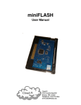
in the following picture.
IDE Registers
The IDE registers of the SuperIDE Interface are arranged in
the same order as the Glenside IDE Interface, making it
100% compatible with that product.
Register Offset
0
1
2
3
4
5
6
7
8
Function
Data
Error (read)/Features (write)
Sector count
Sector number
Cylinder low byte
Cylinder high byte
Device/head
Command
Latch
FLASH Bank Selection Register
This register is located just beyond the IDE registers, at
offset $09 from the base address setting of the interface.
6
Bit 7 of this register is the FLASH Enable bit. This bit is set
by the FLASH programming routine when writing to the
23
If this program is run on a CoCo 3, then additional options
are available to save a 32K ROM Cartridge, or even the
internal 32K ROM.
REMEMBER: For auto-start cartridges such as ROM
Paks, be sure to place a piece of tape over pin 8 so that
the cartridge does not auto-start. Also insure that DIP
Switch 1 of the SuperIDE Interface is in the OFF (Up)
position. Failure to do so will result in a crash when the
program starts the transfer!
ROMXFER.BAS
Like GETROM.BAS, this program also uses FLASH.BIN.
The convenience of ROMXFER is that it will transfer the
contents of a ROM Pak or disk controller’s EPROM in one
Multi-Pak slot to the desired FLASH bank in another MultiPak slot.
CHECKSUM.BAS
This program will provide a checksum on a ROM or bank of
FLASH, returning the sum of all bytes. A blank FLASH bank
should return the checksum value of 0, indicating that the
FLASH contains all zeros.
Now that the cover is off of your interface, let’s go over the
major parts of the circuit board.
40-pin IDE Interface
The 40-pin IDE connector allows you to connect one or two
external IDE hard drives via a 40-pin IDE ribbon cable.
ERASE.BAS
CPLD Programming Header
This program will erase a bank of FLASH by writing all $00s
to the specified bank.
This 10 pin header is used to update the logic in the Altera
CPLD.
IDEPROBE.BAS
Activity LED
This program will detect the drive or drives attached to your
interface and reports detailed information about each drive.
This LED is activated when reading or writing to the IDE bus.
Accesses to both the CompactFlash Socket as well as drives
on the 40-pin connector will cause the LED to activate. Its
location makes it easily visible on the left side of the
interface when plugged into a Multi-Pak, or in the front of the
CoCo when plugged directly into the CoCo’s cartridge port.
22
7
CompactFlash Socket
The CompactFlash Socket allows you to connect widely
available CompactFlash devices to the SuperIDE Interface.
The CompactFlash device in this socket can be configured
as either a master or slave. Please note that if the
CompactFlash socket is in use, you can only attach one
external hard drive to the 40-pin IDE connector.
IMPORTANT !!! NEVER, NEVER Insert or remove
A COMPACTFLASH in the socket while the POWER IS
ON! To do so may damage the SuperIDE Interface
and/or the CompactFlash!
5. Supplied Software
The supplied SuperIDE Utilities disk provides additional
software which can assist you in setting up your interface
and drives properly. We highly recommend that you work
from a backup of your original disk.
All BASIC programs are saved in ASCII format, and
therefore will load somewhat slower from the disk. To speed
up subsequent loads, LOAD, then SAVE the program back
to disk.
DIP Switches
FLASH.ASM/FLASH.BIN
The DIP switch block has three switches, and can be
accessed even with the cover in place. The switches are
labeled from right to left as 1, 2 and 3 and perform the
following functions:
These two files make up the FLASH programming routine
used by the included BASIC programs. The interface to the
routine is documented later.
Switch 1: This is the auto-start switch. If this switch is ON
(in the Down position), then the CART interrupt is triggered
upon power up. If this switch is OFF (in the Up position)
then the CART interrupt is not triggered on power up.
This switch is useful if you have an auto-start ROM, such as
a game, in the selected FLASH bank. You should NOT turn
the auto-switch on if your FLASH bank contains a DOS,
such as HDB-DOS.
Switch 2 and 3: Both of these switches are used to select
one of four 16K banks of the internal 64K of FLASH. The
following table show the settings:
Switch 2 Position
Switch 3 Position
8
FLASH.BAS
This program uses FLASH.BIN and allows you to program
the contents of a disk file into a FLASH bank of your
choosing.
GETROM.BAS
This program uses the assembly routines in FLASH.BIN and
allows you to save a ROM image from a controller or ROM
Pak to disk. When run, GETROM.BAS will prompt you for
the Multi-Pak slot where the ROM resides and the size of the
ROM. It will then obtain the ROM’s contents and save it to
the disk file specified.
FLASH Bank
21
The program will prompt you for the following information:
1.
2.
3.
4.
The base address of the SuperIDE Interface
The MPI slot of the SuperIDE interface
The FLASH bank where the DOS will be programmed
The name of the file to program
ON (Down)
ON (Down)
OFF (Up)
OFF (Up)
ON (Down)
OFF (Up)
ON (Down)
OFF (Up)
0
1
2
3
Once the information is provided, the file will be opened and
its contents transferred to the appropriate bank of FLASH.
Each of the four 16K banks can contain either a DOS (such
as Disk BASIC, HDB-DOS or A-DOS), or the contents of a
ROM Pak. We will learn later how to burn a ROM image into
the FLASH.
That’s all there is to programming the FLASH!
Jumper Block
The jumper block allows the setting of the interface’s base
address, as well the Flash Bank Selection Register (FBSR)
behavior on RESET/Power-Up.
There are 5 jumper pairs, for a total of 10 pins. Looking at
the pins from right to left, the bottom row of pins is odd
numbered (1, 3, 5, 7 and 9) and the top row of pins is even
numbered (2, 4, 6, 8 and 10). Each top and bottom pin
forms a pair that may or may not be covered with a shunt.
The following table shows the function of each of the five
pairs of jumpers:
Jumper Pair
1-2
3-4
5-6
7-8
9-10
20
Function if ON
FBSR
resets
on
power cycle
CompactFlash Socket
is MASTER
Bit 4 of base address
is SET
Bit 5 of base address
is SET
Bit 6 of base address
is SET
9
Function if OFF
FBSR resets on
RESET
CompactFlash
Socket is SLAVE
Bit
4
of
base
address is CLEAR
Bit
5
of
base
address is CLEAR
Bit
6
of
base
address is CLEAR
You will learn shortly how to set these jumpers for your
specific system setup.
Super Expansion Bus
The Super Expansion Bus is a Cloud-9 expansion
technology that allows addition of future peripherals to the
CoCo’s 40-pin bus, through two high-density 20-pin
connectors.
Real-Time Clock
If your SuperIDE Interface has a real-time clock, you will see
a 16 pin chip at this location. The real-time clock is always
addressed at $FF78-$FF79 and $FF7C, irrespective of the
base address of the IDE interface.
Configuring the Interface
In order to insure that your SuperIDE Interface matches your
Color Computer system, it is important to set the state of the
jumpers to reflect the proper base address as well as FBSR
reset behavior.
Setting the Base Address
As shipped, the interface’s base address is set up at a
default of $FF50 to $FF59. We recommend keeping this
setting if possible. In order to this, you must verify that no
other devices in your system conflict with this address
allocation.
If you do have a conflict then a base address must be
selected where there are no conflicts. The interface allows a
base address selection of $FF4X, $FF5X, $FF6X and
$FF7X. Jumper pairs 5-6, 7-8 and 9-10 allow you to select
one of these four base addresses.
One important note regarding base addresses: If your
SuperIDE Interface has a real-time clock, then $FF70 must
10
Option 2: Use ROMXFER.BAS to directly transfer the
contents of a ROM Pak or disk controller’s EPROM to a
FLASH bank (this requires a Multi-Pak).
For illustration, we will perform option #1.
Your first step is to choose the disk controller or ROM Pak
that contains the ROM you want to transfer to FLASH. If it is
a ROM Pak, you will need to place tape over pin 8 to
prevent the cartridge from auto-starting during the
transfer process. If it is a disk controller, then it isn’t
necessary to cover pin 8.
In either case, once the cartridge is properly prepped, insert
it into a free slot of the Multi-Pak. Slot 1 is usually a good
slot for this.
Put your SuperIDE Interface in slot 3 of the Multi-Pak, and
your floppy disk controller in slot 4. Be sure the slot
selection switch is set to 4.
Insert the SuperIDE Distribution Diskette into the floppy drive
and type:
RUN”GETROM”
Follow the prompts and supply a filename. The contents of
that disk controller or ROM Pak will be saved to the
filename.
When the program is complete, you will be returned to Disk
BASIC. Now, it is time to run the program to transfer the
ROM on disk into the FLASH on the interface.
To start, type:
RUN”FLASH”
19
NOT be used as a base address, as it will cause an
addressing conflict to occur.
4. Programming the FLASH
The SuperIDE Utilities disk that comes with your SuperIDE
Interface contains software to extract a ROM from a ROM
Pak or disk controller. It also contains software to program a
ROM image into any of the four FLASH banks on the
interface.
Typically you will want to program the FLASH on the
SuperIDE Interface if you intend to use it in a specific
application.
In such a scenario, the interface would be
plugged directly into the side of the cartridge port, with an
IDE-compatible DOS such as HDB-DOS in one of the
FLASH banks.
You may also want to just keep the SuperIDE Interface in a
slot in the Multi-Pak and have one or more ROM Paks
programmed into the FLASH, allowing them to be selected
on the fly.
Let’s take a look at different scenarios for programming the
FLASH using the supplied utilities.
Programming an Existing ROM into FLASH
To program a ROM Pak or disk controller ROM into the
FLASH, you have several options:
Option 1: Save a ROM Pak or disk controller EPROM’s
contents to disk using GETROM.BAS, then program the
desired FLASH bank in the SuperIDE Interface using
FLASH.BAS.
18
The following table shows how to set the jumper shunts
based on the desired base address. Please note that when
a jumper shunt is OFF, the corresponding bit is SET:
Address
$FF4X
$FF5X
$FF6X
$FF7X
J5-J6 (Bit 4)
Shunt OFF
Shunt OFF
Shunt OFF
Shunt OFF
J7-J8 (Bit 5)
Shunt ON
Shunt ON
Shunt OFF
Shunt OFF
J9-J10 (Bit 6)
Shunt ON
Shunt OFF
Shunt ON
Shunt OFF
Setting the FLASH Reset Behavior
The Flash Bank Selection Register (FBSR) is located at
offset $09 from the base address of the interface. At powerup, this register holds the value of DIP Switches 2-3, which
determine which of the four banks of 16K appear in the
CoCo’s ROM space at $C000. Software can modify the
value in this register to automatically select a different bank
of FLASH.
If jumper pair 1-2 contains a shunt, then the contents of the
FBSR will remain the same even through hardware reset,
and only a power cycle will cause the FBSR value to change
back to the DIP switch settings.
If jumper pair 1-2 does NOT contain a shunt, then contents
of the FBSR are reset to the state of the DIP switches upon
pressing the RESET button.
For a CoCo 1 or CoCo 2, we recommend that you keep the
shunt ON, since these Color Computers run from ROM.
Hence, pressing the RESET button insures that the last
value written to the FBSR remains, and that the
corresponding FLASH bank stays mapped into memory
space.
11
Reassembling the SuperIDE Interface
Now that you have configured your interface, you should
replace the top cover and secure it with the screw that you
removed earlier. Note that both the CompactFlash Socket
and the DIP Switches are still accessible even with the cover
in place. This allows you to easily switch FLASH banks or
the auto-start switch without having to remove the cover.
EXEC &HE010
Determining the Active FLASH Bank
You can determine which of the four banks of FLASH
memory is active by reading the FBSR. Type the following
(assuming the SuperIDE Interface’s base address is $FF50):
PRINT PEEK(&HFF59)
Adding Drives
Once you have configured the SuperIDE Interface, it is time
to hook one or more IDE drives. You can add up to two
drives to the system: a master drive and a slave drive. Each
of these drives must be set as master and slave in order to
be identified properly. Refer to your drive’s documentation
to determine how to set your drive as a master or slave.
If you want to use a CompactFlash card in the built-in CF
socket, then you can only add one hard drive to the bus via
ribbon cable.
In this case, you can also set the
CompactFlash to be a master or slave by shunting jumpers 3
and 4 on the on-board jumper block. Remember, if the
shunt is ON, the CompactFlash is a master, and the external
drive must be set as a slave. If the shunt is OFF, the
CompactFlash is a slave, and the external drive must be set
as a master.
Connecting to the CoCo
Now, it’s time to connect the SuperIDE Interface to your
Color Computer. Be sure that power is OFF on your Color
Computer and your Multi-Pak, then insert the SuperIDE
Interface is in slot 3. Your floppy disk controller should
reside in slot 4.
Once the controllers are firmly in place, turn on your MultiPak and then your Color Computer.
12
17
as Disk BASIC, HDB-DOS, A-DOS, etc. the following
commands will work on a CoCo 1/2:
POKE 113,0:POKE &HFF59,X (where X is the bank
0-3)
EXEC 40999
If the FLASH bank you are switching to contains a ROM Pak
image such as a game, be sure the auto-switch (DIP Switch
1) is in the OFF (Up) position, and type the following on a
CoCo 1/2:
POKE &HFF59,X (where X is the bank 0-3)
EXEC &HC000
Depending upon the contents of the target FLASH bank,
your CoCo may go into a crash mode. This is normal, due to
the fact that the ROM that BASIC is fetching instructions
from is actually being totally replaced at the point of the
POKE command. If this happens, press the RESET button
and the code should execute properly.
CoCo 3 FLASH Bank Software Switching
Depending on the type of ROM image, there are two
different methods for software selection of a FLASH bank. If
you are switching to a FLASH bank containing a DOS such
as Disk BASIC, HDB-DOS, A-DOS, etc. the following
commands will work on a CoCo 3:
POKE &HFF59,X (where X is the bank 0-3)
POKE 113,0:DLOAD
If the FLASH bank you are switching to contains a ROM Pak
image such as a game, be sure the auto-switch (DIP Switch
1) is in the OFF (Up) position, and type the following on a
CoCo 3:
POKE &HFF59,X (where X is the bank 0-3)
16
13
Hardware Switching
3. Using the FLASH
One of the innovations of the SuperIDE Interface is its
utilization of FLASH memory technology to store ROM code.
This technology totally replaces the antiquated EPROM that
is found on older floppy and hard drive controllers.
Unlike EPROMs, FLASH memory brings several benefits to
Color Computer users. First, FLASH can be programmed incircuit, without any additional hardware. Second, FLASH
technology delivers a large amount of storage in an
extremely small footprint. This allows multiple ROMs to be
stored in the same chip and selected via hardware or
software by the user.
How the FLASH is Partitioned
The SuperIDE Interface contains 64K of internal FLASH,
which is partitioned into four banks: bank 0, bank 1, bank 2
and bank 3. Each bank can hold 16K of code.
Typically, a ROM image will reside in each bank. These
ROM images can be DOS’s such as Disk BASIC, HDB-DOS
or A-DOS, etc, or they can be ROM Paks, such as games
and applications.
While all banks can hold code, only one bank is active at any
given time. It is up to the user to determine which bank will
hold code, and to which bank the interface will start from at
power-on.
There are two methods of FLASH bank selection: the
hardware switching method and the software switching
method.
14
DIP Switches 2 and 3, located on the side of the SuperIDE
Interface, can select bank 0, 1, 2 or 3 as the desired bank to
reference on power-up. Simply set up the switches for the
desired bank to be active. Due to the location of the DIP
Switch on the interface, we recommend that you turn OFF
your system and remove the SuperIDE Interface to properly
set the switch.
If the desired FLASH bank contains a DOS such as Disk
BASIC, HDB-DOS, A-DOS, etc., then the auto-start switch
(DIP Switch 1) should be in the OFF (Up) position.
Conversely, if the desired FLASH bank contains a ROM Pak
game image, you can elect to turn on the auto-start switch.
This will cause the game to auto-start when your CoCo is
powered up.
Software Switching
Use of the FLASH Bank Selection Register (FBSR) allows
you to switch to a ROM in a specific FLASH bank without
necessarily having to power down your CoCo.
The
procedure for software switching between a CoCo 1/2 and a
CoCo 3 are slightly different, due to the fact that the CoCo
1/2 runs BASIC from ROM, whereas the CoCo 3 runs BASIC
from RAM.
The FBSR is located at offset $09 from the base address of
the SuperIDE Interface. So for example, if the interface
base address is $FF50, then the FBSR is at $FF59.
CoCo 1/2 FLASH Bank Software Switching
Depending on the type of ROM image, there are two
different methods for software selection of a FLASH bank. If
you are switching to a FLASH bank containing a DOS such
15