1
TABLE OF CONTENTS
Features and Controls,
Installation Guidelines
Input Connections
Connecting a CD, DVD or tape player or tuner
Connecting an equalizer or signal processor
Stereo or Mono Inputs
Speaker connecitons
Bridged Mode Operation
Connecting to standard AC power
Mounting the amplifier
Turning the amplifier on
Using the power LED meter
Using the channel1 and channel2 output level controls
About the internal clip circuitry
Specifications
Limited warranty
PREAMP OR MIXER
B A LA N C E D IN P U T S
INPUTS
CH-2
VOLTAGE
OUTPUTS
CH-2
CH-1
CH-1
POWER CONSUMPTION :
~AC iN
115/230V-60/50 Hz
BRIDGE
CH-1
STEREO
GND
MONO
BRIDGE
GROUND LIFT
CH-2
LIFT
FUSE
GROUND
SCREW
LOW CAPACITANCE SHIELDED WIRE
Input connections
These amplifiers accept a broad range of input sources,
including Compact Disc (CD) players; DVD, Cassette, Reelto-Reel or other tape players; Radio Tuners; Equalizers;
Signal Processors.
Please read this manual throughly before you attempt to set up and use the amplifier. It contains a
range of installation suggestions as well as instructions to ensure safe usage. Installed properly, you
can expect years of trouble-free service from this product.
Channel 1 and Channel 2 Power LED Display
Indicate the output signal level for each channel.
FEATURES AND CONTROLS
INSTALLATION GUIDELINES
Connecting the GND (Ground) screw terminal
Connecting a mixer or preamplifier may cause excessive
noise or hum in the amplifier output. To prevent this,
connect one end of a low-capacitance shielded wire to the
amplifier’s ground screw (on the rear panel). Then connect
the other end of this wire to the ground terminal on the
mixer or preamplifier enclosure.
GND
1
2
2
2
2
2
2
3
3
3
3
3
3
3
4
H O T(+)
C O L D (-)
Your New PYLE PPA series P.A.
Amplifier gives you the power and
versatility you need in a professional
sound system.
The amplifier's wide frequency
response makes it suitable for
amplifying music or vocal program
material. It can be used for live bands,
office paging systems, public
announcements, or a variety of other
installations.
Connecting a CD or DVD or tape player or tuner
In a normal installation, one would use the RCA JACKS for
connecting a CD player, DVD, tape player or tuner.
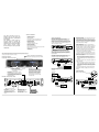
FRONT PANEL, PPA200, PPA300, PPA450
GND
HOT (+ )
COLD(-)
BALANCE D INPUT S
INPUTS
CH-2
VOLTAGE
OUTPUTS
CH-2
CH-1
• Speakers which are connected to the same channel are
part of a pair, and must be of the same impedance.
• Speakers connected to different channels are NOT part
of a pair, and can be of different impedances.
1. Prepare the speaker wire by removing about 1 inch of
insulation from the end of the speaker wire you intend to
connect to the amplifier. Then twist the exposed wire to
secure all the wire strands.
NOTE: Use 16-gauge speaker wire for lengths up to25
feet; 14-gauge wire for lengths over 25 feet. It is
recommended that you use the shortest length of wire
possible.
POWER CONSUMPTION :
2. Connect the speaker wires to the speaker's positive and
negative terminals.
MONO
STEREO
Speaker connections
You can connect 4 Ohm, 8 Ohm or 16 Ohm speakers to
Channel 1 and/or Channel 2 of the amplifier. If you connect
two pairs of speakers, be sure to follow these guidelines:
~AC iN
115/230V-60/50 Hz
CH-1
BRIDGE
CH-1
BRIDGE
GND
Stereo or Mono Inputs
Your PYLE PPA amplifier can be operated in Stereo, Mono
or Bridged mode, depending on the input source. If the
input signal is mono, slide the Stereo/Mono/Bridged selector
switch to MONO and the signal will be routed through both
channels. If you wish to run the amplifier in bridged output
mode, slide the switch to Bridged.
GROUND LIFT
CH-2
LIFT
FUSE
PPA450
4500 Watt
CD PLAYER, DVD , TAPE PLAYER
OR TUNER
use RCA jacks
3. Connect the speaker wires to the amplifier's left and
right speaker terminals according to the terminal color
polarity.
Power On/Off
Channel 1 and Channel 2
Output Level Controls
Lets you adjust the sound levels
for each channel.
Fan Cooling
Cooling system is automatically activated
whenever amplifier is turned on. This forced
air cooling system rapidly exhausts interior
heat, reducing operating temperature and
aiding performance.
Protection Circuit and Indicator
The indicator will be illuminated when
the amplifier is powered on and at turnon delay status; the indicator will be
turned off after internal outputs are
connected. The indicator will also be
illuminated when the amplifier has
abnormal problems, such as overload
or excessive heat.
NOTE: Most speaker terminals are either color-coded
or have a mark that indicates the terminal's polarity.
Usually positive terminals are red or have a plus symbol
(+), and negative terminals are black or have a minus
symbol (-).
Connecting an equalizer or external signal processor
Connect the processor’s OUT to the amplifier’s INPUT
connectors.
STEREO OPERATION
EQ OR MIXER
SWITCH IN “STEREO” POSITION
-OR–
REAR PANEL, PPA200, PPA300, PPA450
GND
HOT (+ )
COLD(-)
BALANCE D INPUT S
INPUTS
CH-2
VOLTAGE
OUTPUTS
CH-2
CH-1
CH-1
CH 2
POWER CONSUMPTION :
~AC iN
115/230V-60/50 Hz
CH 1
BRIDGE
CH-1
STEREO
GND
GND
CH-2
BRIDGE
GROUND LIFT
CH-2
VOLTAGE
OUTPUTS
CH-2
CH-1
CH-1
POWER CONSUMPTION :
LIFT
FUSE
GND
BAL ANCED I NPUTS
INPUTS
HOT (+ )
COLD(-)
HOT(+)
COLD(-)
BALANCED INPUTS
MONO
INPUTS
~AC iN
115/230V-60/50 Hz
CH-2
VOLTAGE
OUTPUTS
CH-2
CH-1
CH-1
POWER CONSUMPTION :
~AC iN
115/230V-60/50 Hz
BRIDGE
CH-1
BRIDGE
CH-1
STEREO
GND
STEREO
GND
MONO
MONO
BRIDGE
GROUND LIFT
CH-2
BRIDGE
LIFT
GROUND LIFT
FUSE
CH-2
EQ OR MIXER
LIFT
FUSE
T4 AL 250V for 110~120V
T2 AL 250V for 220~240V
STEREO SIGNAL SOURCE
use XLR/6.35 mm
combo jacks
Input Jacks
Let you connect a variety of audio
input sources via the balanced
(XLR/6.35mm phone jack
combinations) or unbalanced (RCA)
inputs.
Stereo/Mono Switch
Lets you select conventional
stereo operation with a
stereo input signal or bridged
mono input mode.
CAUTION! Do not use
balanced and unbalanced
inputs simultaneously!!