1
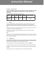
Instruction Manual This covers the Burco Synergy Grill SYNG01 444449877 Glen Dimplex Professional Appliances Stoney Lane, Prescot, Merseyside, L35 2XW Tel: 0844 815 3755 Fax: 0844 815 3748 Email: [email protected] www.burco.co.uk Instruction Manual INSTALLATION and SERVICING INSTRUCTIONS This appliance must be installed and serviced by a competent person as stipulated by the Gas Safety (Installation & Use) Regulations. IMPORTANT The Installer must ensure that the installation of this appliance is in conformity with these instructions and National Regulations in force at the time of installation. Particular attention must be paid to : Gas Safety (Installation & Use) Regulations Health & Safety Law – HSE Local & National Building Regulations Fire Precautions Act This appliance is CE marked on the basis of compliance with the Gas Appliance Directive for the Countries, Gas Types and Pressures as stated on the Data Plate. WARNING – THIS APPLIANCE MUST BE EARTHED It is most important that these instructions be consulted before installation and commissioning of this Grill. Failure to follow the installation guidance here-in may invalidate any warranties. These instructions are only valid for units where the Data Plate states either of the following Country Codes: GB, IE. (United Kingdom & Eire) If any other country is specified on the Data Plate then these instructions should not be used and the manufacturer should be contacted. THIS APPLIANCE IS NOT INTENDED FOR USE BY PERSONS OF REDUCED PHYSICAL, MENTAL OR SENSORY CAPABILITIES (INCLUDING CHILDREN) OR LACK OF EXPERIENCE AND KNOWLEDGE, UNLESS THEY HAVE BEEN GIVEN SUPERVISION OR INSTRUCTION CONCERNING USE OF THE APPLIANCE BY A PERSON RESPONSIBLE FOR THEIR SAFETY Instruction Manual SECTION 1 – INSTALLATION UNLESS OTHERWISE STATED, PARTS & MATERIALS WHICH HAVE BEEN SUPPLIED & PROTECTED BY THE MANUFACTURER ARE NOT TO BE ADJUSTED BY THE INSTALLER. 1.1 Model Numbers, Nett Weights and Dimensions MODEL WIDTH mm DEPTH mm HEIGHT mm SYNERGY GRILL 450 600 360 1.1 WEIGHT kg 48.5 GAS CONNECTION 1/2" BSP SITING It is recommended that there should be sufficient clearance all around the grill from any combustible wall or object liable to damage when overheated. It is also advised that a minimum of 100mm clearance should be allowed to facilitate access to the gas connector at rear. There must be a minimum vertical clearance of 900mm above the cooking area to ensure no overheating of overlaying combustible surfaces. The front panel of your Synergy Grill should be kept clear of any obstructions to allow maintenance of the unit. Note Upper sections of the unit are designed to stay relatively cool when compared to other types of grill, however, as a precaution the unit should be positioned in a manner which minimises the risk of accidental touching. 1.2 VENTILATION The grill MUST be installed level in a well lit and draught free position. Adequate ventilation, whether natural or mechanical, must be provided to ensure sufficient air for combustion and removal of combustion products, which may be harmful to health. Recommendations for Ventilation of Catering Appliances are given in BS5440:2. For multiple installations, requirements for individual appliances should be added together. Installation should be made in accordance with local and/or national regulations applying at the time. Positioning the grill below a ventilated canopy is the most suitable arrangement. Instruction Manual Warning Remember, dirty extraction filters become combustible, hence the importance of adhering to the stated clearance distance to these items. Regular cleaning of extraction filters must be carried out. 1.3 GAS SUPPLY The incoming service must be of sufficient size to supply the full rate without excessive pressure drop. A gas metre may be connected to the service pipe by the Gas Supplier. An existing metre should be checked, preferably by the Gas Supplier, to ensure that it is adequate to cope with the rate of gas supply required. Installation pipes should be fitted in accordance with IGE/UP/2. Gas pipe-work size, from the metre to the unit, must not be less than the appliance inlet connection, Rp ½ (1/2” BSP). An isolating cock must be located close to the appliance (on the inlet side of the governor on Natural Gas models) to allow shut down during an emergency or routine service. The installation MUST BE TESTED FOR GAS SOUNDNESS, details of which can be found in IGE/UP/1 1.4 ELECTRICAL SUPPLY Electrical supply is via a normal 3 pin plug. Connection is to a normal 240v supply in the UK and Eire. Warning – THIS UNIT MUST BE EARTHED 1.5 GAS SUPPLY A pressure test point is accessible upon removal of the control panel. This point is located directly beneath the burner unit. The screw can be seen as part of the brass gas connection unit. 1.6 BURNER ADJUSTMENT Burner Aeration The burners are fitted with fixed injectors. No adjustment should be undertaken by the user. 1.7 INJECTOR SIZES Your Synergy Grill is fitted with the injector size that is required for the version you have purchased. Natural Gas Units are fitted with a 2.2 mm Injector and the LPG Units are fitted with a 1.5 mm Injector. Conversion of units from one type of gas to another should only be undertaken by a qualified engineer. Instruction Manual SECTION 2 – ASSEMBLY AND COMMISSIONING 2.1 ASSEMBLY CAUTION – THIS UNIT IS HEAVY AND SHOULD BE HANDLED BY 2 PEOPLE 2.1.1 Grill Unit Unpack grill and check that all components are undamaged. To unpack, lift off the top box to expose the inner box. Parts supplied within separate inner box are specified in the contents list below: Ceramic Unit x 1 Cast-Iron Grills x 2 Fulham Gas Connector Conversion Date Sticker Ceramic Extractor Tools x 2 Cooking Grid x 1 Jet (1.5mm if unit purchased as a NG product & 2.2mm if the unit purchased as an LPG Product). This facilitates the ability to convert to either gas type. 2.1.2 Assemble of the Ceramic Units, Cast Iron Grids & Cooking Grid a When the unit has been installed in a desired location, the Ceramic Unit, Cast Iron Grid and Cooking Grid can be installed: Remove the grill from the packaging. Due to the weight of the product, it is recommended at least two people lift the product out of the box. Remove the cooking grid and splash back. Unpack the ceramic plates and place them over the burner into the bottom of the unit taking care of the gas burner in the centre of the grill base. Place the ceramic burner cap on top of the burner. Place the two cast iron grills on top. Ensure there’s a gap between the cast iron grid and the sides of the unit as contact will cause the external surfaces to get hot when the machine is in use. Fit the splash back on top of the grill - this should click into place. The cooking grid can now be slid on and sits on the locator pins on the splash back. Instruction Manual 2.2 CONNECTION TO THE GAS SUPPLY Installation should be carried out in accordance with the various regulations listed on the cover of this document. Ensure that a gas isolating cock is fitted to the supply at a convenient proximity to the grill. 2.3 CONNECTION TO AN ELECTRICAL SUPPLY Electrical supply is via a normal 3 pin plug. Connection is to a normal 230v supply in the U.K. and Eire. Warning – THIS UNIT MUST BE EARTHED 2.4 CONNECTION TO A WATER SUPPLY Not applicable to this appliance. 2.5 COMMISSIONING 2.5.1 Testing and Purging Pressure test the gas installation for soundness and purge any air from the supply. 2.5.2 Gas Pressure and Burner Flame Adjustment a Remove Right Side Panel b Fit a pressure gauge to test point and light grill c With unit turned on the gas pressure reading should be 20Mb – Natural Gas or 28-30/37 Mb – LPG and a steady Light Blue (Cyan) Flame should be observed at burner. d With gas control in the ON position, check the flame cone is approximately 10mm in length. Note FLAME position is set at factory. Re-setting is NOT necessary 2.5.3 Soundness Checking and Re-assembly Whilst grill is lit, test all integral gas carrying joints and components for gas soundness. Use a suitable leak detection fluid. TURN OFF gas control tap. REMOVE pressure gauge and replace test point sealing screw. ENSURE A GAS TIGHT JOINT IS MADE. Re-assemble all panels and components removed during installation and commissioning. The wire cooking grid can then be placed in position. Instruction Manual SECTION 3 – SERVICING and CONVERSION Important Before carrying out any inspection, servicing or exchange of components, turn OFF the gas at the isolating cock and take steps to ensure that it is not inadvertently turned on. Always remove the Top Unit and Cooking Grid. Remember to Isolate the Electricity Supply. After any maintenance task, check the appliance to ensure that it performs correctly and carry out any necessary adjustments as detailed in Section 1. After carrying out any servicing or exchange of gas carrying components – ALWAYS CHECK FOR GAS SOUNDNESS 3.1 GAS CONVERSION CHECK LIST To convert from NATURAL to PROPANE gas – Change injectors (Remove 2.2mm jet – Replace with 1.5mm jet) Change data plate To convert from PROPANE to NATURAL gas – Change injectors (Remove 1.5mm jet – Replace with 2.2mm jet) Change data plate 3.2 REMOVAL and Replacement of BURNER a Remove Cooking Grid, Cast Iron Grid and Ceramic Units b Unscrew 4 x Screws at base of Dome Unit. c Carefully replace unit ensuring cut-out around ignitor is in correct position. 3.3 REMOVAL OF INJECTOR Following removal of burner, the injector may be cleaned or replaced as desired. See Section 1.7 for injector dimension details. 3.4 BURNER and INJECTOR CLEANING Burners require to be cleaned periodically to ensure that ports are free from blockage. This may be facilitated by means of wire brushing. Individual ports may be cleared with a suitable metal instrument. Dislodged material should then be shaken out of the open burner end. Should it become necessary to wash the burner (s), ensure that they are completely dry and free from cleaning materials before re-fitting to the appliance. Instruction Manual Upon re-fitting, check adjustment and flame picture as described in Section 2.5.2 of this document. 3.5 IGNITION/FLAME SENSOR DEVICE N.B. – ISOLATE FROM ELECTRICAL AND GAS SUPPLY a Remove Front and/or side panel b Undo 1 x screw which secures unit to base of chamber c Remove other end of wire from controller unit d Withdraw faulty unit and replace Instruction Manual USER INSTRUCTIONS SECTION 1 SECTION 2 SECTION 3 SECTION 4 SECTION 5 - GENERAL DESCRIPTION LIGHTING and OPERATIONS COOKING HINTS CLEANING and MAINTENANCE IMPORTANT SAFEGUARDS This appliance has been CE-marked on the basis of compliance with the Gas Appliance Directive for the Countries, Gas Types and Pressures as stated on the Data Plate. These Appliances MUST BE installed by a competent person in compliance with the INSTALLATION AND SERVICING INSTRUCTIONS and National Regulations in force at the time. Particular attention MUST be paid to the following: Gas Safety (Installation & Use) Regulations Health & Safety at Work Act Furthermore, if a need arises to convert the Appliance for use with another gas, a competent person must be consulted. Those parts which have been protected by the manufacturer MUST NOT be adjusted by the User. Users should be conversant with the appropriate provisions of the Fire Precautions Act and the requirements of the Gas Safety Regulations in particular the need for regular servicing by a competent person to ensure the continued safe and efficient performance of the Appliance. Upon receipt of the User’s Instruction manual, the installer should instruct the responsible person (s) of the correct operation and maintenance of this appliance. This equipment is ONLY FOR PROFESSIONAL USE, and shall be operated by QUALIFIED persons. It is the responsibility of the Supervisor or equivalent to ensure that users wear SUITABLE PROTECTIVE CLOTHING and to draw attention to the fact that, some parts will, by necessity, become VERY HOT and will cause burns if touched accidentally. SECTION 1 – GENERAL DESCRIPTION Your Synergy Grill is supplied with all the necessary components for use of the grill as intended. Your Synergy Grill is fitted with a single flame failure device and full sequence ignition control board. A brass injector and data plate sticker is enclosed separately within the packaging. These parts are required only if you wish to have your grill converted to LP Gas (if currently set up for Natural Gas) or for Natural Gas (if currently set up for LP Gas). Please see Data Plate to ascertain current set up. We suggest you keep these parts safe for any future requirement. Please note, any conversion to the grill should only be undertaken by a qualified and approved technician. Please contact your supplier for further information. NO FAT DRIP TRAY IS REQUIRED FOR YOUR SYNERGY GRILL Instruction Manual SECTION 2 – LIGHTING and OPERATIONS TO LIGHT THE BURNER – Note that no pilot light is required for your Synergy Grill Ensure your Synergy Grill is supplied with gas and electricity as detailed in your installation instructions. Proceed as follows: 1) Push control switch to Ignition/On position The burner will light and cooking can commence once cooking temperature is reached. In the unlikely event that the burner does not light, the unit will try to ignite (spark) 3 times before going into ‘safe’ or ‘lockout’ mode. If this happens the RED neon on the front of the appliance will illuminate and gas supply will be cut off to the appliance. To reset the appliance for normal operation switch the appliance off (for 30 seconds) and back on again and the burner will re-ignite. If you are still experiencing problems, please contact your supplier. Warning IF BURNER IS EXTINGUISHED INTENTIONALLY OR OTHERWISE, THE APPLIANCE SHOULD BE TURNED OFF. NO ATTEMPT TO RELIGHT THE GRILL SHOULD BE MADE UNTIL, AT LEAST THREE MINUTES HAVE ELAPSED. Turning the Burner OFF Simply push the switch to the ‘Off Position’ ALWAYS TURN THE BURNER OFF WHEN NOT IN USE Your Synergy Grill requires very short ‘warm-up’ time and you can have the confidence to switch-off the grill when not required. Pre-heating Unlike other radiant grills, your Synergy Grill requires only a few minutes from cold to reach a satisfactory cooking temperature. Warning DO NOT DRAPE TOWELS etc OVER THE APPLIANCE WHILST IT IS IN USE. SUCH ACTION COULD OBSTRUCT VENTILATION AND LEAD TO OVERHEATING. Instruction Manual SECTION 3 – CLEANING & MAINTENANCE Warning – Disconnect the appliance from the mains supply before cleaning and allow to cool. Important: do not use any abrasive cleaning fluids or materials. Daily Cleaning STAINLESS STEEL Wipe over top with warm soapy water. A mild detergent on a cloth can be used for stubborn stains. Rinse with clean water and dry with a soft dry cloth. Note – the top of the unit can be removed to aid this process. CERAMIC REFLECTOR UNIT This area will need very little cleaning and should simply be brushed with a soft brush and vacuumed with a hand vacuum cleaner if required. BURNER UNIT You can clean the burner should you wish with a wire brush, please remove the ceramic cover before brushing. COOKING GRID Steep grid in hot soapy water, run with pan scrubber on stubborn stains. CAST IRON GRID – Requires no cleaning Section 5 - Important safeguards Do not use this appliance if it has malfunctioned or has been damaged in any way. Always switch off the appliance when not in use or when cleaning. This appliance is not suitable for installations in an area where a water jet could be used. This appliance is not intended for use by persons of reduced physical, mental or sensory capabilities (including children) or lack of experience and knowledge, unless they have been given supervision or instruction concerning use of the appliance by a person responsible for their safety. This appliance must not be cleaned by a water jet. This appliance is only to be installed in locations where its use and maintenance is restricted to trained personnel. For correct operation this appliance should be operated in an ambient temperature between 20-30 degrees Celsius. Do not use accessories or attachments which are not recommended or sold by Synergy as they can cause hazards. Instruction Manual Guarantee This appliance is guaranteed against defective materials or faulty workmanship. For length of guarantee please contact your supplier. This guarantee is given subject to the hob being used in accordance with the instructions on the supply voltage marked on it and to the usual fair wear and tear conditions. The guarantee does not cover consequential damage arising out of any failure acceptable under guarantee, nor does it cover damage resulting from misuse, accident or unauthorised alterations to the grill. In any communication with the supplier or manufacturer, it is essential to quote the catalogue number marked on the grill. Proof of purchase will be required. In any communication with the service department, it is essential to quote the model and serial number marked on the rating label. This guarantee, in no way diminishes the buyer’s statutory rights. Burco products are intended for commercial use as detailed in these instructions. Burco has a policy of continuous improvement in product quality and design. The Company, therefore, reserves the right to change the specification of its models at any time. Model SKU Number Dimensions in mm Weight in Kg Electrical supply H W D SYNG01 444449877 490 450 600 48.5 230V/50Hz Instruction Manual Customer helpline For spares and after-sales service please contact Burco on: T: 0844 815 3737 F: 0844 248 4123 E: [email protected] Glen Dimplex Professional Appliances, A Division of Glen Dimplex Home Appliances Stoney Lane, Prescot, Merseyside L35 2XW www.burco.co.uk