1
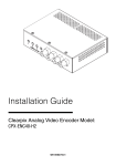
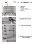
User Manual Revision 2 The CPX-ENS Wireless Alarm Voice Equipment Emergency Notification System 140 Westwoods Drive, Liberty, MO 64068 866.932.6317 Table of Contents 1. IMPORTANT INFORMATION 1.1 General Description 1.2 Limited Warranty & Disclaimer 1.3 DISCLAIMER – Important Information 1.4 Safety 1.5 FCC Compliance 1.6 Recommended Routine Maintenance 2. OPERATING THE CLEARPIX ENS 2.1 Touch Screen 2.2 Key Switch 2.3 Start Screen 2.4 Keyboard 2.5 External Connections 2.6 System Status Icons 3. ARMED MODE 3.1 Arming the System 3.2 Disarming the System 3.3 Real Time Alarms 3.4 Supervisory Alarms 3.5 Alarm Reports 4. CONFIGURATION MODE 4.1 Configuring the System 4.2 User Zones 4.2.1 Printing a User Zones List Report 4.2.2 Modify Zone 4.2.3 Delete Zone 4.2.4 Add User Zone 4.2.5 Audio Message 4.2.6 Zone Number 4.2.7 Description 4.2.8 Schedule 4.2.9 Entry/Arm Delay 4.2.10 Repeats 4.2.11 Reset Required/No Reset Required 4.2.12 Actions - Initial 4.2.13 Radios 4.2.14 Repeats 4.2.15 Speakers 4.2.16 Email 4.2.17 Actions - Escalated 4.2.18 Email 4.2.19 Commit Changes 4.3 Points 4.3.1 Printing a Points List Report 4.3.2 Add Point 4.3.4 Point Number 4.3.5 Point Type 4.3.6 Zone Cfg (zone configuration) 4.3.7 Enroll Point 4.3.8 Status 4.3.9 Zone 4.3.10 Description 4.3.11 Active State 4.3.12 Clear Mode 4.3.13 Commit Changes 4.3.14 Modify Point 4.3.15 4.4 4.4.1 4.4.2 4.4.3 4.4.4 4.4.5 4.4.6 4.4.7 4.4.8 4.4.9 4.5 4.5.1 4.5.2 4.5.3 4.5.4 4.5.5 4.5.6 4.5.7 4.6 4.6.1 4.6.2 4.6.3 4.6.4 4.6.5 4.6.6 4.7 4.7.1 4.7.2 4.8 4.9 4.9.1 4.9.2 4.10 4.11 4.12 4.12.1 4.13 5 5.1 5.1.1 5.1.2 5.1.3 5.2 5.2.1 5.2.2 5.2.3 5.2.4 5.2.5 5.2.6 5.2.7 5.2.8 5.3 Delete Point Schedules Printing a Schedules List Report Add Schedule Schedule Name Enable Suppression Periods Add Period Commit Changes Modify Schedule Delete Schedule Contacts Printing a Contact List Report Add Contact Name Phone Email (to send emails & text messages) Modify Contact Delete Contact Radios Battery Voltage Power Delay Audio Level CTT Period CTT Retries PTT Delay Supervisory Zones Printing a User Zones List Report Modify Zone System Settings Relays Output Relay Expansion Boards Input Relay Expansion Boards Email Setup Network System Information Update Firmware Factory Settings THE WEB INTERFACE Viewing Real Time Alarms and Printing Reports from the Web Interface User Manual Arm/Disarm Reports Configuring the System from the Web Interface Login Reports System Settings Zones Points Schedules Contacts Network and eMail Enrolling a Virtual Button 1. Important Information 1.1 General Description The ClearPix ENS receives alarm signals and transmits the voice messages associated with them over a radio network, telephone or speaker. It can be used with conventional or trunked radio systems. The system is set up with location specific zones, each of which has a recorded message attached to them. Any number of sensors can be set up as points that trigger a zone. The ClearPix ENS can also send emails and text messages when an alarm signal is received. There are three input relays (dry contacts) on the control panel and a wireless receiver. Over 10,000 wireless sensors can be connected to the ClearPix ENS. There are a wide range of wireless sensors available. There are three relay outputs (dry contacts) that can be used to activate other equipment when an alarm is activated. Relay expansion boards can be added to the system. Virtual panic buttons can be installed on any computer within a local area network (LAN) in which the ClearPix ENS is included. The virtual buttons are an icon on a computer screen which will generate an alarm when it is double clicked. The ClearPix ENS can be configured to accept input from or provide output to other automated systems through the OEM module. This enables other systems such as access control and fire alarm systems to trigger an alarm or respond to an alarm triggered by the ClearPix ENS. The system is setup and configured using the touch screen on the front of the control panel. Alarm zones can be automatically enabled or disabled based on a user-defined schedule. Schedules can be configured to suit the user’s needs by hour and day of the week. The ClearPix ENS can generate reports which can be downloaded to a flash drive. 1.2 Limited Warranty & Disclaimer ClearPix Technology Systems, Inc. (“ClearPix Technology”) hereby warrants to the original purchaser (“Buyer”) that for a period of two (2) years following the date of delivery, all parts supplied by ClearPix Technology will be free from defects in workmanship and material. During such period ClearPix Technology will, without cost to Buyer, at ClearPix Technology’s option, either (i) repair any such defective materials; (ii) furnish replacement materials; or (iii) grant a credit to Buyer’s account in the amount of Buyer’s net purchase price of such defective materials. Defects caused by third parties; acts of God; installation by any party other than ClearPix Technology or ClearPix Technology’s authorized agents; abnormal or improper use or stress; or failure to maintain the CLEARPIX ENS system in accordance with ClearPix Technology’s recommendations are specifically excluded from the coverage of this warranty. THE FOREGOING LIMITED WARRANTY IS EXCLUSIVE AND IS GIVEN AND ACCEPTED IN LIEU OF ANY AND ALL OTHER WARRANTIES EXPRESS OR IMPLIED, INCLUDING, WITHOUT LIMITATION, THE IMPLIED WARRANTIES OF MERCHANTABILITY AND FITNESS FOR A PARTICULAR PURPOSE, AND ALL OTHER REMEDIES. THESE ARE THE ONLY REMEDIES OF BUYER FOR ANY BREACH OF WARRANTY OR ANY OTHER CLAIM RELATING TO THE CLEARPIX ENS SYSTEM. CLEARPIX TECHNOLOGY’S TOTAL LIABILITY ARISING OUT OF SUPPLYING OF THE CLEARPIX ENS SYSTEM, OR THE USE OF THE CLEARPIX ENS SYSTEM, WHETHER ON WARRANTIES OR CLAIM OF NEGLIGENCE, OR OTHERWISE, SHALL NOT IN ANY CASE EXCEED THE COST PAID BY BUYER TO CLEARPIX TECHNOLOGY FOR THE CLEARPIX ENS SYSTEM AND IN NO CASE SHALL CLEARPIX TECHNOLOGY BE LIABLE TO BUYER OR ANY THIRD PARTY FOR ANY INCIDENTAL, CONSEQUENTIAL OR SPECIAL DAMAGES. Copyright © 2013 & 2014, ClearPix Technology Systems, Inc. 1 1.3 DISCLAIMER – Important Information ClearPix Technology Systems Inc. does not claim that the product(s) may not be compromised and/or circumvented, or that the product will prevent any death, personal and/or bodily injury and/or damage to property resulting from burglary, robbery, fire, or otherwise, or that the product(s) will in all cases provide adequate warning or protection. ClearPix Technology Systems Inc. shall have NO liability for any death, injury or damage, however incurred, based on a claim that ClearPix Technology Systems product(s) failed to function. The user of the product(s) is strongly advised to conduct product and systems tests at least monthly. Changes in environmental conditions, electric or electronic disruptions and tampering or abuse may cause the product(s) not to perform as expected. Product Changes: We reserve the right to discontinue a product or make design and specification changes at any time without notice. 1.4 Safety In installation and use of these products, you must comply with the National Electrical Code or any other applicable safety codes. During installation, turn off all power and take all necessary precautions to prevent injury. The potential for electric shock is present if the system is plugged into AC power. Hazardous voltages are present inside the inner enclosure. Never open the inner chassis unless the system is first unplugged. Do not apply power until all wiring is completed. Never replace a fuse with a value other than the original value and type. While charging, lead acid batteries release small amounts of flammable gasses, which can collect in the sealed case. Keep away from sparks or flame. Federal Law requires you to disconnect the battery before shipping or storing the ClearPix ENS control panel. CAUTION RISK OF EXPLOSION IF BATTERY IS REPLACED BY AN INCORRECT TYPE. DISPOSE OF USED BATTERIES ACCORDING TO THE INSTRUCTIONS 1.5 Power The ClearPix ENS control panel should be plugged into a properly grounded standard AC outlet during normal operation. The input ratings are: 120VAC-240VAC, 1.3A, 50 or 60 Hz. 1.6 FCC Licensing This equipment has been tested and found to comply with the limits for a Class B digital device, pursuant to Part 15 of the FCC Rules. These limits are designed to provide reasonable protection against harmful interference in a residential installation. This equipment generates, uses, and can radiate radio frequency energy and, if not installed and used in accordance with the instructions, may cause harmful interference to radio communications. However, there is no guarantee that interference will not occur in a particular installation. Changes or modifications not expressly approved by the manufacturer for compliance could void the user’s authority to operate the equipment. The ClearPix ENS also complies with the Class A (commercial use) requirements of part 15 of the FCC rules. Copyright © 2013 & 2014, ClearPix Technology Systems, Inc. 2 1.7 Recommended Routine Maintenance Scheduled Testing Each day, week or month at least one random button in the system should be tested on your live radio network. Before you press the button, notify anyone monitoring your radio network that you will be testing the ClearPix ENS system so that they do not respond to the alarm that is transmitted. Be sure to check that the message that is transmitted over the radio network matches the location of the button that was pressed. Quarterly Testing Before you begin, notify anyone monitoring your radio network that you will be testing the ClearPix ENS system. Open the front panel of your system and switch the radio channel in your box to “TEST”. You should have a verified list of button locations and a handheld, test radio set to the right frequency. If your system includes a radio that was supplied by ClearPix Technology, the default test frequency is 151.475 VHF or 465.650 UHF. Walk around pushing each button and make sure that the correct message is broadcast over your test radio. When you are done testing all of the buttons, be sure to switch the hand held radio and the radio inside the box back to the correct channel. Every Two to Three Years – Change All Batteries and Thoroughly Test System Before you begin, notify anyone monitoring your radio network that you will be testing the ClearPix ENS system. You will need a list of button and repeater locations, batteries for your buttons, batteries for your repeaters, a battery for your main unit, a small flatheaded screw driver, and a handheld, test radio set to the “TEST” frequency. If your system includes a radio that was supplied by ClearPix Technology, the default test frequency is 151.475 VHF or 465.650 UHF. Open the front panel of the ClearPix ENS system. Switch the radio channel to “TEST”. Changing the Main Battery: Take note of how the battery is positioned. Loosen the nuts securing the battery bracket and remove the bracket. Unplug the leads attached to the back-up battery and remove the battery. Place the new battery in the box, positioned the same way the existing battery was positioned. Slide the black lead onto the black terminal and the red lead onto the red terminal. Replace the bracket and secure. Changing Batteries in Repeaters: Pry open the repeater using a flat-headed screwdriver. To do this, lay the repeater upside down, flat on a desk and slip the flat headed screwdriver into the slot at the back. Push down until it clicks open. Take note of how the battery is positioned. Unplug and remove the existing battery in its black casing and replace it with a new one. Plug the new battery in the same way the old battery was plugged in. Changing Batteries in Panic Buttons: Remove the back of each button using a small, flat-headed screwdriver. Lay the button flat on a table and insert the screwdriver into the slot in the case. Lift the handle of the screwdriver upwards gently. The top will pop off slightly. Remove the top of the case and the existing battery and replace it with a new one, correctly aligning the plus and minus signs as indicated. Push the small black reset button located inside the button. Replace the back of the button. Follow procedure for quarterly testing with each button battery change. When you are done changing all of the batteries, switch the radio in the system back to the correct channel. If any of these tests fail or you need further assistance, you can call our technical department at 816.883.2761. Copyright © 2013 & 2014, ClearPix Technology Systems, Inc. 3 2 Operating The ClearPix ENS 2.1 Touch Screen The ClearPix ENS has an integrated touch screen on the front panel. The touch screen is used for setting up, arming and making changes to the system. The teardrop in the lower left hand corner of the touch screen disables the touch screen for 30 seconds to give you the opportunity to clean it without inadvertently pressing any buttons. 2.2 Key Switch There are two key switches on the front of the ClearPix ENS wall unit. The bottom key switch is a lock to secure the control panel and the top key switch is to turn the system on and off. When the key switch is turned to the ‘ON’ position, the ClearPix ENS will initialize and arm the system. If you would like to configure the system, you will need to disarm it using your disarm password. Once the system is disarmed, the Start Screen will appear. Figure 1 At the bottom of each screen will appear the system date and time, firmware version installed, IP address and serial number along with a number of icons which are described in the section below. Once a system has a serial number, it will appear on the screen where it says “(unassigned)” above. 2.3 Start Screen The Start Screen displays the options to arm or configure the system. Arm System To arm the system, touch the Arm System button. Note that you do not need a password to arm the system, but you will need one to disarm it. Once the system is armed, it will stay armed until you disarm it. Configure System Touch the Configure System button to configure the ClearPix ENS system, add sensors, change messages or make any other changes to the system set-up. Entering configuration mode requires a password. The system will remain disarmed while in configuration mode. Copyright © 2013 & 2014, ClearPix Technology Systems, Inc. 4 2.4 Keyboard At certain points in the configuration process and when entering passwords, a touch keyboard will appear on the screen allowing you to enter custom messages. Figure 2 Touch to type. To tab between capital letters, lower case letters, and numbers/symbols, touch the "abc" button to the left of the clear button. Touch the arrow to delete one character and touch clear to clear all characters. Touch OK when you have finished. 2.5 External Connections RJ45 Ethernet Cable There is one RJ45 connection on the center left edge of the circuit board for connection to your local area network (see Network Settings). RCA Jack There is one RCA Audio output jack located in the lower right area of the circuit board. This provides line level output for connections to any amplified sound system. Output is selectable from the Initial Actions button in the zone setup screen for each zone. RS232 Output There is one RS232 OEM output port (DB9 female connector) located at the lower left corner of the circuit board marked “output." The OEM Output is configurable form the Initial Actions button in the zone setup screen for each zone where an Output ASCII string may be entered. RS232 Input There is one RS232 input port (DB9 female connector) located at the lower left corner of the circuit board marked “input.” The default format of the input string is CLEARPIX ENSALARM123END where 123 represents the zone number being triggered. The input string is case sensitive. The syntax is configured in the factory settings and can be specified by the end user upon request. The default format can be edited in the web interface under the System Settings tab. USB Ports There is one USB port on the front of the box. This port is used to download reports or to upload firmware updates. There are three additional USB ports located on the lower left area of the circuit board. These are used for add-on features such as modems and relay expansion boards. . Copyright © 2013 & 2014, ClearPix Technology Systems, Inc. 5 2.6 System Status Icons There are several system status icons on most screens. Home Button An icon of a house appears in the upper left hand corner of most screens in the ClearPix ENS system. When the system is in Armed mode, this button takes you to the System Armed front screen. When the system is in Configure mode, this button takes you the Configuration Mode front screen and then, if you touch it again, to the Start Screen with options to Arm or Configure. Back Button An icon of an arrow appears in the upper left hand corner of most screens in the ClearPix ENS system. This button takes you back a page in the system without saving any changes that you may have made. Armed Status The icon of an officer on the lower left hand side of the screen indicates whether the system is armed or disarmed. The system is disarmed when there is a red circle with a slash through it over the officer. Armed: Disarmed: Date and Time The date and time appear in the middle of the bottom of most screens. The date and time can be adjusted in the configuration mode (see System Settings). It is important to set the correct date and time in the system. Network Connection The icon of a computer with a connection in front of it indicates whether the ClearPix ENS is connected to a computer network. The icon is grayed out if there is no network connection. Connected: Not Connected: Wireless Connection The blue icon of a radio tower indicates whether the ClearPix ENS is connected to a wireless sensor network (usually Inovonics). The icon is grayed out if there is no wireless sensor connection. Connected: Not Connected: AC Power Icon The icon of a plug indicates whether the ClearPix ENS is connected to an AC power supply. The icon is grayed out when there is no AC power connection. Connected: Not Connected: Battery Level Icon The icon of a battery indicates the system’s back-up battery status. The battery shows the approximate charge level of the back-up battery in 25% increments. The battery should not be left discharged for long periods of time. This will greatly shorten its life. Copyright © 2013 & 2014, ClearPix Technology Systems, Inc. 6 3 Armed Mode 3.1 Arming the System To arm your system touch ‘Arm System’. When the ClearPix ENS system is armed, the officer icon on the bottom left corner of every screen will not have a cross through it and the Armed screen will appear. In Armed mode you can view or download reports. If you leave the screen untouched for a configured amount of time (default is five minutes) it will go to sleep, but the system will remain armed. Figure 3 3.2 Real Time Alarms Touch ‘Real Time Alarms’ to view a real time feed of sensors triggered. This screen can be viewed by touching ‘Real Time Alarms’ on the ‘Armed’ screen or by touching the white exclamation mark on the bottom left of any screen. 3.3 Supervisory Alarms Touch ‘Supervisory Alarms’ to view a real time feed of supervisory alarms. This screen can be viewed by touching ‘Supervisory Alarms’ on the ‘Armed’ screen or by touching the red exclamation mark on the bottom left of any screen. Supervisory alarms are notifications that are not related to the triggering of sensors, they include: System Armed System Disarmed External Power Lost Low Battery No Check-in (Missing Sensor) 3.4 Alarm Reports Touch ‘Alarm Reports’ to view a combined feed of real time alarms (sensors triggered) and supervisory alarms. You can also use this screen to download reports onto a flash drive or send them via email. To download onto a flash drive, plug the device into the front of the box, then touch ‘Save As HTML’ or ‘Save As Text File’. To send via email, you must have your network configured and contacts set up. Touch ‘Send via Email’ and then touch to select which contact to send the report to. 3.5 Disarm System The ClearPix ENS system can be disarmed by touching the Disarm System button on the bottom of the screen. You will need to enter the system disarm password and touch OK to disarm the system. You can touch the Back Button to go back to the System Armed Start Screen if you do not know the password or do not want to disarm the system. Copyright © 2013 & 2014, ClearPix Technology Systems, Inc. 7 4. Configuration Mode 4.1 Configuring the System To configure The ClearPix ENS, the system must be disarmed. Once you have disarmed your system, touch Configure System on the Start Screen and enter your configuration password. Touch OK and the Configuration Mode screen will appear. Figure 4 This is the main navigation screen with access points to all the settings that can be configured. You can return to the Configuration Mode screen by touching the back arrow at the top left hand corner of each page or touching the home icon on any page only once. Touching the home icon from the Configuration Mode screen will return you to the Start Screen and you will need the password to get back to Configuration Mode. If the system is left in configuration mode without any input for a configured amount of time (the default is five minutes), it will revert to the Start Screen and you will need a password to get back into Configuration Mode. This is to prevent unauthorized access to the configuration settings. 4.2 User Zones User Zones define the types and number of messages that are transmitted by the ClearPix ENS system when an alarm is triggered. To record a new message or set up sensors in a new location, you must create a new zone. The User Zone button on the Configuration Mode screen indicates how many zones are currently configured and how many are available on the system. Please contact us if you would like to add capacity for more zones on your system. You can add, modify or delete a User Zone by touching User Zones. This will take you to Configure Users Zones. Figure 5 4.2.1 Printing a User Zones List Report Copyright © 2013 & 2014, ClearPix Technology Systems, Inc. 8 You can download a printable report of the zone list using the two buttons in the lower left hand corner of the screen. To download a report, place a flash drive in the USB port on the front of the control panel and touch the appropriate button. You can save both types of reports to the same flash drive. If you have a network configured on your system, you can also send a report via email. To do this, touch Send via Email, choose a previously configured contact, and touch OK. 4.2.2 Add User Zone The Add Zone button in the lower right hand corner of the screen is used to add a new User Zone to the system. The zone defines the type of message that is transmitted by the ClearPix ENS when a sensor assigned to it is triggered. When you touch the Add Zone button, the Add Zone screen will appear. This screen is organized by line, with the title for each line on the left side of the screen. Figure 6 4.2.3 Zone Number The system will automatically assign either the next consecutive zone number available or the lowest missing zone number. You can change the zone number to any unused number that is available within the system by touching the Zone # button. You cannot assign a zone number that is higher than the next consecutive number. 4.2.4 Audio Message The Play button allows you to listen to the message that has been recorded for the zone. If you have not recorded one, it will play the default message. The Restore Defaults button restores the default message to the zone. The Rec button allows you to record a new message for the zone. To do this, touch the Rec button and then touch Start Recording. You will then have 15 seconds to speak clearly into the hole labeled MIC on the front of the box. When you are done, touch stop recording. Touch Yes to save your message and No to try again. 4.2.5 Description Touch the description box to name the zone. The zone name should be location specific and should match the recorded message. 4.2.6 Schedule The default schedule for a new zone is “Always ON”. If you would like to schedule the zone to be off at certain times, you can select a customized schedule using this button. A customized schedule must first be configured in the Schedules screen before it can be selected for a zone (see Schedules). 4.2.7 Entry/Arm Delay The Entry Delay will prevent a triggered sensor from setting off an alarm for a specified period. For instance, if a door with a contact on it is opened and then closed within the entry delay period, no alarm will be triggered. The alarm will show on the Real Time Alarms screen, but no notifications will be sent until the delay time expires. You can also cancel an alarm by disarming the Copyright © 2013 & 2014, ClearPix Technology Systems, Inc. 9 ClearPix ENS before the Entry Delay period expires. The Arm Delay will prevent an alarm from triggering for a specified period after the system is armed. This gives you a chance to leave the area without triggering the alarm once it is armed. The entry delay can also be used to notify you if a door has been propped open. When setting an entry delay, remember to set up the door contact point correctly. A door contact is Active Open and should be configured as Auto Reset so that it is resets when the door closes. For more details see Add Point on page 13. 4.2.8 Repeats The ClearPix ENS can be configured to repeat alarm messages at specified intervals until the alarm is reset. If the alarm has not been reset before the final scheduled repeat, the alarm can be escalated and transmitted over additional devices. For instance, the alarm messages can initially be transmitted over the radio once every five minutes for half an hour (6 times). If the alarm has not been reset before the sixth repeat, the alarm can be escalated and in addition to transmitting the message over the radio other actions can such as telephone calls, emails or text messages can also be generated by the system. Note that emails and text messages are only sent once no matter how many initial cycles are specified. Escalated cycles send radio alarms and emails/text messages repeatedly. 4.2.9 Reset User zones can be configured as Reset Required or No Reset Required. Touch the box to change the setting. This will determine whether the alarm will be escalated if it is not reset. Please note that regardless of whether a zone requires a reset, once an alarm has been triggered, it cannot be triggered again until it has been reset or all initial and escalated repeats have been exhausted. 4.2.10 Actions The Initial actions button allows you to configure how an alarm is transmitted (i.e. whether the radios, speakers, relays, emails or other systems are triggered by the alarm) and how many times the alarm transmission is played during each message cycle. Note that items with a red X to their right are disabled and items with a green check to their right are enabled. Touch any red X to turn it to a green check and touch any green check to turn it to a red X. Figure 7 4.2.11 Radios In order for a message to play over a radio network, you must touch radios and enable each radio network configured on your ClearPix ENS. 4.2.12 Repeats This number determines how many times the message is played over the radio in each Repeat cycle. Touch the button and use the arrows to select the desired number. One repeat means the message will play once. 4.2.13 Speakers Enable Internal Speakers to hear your message play over the box’s speaker. Enable External Speaker if you would like line level output to be transmitted over the internal RCA jack. Copyright © 2013 & 2014, ClearPix Technology Systems, Inc. 10 4.2.14 Email Touch this button to select email and text message addresses for alarms to be sent to when a sensor triggers this zone. Note that for this set you must have previously configured contacts. Touch email, select and add contacts using the Add Contact button one at a time, then touch OK to save the settings. 4.2.15 The Escalated actions button allows you to configure how the alarm is transmitted if it is not reset before the initial repeats are exhausted. The options for escalated actions are the same as for initial actions. Please note that if no reset is required for a zone (see Reset on page 10), the escalated actions will not apply. 4.2.16 Email Message This will detail the message to be sent if the zone is set up to send emails (see Email under Initial actions above). Note that the message subject will be “CLEARPIX ENS ALARM NOTICE”. The message input here will follow the default message: “Alarm in Zone (#) ZONE NAME from point (#) POINT NAME”. The zone name may be specific enough that you do not need to input a more specific message. If no message is specified, only the default message will appear. 4.2.17 Commit Changes The system will not save any of the changes that you make to a User Zone unless you touch the Commit Changes button. If you touch the back arrow or allow the system to time out, your changes will NOT be saved. 4.2.18 Modify Zone If you would like to modify the configuration of a User Zone that is currently in the system, find that zone from the list on the Configure User Zones screen. Use the arrow keys to scroll. Touch to select the correct zone and then touch Modify Zone in the lower right hand corner of the screen. 4.2.19 Delete Zone If you would like to remove a User Zone that is currently in the system, find that zone from the list on the Configure User Zones screen. Use the arrow keys to scroll. Touch to select the correct zone, and then touch Delete Zone in the lower right hand corner of the screen. 4.3 Points Points refer to sensors and other devices that can trigger the ClearPix ENS. Each point is assigned a zone which determines the message it will send when triggered. To alter message, see User Zones. The Points button on the configuration mode screen indicates how many points are configured and how many are available on the system. Please contact us if you would like to add capacity for more zones on your system. You can add, modify or delete a point by touching Points on the Configuration Mode screen. Figure 8 Note that points can be given specific descriptions or left with just their Point# for a title. Since each point should be assigned to a matching, specifically title zone, there is usually no need to title each point. Copyright © 2013 & 2014, ClearPix Technology Systems, Inc. 11 4.3.1 Printing a Points List Report You can download a printable report of the point list using the two buttons in the lower left hand corner of the screen. To download a report, place a flash drive in the USB port on the front of the control panel and press the appropriate button. You can save both types of reports to the same flash drive. If you have a network configured on your system, you can also send a report via email. To do this, touch Send via Email, choose a previously set up contact, and touch OK. 4.3.2 Add Point The Add Point button in the lower right hand corner of the screen is used to add a new point to the system. A point is a wireless sensors, virtual button (network point), relay or other device that will trigger the ClearPix ENS system. When you touch the Add Point button, the Add Point screen will appear. This screen is organized by line with the title for each line on the left side of the screen. Figure 9 4.3.4 Point Number The system will automatically assign either the next consecutive point number available or the lowest missing point number. You can change the point number to any unused number that is available within the system by pressing the Point # button. You cannot assign a point number that is higher than the next consecutive number. 4.3.5 Point Type The next step in assigning a point is selecting what type of device will be used. The system supports wireless points, network points (virtual buttons) and relay input points. Select the appropriate type and touch OK. 4.3.6 Zone Cfg (Zone Configuration) Select if the point will be able to trigger just one single zone or multiple zones. The multi alarm options are for virtual buttons. Reasons for selecting multiple zones for a single point include needing a different message for the same point during office hours or after office hours, or wanting one message to be transmitted over the radio and a different message to play over the PA system. 4.3.7 Enroll Point The Enroll Point button will not appear until you have selected Wireless or Network for your point type (relay outputs do not need to be enrolled). For a wireless point, locate the small, black reset button inside the sensor, on the circuit board. Once you touch Enroll Point, you will have 15 seconds to press the reset button. Once you push the reset button, the countdown will stop and the sensors serial or UID number will appear in place of Enroll Point. Note that pushing the reset button of a sensor already enrolled in the system will not work. For a network point, the reset button will be virtual. See Enrolling a Virtual Point for specific instructions. 4.3.8 Status The point must be enabled to generate alarms. After enrollment, the default setting should be enabled. Touch the button to tab between enabled and disabled. Copyright © 2013 & 2014, ClearPix Technology Systems, Inc. 12 4.3.9 Zone The zone determines which message will be transmitted and where it will be sent. Press the button on the Zone line to select the correct zone. Use the arrow keys to scroll, touch to select the correct zone, and touch OK. Note that zones must be configured before this step can be completed. If no zone is selected, the point will assign to the default zone (#1001). It can later be modified and assigned to a new zone. To add a zone see User Zones. 4.3.10 Description Touch the box on the description line to name the point. The default description is the point number. Note that each point will be assigned to a matching, specifically titled zone. In many cases it is apt to leave the zone’s description default. 4.3.11 Active State Select the active state for the point. Most buttons and other wireless sensors are Active Closed (normally open). However, some sensors such as door contacts may be Active Open (normally closed). For tilt switches select Shake Sensors. 4.3.12 Clear Mode Touch this button to tab between Manual Clear and Auto-Clear. Auto-Clear means the sensor will automatically reset itself when it returns to its inactive state after it has been triggered. For instance, if a door contact is opened and the point is set to Auto-Clear, the alarm will clear when it is closed. NEVER set auto-clear on a touch button, network point, motion sensor, tilt switch or other momentary closure because this will reset the system before an alarm message is transmitted. 4.3.13 Commit Changes The system will not save any of the changes that you made to the point unless you press the Commit Changes button. If you press the back arrow or allow the system to time out, your changes will NOT be saved. 4.3.14 Modify Point If you would like to modify the configuration of a sensor that is currently enrolled in the system, find the name or number of that sensor from the list of points on the Configure Points screen. Use the arrow keys to scroll. Touch to select the correct point, then touch Modify Point in the lower right hand corner of the screen. 4.3.15 Delete Point If you would like to remove a sensor that is currently enrolled in the system, find the name or number of that sensor from the list of point on the Configure Points screen. Use the arrow keys to scroll. Touch to select the correct point, then touch Delete Point in the lower right hand corner of the screen. Figure 10 Copyright © 2013 & 2014, ClearPix Technology Systems, Inc. 13 4.4 Schedules A customized schedule can be assigned to each User Zone so that alarms generated during specified days or times of the day are ignored by the system. The default schedule for all User Zones is Always On, meaning never ignored. The Schedules button on the Configuration Mode screen indicates how many schedules are currently configured; the default schedule is included in this count although it cannot be modified and will not show up on your list of schedules. You can add, modify or delete a customized schedule by touching Schedules on the Configuration Mode screen. Figure 11 4.4.1 Printing a Schedules List Report You can download a printable report of the schedule list using the two buttons in the lower left hand corner of the screen. To download a report, place a flash drive in the USB port on the front of the control panel and touch the appropriate button. You can save both types of reports to the same flash drive. If you have a network configured on your system, you can also send a report via email. To do this, touch Send via Email, choose a previously configured contact, and touch OK. 4.4.2 Add Schedule The Add Schedule button in the lower right hand corner of the screen is used to add a new customized schedule to the system. A customize schedule can be assigned to a User Zone to determine when that zone will and will not be active. Touch the Add Schedule button to get the Add Schedule screen. Figure 12 Copyright © 2013 & 2014, ClearPix Technology Systems, Inc. 14 4.4.3 Schedule Name Touch the name box to name the schedule. 4.4.4 Enable If the schedule is not enabled it will be ignored by the system. If a User Zone is assigned to a schedule that is not enabled, it will always generate alarms when a sensor is triggered. It may be useful to disable a schedule if it is assigned to multiple zones and you would like to disable it temporarily. Note that a red X means disabled and a green check means enabled. Touch a red X to turn it to a green check and touch a green check to turn it to a red X. 4.4.5 Suppression Periods Customized schedules are each defined by one or more suppression periods during which alarms will be ignored by the system. To define your schedule by adding, modifying, or deleting suppression periods, touch Configure on the Suppression Periods lines. This will take you to Configure Suppression Periods. Figure 13 4.4.6 Add Period The Add Period button in the lower right hand corner of the screen is used to add a new period to the schedule. The period defines when the zone (which defines the alarm message) will not be triggered. You can add multiple periods to each schedule. When you touch Add Period, the Modify Suppression Period screen will appear. Figure 14 Indicate which days the schedule should suppress alarms. Note that days with a red X to their right are not included in the period, and days with a green check to their right are included in the period. Touch any red X to turn it to a green check and touch any green check to turn it to a red X. You can also use the quick keys to select all days, deselect all days, select only the weekdays, or select only the weekend. Copyright © 2013 & 2014, ClearPix Technology Systems, Inc. 15 Use the arrow keys to indicate what time the suppression period should start and what time it should stop on the selected days. Note that the days and time you select will be the period which the alarms assigned to this schedule will NOT trigger. If you would like the alarm to go off after hours, but not during the day, you would select the suppression periods for all workdays during all work hours. When you are done configuring the period touch OK to save changes. All of the suppression periods you add to the schedule will appear on the Configure Suppression Periods screen so that you can review them and modify or delete them if needed. To Modify a period, touch to select it. Then touch Modify Period in the lower right hand corner. This will take you back to the Modify Suppression Period page. To Delete a period touch to select it. Then touch Delete Period in the lower right hand corner. When you have finished configuring all of the suppression periods for the schedule, touch OK to save changes and return to the Add Schedule screen. 4.4.7 Commit Changes The system will not save any of the changes that you made to the schedule unless you touch the Commit Changes button. If you touch the back arrow or allow the system to time out, your changes will NOT be saved. 4.4.8 Modify Schedule If you would like to modify the configuration of a schedule that is currently set up in the system, find the name of that schedule from the list on the Configure Schedules screen. Use the arrow keys to scroll. Touch to select the correct schedule and then touch Modify Schedule in the lower right hand corner of the screen. 4.4.9 Delete Schedule If you would like to delete a schedule that is currently set up in the system, find the name of that schedule from the list on the Configure Schedules screen. Use the arrow keys to scroll. Touch to select the correct schedule and then touch Delete Schedule in the lower right hand corner of the screen. 4.5 Contacts The Contacts button is used to add email addresses, text addresses, and telephone numbers to which alarms can be transmitted. The Update Contacts screen allows you to add, modify or delete contacts in the system. Figure 15. In this figure, John Smith is set up to receive phone call and emails. To set him up to receive text messages in addition to emails, a second contact would have to be set up. Jane Doe is set up to receive only text messages, specifically through Verizon wireless. Her contact can be modified to receive phone calls in addition to the texts, and a second contact can be added for her in order for her to receive emails, too. Copyright © 2013 & 2014, ClearPix Technology Systems, Inc. 16 4.5.1 Printing a Contact List Report You can download a printable report of the contact list using the two buttons in the lower left hand corner of the screen. To download a report, place a flash drive in the USB port on the front of the control panel and touch the appropriate button. You can save both types of reports to the same flash drive. If you have a network configured on your system, you can also send a report via email. To do this, touch Send via Email, choose a previously configured contact, and touch OK. 4.5.2 Add Contact The Add Contact button in the lower right hand corner of the screen is used to add a new contact to the system. Touching it will take you to the Modify Contact screen. Figure 16 4.5.3 Name Use the two separate buttons to add a first and last name. 4.5.4 Phone Touch the empty blue box on this line to add a phone number. Note that this is only used in a system set up with a dialer to make voice calls. For text addresses, see Email. 4.5.5 Email (to send emails and text messages) Touch the empty blue box on tis line to add email and text addresses. For an email address, type the address as you would into a computer. For a text address, type the ten digit phone number followed by the recipient’s mobile carrier’s SMS gateway. For some common mobile carriers’ SMS gateways, see figure 17 below. ATT ##########@txt.att.net Comcast ##########@comcastpcs.textmsg.com Metro PCS ##########@mymetropcs.com Sprint ##########@messaging.sprintpcs.com T-Mobile ##########@tmomail.net Verizon ##########@vtext.com Virgin Mobile ##########@vmobl.com USCC ##########@email.uscc.net Copyright © 2013 & 2014, ClearPix Technology Systems, Inc. 17 Figure 17 4.5.6 Modify Contact If you would like to modify/update a contact that is currently configured, find that name from the list on the Update Contacts screen. Use the arrow keys to scroll. Touch to select the contact you would like to modify, and then touch Modify Contact in the lower right hand corner of the screen. 4.5.7 Delete Contact If you would like to remove a contact that is currently in the system, find that name from the list on the Update Contacts screen. Use the arrow keys to scroll. Touch to select the correct contact and then touch Delete Contact in the lower right hand corner of the screen. 4.6 Radios The Radios buttons allows you to select and configure the radios through which alarms are transmitted. The system has the capacity for up to four different radios. The radio settings are configured when the system is set up at the factory and will generally not need to be reconfigured unless a radio in the system is changed. Figure 18. Pictured above is a screen from a two radio system. A system may have only one radio, or it may have up to four. To add radios to your system, please contact our office at ClearPix Technology. To change the configuration of a radio, press Configure next to the appropriate radio. Figure 19 4.6.1 Battery Voltage The Battery Voltage corresponds to the power that the radio inside the box takes. Copyright © 2013 & 2014, ClearPix Technology Systems, Inc. 18 4.6.2 Power Delay The Power Delay corresponds to the period of time that the system will wait to transmit after the radio begins to power up. 4.6.3 Audio Level Audio Level corresponds to the volume of the system’s transmissions over each radio network. 4.6.4 CTT Period The ClearPix ENS will check if the radio channel is busy and wait the amount of time in the CTT (Clear To Talk) period for the channel to be clear before it transmits an alarm message. The set CTT period is the maximum time the system will wait while the channel is busy before it transmits on top of the other traffic. Note that this setting is in milliseconds. 4.6.5 CTT Retries The system will wait the amount of time in the CTT Period (described above) for the channel to clear. If, after this period, the channel is still not clear, you may set your system to ‘retry’ or wait for another period of the same length for the channel to clear. You can set up to 50 retries. 4.6.6 PTT Delay The system will wait the amount of time configure here to begin transmitting after opening up a channel. Note that this setting is in milliseconds. You can also change the kind of radio configured. Touch Analog to change it to Digital and touch Digital to change it to Analog. The system will not save any of the changes that you make unless you touch the OK button. If you touch the back arrow or you allow the system to time out, your changes will NOT be saved. 4.7 Supervisory Zones The Supervisory Zones button allows you to configure how supervisory alarms are transmitted. These alarms include start-up and shut-down messages as well as low battery and no-check-in alarms. For a full list, touch ‘Supervisory Zones’ on the Configuration Mode screen and use the arrow keys to scroll. Figure 20 4.7.1 Printing a User Zones List Report You can download a printable report of the supervisory zones list using the two buttons in the lower left hand corner of the screen. To download a report, place a flash drive in the USB port on the front of the control panel and touch the appropriate button. You can save both types of reports to the same flash drive. If you have a network configured on your system, you can also send a report via email. To do this, touch Send via Email, choose a previously configured contact, and touch OK. Copyright © 2013 & 2014, ClearPix Technology Systems, Inc. 19 4.7.2 Modify Zone If you would like to modify the configuration of a supervisory zone, find that zone from the list on the Configure Supervisory Zones screen. Use the arrow keys to scroll. Touch to select the correct zone and then touch Modify Zone in the lower right hand corner of the screen. This will bring you to the Modify Zone screen. On the Modify Zone screen are the same buttons as found when adding or modifying a regular User Zone. For description of these buttons and how to use them to configure zones, see User Zones. 4.8 System Settings The System Settings button allows you to access certain system settings. You can configure the system date, time and display settings (how quickly the system goes to sleep when it is left inactive) and configure your disarm and configuration passwords. Figure 21 4.9 Relays The Relays button allows you to enable/disable and configure the input and output relays on the system. The relays can be assigned to User Zones on the User Zones configuration screens Figure 22. The system pictured has two inputs and two outputs configured. This differs from system to system. To change the number of inputs and outputs available, contact our office at ClearPix Technology. Note that while two outputs are available, only one is enabled. There are three input and output relays built onto the circuit board in the ClearPix ENS control panel. If more relays are needed, a relay expansion board is available (see below for detailed information on configuring more than three of either type of relay). To configure the relays, tap configure next to the relay you would like to configure. Make sure the relay has a green check next to it, indicating that it is enabled. To enable a relay, touch any red X to change it to green check. To disable a relay, touch any green check to turn it to a red check. Copyright © 2013 & 2014, ClearPix Technology Systems, Inc. 20 In configuration you can set up each relay as active closed or active opened. Active closed means that the system will be triggered when the relay is closed, and active open means the system will be triggered when the relay is opened. For an input relay, you can set up the Maximum Active Time, the maximum amount of time the relay will stay active before automatically resetting, and the Stuck Time, which is the amount of time the relay can stay active before the system assumes it is stuck and automatically disengages it. For an output relay, you can set up the Energize Time, the period for which the relay stays active and Cycle Time, the interval period between each relay activity. 4.9.1 Output Relay Expansion Boards If your system includes an output relay expansion board, it must have the OEM output feature enabled. This is usually done at the factory. If it has not been done, from the Configuration Mode screen, press “Factory Settings”. If a serial number is present you will need a password. Call technical support at ClearPix Technology Systems (816.883.2761) to get one. Enter the password and press “OK”. If no serial number is present press “OK” without a password. Press the “Provision OEM/phone/spkr/line out” button. Ensure that OEM Output is checked and press OEM Output “Configure” button. Adjust the output baud rate to “115200” Confirm Parity="N", Data Bits = “8” and Stop Bits = “1”. Press “Commit Changes.” Switch the key on the front of the unit to “off” to power down the system. Wait 60 seconds after the screen goes dark and then switch the key to “on” to power up the system. Now you can configure the system to trigger the output relay expansion board. To configure the output relays, from the Configuration Mode screen press “User Zones”. If the zone has already been created, select the zone which will activate the output relay and press “Modify Zone”. Otherwise, press “Add Zone” and create a new zone for the relay. To configure the relay, press the “Initial” button on the lower left side of screen next to the title “Actions”. Ensure OEM Output is checked. In the OEM Output text box enter the following text: $$$254,50,xx,0,0,s,y Where: xx = is the timer number (one of 50 through 66) – the choice of timer is not critical for this application and the same one may be used for all relays s = number of seconds the relay will be activated (0 through 255) y = relay number (starting with 0) For example, if relay 7 is to be active for 5 seconds the entry in the text box would be: $$$254,50,50,0,0,5,7 Press "O" and then press “Commit Changes”. Note: The relays are numbered from 0 in the software, but on the expansion board they are numbered 1 through 8 in banks of 8. Bank 1 on the Relay Controller is numbered 0 – 7 in the software, bank 2 will be 8 – 15, bank 3 will be 16 – 23, etc. Using the key on the front of the unit power down the ClearPix ENS control panel. Once the screen goes dark open it to access the circuit board. Connect the DB9 serial cable from Relay Controller to the OEM Output connection on the circuit board inside the ClearPix ENS unit. Then connect the power supply to the Relay Controller and plug it in. Switch the ClearPix ENS control panel to “On”. The Tx and Rx LEDs on the Relay Controller should flash approximately once each second. 4.9.2 Input Relay Expansion Boards Your system must have more than 3 input relays provisioned to use an input relay expansion board (when more than 3 input relays are provisioned, the 3 relays on the circuit board will be inactive). This is usually done at the factory. If it has not been done, from the Configuration Mode screen, press “Factory Settings”. If a serial number is present you will need a password. Call technical support at ClearPix Technology Systems (816.883.2761) to get one. Enter the password and press “OK”. If no serial number is present press “OK” without a password. Press “Provision Relays”. Set Relay Count to the number of relays present on the expansion board (i.e. 16). Press “Commit Changes”. Using the key on the front of the unit, power down the ClearPix ENS control panel. Once the screen goes dark open the control panel to access the circuit board, connect the USB cable from the Relay Controller to one of the USB ports on the circuit board inside of the ClearPix ENS control panel. Connect the power supply to the Relay Controller and plug it in. Switch the ClearPix ENS control panel to “On”. The Tx and Rx LEDs on the Relay Controller should flash approximately once each second. Go to the Configuration Mode screen and select Points > Add Point > Unknown. Then select “Relay Input” and press “OK”. Select the Relay Number that corresponds to the number of the input relay used on the Input Relay Controller. Bank 1 on the Relay Controller is numbered 1 – 8, bank 2 will be 9 – 16, bank 3 will be 17 – 24, etc. Press “OK”. Copyright © 2013 & 2014, ClearPix Technology Systems, Inc. 21 Select the Zone to be associated with the Relay Input by touching “Default Zone associated with this point” and selecting the zone required. The zone will need to be set up prior to configuring the Relay Input. Press “OK” then press “Commit Changes”. Configure as many Relay Input Points as needed. 4.10 eMail Setup If your system includes the email and texting feature, this button will indicate that eMail Setup is Enabled. If this feature is disabled on your system, please contact ClearPix Technology for details of how it can be enabled You will need to configure the ClearPix ENS control panel as a device on your network and allocate an inbox to it with a distinctive name such as ALARM or CLEARPIX ENS Alarm. Touch the eMail Setup button to configure your system’s email. Figure 23 Note that items with a green check to their right are enabled and items with a red X to their left are disabled. Touch any green check to turn it to a red X, and touch any red X to turn it to a green check. Enter the information that is requested and press Commit Changes. Please note that the email address used by the ClearPix ENS system should be monitored in case there are error messages sent to it regarding delivery problems when emails and text messages are sent. The system will not save any of the changes that you made to the point unless you press the Commit Changes button. If you press the back arrow or allow the system to time out, your changes will NOT be saved. 4.11 Network If your system includes the email and texting feature or virtual buttons, you will need to configure the ClearPix ENS on your network. Figure 24 Enter the information that is requested and press Commit Changes. Please note that the Host Name must be the same for the ClearPix ENS control panel and all virtual buttons on the system. If this feature is disabled on your system and you would like to use it, please contact our office at ClearPix Technology. Copyright © 2013 & 2014, ClearPix Technology Systems, Inc. 22 4.12 System Information The System Information screen provides information about the capacity and features of the ClearPix ENS system. In addition, the system’s firmware can be updated through this screen using a flash drive. Figure 25 You can see a list of points, user zones, supervisory zones, input devices, and output devices by touching their respective buttons. You can also see the number set up over the number available of points, user zones, input devices, and output devices listed on the buttons. 4.12.1 Update Firmware On this button is displayed the current version of software installed in the system. Before touching update firmware, make sure you have the correct update uploaded onto a USB drive. Plug the USB drive into the front of the box in the space provided and touch Update Firmware. Figure 26 Next touch Scan USB for Update and you should get the message pictured above in Figure 26. Touch Update Firmware. The system will restart and install the update. Do not remove the USB until this process has completed. The System Monitor button is not used in the routine operation and maintenance of the system. 4.13 Factory Settings The Factory Settings button is not used in the routine operation and maintenance of the system. Copyright © 2013 & 2014, ClearPix Technology Systems, Inc. 23 5. The Web Interface The ClearPix ENS firmware versions beginning with 2.0 and above support a web interface. ClearPix ENS systems with older firmware can be updated to support the web interface. If the system is connected to a local area network, it can be viewed, armed, disarmed and configured from a computer using an internet browser by navigating to the IP address of the ClearPix ENS control panel. The system can only be disarmed or configured if the user enters the correct password. The following internet browsers are supported by the ClearPix ENS system: Chrome, Mozilla FireFox and Safari. 5.1 Viewing Real Time Alarms and Printing Reports from the Web Interface Figure 27 You can view the ClearPix ENS real time alarms screens remotely by navigating to the IP address of the ClearPix ENS control panel. The front screen of the control panel will be displayed on your computer in the internet browser. When the web interface in is use, the touchscreen timeout on the control panel will automatically be set to never to ensure that the web interface can display the screen continuously. You cannot click on the icons appearing on the screen to control the system remotely. Only the User Manual, Arm/Disarm and Report features can be accessed from this page. 5.1.1 User Manual You can view the ClearPix ENS user manual by clicking on the User Manual button at the top of the screen in the center. 5.1.2 Arm/Disarm You can arm or disarm the system by clicking on the Arm button at the top of the screen. The Arm button will not appear if the system is armed. You can disarm the system from the web interface if you have the password and login to the configuration screen. The Disarm button will appear on the configuration screen if the system is armed. 5.1.3 Reports Reports can be viewed from this page by clicking on the real time alarms banner at the bottom of the screen. Copyright © 2013 & 2014, ClearPix Technology Systems, Inc. or supervisory alarms icons 24 on the 5.2 Configuring the System from the Web Interface Most of the system features can be configured from the web interface. The system supports Chrome, FireFox and Safari. The configuration screen is password protected. It is good practice to disarm the system before modifying the configuration. 5.2.1 Login To log into the system, enter the password into the box in the top right hand corner of the screen and touch the OK button. Only one user can be logged into the system at a time. After ten minutes of inactivity, the system will automatically logout. Once you have logged into the system the following screen will appear: Figure 28 You can click on the plus sign near any of the headings to expand them and view or edit the system. 5.2.2 Reports Expanding this section allows you to view or download the following reports (you may need to disable your popup blocker to view reports): Figure 29 Copyright © 2013 & 2014, ClearPix Technology Systems, Inc. 25 5.2.3 System Settings You can view and edit some system settings from this screen. Figure 30 5.2.4 Zones You can add or edit zones on the ClearPix ENS system from this screen. Refer to the section on zones above for more information. Figure 31 Copyright © 2013 & 2014, ClearPix Technology Systems, Inc. 26 5.2.5 Points You can add or edit points on the ClearPix ENS system from this screen. Refer to the section on points above for more information. Figure 32 5.2.6 Schedules You can add or edit schedules that are used in zones from this screen. Refer to the section on schedules above for more information. Figure 33 Copyright © 2013 & 2014, ClearPix Technology Systems, Inc. 27 5.2.7 Contacts You can add or edit contacts that are used in zones from this screen. Refer to the section on schedules above for more information. Figure 34 5.2.8 Network and eMail You can configure the network and email setting for the system from this screen. These settings are used for sending emails and text messages as well as by the virtual buttons. Figure 35 Copyright © 2013 & 2014, ClearPix Technology Systems, Inc. 28 5.3 Enrolling a Virtual Button Virtual buttons can be set up on computers within the local area network to which the ClearPix ENS is connected. Computers must have Windows 7 OS or above to be compatible with virtual buttons. Installation of virtual buttons (also known as Virtual Network Points or VNP) is a two person operation. One person is needed to install the VNP software on each computer that will have a virtual button and enroll the virtual button in the system while the other person is needed at the ClearPix ENS control box to enroll each point as it is installed. To install the VNP software, insert a USB drive with the virtual point program into the USB port of the computer and double click the “VirtualNetworkPoint Setup.2.00.xx” application to launch the VNP setup software. Then click “next”. Figure 36 You will be prompted to select a folder to install the VNP software (we recommend accepting the default) and then click “next” when prompted. Figure 37 Copyright © 2013 & 2014, ClearPix Technology Systems, Inc. 29 Click “Install” when prompted. Figure 38 Ensure that the “Launch Virtual Network Point” box is checked and then click “finish” when prompted. Figure 39 Copyright © 2013 & 2014, ClearPix Technology Systems, Inc. 30 Right click on the VNP icon (exclamation mark “!”) in the lower right hand side of the task bar. Select and click on “configure” and then click “OK”. Figure 40 Click on the CLEARPIX ENS 2 IP address button and then enter the IP address of the ClearPix ENS control panel. Next click on the CLEARPIX ENS 2 Host Name button and enter the ClearPix ENS host name as configured on the ClearPix ENS control panel. Confirm that the CLEARPIX ENS 2 Port Number matches what is configured on the ClearPix ENS control panel (normally 27015). At this point it is necessary for a second person to switch the ClearPix ENS control panel into configuration mode and prepare to enroll the virtual network point into the system. At the control panel, disarm the system and enter configuration mode. You will need the Disarm and Configuration passwords. Select Points and touch “Add Point” on the lower right hand side of the screen. A point number for the new virtual network point will be displayed at the top of the screen. The person installing the VNP software on the computer should enter this point number into the virtual network point configuration screen in the Point Number box. The person at the CLEARPIX ENS control box should then touch the type button showing “unknown” at the top center of the screen and select “Network.” Touch OK at the bottom of the screen. The person installing the VNP software on the computer should now press the “Reconnect” button on the virtual network point configuration screen. This should change the words “Not Available” along the base of the virtual network point configuration screen to “Available.” If the word “Available” does not appear or the status returns to “Not Available” there is a network connection problem or the network data has not been input correctly. When the connection has become Available, the person at the CLEARPIX ENS control panel should touch the “Enroll Point” button (upper right of the touch screen). While the enroll countdown is displayed on the control panel, the person at the computer should click on “Enroll Point” on the virtual network point configuration screen. As soon as the new virtual network point is enrolled, the countdown on the CLEARPIX ENS control panel will stop and an ID number will be displayed. At the same time, a “Point Enrolled” message will pop up on the computer. Copyright © 2013 & 2014, ClearPix Technology Systems, Inc. 31 Alternatively, the virtual network point can be enrolled in the ClearPix ENS system using the web interface (WI) by opening the point configuration screen. You can do this on the computer on which the virtual network point is being set up by opening a web browser and navigating to the ClearPix ENS system’s IP address. Figure 41 Once the status of the virtual network point on the computer has become “Available”, ensure that on the WI the next available point is configured as a “Network” point then click “Enroll” on the WI points screen. Immediately switch to the VNP setup screen and click on “Enroll Point.” When the virtual network point is enrolled, a unique id number (UID) will appear in the UID box on the points screen of the WI. Now the remaining items on the virtual network point configuration screen can be configured as required. Select a “Hot Key” or leave this option blank if no hot key is required, check the “Show” box for a desktop icon to appear on the PC screen to be either single or double clicked (as configured) in case of emergency. To complete the configuration on the ClearPix ENS control panel, select which zone the virtual network point will trigger by touching the Zone box, selecting from the list of zones and touching OK. Make sure the point shows as enabled in the box in the middle of the screen and then touch the “Commit Changes” button at the bottom of the screen to save the new button’s setting. If more than one button is being installed on the computer, enable the additional buttons by clicking on the check boxes above them. You must also select Multi Alarm 3C on the point configuration screen and select the zones which they will trigger. The system will assign the zones for the buttons from left to right. Once you are done setting up the virtual buttons, click on “Save Changes & Exit” to complete the set up at the computer. A password may be set up upon exiting from the configuration screen. It is not necessary to set a password. Click “OK” when prompted to exit the configuration mode. A square window will appear on the computer screen with a round red button within it. When the ClearPix ENS control panel is in the “Armed” state this button will be bright red and say Available. When the ClearPix ENS control panel is disarmed, the button will be greyed out and say Unavailable. To activate an alarm from the virtual network point, click (or double click) on the button or press the hot-key. Copyright © 2013 & 2014, ClearPix Technology Systems, Inc. 32