1
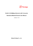
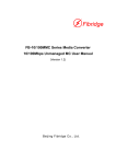
F4-51 10/100Mbps Ethernet over E1
Protocol Converter User Manual
(Version 1.0)
Beijing Fibridge Co., Ltd.
F4-51 User Manual V1.0
Contents
1.
Overview ....................................................................... 3
2.
Features ........................................................................ 3
3.
Application.................................................................... 4
3.1. Peer-to-Peer application with standalone .............. 4
3.2. Star-Topology with chassis and standalone........... 5
4.
Specification ................................................................. 5
4.1. E1 port................................................................... 5
4.2. Ethernet port.......................................................... 6
4.3. Power .................................................................... 6
4.4. Environment .......................................................... 6
4.5. Dimensions & Weight ............................................ 7
5.
Panel Instruction .......................................................... 7
5.1. Front Panel............................................................ 8
5.2. Back Panel .......................................................... 10
5.3. LED Description .................................................. 10
5.4. Ports’ Description ................................................ 13
5.5. Switches’ Description .......................................... 13
6.
Installation & Operation ............................................. 15
6.1. Installation Steps ................................................. 15
6.1.1.
Preparation .................................................... 15
6.1.2.
Connection..................................................... 16
- 1 -
F4-51 User Manual V1.0
6.1.3.
Power ON ...................................................... 17
6.2. Something Notice ................................................ 18
6.3. Faults & Solutions ............................................... 18
7.
6.3.1.
E1 LOS ON .................................................... 18
6.3.2.
E1 LOF ON .................................................... 18
Order Information....................................................... 19
- 2 -
F4-51 User Manual V1.0
1. Overview
F5-4511 Series F4-51 Converter is a high performance,
remote, self-learning Module Card Ethernet bridge. Its
compact size and low cost make it ideal for cost-sensitive
bridging applications or as a LAN extender over bit stream
type infrastructures. Its E1 data interface also provides an
economical digital access solution for E1 and Fractional E1
network Services, which can work at data rates of 64Kbps to
2048Kbps. User data is placed into the E1 frame, using only
the required number of timeslots. Timeslot assignment is
accomplished according to the Data Port speed and manual
setting of DIP switches. The main E1 link may be clocked
from the recovered receive clock or from an internal oscillator.
For easy to check the fault of network line, the device
provides loop selection, both local loop and remote loop.
2. Features
Hardware Function:
z
High performance bridge for 10/100MBase-T Ethernet
extension
z
Fully
compatible
with
IEEE
802.3
and
Ethernet
Standards
z
E1 channel: Full and Fabrication optional, 75/120ohm
optional
- 3 -
F4-51 User Manual V1.0
z
Ethernet
Port::
10Mbps,
Full/Half
Duplex
Mode
compatible
z
10/100MBase-T LAN Interface on RJ-45 connector and
MDI/MDI-X compatible
z
15000 frames per second filtering and forwarding rate
z
1000 MAC address LAN table, and automatic LAN table
learning and aging.
z
Standalone and 16 slots chassis optional
z
Power of Chassis: 2 Slots for slide in power supplier
module, AC or DC power supplier module, Redundant
Power supported
3. Application
3.1. Peer-to-Peer application with standalone
Figure1: Peer-to-peer topology
- 4 -
F4-51 User Manual V1.0
3.2. Star-Topology with chassis and standalone
Figure2: Star topology
Note: No matter which topology you use, the F4-51 protocol
converter should be used in-pairs. LAN transmit channel is
Ethernet, WAN channel is E1; this two transmit channels can’t
be exchanged.
4. Specification
4.1. E1 port
z Data rate: N×64Kbps, N=1~31
z Code type: HDB3
z Compliant with G.703, G.704, G.706, G.732
z 75Ω/ 120Ω Optional, auto-negotiation
z BNC (75Ω) / RJ45(120Ω)
z Filter: Compliant with ITU-T G.823
z Framed / Unframed optional
Table1: RJ45 connector (120Ω E1)
- 5 -
F4-51 User Manual V1.0
Pin
1
2
4
5
3,6
else
Function
RX+
RX-
TX-
TX+
GND
reserved
4.2. Ethernet port
z Standard:
IEEE802.3, 802.3u
z 10/100Mbps, Half/Full Duplex
z RJ45 Connector
z MDI/MDI-X compatible
z Number of Ports: 1
z Commendatory transmit distance is less than 100m
4.3. Power
z Power Input:
AC Power: 198V~242VAC, 50/60Hz;
DC Power: -48VDC
z Power Consumption:
<3W for each standalone or module
4.4. Environment
z Operating
Temperature: 0~+50℃
Relative Humidity: 0~90% (non-condensing)
z Storage
Temperature: -25~+70℃
Relative Humidity: 0~95% (non-condensing)
- 6 -
F4-51 User Manual V1.0
4.5. Dimensions & Weight
z Dimensions:
Standalone
252mm Width ×36mm Height ×135.5mm Depth (mm)
Module
25.3mm Width ×146mm Height ×219.5mm Depth (mm)
Chassis
19’ Width ×4UHeight ×340mm Depth (mm)
z Shipping Weight:
Standalone: 1.1Kg (approx.)
Module: 0.4Kg (approx.)
5. Panel Instruction
- 7 -
F4-51 User Manual V1.0
5.1. Front Panel
Standalone
Figure3: Standalone front panel
Note: Timeslot set switch has 32 pin in all, corresponding to
32 E1 timeslot. The detail is in Table 5.
- 8 -
F4-51 User Manual V1.0
Module
Figure 4: Module front panel
- 9 -
F4-51 User Manual V1.0
5.2. Back Panel
Standalone
Figure 5: Standalone back panel
Note: Console is optional. It can be fixed according to your
need.
5.3. LED Description
Standalone:
z
Table 2: Standalone front panel LED
ID
Color
PWR
G
LOOP
G
FDX
G
Status
Description
ON
Power supply OK
OFF
Power supply failed
ON
Local loop
OFF
No loop
ON
Ethernet work at full duplex status
OFF/
Ethernet work at half duplex status
Blink
CRC
R
ON
E1 frame CRC error
OFF
E1 frame no CRC error
- 10 -
F4-51 User Manual V1.0
LOS
LOF
AIS
RAL
R
R
R
R
ON
Local E1 link signal loss
OFF
E1 link signal OK
ON/
Local E1 synchronization loss
Blink
OFF
E1 link signal OK
ON
Local E1 link has AIS alarm
OFF
E1 link signal OK
ON
Remote E1 has LOS or LOF
OFF
Remote E1 link OK
Note: R: red; G: green; Y: yellow.
Table 3: Standalone back panel LED
ID
LINK/
ACT
100M
Color
Status
ON
G
Y
状态说明
Ethernet link OK
Blink
Ethernet receive or transmit data
OFF
Ethernet link failed
ON
Ethernet rate is 100M
OFF
Ethernet rate is 10M
- 11 -
F4-51 User Manual V1.0
Module:
z
Table 4: Module LED
ID
Color
PWR
G
LOOP
G
FDX
G
CRC
R
LOS
R
LOF
AIS
R
R
RAL
R
LINK/
G
ACT
Status
Description
ON
Power supply OK
OFF
Power supply failed
ON
Local loop
OFF
No loop
ON
Ethernet work at full duplex
status
OFF/
Blink
Ethernet work at half duplex
status
ON
E1 line has CRC error
OFF
No CRC error
ON
Local E1 link signal loss
OFF
E1 link signal OK
ON/
Local E1 synchronization loss
Blink
OFF
E1 link signal OK
ON
Local E1 link has AIS alarm
OFF
E1 link signal OK
ON
Remote E1 has LOS or LOF
OFF
Remote E1 link OK
ON
Ethernet link OK
Blink
Ethernet receive or transmit data
- 12 -
F4-51 User Manual V1.0
100M
Y
OFF
Ethernet link failed
ON
Ethernet rate is 100M
OFF
Ethernet rate is 10M
5.4. Ports’ Description
Table 5: Port description
Port
ID
Description
75Ω:IN, OUT
Unbalanced interface, BNC
connector,
E1
Ethernet
120Ω:120ohm
Balanced interface, RJ45
connector
ETHERNET
RJ45 connector
5.5. Switches’ Description
Table 6: Timeslot set
Pin
0~31
ON
OFF
Use this timeslot
Not use this timeslot
As factory default, pin “0” is ON, other timeslot pin is OFF. It’s
no framed E1 mode.
Note:
z
Standalone has timeslot switch indicate at shell, the sign
of module is “SW1~SW4”.
z
These timeslots can only be choose at E1 framed mode,
from left to right is 0~31 timeslot.
z
No framed E1 mode setting: Set timeslot pin”0” ON, then
other timeslot pins will be useless. E1 bandwidth is
- 13 -
F4-51 User Manual V1.0
2.048M.
z
Framed E1 mode setting: Set timeslot pin”0” OFF, please
be assured that at least one timeslot pin besides pin”0” is
ON. The bandwidth is N×64Kbps(N=1~31). At framed
mode, the bandwidth of two equipments working in pair is
the same.
Table 7: Mode set
PIN
1
TIM_MODE
2
BUFF_SEL
3
COUPLE
ON
OFF
Recovered Clock
Internal Oscillator
Small Buffer
Large Buffer
E1
Bandwidth
couple.
Local
bandwidth
E1
is
the
same with remote
No bandwidth couple
functions.
E1 bandwidth.
4
Local Loop
No Loop
Test SDRAM
No Test
6 DPX
Full Duplex Ethernet
Half Duplex Ethernet
7 SPD
100M Ethernet
10M Ethernet
LOOP_SEL
5
SDRAM_TEST
8
AN_ENA
Ethernet
negotiation
Auto
Constraint
Mode
Note:
z
As factory default, these 8 pins are all “OFF”.
- 14 -
Ethernet
F4-51 User Manual V1.0
z
If you change the Ethernet status via the switches, please
reset the F4-51 equipment then it can work at the new
Ethernet status.
z
Standalone has mode set switch sign at shell; the sign of
module is “SW5”.
6. Installation & Operation
6.1. Installation Steps
6.1.1. Preparation
z Electric iron, which is used to weld the BNC connectors to
E1 cable.
z E1 analyzer, which is used to test the E1 transmission line
z Make 75Ω E1 cable. There are two BNC connectors (for
75Ω E1) and one RJ45 plug (for 120Ω E1) in the package.
If you want to use 75Ω interface, take out the BNC
connectors, and weld them on the 75Ω E1 coaxial cable
(Figure 6).
- 15 -
F4-51 User Manual V1.0
Figure6: 75Ω BNC
z Make 120Ω E1 cable. If you use 120Ω interface, take out
RJ45 plug, and fix it on twister-pair cable (Figure 7). Table
1 is the detailed definition of 120Ω connector.
Figure 7: 120Ω RJ45
6.1.2. Connection
z Check the device and accessories according to Packing
List when open the package. If anything missing or
damaged, please contact us immediately.
z Take out the equipment; place it on neat table or the other
platform.
z Set dip switches according to your demand. Please don’t
set both the two equipment working in pairs at master
- 16 -
F4-51 User Manual V1.0
timing mode. The commendatory timing mode is one
working at master clock, the other is recovered clock.
z Connect the 10/100Base-T cable and E1 cables (Figure8)
to the interfaces. The 75Ω E1 line and the 120ΩE1 line
can’t be connected at one time.
Figure8: 75Ω E1 connection
z Connect power supply cable to the equipment. For the
modules, fix them in the chassis, and connect power
supply cable to the chassis.
6.1.3. Power ON
z If the equipment works normally, all the LED indicators are
off, except for “PWR”. When you connect Ethernet line, the
indicator “LINK/ACT” is on or blinks. “FDX” and “SPD” will
ON or OFF according to the Ethernet state and the
switches setting mode.
- 17 -
F4-51 User Manual V1.0
6.2. Something Notice
z Make sure the type of power supply is in accordance with
the equipment request.
z It is very important that equipments are connected to earth
rightly and firmly. Check the distributing of the power
supply and the connection to the earth.
z Please don’t set two F4-51 working in-pair both at “Internal
Oscillator” time-mode. In general, one is “Recovered
clock”, the other is “Internal Oscillator”. If you assured that
there is line clock in the E1 line, you can set F4-51
“Tim-mod” both at “Recovered clock”.
6.3. Faults & Solutions
6.3.1. E1 LOS ON
Check if the E1 “IN” and “OUT” are connected by contraries.
6.3.2. E1 LOF ON
Check if the two F4-51 equipments working in-pair are all
work
at
“framed
mode”
or
“unframed
mode”.
If
in
framed-mode, be sure that E1 timeslot of the two F4-51 is in
the same;Or there is code error in the E1 line.
- 18 -
F4-51 User Manual V1.0
7. Order Information
P/N
F4-51A
Description
10/100M Ethernet to E1converter, standalone,
220VAC power supply
F4-51D
10/100M Ethernet to E1converter, standalone,
-48VDC power supply
F4-51M
10/100M Ethernet to E1converter, Module card
FC-416
16 slot chassis, supply two powers
** We Reserve the right to vary descriptions and specifications
without notice due to Fibridge’s policy of continuous product
improvement**
- 19 -
F4-51 User Manual V1.0
Beijing Fibridge CO., LTD.
Address: A402, Power Creative Building, NO.1 Shangdi East
RD., Haidian District, Beijing
Tel: +86-10-58858988
Fax: +86-10-58858520
Email: [email protected]
Website: http://www.fibridge.com
- 20 -