1
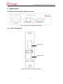
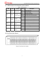
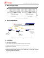
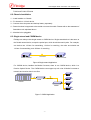
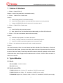
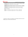
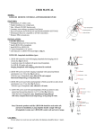
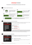
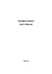
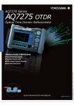
FB-10/100MMC Series Media Converter
10/100Mbps Unmanaged MC User Manual
(Version 1.2)
Beijing Fibridge Co., Ltd.
Unmanaged Media Converter User Manual V1.2
Table of Content
1.
Overview .........................................................................................................................2
2.
Features ..........................................................................................................................2
3.
Specification ...................................................................................................................2
3.1.
Ethernet Port ................................................................................................................2
3.2.
Optical Port...................................................................................................................3
3.3.
Environment .................................................................................................................3
3.4.
Size...............................................................................................................................3
3.5.
Power ...........................................................................................................................3
4.
Appearance.....................................................................................................................4
4.1.
Panel of the Standalone Media Converter ....................................................................4
4.2.
Panel of the Module......................................................................................................4
4.3.
LED Description of the Standalone and the Module .....................................................5
4.4.
Front Panel of the Chassis ...........................................................................................5
4.5.
Back Panel of the Chassis............................................................................................6
5.
Typical Applications.......................................................................................................6
6.
Installation ......................................................................................................................6
6.1.
Standalone Installation..................................................................................................6
6.2.
Chassis Installation.......................................................................................................7
6.3.
Single-strand and CWDM device..................................................................................7
7.
Failures & Solutions.......................................................................................................8
8.
Typical Module: ..............................................................................................................8
8.1.
Model:...........................................................................................................................8
8.2.
Part Number (P/N) ........................................................................................................8
-1-
Unmanaged Media Converter User Manual V1.2
1. Overview
With the rich experience of studying US broadband access products in the past few years and
fully assimilated with the product superiority of world-famous manufactures, Fibridge develops a
series of Fiber Media Converter which is high-performance, cost effective and flexible solutions for
a wide range of applications in the realm of LAN campus network, outside plant and MAN
application.
Products package covers both standard 19 chassis and stand alone with internal power
supply that significantly increases the reliability over competitive products. Exchange chips not
only support 802.1QVLAN TGA, SPANNING TREE, but auto sensing 10M/100M, half/full duplex.
Fibridge Media Converter series include double-strand and single-strand converters, as well as
managed Media converter to meet your possible needs. This manual provides instruction of
unmanaged Media Converters only.
2. Features
z
Fully compatible with IEEE 802.3, IEEE802.3u and IEEE802.3x
z
Support 10Base-T, 100Base-TX, 100Base-FX
z
Support Half/Full-Duplex, Full-Duplex, Half-Duplex
z
Support 802.1q VLAN TAG、Spanning Tree
z
One single fiber strand meet client’s possible needs
z
Up to 120Km distance on single-mode fiber
z
High performance and auto sensing exchange chip, which have full functionality of
transferring and exchanging, guarantee the safety and stability of data transfer.
z
MDI/MDI-X auto sensing
z
Far end fault pattern received display
z
CRC automatic fault checkout and correction
z
Internal power supply, including AC220V or DC-48V
z
Two types optional: stand-alone unit and Modular Chassis
3. Specification
3.1. Ethernet Port
1) Standard:IEEE 802.3、IEEE802.3u and IEEE802.3x
2) Available in 10Mbps, 100Mbps and 10/100 auto sensing
3) Auto sensing Full-Duplex and Half-Duplex operation
-2-
Unmanaged Media Converter User Manual V1.2
4) Connectors:RJ-45 Connector
5) Auto MDI/MDI-X connector cable selection
3.2. Optical Port
1) Adopt standard 1×9 pin optical transceiver module
2) Wavelength:850nm, 1310nm on multi-mode, 1310nm, 1550nm on single-mode
3) Transfer Distance:up to 120Km
4) Fiber core:8.3µm, 8.7µm, 9µm and 10µm on single mode fiber, 50µm, 62.5µm and 100µm on
multi-mode fiber
5) connectors:SC/ST/FC at optional
6) Fiber Power Budget
Wavelength
(nm)
Connector
Emit Power
(dBm)
Sensitivity
(dBm)
Saturation
(dBm)
Max Dist.
(Km)
Loss
(dBm/Km)
MM850
SC/ST
-14 ~ -18.5
-31~ -34
-14
2
3
MM1310
SC/ST
-14 ~ -18.5
-31~ -34
-14
5
2
SM1310
SC/ST/FC
-6 ~ -15
-3
40
0.4
SM1310
SC/ST/FC
3 ~ -3
-3
80
0.4
1550 DFB
SC/ST/FC
3 ~ -3
-3
120
0.25
Better than
-34
Better than
-36
Better than
-36
3.3. Environment
1) working environment :
Temperature:5℃~40℃;
Humidity:30%~90%(25℃);
Atmosphere pressure:86kPa~106 kPa.
2) Store and transportation enviroment:
Temperature:-20℃~60℃;
Humidity:20%~90%(25℃);
Atmosphere pressure:86kPa~106 kPa。
3.4. Size
Device Size:132mm (width) × 122mm (depth) × 36mm (height)
Chassis Size:440mm (width) ×250mm (depth) × 125mm (height) (19’ Width, 2.5U Height)
3.5. Power
Power Supply:100-240VAC, 50/60Hz
or
-48VDC
Consumption: <2W
-3-
Unmanaged Media Converter User Manual V1.2
4. Appearance
4.1. Panel of the Standalone Media Converter
Ethernet Port
Optical Port
Figure1 Panel of the unmanaged standalone
4.2. Panel of the Module
Optical Port
Ethernet Port
Figure2 Panel of the unmanaged Module
-4-
Unmanaged Media Converter User Manual V1.2
4.3. LED Description of the Standalone and the Module
Table 1 LED Description
LED
PWR
Color
Green
Function
Description
ON
Power Supply OK
OFF
No Power Supply
ON
Twist-pair port linked
BLINK
Twist-pair port is transferring data
OFF
Twist-pair not linked
ON
Optical port linked
BLINK
Optical port is transferring data
OFF
Optical port not linked
ON
The device’s rate is 100M
OFF
The device’s rate is 10M
BLINK
Receive FEF
pattern received
OFF
Not receive FEF
Fiber port signal
ON
Fiber signal detected
detect
OFF
Fiber unplugged
Power Status
Twist-pair
Tlink
Status
port
Yellow
Link/Act Status
Optical
Flink
port
Yellow
Link/Act Status
Twist-pair
100M
port
Green
speed
FEF
SD
Red
Green
Far
end
fault
4.4. Front Panel of the Chassis
Figure 3 Front Panel of the Chassis
-5-
Unmanaged Media Converter User Manual V1.2
4.5. Back Panel of the Chassis
Power Supply
Power Supply
Figure 4 Back Panel of the Chassis
5. Typical Applications
16
Network Switch
UTP5
16x Chassis
Fiber
Fiber
Fiber
Media Converter
Media Converter
Media Converter
User16
User1
User2
Figure 5 Typical Application Topology of the Media Converter
6. Installation
6.1. Standalone Installation
1) Small, flexible design allows for installation anywhere space is limited
2) Connect power after fiber and twist pair line is correctly connected
3) TLINK LED is on after reset
4) If circuit line correctly connected, PWR, TLINK and FLINK LED is on after reset checkout
5) If equipment words normally the status of LED is always ON. If it works under 100 Mbps
Ethernet, the 100M LED is always ON
6) If all stipulated above work normally, circuit test could be carried out then During data transfer,
-6-
Unmanaged Media Converter User Manual V1.2
TLINK and FLINK LED blink
6.2. Chassis Installation
1) Install module on Chassis
2) Fix chassis on 19-inch device
3) Connect the main power and backup battery separately
4) Reset checkout is supposed to be carried out on each module. Please refer to the statement of
Standalone unit stipulated above
5) Modules is hot pluggable
6.3. Single-strand and CWDM device
Fibridge can also provide single-strand or CWDM device. Single-strand device is the same to
the Double-strand device, except the optical port, which should be used in pairs. For example,
one device use 1510nm for transmitting, 1310nm for receiving, the other end should use
1310nm for transmitting, and 1550nm for receiving.
Media Converter
One Fiber
Media Converter
Figure 6 Single-strand Application
For CWDM device, besides the Media Converter, there is one CWDM device, which is a
Passive Optical Device. The CWDM device can support up to 8 units of Media Converter to
transmit and receive data in one fiber.
1
2
One Fiber
CWDM
Chassis
3
CWDM
8
Media Converter
Figure 7 CWDM Application
-7-
Unmanaged Media Converter User Manual V1.2
7. Failures & Solutions
1) Failure:Power LED is off
Solution:check if the power line is connected correctly
2) Failure:TLINK LED is off after reset
Solution:
a)
check if twist pair line is connected correctly
b)
check if the Ethernet device connected with the converter is running normally
c)
change the MDI/MDI-X switch’s status on the converter panel
3) Failure:FLINK LED is off after reset
Solution:
a)
check if the fiber is connected correctly
b)
Note:either RX or TX of the fiber line work abnormally, the Flink LED will turn off
4) Failure:LED is at normal status, data transfer abnormally
Solution:
a)
check the output power of converter optical port
b)
be sure no single mode fiber connected with multimode equipment
c)
check if it is used in pairs when single-strand converter is used
5) Failure:the devices are shutdown after work normally some time
Solution:
It is usually caused by Switch. In normal status, the Switch will take Cyclic Redundancy Check and
throw away the faulty data. However, some faulty data could not be inspected and thus could not
be sent out or thrown away. These faulty data will be stored in the buffer gradually until the switch
is filled with them, which brings about the abnormal shut of Switch. Reset of either converter or
Switch is the solution.
8. Typical Module:
8.1. Model:
FB-10/100MMC Media Converter
FB-CHS Chassis
8.2. Part Number (P/N)
F1-M32CA Multimode, 1310nm, SC, standalone, 220VAC power supply
F1-M31CD Multimode, 850nm, SC, standalone, -48VDC power supply
F1-S3042CA Single mode, Distance: 40km, 1310nm, SC, standalone, 220VAC power supply
-8-
Unmanaged Media Converter User Manual V1.2
F1-S3082CA Single mode, Distance: 80km, 1310nm, SC, standalone, 220VAC power supply
F1-S3042TM Single mode, Distance: 40km, 1310nm, ST, Module
F1-W3042CA Single Strand Single mode, Distance: 40km, transmit 1310nm, SC, Standalone
F1-W3043CA Single Strand Single mode, Distance: 40km, transmit 1550nm, SC, Standalone
F1-W3042CM Single Strand Single mode, Distance: 40km, transmit 1310nm, Module
F1-W3043CM Single Strand Single mode, Distance: 40km, transmit 1550nm, Module
FC-216 16-slot Chassis
FP-2100A
16-slot chassis power supply module, AC 220V input, 100Watt output
FP-2100D
16-slot chassis power supply module, DC -48V input, 100Watt output
** We Reserve the right to vary descriptions and specifications without notice due to
Fibridge’s policy of continuous product improvement**
-9-