1
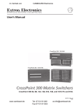
TPX 88 and TPX 88 A
Twisted Pair Matrix Switcher
Twisted Pair Matrix Switcher with Local Audio Outputs
68-733-01 Rev. C
12 05
Precautions
Safety Instructions • English
Warning
This symbol is intended to alert the user of important operating and maintenance
(servicing) instructions in the literature provided with the equipment.
Power sources • This equipment should be operated only from the power source indicated on the product. This
equipment is intended to be used with a main power system with a grounded (neutral) conductor. The
third (grounding) pin is a safety feature, do not attempt to bypass or disable it.
This symbol is intended to alert the user of the presence of uninsulated dangerous
voltage within the product’s enclosure that may present a risk of electric shock.
Power disconnection • To remove power from the equipment safely, remove all power cords from the rear of
the equipment, or the desktop power module (if detachable), or from the power source receptacle (wall
plug).
Caution
Read Instructions • Read and understand all safety and operating instructions before using the equipment.
Retain Instructions • The safety instructions should be kept for future reference.
Follow Warnings • Follow all warnings and instructions marked on the equipment or in the user
information.
Avoid Attachments • Do not use tools or attachments that are not recommended by the equipment
manufacturer because they may be hazardous.
Consignes de Sécurité • Français
Power cord protection • Power cords should be routed so that they are not likely to be stepped on or pinched by
items placed upon or against them.
Servicing • Refer all servicing to qualified service personnel. There are no user-serviceable parts inside. To
prevent the risk of shock, do not attempt to service this equipment yourself because opening or removing
covers may expose you to dangerous voltage or other hazards.
Slots and openings • If the equipment has slots or holes in the enclosure, these are provided to prevent
overheating of sensitive components inside. These openings must never be blocked by other objects.
Lithium battery • There is a danger of explosion if battery is incorrectly replaced. Replace it only with the
same or equivalent type recommended by the manufacturer. Dispose of used batteries according to the
manufacturer’s instructions.
Avertissement
Ce symbole sert à avertir l’utilisateur que la documentation fournie avec le matériel
contient des instructions importantes concernant l’exploitation et la maintenance
(réparation).
Alimentations• Ne faire fonctionner ce matériel qu’avec la source d’alimentation indiquée sur l’appareil. Ce
matériel doit être utilisé avec une alimentation principale comportant un fil de terre (neutre). Le troisième
contact (de mise à la terre) constitue un dispositif de sécurité : n’essayez pas de la contourner ni de la
désactiver.
Ce symbole sert à avertir l’utilisateur de la présence dans le boîtier de l’appareil
de tensions dangereuses non isolées posant des risques d’électrocution.
Déconnexion de l’alimentation• Pour mettre le matériel hors tension sans danger, déconnectez tous les cordons
d’alimentation de l’arrière de l’appareil ou du module d’alimentation de bureau (s’il est amovible) ou
encore de la prise secteur.
Attention
Lire les instructions• Prendre connaissance de toutes les consignes de sécurité et d’exploitation avant
d’utiliser le matériel.
Conserver les instructions• Ranger les consignes de sécurité afin de pouvoir les consulter à l’avenir.
Respecter les avertissements • Observer tous les avertissements et consignes marqués sur le matériel ou
présentés dans la documentation utilisateur.
Eviter les pièces de fixation • Ne pas utiliser de pièces de fixation ni d’outils non recommandés par le
fabricant du matériel car cela risquerait de poser certains dangers.
Protection du cordon d’alimentation • Acheminer les cordons d’alimentation de manière à ce que personne ne
risque de marcher dessus et à ce qu’ils ne soient pas écrasés ou pincés par des objets.
Réparation-maintenance • Faire exécuter toutes les interventions de réparation-maintenance par un technicien
qualifié. Aucun des éléments internes ne peut être réparé par l’utilisateur. Afin d’éviter tout danger
d’électrocution, l’utilisateur ne doit pas essayer de procéder lui-même à ces opérations car l’ouverture ou le
retrait des couvercles risquent de l’exposer à de hautes tensions et autres dangers.
Fentes et orifices • Si le boîtier de l’appareil comporte des fentes ou des orifices, ceux-ci servent à empêcher
les composants internes sensibles de surchauffer. Ces ouvertures ne doivent jamais être bloquées par des
objets.
Lithium Batterie • Il a danger d’explosion s’ll y a remplacment incorrect de la batterie. Remplacer uniquement
avec une batterie du meme type ou d’un ype equivalent recommande par le constructeur. Mettre au reut les
batteries usagees conformement aux instructions du fabricant.
Sicherheitsanleitungen • Deutsch
Stromquellen • Dieses Gerät sollte nur über die auf dem Produkt angegebene Stromquelle betrieben werden.
Dieses Gerät wurde für eine Verwendung mit einer Hauptstromleitung mit einem geerdeten (neutralen)
Leiter konzipiert. Der dritte Kontakt ist für einen Erdanschluß, und stellt eine Sicherheitsfunktion dar. Diese
sollte nicht umgangen oder außer Betrieb gesetzt werden.
Dieses Symbol soll den Benutzer darauf aufmerksam machen, daß im Inneren des
Gehäuses dieses Produktes gefährliche Spannungen, die nicht isoliert sind und
die einen elektrischen Schock verursachen können, herrschen.
Stromunterbrechung • Um das Gerät auf sichere Weise vom Netz zu trennen, sollten Sie alle Netzkabel
aus der Rückseite des Gerätes, aus der externen Stomversorgung (falls dies möglich ist) oder aus der
Wandsteckdose ziehen.
Achtung
Lesen der Anleitungen • Bevor Sie das Gerät zum ersten Mal verwenden, sollten Sie alle Sicherheits-und
Bedienungsanleitungen genau durchlesen und verstehen.
Aufbewahren der Anleitungen • Die Hinweise zur elektrischen Sicherheit des Produktes sollten Sie
aufbewahren, damit Sie im Bedarfsfall darauf zurückgreifen können.
Befolgen der Warnhinweise • Befolgen Sie alle Warnhinweise und Anleitungen auf dem Gerät oder in der
Benutzerdokumentation.
Keine Zusatzgeräte • Verwenden Sie keine Werkzeuge oder Zusatzgeräte, die nicht ausdrücklich vom
Hersteller empfohlen wurden, da diese eine Gefahrenquelle darstellen können.
Instrucciones de seguridad • Español
Schutz des Netzkabels • Netzkabel sollten stets so verlegt werden, daß sie nicht im Weg liegen und niemand
darauf treten kann oder Objekte darauf- oder unmittelbar dagegengestellt werden können.
Wartung • Alle Wartungsmaßnahmen sollten nur von qualifiziertem Servicepersonal durchgeführt werden.
Die internen Komponenten des Gerätes sind wartungsfrei. Zur Vermeidung eines elektrischen Schocks
versuchen Sie in keinem Fall, dieses Gerät selbst öffnen, da beim Entfernen der Abdeckungen die Gefahr
eines elektrischen Schlags und/oder andere Gefahren bestehen.
Schlitze und Öffnungen • Wenn das Gerät Schlitze oder Löcher im Gehäuse aufweist, dienen diese zur
Vermeidung einer Überhitzung der empfindlichen Teile im Inneren. Diese Öffnungen dürfen niemals von
anderen Objekten blockiert werden.
Litium-Batterie • Explosionsgefahr, falls die Batterie nicht richtig ersetzt wird. Ersetzen Sie verbrauchte
Batterien nur durch den gleichen oder einen vergleichbaren Batterietyp, der auch vom Hersteller
empfohlen wird. Entsorgen Sie verbrauchte Batterien bitte gemäß den Herstelleranweisungen.
Advertencia
Este símbolo se utiliza para advertir al usuario sobre instrucciones importantes
de operación y mantenimiento (o cambio de partes) que se desean destacar en el
contenido de la documentación suministrada con los equipos.
Alimentación eléctrica • Este equipo debe conectarse únicamente a la fuente/tipo de alimentación eléctrica
indicada en el mismo. La alimentación eléctrica de este equipo debe provenir de un sistema de distribución
general con conductor neutro a tierra. La tercera pata (puesta a tierra) es una medida de seguridad, no
puentearia ni eliminaria.
Este símbolo se utiliza para advertir al usuario sobre la presencia de elementos con
voltaje peligroso sin protección aislante, que puedan encontrarse dentro de la caja
o alojamiento del producto, y que puedan representar riesgo de electrocución.
Desconexión de alimentación eléctrica • Para desconectar con seguridad la acometida de alimentación eléctrica
al equipo, desenchufar todos los cables de alimentación en el panel trasero del equipo, o desenchufar el
módulo de alimentación (si fuera independiente), o desenchufar el cable del receptáculo de la pared.
Precaucion
Leer las instrucciones • Leer y analizar todas las instrucciones de operación y seguridad, antes de usar el
equipo.
Conservar las instrucciones • Conservar las instrucciones de seguridad para futura consulta.
Obedecer las advertencias • Todas las advertencias e instrucciones marcadas en el equipo o en la
documentación del usuario, deben ser obedecidas.
Evitar el uso de accesorios • No usar herramientas o accesorios que no sean especificamente recomendados
por el fabricante, ya que podrian implicar riesgos.
ᅝܼ乏ⶹ•Ё᭛
䖭Ͼヺোᦤ⼎⫼᠋䆹䆒⫼᠋ݠЁ᳝䞡㽕ⱘ᪡㓈ᡸ䇈ᯢDŽ
䖭Ͼヺো䄺ਞ⫼᠋䆹䆒ᴎݙ᳝ᲈ䴆ⱘॅ䰽⬉य़ˈ᳝㾺⬉ॅ䰽DŽ
⊼ᛣ
Vorsicht
Dieses Symbol soll dem Benutzer in der im Lieferumfang enthaltenen
Dokumentation besonders wichtige Hinweise zur Bedienung und Wartung
(Instandhaltung) geben.
䯙䇏䇈ᯢк• 䑩ㅸỀ䑩嬦嫿⡈⼆枼敆嬼䍇夤ㆁ㙊⫊₩⏍Ề䑩嬵㕏ɿ
ֱᄬ䇈ᯢк• 䑩ㅸⷕ⪙⫊₩嬵㕏ᶧḦ⡈⭇㚦Ề䑩ɿ
䙉ᅜ䄺ਞ• 䑩ㅸⷕ徶⫉ᷨ␂⏍䑩ㅸ㉈⊘ᵋ䗅ㆁ㙊⫊₩⏍㐎ẝ嬵㕏ɿ
䙓ܡ䗑ࡴ• ᵎ壂Ề䑩嬦ᷨ␂⋃⒇㯢㙊㋩劑䗅₸ㅗ弾⇡嫿⡈澤Ḧ忀₎⊲斪ɿ
Protección del cables de alimentación • Los cables de alimentación eléctrica se deben instalar en lugares donde
no sean pisados ni apretados por objetos que se puedan apoyar sobre ellos.
Reparaciones/mantenimiento • Solicitar siempre los servicios técnicos de personal calificado. En el interior no
hay partes a las que el usuario deba acceder. Para evitar riesgo de electrocución, no intentar personalmente
la reparación/mantenimiento de este equipo, ya que al abrir o extraer las tapas puede quedar expuesto a
voltajes peligrosos u otros riesgos.
Ranuras y aberturas • Si el equipo posee ranuras o orificios en su caja/alojamiento, es para evitar el
sobrecalientamiento de componentes internos sensibles. Estas aberturas nunca se deben obstruir con otros
objetos.
Batería de litio • Existe riesgo de explosión si esta batería se coloca en la posición incorrecta. Cambiar esta
batería únicamente con el mismo tipo (o su equivalente) recomendado por el fabricante. Desachar las
baterías usadas siguiendo las instrucciones del fabricante.
䄺ਞ
⬉⑤• 嬦嫿⡈⌫倾Ề䑩ᷨ␂ᵋ㝈㕏䗅䑶㷑ɿ嫿⡈⼆枼Ề䑩㙊♱一䗅Ờ䑶䰼丠Ờ䑶ɿ䩭ᵊ㚢一
澠♱一澡㕰⫊₩嫿㓾澤ᵎ倾ᵎ䑩ㅗ崴弈ɿ
ᢨᥝ⬉⑤• ᵻ⫊₩♱ḏ嫿⡈㈕㋊䑶㷑澤嬸㈕㋊ㆁ㙊嫿⡈⍏ㅗ㞍暣䑶㷑䗅䑶㷑一澤ㅗḼẖ㋦ⅱⵃ
䑶䰼丠䗅䑶㷑一ɿ
⬉⑤㒓ֱᡸ• ⣦Ⓟⵄ一澤忀₎埬嵪嵐澤ㅗ愎䆪㉥⋌ɿ
㓈ᡸ•ㆁ㙊丵Ἧ⼆枼䑲嫥嬂䗅丵Ἧ᷻⎙弜垍ɿ嫿⡈怩㯢㙊䑩ㅸ⌰Ḧ㘵㊣䗅昷ḷɿᵻ忀₎℻
䋱大䑶⊲斪ᵎ壂儫ⴲ嬖☿㆔⹁嫿⡈䘗⪑丵Ἧ嬦嫿⡈ɿ
䗮亢ᄨ• 㙊ᷜ嫿⡈㙻⠴ᵋ㙊彛栏㤾ㅗ⪕澤⫄ḭ㕰䑩㚦敳㪣㙻㒐だ₄ḷ弈䀮ɿᵎ壂䑩Ḽẖᵝ
壀㉢Ẑ彛栏⪕ɿ
䫖⬉∴• ᵎ㪤䞯䗅㘵㊣䑶㮡ṛ㙊䅇㿹䗅⊲斪ɿ⼆枼Ề䑩ᵏ⋃⫷㋩劑䗅䘹⍍ㅗ䘹弒⛌⌸䗅䑶㮡ɿ
㉊䂨䑠ᷨ⋃䗅⸻嫯⡅䍇ⷠ⹄䑶㮡ɿ
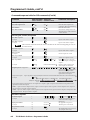
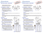
Quick Start — TPX Matrix Switchers
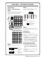
Installation
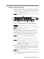
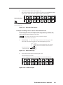
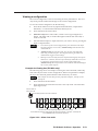
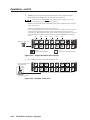
Step 4
Cable the switcher for twisted pair input and
output. See Termination of TP cable in chapter 2,
Installation, to properly terminate the RJ-45
connectors.
Side
Clip Down
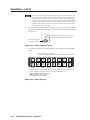
TP/VTT transmitters and receivers
12345678
568 A
Pin color
2 Green
Whiteorange
Orange
Whiteorange
4 Blue
Whitegreen
Blue
Whiteblue
Whitegreen
1
Video+
Video-
Audio+
N/C
Step 5
N/C
Set the rear panel Remote DIP switches.
Whiteblue
Green-
N/C
6* Orange Green
5
Audio-
N/C
Whitebrown
Whitebrown
Blue/
H. sync+
Audio+
8 Brown
Brown
Blue/
H. sync-
Audio-
7
RJ-45
connector
Red/
V. sync+
Red/
V. sync-
Video/
audio
Pin RS-232 Function
RS-422 Function
Gnd Gnd Signal ground Gnd Signal ground
TX- Transmit data (-)
TX— Not used
TX+ TX+ Transmit data TX+ Transmit data (+)
RX- Receive data (-)
RX— Not used
RX+ Receive data (+)
RX+ RX+ Receive data
Green+
3*
12345678
RGBHV/
audio
568 B
color
GND
TXTX +
RX RX +
If desired, connect a control system or computer
to the Remote (RS-232/RS-422) port.
Step 1 — Turn off power
Step 2
RS-232
RS-422
All switches up
for RS-232. (Default.)
Switches 1 & 2 down,
3 up for RS-422.
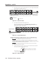
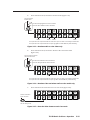
* The TPX 88 A switches pair 3 and 6.
The TPX 88 does not switch pair 3 and 6.
Twisted
Pairs
1&2 3&6 4&5
7&8
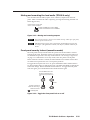
Audio or serial data from an RGB video MTP
is incompatible with both TPX models.
They cannot be switched.
NOTE If you are using Enhanced Skew-Free™ A/V cable,
use the TIA/EIA T 568A standard only.
Step 6
Plug the switcher and input and output devices
into a grounded AC source, and turn on the input
and output devices.
MTP transmitters and receivers
568 A
Pin Color
568 B
Color
Video
MTP
S-video
MTP
RGB video
MTP
1 White- Whitegreen orange Video + Luma (Y) +
Red/
V. Sync +
2 Green
Red/
V. Sync –
3*
White- WhiteNONE
orange green
Mono audio +
or RS-232 +
(MTP 15HD
only)
Chroma (C)
& audio left + Green +
White- White- Audio
blue
blue
left –
Chroma (C)
& audio left – Green –
Blue
NONE
Mono audio –
or RS-232 –
(MTP 15HD
only)
White- White- Audio
brown brown right +
Audio right+
Blue/
H. Sync +
Audio
right –
Audio right –
Blue
H. Sync –
6* Orange Green NONE
7
NONE
Audio
left +
4 Blue
5
Orange Video – Luma (Y) –
8 Brown Brown
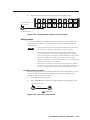
Step 3
TPX 88 A: Cable the switcher for stereo audio
output.
Tip
See caution
Sleeve
Tip
See caution
Unbalanced Output
Tip
Ring
Sleeve (s)
Tip
Ring
Balanced Output
CAUTION Connect the
sleeve to ground.
Connecting the
sleeve to a
negative (-)
terminal will
damage the audio
output circuits.
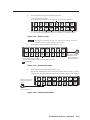
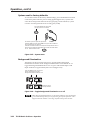
Definitions
Tie — An input-to-output connection.
Set of ties — An input tied to 2 or more outputs.
Configuration — One or more ties or sets of ties.
Current configuration — The currently active
configuration (also called configuration 0).
Global preset — A configuration that has been
stored. One preset can be assigned to each
input button. When a preset is retrieved from
memory, it becomes the current configuration.
Front Panel Controls
Input and output buttons and LEDs select and
identify inputs and outputs. Input buttons
also select presets. On the TPX 88 A, the
input and output LEDs also display the audio
levels.
Enter button saves changes when you change the
configuration.
Preset button saves a configuration as a preset or
recalls a previously-defined preset.
TPX 88 Matrix Switcher Quick Start
QS-1
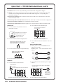
Quick Start — TPX 88 Matrix Switchers, cont’d
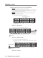
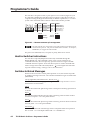
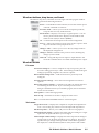
View button selects a view-only mode that prevents inadvertent configuration changes.
Esc button cancels selections in progress and resets the front panel LEDs. The Esc button does not
reset the current configuration, the Video and Audio LEDs, any presets, or any audio gain/
attenuation settings.
(TPX 88 A only) I/O button selects/deselects video and/or audio. The I/O button also selects the
audio level adjust mode.
(TPX 88 A only) Video and audio LEDs indicate that video and/or audio is selected for configuration.
(TPX 88 A only) Mute All button mutes and unmutes all audio outputs.
(TPX 88 A only) Volume knob adjusts the input level or output volume in audio level adjust mode.
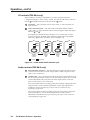
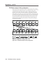
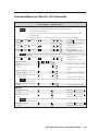
2. Press and release the desired input.
Create a tie
1. Press and release the I/O button to select
audio and/or video.
Press and release an input button.
The button lights.
I
N
P
U
T
I/O
VIDEO
AUDIO
Lights green when video is selected.
Lights red when audio is selected.
O
U
T
P
U
T
Press the button to cycle
through the selections.
2
2
The buttons for all tied outputs light.
The buttons for all untied outputs are unlit.
2. Press and release the desired input button.
Amber indicates video and audio (audio follow).
Green indicates video only (audio breakaway).
Red indicates audio only (audio breakaway)
1
1
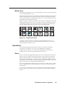
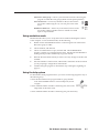
3. Press and release the View button to exit view
mode.
Save or recall a preset
1. Save a preset — Press and hold the Preset
button for 2 seconds.
5
Recall a preset — Press and release the Preset
button.
3. Press and release the desired output button(s).
Amber indicates video and audio tie.
Green indicates video tie.
Red indicates audio tie.
Save a
preset
2 seconds
PRESET
3
4
PRESET
Press and hold.
8
Preset LED blinks.
Recall a
preset
4. Press and release the Enter button.
PRESET
PRESET
Press and release.
View ties
1. Press and release the View button.
2. Press and release the desired input or output
button.
Press the button to
select view mode.
Press and release the input 1 button to select preset 1.
The button blinks.
The View LED lights when view mode is selected.
VIEW
I
N
P
U
T
O
U
T
P
U
T
1
1
2
2
The buttons for all untied outputs light until you select an input.
QS-2
Preset LED lights.
TPX 88 Matrix Switchers Quick Start
Preset 2
I
N
P
U
T
O
U
T
P
U
T
1
1
Preset 9
Preset 3
2
2
Preset 10 Preset 11
ENTER
The Enter button
blinks to indicate
the need to save or
recall the preset.
3. Press and release the Enter button.
Table of Contents
Chapter 1 • Introduction ....................................................................................................... 1-1
About the TPX 88 Manual ............................................................................................... 1-2
About the TP A/V System ................................................................................................ 1-2
TP cable advantages .......................................................................................................... 1-2
Transmission distances ....................................................................................................... 1-5
About Both TPX Switcher models .............................................................................. 1-6
About the TPX 88 A Switchers ..................................................................................... 1-7
Features ................................................................................................................................... 1-8
Chapter 2 • Installation .......................................................................................................... 2-1
Mounting the Switcher .................................................................................................... 2-2
Cabling and Rear Panel Views ...................................................................................... 2-3
Termination of TP cable ..................................................................................................... 2-4
Cable testing ................................................................................................................ 2-5
Equalizing pair skew with Skew Equalizers .................................................................. 2-6
Equalizing pair skew with skew compensation cables .................................................. 2-6
Audio outputs connectors (TPX 88 A only) ...................................................................... 2-7
Remote port configuration ............................................................................................... 2-8
Chapter 3 • Operation ............................................................................................................. 3-1
Front Panel Controls and Indicators ......................................................................... 3-2
Definitions .......................................................................................................................... 3-2
Input and output buttons ................................................................................................. 3-2
Control buttons .................................................................................................................. 3-3
I/O controls (TPX 88 A only) .............................................................................................. 3-4
Audio controls (TPX 88 A only) ......................................................................................... 3-4
Button icons ....................................................................................................................... 3-5
Operations .............................................................................................................................. 3-5
Power ................................................................................................................................. 3-5
I/O grouping ....................................................................................................................... 3-6
Creating a configuration ................................................................................................... 3-7
Example 1: Creating a set of video and audio ties ........................................................ 3-8
Example 2: Adding a tie to a set of video and audio ties ............................................. 3-9
Example 3a: Removing an audio tie from a set of ties (TPX 88 A only) ...................... 3-10
Example 3b: Removing a tie from a set of ties (TPX 88 only) ...................................... 3-12
Viewing a configuration ................................................................................................. 3-13
Example 4a: Viewing ties (TPX 88 A only) ................................................................... 3-13
Example 4b: Viewing ties (TPX 88 only) ...................................................................... 3-16
Using presets .................................................................................................................... 3-17
Example 5: Saving a preset ......................................................................................... 3-17
Example 6: Recalling a preset ..................................................................................... 3-18
TPX 88 Matrix Switchers • Table of Contents
i
Table of Contents, cont’d
Viewing and adjusting the input audio level (TPX 88 A only) ...................................... 3-20
Example 7: Viewing and adjusting an input audio level ............................................. 3-20
Viewing and adjusting the output volume (TPX 88 A only) .......................................... 3-22
Example 8: Viewing and adjusting an output volume level ....................................... 3-23
Muting and unmuting the local audio (TPX 88 A only) ................................................ 3-25
Front panel security lockout (executive mode) .............................................................. 3-25
System reset to factory defaults ..................................................................................... 3-26
Background illumination ................................................................................................. 3-26
Troubleshooting ................................................................................................................ 3-27
Worksheets .......................................................................................................................... 3-27
Worksheet example 1: System equipment .................................................................... 3-27
Worksheet example 2: Daily configuration ................................................................... 3-28
Worksheet example 3: Test configuration ..................................................................... 3-29
Configuration worksheet ................................................................................................ 3-31
Chapter 4 • Programmer’s Guide ..................................................................................... 4-1
Host-to-Switcher Instructions ....................................................................................... 4-2
Switcher-Initiated Messages ......................................................................................... 4-2
Switcher Error Responses ............................................................................................... 4-3
Using the Command/Response Table ........................................................................ 4-4
Symbol definitions ............................................................................................................. 4-4
Command/Response Table for SIS Commands ..................................................... 4-5
Chapter 5 • Matrix Software .............................................................................................. 5-1
Matrix Switchers Control Program ............................................................................ 5-2
Installing the software ...................................................................................................... 5-2
Using the software ............................................................................................................ 5-2
Firmware upgrade ............................................................................................................. 5-4
Windows buttons, drop boxes, and trash ........................................................................ 5-5
Windows menus ................................................................................................................. 5-5
File menu ...................................................................................................................... 5-5
Tools menu ................................................................................................................... 5-5
Preferences menu ......................................................................................................... 5-6
Using emulation mode ...................................................................................................... 5-7
Using the help system ........................................................................................................ 5-7
Button Label Generator ................................................................................................... 5-8
Using the software ............................................................................................................ 5-8
ii
TPX 88 Matrix Switchers • Table of Contents
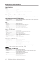
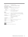
Appendix A • Reference Information .......................................................................... A-1
Specifications ....................................................................................................................... A-2
Part Numbers ....................................................................................................................... A-4
Twisted Pair Matrix Switcher part numbers .................................................................... A-4
Optional accessories ......................................................................................................... A-4
Cables ................................................................................................................................ A-4
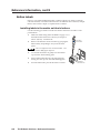
Button Labels ....................................................................................................................... A-6
Installing labels in the matrix switcher’s buttons ............................................................ A-6
Button label blanks ........................................................................................................... A-7
All trademarks mentioned in this manual are the properties of their respective owners.
68-733-01 Rev. C
12 05
TPX 88 Matrix Switchers • Table of Contents
iii
Table of Contents, cont’d
iv
TPX 88 Matrix Switchers • Table of Contents
TPX 88 Twisted Pair Matrix Switchers
1
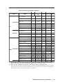
Chapter One
Introduction
About the TPX 88 Manual
About the TP A/V System
About Both TPX Switcher Models
About the TPX 88 A Switchers
Features
Introduction, cont’d
Introduction
About the TPX 88 Manual
This manual provides installation, operation, and maintenance information for the
Extron TPX 88 and TPX 88 A matrix switchers. The TPX switchers are 8-input by
8-output matrix switchers for routing the signals that Extron twisted pair (TP)
transmitters and receivers use to distribute video and audio signals in an A/V
system.
In this manual, the term “TPX 88” is generally used to identify both twisted pair
matrix switchers. If a specific discussion relates to the audio version only, the term
“TPX 88 A” is used.
In this manual, the terms “twisted pair transmitter” and “twisted pair receiver”
refer to any transmitter or receiver listed in the table on the following pages; the
terms “TP transmitter” and “TP receiver” refer specifically to members of the TP
family of Extron twisted pair transmitters and receivers, such as the TP T 15HD A
and the TP R BNC A.
Besides the TPX 88’s video signal routing capabilities, the TPX 88 A can route the
TP transmitter family’s digital audio outputs, switching the audio with the video
(audio follow) or separate from the video (audio breakaway). The TPX 88 A can
also process the audio, adjusting the gain and attenuation, and output the audio
locally on the switcher’s rear panel.
About the TP A/V System
The Extron twisted pair transmitters, twisted pair receivers, and TP matrix
switchers provide a system for long-distance distribution of video and stereo or
mono audio over Extron’s Enhanced Skew-Free™ A/V unshielded twisted pair
(UTP) cable or over Category (CAT) 5 UTP, shielded twisted pair (STP), or foil
shielded twisted pair (FTP) cable. The table on the following page lists the Extron
transmitters and receivers that are compatible with the TPX units and their video
and audio capabilities. With adapters, many RGBHV twisted pair products can
also distribute component, S-video and/or composite video.
TP cable advantages
Extron’s Enhanced Skew-Free A/V UTP cable and CAT 5 cable are a fraction of the
size of coaxial cable, as well as being much lighter, more flexible, and far less
expensive. These TP products make cable runs simpler and less cumbersome.
Termination of the cable with RJ-45 connectors is simple, quick, and economical.
1-2
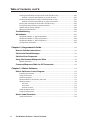
TPX 88 Matrix Switchers • Introduction
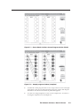
Extron twisted pair products’ attributes
Family
Transmitters
TP
Receivers
MTP
Transmitters
DA
Model
RGBHV
Component/
S-video Composite Audio
HDTV
TP T 15HD AV
Yes
Optional
Optional
1 Optional
1 Yes
Stereo
(2)
TP T 15HD A
Yes
Optional
Optional
Optional
Stereo
TP T 15HD 45/
TP T A 45
Yes
Optional
Optional
Optional
Stereo
TP T BNC
Yes
Optional
Optional
Optional
No
TP T BNC DA4
Yes
Optional
Optional
Optional
No
TP T 460/468
Yes
Optional
Optional
Optional
Stereo
TP T AV
No
No
No
Yes
Stereo
TP R BNC AV
Yes✡
Optional
Optional
1 Optional
1 Yes
Stereo
(2)
TP R BNC A
Yes✡
Optional
Optional
Optional
Stereo
✡
TP R 15HD A
Yes
Optional
Optional
Optional
Stereo
TP R AV
No
No
No
Yes
Stereo
MTP T 15HD A
Yes
Optional
Optional
Optional
Yes*
SW2/4/6 MTP T 15HD A
Yes
Optional
Optional
Optional
Yes*
MTP T 15HD RS
Yes
Optional
Optional
Optional
No
MTP T SV
No
No
Yes
No
No
MTP T SV A
No
No
Yes
No
Yes✝
MTP T SV A RCA
No
No
Yes
No
Yes✝
MTP T SV A AAP
No
No
Yes
No
Yes✝
MTP T SV A 45
No
No
Yes
No
Yes✝
MTP T CV
No
No
No
Yes
No
MTP T AV
No
No
No
Yes
Yes✝
MTP T AV RCA
No
No
No
Yes
Yes✝
MTP T AV AAP
No
No
No
Yes
Yes✝
MTP T AV 45
No
No
No
Yes
Yes✝
MTP DA4/8
✦
✦
✦
✦
✦
* MTP transmits or receives audio, but the TPX 88 and TPX 88 A cannot switch this TP device's audio.
✝ The TPX 88 and TPX 88 A switch the audio but cannot process it or output it locally.
✦ Video and audio capabilities are dependent on the MTP transmitter providing the input.
✡ The TPX 88 does not support the TP R receivers' automatic level and peaking feature or the input signal
detect feature (the receiver's power LED lights amber only). Support of the automatic level and peaking
and the signal detect features, requires the use of a TPX 88 A.
TPX 88 Matrix Switchers • Introduction
1-3
Introduction, cont’d
Extron twisted pair products’ attributes (continued)
Family
MTP
Receivers
Transmitter
VTT/
VTR
Receiver
*
✝
1-4
Model
RGBHV
Component/
S-video Composite Audio
HDTV
MTP R 15HD A
Yes
Optional
Optional
Optional
Yes*
MTP RL 15HD A
Yes
Optional
Optional
Optional
Yes*
MTP RL 15HD A SEQ
Yes
Optional
Optional
Optional
Yes*
MTP R 15HD RS
Yes
Optional
Optional
Optional
No
MTP RL 15HD RS
Yes
Optional
Optional
Optional
No
MTP RL 15HD RS SEQ
Yes
Optional
Optional
Optional
No
MTP R SV
No
No
Yes
No
No
MTP R SV A
No
No
Yes
No
Yes✝
MTP R SV A RCA
No
No
Yes
No
Yes✝
MTP R CV
No
No
No
Yes
No
MTP R AV
No
No
No
Yes
Yes✝
MTP R AV RCA
No
No
No
Yes
Yes✝
VTT001CM
Yes
No
No
No
No
VTT001 AAP
Yes
No
No
No
No
IN1404XT
Yes
No
No
No
No
VTR001CM
Yes
No
No
No
No
VTR001 AAP
Yes
No
No
No
No
MTP transmits or receives audio, but the TPX 88 and TPX 88 A cannot switch this TP device's audio.
The TPX 88 and TPX 88 A switch the audio but cannot process it or output it locally.
TPX 88 Matrix Switchers • Introduction
Transmission distances
The minimum reliable transmission distance between transmitters and receivers is
50 feet for most models. The maximum distance is determined by the output
frequency, resolution, and the transmitter/receiver family. The table below lists the
recommended maximum transmission distances for most transmitter/receiver
families using Extron Enhanced Skew-Free A/V UTP cable, terminated with CAT 5
rated connectors.
Refer to each product’s user manual to determine the ranges for that family of
products.
Recommended transmission ranges at 60 Hz
Video format
Composite video, S-video, and
component video and audio
640 x 480
800 x 600
1024 x 768
1280 x 1024
1600 x 1280
Maximum ranges
800" (245 m) – 1000" (300 m)
500" (150 m) – 1000" (300 m)
400" (120 m) – 800" (245 m)
300" (90 m) – 600" (185 m)
200" (60 m) – 450" (135 m)
150" (45 m) – 450" (135 m)
It is possible to exceed the recommended distances, however, image quality may
be reduced.
Extron recommends using the highest quality cable available and affordable,
with less than 8 nanoseconds/100 meters of skew (see Termination of TP
cable in chapter 2). We also recommend the use of pre-terminated and tested
cables. Cables terminated on site should be tested before use to ensure that
they comply with Category 5 specifications.
Extron Skew-Free A/V UTP cable is recommended for most applications.
CAT 5 cable can be satisfactorily used for some products (refer to each
product’s user manual). The system can be used with cable other than that
recommended, but video performance will be compromised and maximum
cable lengths and video resolutions must be decreased.
TPX 88 Matrix Switchers • Introduction
1-5
Introduction, cont’d
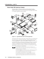
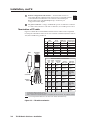
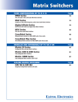
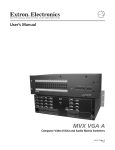
About Both TPX Switcher Models
The TPX switchers are single box solutions to simple twisted pair routing
applications (figure 1-1). Each input and output is individually isolated and
buffered, and any input(s) can be switched to any one or all outputs with virtually
no crosstalk or signal noise between channels.
Extron
VTT001
Video Camera
Twisted
Pair Transmitter
Extron
CPM101
CODEC
Extron
IN1404XT
VCR/DVD
ER
POW
er
smitt
Connector Plate
01CM
Pair
VTT0ted
Twis
Tran
O
T
INPU
Video Scaler
w/ UTP Output
VIDE
Speakers
ER
POW
Document Camera
w/ High Res Output
er
smitt
01CM
Pair
VTT0ted
Twis
Tran
O
T
INPU
VIDE
MAC
Extron
VTT001
Twisted
Pair Transmitter
Extron
TP T 15HD A
Laptop
Sound System
Twisted Pair
Transmitter
AUDIO
COMPU
ID PIN 4
ID PIN 11
TER
INPUT
Audio
0.3A
BUFFER
240V
ED
100-
LOCAL
H-SHIF
MONITO
T
R
TP
T 15H
D
1T23.
I.T.E
UT
Extron
VTR001
GND
TXTX +
RX RX +
OU
R
0Hz
50-6
S
TP
TE
MO
RE
8
L
422 0
RS-
Extron
TPX 88 A
R
1
232
7
RS-
L
8
R
6
7
L
6
R
5
5
UT
L
4 OU
S
ER
POW
TP
iver
01CM Rece
Pair
3
R
L
Twisted Pair
Matrix Switcher
R
4
DIO
AU UT
TP
OU
VTT0ed
Twist
8
2
7
6
Extron
VTR001
5
UT
S
INP
2
ER
POW
iver
01CM Rece
Pair
C SYNC
SOG
C VIDEO
N/C
VTT0ed
Twist
AUDIO
R
POWE
15V MAX
.34A
R
L
RGB
PUT
OUT
PC
AV
C SYNC
SOG
C VIDEO
N/C
AUDIO
R
POWE
15V MAX
.34A
R
L
RGB
AUDIO
PUT
OUT
COMPU
ID PIN 4
ID PIN 11
TER
BUFFER
ED
AV
H-SHIF
MONITO
T
INPU
T
INPU
Stereo
Audio
A
INPU
Twisted
Pair Receiver
Lobby
Twisted Pair
Receiver
T
T 15H
D
T
O
Stereo
Audio
LCD Projector #2
R
TP
VIDE
Extron
TP R 15HD A
Twisted Pair
Transmitter
LOCAL
Twisted
Pair Receiver
L
R
1
1
INPUT
INPU
1
L
R
L
4
Audio
T
O
VIDE
2
S
3
3
Extron
TP T 15HD A
System
Control
.
, CA
EIM
AH IN USA
AN DE
ED
LIST
MA
A
Extron
TP R 15HD A
Twisted Pair
Receiver
Presenters
Display
LCD Projector #1
Figure 1-1 — Typical TPX 88 A matrix switcher application
The TPX 88 switchers support I/O grouping, a feature that lets you virtually divide
the matrix into up to four smaller sub-switchers, making installation and control
easier. I/O grouping allows you to separate different signal types to avoid
connecting signal types from different, incompatible, transmitter/receiver families.
The TPX matrix switchers are housed in rack-mountable, 1U high, 17" wide metal
enclosures. The appropriate rack mounting kit is included with each switcher,
allowing you to mount the switcher in a standard 19" rack. Each model has an
internal 100 VAC to 240 VAC, 50/60 Hz, 25 watts, auto-switchable, power supply
that provides worldwide power compatibility.
Many twisted pair transmitters and receivers have the ability for one
component of the pair to provide power for the other (such as a TP R BNC A
providing the power for a TPT BNC).
The TPX 88 cannot power connected twisted pair transmitters and receivers.
The TPX 88 cannot switch the power that a twisted pair transmitter or
receiver supplies to a twisted pair receiver or transmitter.
In a twisted pair system that includes a TPX 88, both the twisted pair
transmitter and the twisted pair receiver must be powered locally. The
appropriate power supply is included with the transmitters and receivers.
1-6
TPX 88 Matrix Switchers • Introduction
The TPX switcher can be remotely controlled via its Remote (RS-232/RS-422) port.
The switchers are programmed with Extron’s Simple Instruction Set™ (SIS™), a set
of basic ASCII code commands that provide simple control through a third party
control system or PC without programming long, obscure strings of code.
The Remote port can be connected to a control system, a PC, or an Extron
MCP 1000 remote control panel and/or MKP 1000 remote keypad, MKP 2000
remote control panel, or MKP 3000 remote control panel.
About the TPX 88 A Switchers
Local audio outputs have volume and mute controls. The switcher’s local audio
outputs are on 5-pole, 3.5 mm captive screw connectors. These local outputs follow
the RJ-45 outputs. For example, if audio input 6 is tied to audio output 1, then the
TPX’s local audio output 1 is the input 6 audio. This is true regardless of whether
the audio follows the video or is broken away from the video in the routing of
signals between twisted pair transmitters and receivers.
The TP transmitters and receivers distribute audio in a proprietary digital
channel of the TP link.
The TPX 88 cannot switch this audio.
The TPX 88 A can switch this audio and extract it for the local connectors.
The audio distributed by certain VersaTools® MTP transmitter/receiver pairs is
incompatible with the audio extraction and processing capabilities of the
TPX 88 A.
The TPX 88 and the TPX 88 A cannot switch the audio that is distributed by
MTP RGB transmitters and receivers.
The TPX 88 can switch the audio that is distributed by MTP S-video and
composite video transmitters and receivers.
The TPX 88 A can switch the audio that is distributed by MTP S-video and
composite video transmitters and receivers but cannot extract it for the
local connectors.
On the TPX 88 A, the switching of the audio portion of the TP link can either be
linked with the video portion (audio follow) or independent of the video portion
(audio breakaway).
TPX 88 Matrix Switchers • Introduction
1-7
Introduction, cont’d
Features
Inputs — These switchers accept 8 sets of TP signals that are input from Extron
twisted pair transmitters on TP cable terminated with RJ-45 connectors. Each
transmitter creates the proprietary signal from its RGBHV, RGBS, RGsB,
RsGsBs, HDTV, component video, S-video, or composite video input. Most
transmitters also include either digital or differential analog audio on the
proprietary signal.
TP outputs — These switchers output 8 sets of TP signals for use by Extron twisted
pair receivers.
TPX 88 — The output proprietary signal includes the encoded video
(RGBHV, RGBS, RGsB, RsGsBs, HDTV, component video, S-video, or
composite video), but not the audio output by most TP transmitters.
However, if the input TP link originated from an MTP transmitter with audio,
the output proprietary signal also includes the audio portion of the link.
TPX 88 A — The output proprietary signal includes the encoded video
(RGBHV, RGBS, RGsB, RsGsBs, HDTV, component video, S-video, or
composite video) and audio.
Audio outputs (TPX 88 A only) — If the input TP link originated from a member of
the TP family of transmitters (see the table on page 1-3 and page 1-4), the
TPX 88 A outputs 8 stereo audio outputs, balanced or unbalanced, on 3.5 mm,
5-pole captive screw terminals.
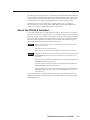
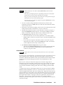
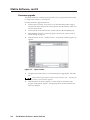
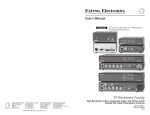
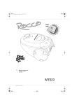
Audio gain and attenuation (TPX 88 A only) — Users can set the input level of
audio gain or attenuation (-18 dB to +24 dB) for the signal that is output
locally. Gain and attenuation can be set via the RS-232/RS-422 link or from
the front panel. Individual input audio levels can be adjusted so there are no
noticeable volume differences between sources (figure 1-2).
dBu
dBv
+10
+7
+4
+1
-2
-5
-8
-12
+8
+5
+2
-1
-3
-7
-10
-14
AUDIO
COMPUTER
ID PIN 4
ID PIN 11
INPUT
Consumer VCR
TP T 15HD A
PC
H-SHIFT
BUFFERED
dBu
+10
+7
+4
+1
-2
-5
-8
-12
LOCAL MONITOR
TP T 15HD A
Audio
Inputs
Low Audio
Output Level
I
N
P
U
T
I/O
AUTO SWICH EXECUTIVE
ACUTIVE
MODE
O
U
T
P
U
T
1
1
VIDEO
AUDIO
2
2
1
3
3
2
4
4
3
5
5
4
6
6
5
7
7
6
8
8
I/O
I
N
P
U
T
7
O
U
T
P
U
T
8
10
VIEW 11
12
AUDIO
VIDEO / AUDIO SWITCHER
AUDIO
VOLUME
MUTE ALL
CONF/SAVE
ENTER
-dB
ESC
+dB
dBu
dBv
+10
+7
+4
+1
-2
-5
-8
-12
+8
+5
+2
-1
-3
-7
-10
-14
AUDIO
COMPUTER
INPUT
ID PIN 11
BUFFERED
PC
H-SHIFT
LOCAL MONITOR
TP T 15HD A
Audio System
TP T 15HD A
No noticeable volume
differences between sources
Audio
Inputs
High Audio
Output Level
Pro CD Player
Figure 1-2 — Audio gain and attenuation
1-8
TPX 88 A
TWISTED PAIR SWITCHER
TPX88 A Twisted Pair Metrix Switcher
ID PIN 4
Output
Level
AUDIO
SW SERIES
VIDEO
PRESET
9
dBv
+8
+5
+2
-1
-4
-7
-10
-14
TPX 88 Matrix Switchers • Introduction
Audio output volume (TPX 88 A only) — The audio level of each local output can
be adjusted through a range of 100% (no attenuation) to 0% (full attenuation).
The audio level can be adjusted under front panel or RS-232/RS-422 control.
Switching flexibility — Provides individually buffered, independent matrix
switched outputs with audio follow and audio breakaway for the TPX 88 A.
•
Any input to any or all outputs
•
Quick multiple tie — Multiple inputs can be switched to multiple outputs
simultaneously. This allows all displays (outputs) to change from source to
source at the same time.
•
Audio follow (TPX 88 A) — The audio portion of the TP link input can be
switched with the corresponding video portion of the input TP link. This
feature allows any audio signal to be selected with any video signal
simultaneously to one or all outputs in any combination. Audio follow
switching can be done via front panel control or under RS-232/RS-422 remote
control.
•
Audio breakaway (TPX 88 A) — The audio portion of the TP link input can
be broken away from its corresponding video portion of the input TP link.
Audio breakaway switching can be done via front panel control or under
RS-232/RS-422 remote control.
Audio from a transmitter in the MTP family cannot be broken away.
Operational flexibility — Operations such as input/output selection, setting of
presets, and adjustment of audio output levels (TPX 88 A only) can be
performed on the front panel or over the RS-232/RS-422 link. The
RS-232/RS-422 link allows remote control via a PC or control system.
•
Front Panel Controller — The TPX front panel controller feature supports
touch-of-a-button input and output selection, preset creation and selection,
and (TPX 88 A only) audio output volume control. The front panel features
large, positive touch, illuminated input and output pushbuttons that can be
labeled with text or graphics.
•
Windows-based control program — For RS-232/RS-422 remote control from
a PC, Extron includes its Windows-based control software with every matrix
switcher. The control program provides a versatile range of operational
options with its graphical interface and drag-and-drop/point-and-click
operation. The Windows-based control program also has an emulation mode
that lets you create a switcher configuration file at the home office and then
download it for use by the switcher on site.
•
Simple Instruction Set (SIS™) — The remote control protocol uses Extron’s
SIS for easy programming and operation.
•
Remote control — The matrix switchers are remote controllable, using the
MCP 1000 master control panel and any combination of MCP 1000 slave
control panels and/or MKP 1000 slave control keypads. The remote control
devices are easy to use and provide tactile buttons for quick selection. Each
MCP 1000 can be used for one-touch switching for a particular output and
selecting global presets. Each MKP 1000 dedicated to an output can be used
to select a different input for that output or to select a preset.
Labeling — Extron’s label software ships with every Extron matrix switcher. You
can create labels to place in the front panel I/O buttons, with names,
alphanumeric characters, or color bitmaps for easy and intuitive input and
output selection. Alternatively, labels can be made with any Brother P-Touch
or comparable labeler.
TPX 88 Matrix Switchers • Introduction
1-9
Introduction, cont’d
Global memory presets — 16 global memory presets are a time-saving feature that
lets you set up and store input/output configurations in advance and then
recall those configurations when needed with a few simple steps.
I/O grouping — Allows the matrix to be virtually divided into up to four smaller
sub-switchers, making installation and control easier. I/O grouping allows
specific outputs, such as those for a specific family of twisted pair receivers,
with a specific signal format, to be grouped together. Switching between I/O
groups is not possible from the front panel.
Rack mount — Rack mountable in any conventional 19" wide rack.
Front panel security lockout (executive mode) — If a TPX switcher is installed in
an open area, where operation by unauthorized personnel may be a problem,
a security lock-out feature can be implemented. When the front panel is
locked, a special button combination is required to unlock the front panel
controller before it can be operated.
Power supply — Includes an internal 100 VAC to 240 VAC, 50/60 Hz, 25 watts
auto-switchable power supply, which provides worldwide power
compatibility.
1-10
TPX 88 Matrix Switchers • Introduction
TPX 88 Twisted Pair Matrix Switchers
2
Chapter Two
Installation
Mounting the Switcher
Cabling and Rear Panel Views
Installation, cont’d
Installation
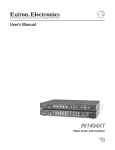
Mounting the Switcher
The TPX switchers are housed in rack-mountable, 1U high, 17" wide metal
enclosures. The appropriate rack mount kit is included with the switchers,
allowing you to mount the switcher in a standard 19" rack. Rack mount the
switcher as follows:
1.
If rubber feet were installed on the bottom of the switcher, remove them.
2.
Attach the rack mount brackets to the switcher with eight #8 machine screws,
provided (figure 2-1).
O
DI
AU
8A
X 8 ER
TPSWITCH
ME
LU
VO
I/O
O
VIDE
O
DI
AU
L
E AL
MUT
D
ISTE
TW
IR
PA
VIEW
8
7
6
5
4
3
2
I
N
P
U
T
1
O
U
T
P
U
T
1
8
I
N
P
U
T
O
U
T
P
U
T
ET
ES
PR
C
ES
R
TE
EN
7
6
5
4
3
2
Figure 2-1 — Rack mounting a TPX switcher
2-2
3.
Insert the switcher into the rack, align the holes in the mounting bracket with
those of the rack.
4.
Secure the switcher to the rack using the supplied machine screws.
TPX 88 Matrix Switchers • Installation
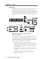
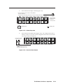
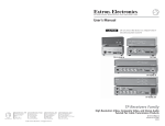
Cabling and Rear Panel Views
All connectors are on the rear panel. The switcher can connect to as many as eight
compatible twisted pair transmitters for input and twisted pair receivers for output.
The TPX 88 A has output connections for eight local audio outputs. See the tables
on page 1-3 and page 1-4 for audio compatibility. Figure 2-2 shows the rear panel
of a TPX 88 A twisted pair matrix switcher.
The rear panel of the TPX 88 has most of the same features as the TPX 88 A,
but without the local audio connectors.
3
R
L
R
1
L
R
2
L
3
R
L
R
L
4
R
5
L
R
6
L
100-240V
R
7
0.3A
8
REMOTE
AUDIO
OUTPUTS
RS-232
ANAHEIM, CA.
MADE IN USA
6
GND
TXTX +
RX RX +
L
RS-422
1
2
3
4
INPUTS
1
5
6
7
8
1
2
3
4
OUTPUTS
2
5
6
7
8
50-60Hz
5
4
Figure 2-2 — TPX 88 A twisted pair matrix switcher with audio
CAUTION
Do not connect this device to a computer data or telecommunications
network
RJ-45 termination must comply with the TIA/EIA T 568A or TIA/EIA T 568B
wiring standards for all connections.
1
Inputs connectors — Connect one end of a TP cable to each of these RJ-45
female connectors. Connect the other end of each cable to a compatible
twisted pair transmitter. See Termination of TP cable in this chapter.
2
Outputs connectors — Connect one end of a TP cable to each of these RJ-45
female connectors. Connect the other end of each cable to a compatible
twisted pair receiver. See Termination of TP cable in this chapter.
Extron skew-free A/V cable is recommended for all applications.
CAT 5 and CAT 6 cable can be used for TP and VTT transmitters and
receivers.
CAT 6 cable is not recommended for MTP transmitters and receivers.
The TP R receivers’ automatic level and peaking and signal detect features
require the use of a TPX 88 A.
To support TP R receivers’ level and peaking features, either the automatic or
manual adjustment, use TP cables of approximately the same length on all TP
inputs ( 1 ) and on all TP outputs ( 2 ).
3
Audio Outputs connectors (TPX 88 A only) — These 3.5 mm, 5-pole captive
screw connectors output unamplified, unbalanced or balanced line level
audio. The local audio outputs follow the RJ-45 outputs; that is, if input 6 is
tied to output 1, then audio output 1 is the input 6 audio. See Audio outputs
connectors (TPX 88 A only) in this chapter.
These audio outputs are not available if the TP input is from an MTP family
transmitter.
4
Remote connector — Connect a host device to the TPX 88 via this 3.5 mm,
5-pole captive screw connector for serial RS-232/RS-422 control. See Remote
port configuration in this chapter.
TPX 88 Matrix Switchers • Installation
2-3
Installation, cont’d
5
6
Remote configuration DIP switches — Set these DIP switches to
select either RS-232 or RS-422 serial control protocol. Set DIP switches
1 and 2 both down for RS-422 or set switches 1 and 2 both up for
RS-232. DIP switch 3 should always be up. See Remote port
configuration in this chapter.
RS-232
RS-422
AC power connector — Plug a standard IEC power cord into this connector
to connect the switcher to a 100 VAC to 240 VAC, 50 or 60 Hz power source.
Termination of TP cable
Figure 2-3 details the recommended termination of TP cables for the compatible
twisted pair transmitters and receivers in accordance with the TIA/EIA T 568A or
TIA/EIA T 568B wiring standards.
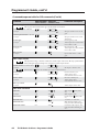
TP and VTT transmitters and receivers
Side
Clip Down
12345678
Composite video
and audio signal
568 B
wire color
RGBHV and
audio signal
1 White-green
White-orange
Red/V. sync +
Video +
2 Green
Orange
Red/V. sync –
Video –
Pin
568 A
wire color
3* White-orange White-green
Audio +
Audio+
4 Blue
Blue
Green +
Reserved
5 White-blue
White-blue
Green –
Reserved
6* Orange
Green
Audio –
Audio –
7 White-brown
White-brown
Blue/H. sync + No signal
8 Brown
Brown
Blue/H. sync – No signal
MTP transmitters and receivers
568 A
Wire
Pin color
12345678
568 B
Wire
color
Composite
video MTP
signal
1 Whitegreen
Whiteorange
Video +
Luma (Y) +
Red/
V. Sync +
2 Green
Orange Video –
Luma (Y) –
Red/
V. Sync –
NONE
NONE
Mono audio +
or RS-232 +
(MTP 15HD
only)
Blue
Audio
left +
Chroma (C) &
audio left +
Green +
Whiteblue
Audio
left –
Chroma (C) &
audio left –
Green –
NONE
NONE
Mono audio –
or RS-232 –
(MTP 15HD
only)
3*
RJ-45
connector
White- Whiteorange green
4 Blue
Twisted
Pairs
5
Whiteblue
S-video
MTP signal
1&2
3&6 4&5 7&8
6* Orange Green
RGB video
MTP signal
Whitebrown
Whitebrown
Audio
right +
Audio right+
Blue/
H. Sync +
8 Brown
Brown
Audio
right –
Audio right –
Blue
H. Sync –
7
* The TPX 88 A switches wire pair 3 and 6.
The TPX 88 does not switch wire pair 3 and 6.
Audio or serial data from an RGB video MTP is incompatible with both TPX models. They cannot be switched.
NOTE If you are using Enhanced Skew-Free™ A/V cable, use the TIA/EIA T 568A standard only.
Figure 2-3 — TP cable termination
2-4
TPX 88 Matrix Switchers • Installation
Enhanced Skew-free A/V cable is not recommended for Ethernet/LAN
applications.
This cable is specially designed for compatibility with Extron’s Twisted Pair
products that are wired using the TIA/EIA 568 A standard.
The green, brown, and blue pairs of this cable have virtually identical lengths
and should be used to transmit the RGB signals.
The orange pair of this cable has a different length and should not be used to
transmit the RGB signals.
•
You can use either wiring standard, but ensure that you use the same
standard on both ends of both cables; the cable from the transmitter and the
cable from the receiver.
•
Ensure that you terminate the RJ-45 connectors for each cable properly for the
family (TP, VTT, MTP) of transmitter or receiver connected.
•
On RGB video MTPs, the audio or serial data that is carried on wire pairs 3
and 6 is incompatible with the TPX 88 A. The TPX 88 A cannot switch the
audio or serial data, output the audio locally, or break the audio away.
•
The TPX 88 does not switch or process wire pair 3 and 6.
•
°
Most TP transmitter/receiver audio (audio that is associated with the
RGBHV link) is carried on wire pair 3 and 6, so the TPX 88 cannot switch
this audio.
°
On S-video and composite video MTPs, audio is carried on wire pairs
other than pair 3 and 6, so the TPX 88 switches this audio. The TPX 88
cannot output the audio locally or break it away.
The TPX 88 A switches and processes wire pair 3 and 6.
°
The TPX 88 A switches and processes the proprietary digital audio link
that is associated with the TP transmitter/receiver family, which is
carried on wire pair 3 and 6.
Cable testing
Systems that use Extron’s skew-free UTP cable do not need to be tested for
skew.
To ensure proper cable termination, each transmission cable system that uses CAT 5
cable should be tested. Testing the cable between the RJ-45 connections at the
transmitter and TPX 88 (transmitter cable system) and between the TPX 88 and the
receiver (receiver cable system) gives the most accurate indications of cable
problems.
There are two varieties of cable runs: simple runs, in which a single cable is
terminated only at the transmitter, TPX 88, and receiver, and complex runs, which
can include patch bays and multiple terminations and lengths of cable. In either
case, the entire transmitter cabling system and receiver cabling system should be
tested.
A complete test measures cable length and tests the wire map, attenuation, NEXT,
PSNEXT, ELFEXT, PSELFEXT, return loss, ACR and PSACR. All of these tests are
critical for digital data transfer, but not for analog video. While all of these tests are
important indicators of the quality of the cable termination, the most critical testing
parameters for video transfer are wire map (T-568-A or T-568-B termination) and
pair length measurements. The largest concern is equalization of skew between
cable pairs. Cable systems of 300 feet (91 meters) or less should exhibit no
transmission problems if they pass at least CAT 5e or preferably CAT 6-D5 channel
certification testing.
TPX 88 Matrix Switchers • Installation
2-5
Installation, cont’d
The Microtest OMNI SCANNER 2 performs comprehensive certification testing to
the proposed CAT 6 standards. Other manufacturers also make testing equipment.
The tests include advanced diagnostics for troubleshooting the cause and location
of many cable and termination problems. For simple installation testing, the
Microtest MICRO SCANNER PRO tests wire map and cable length, including
individual cable pair length.
The manufacturing process for network (CAT 5) UTP cable leads to a condition
called pair skew. Skew exists between pairs when the physical length of one wire
pair is different from another. As the transmission cable length increases, the
amount of skew increases. Skew affects the displayed image when the differential
length between wire pairs exceeds 2 feet, causing the timing of the red, green, and
blue video signals to appear out of alignment (horizontal registration errors). A
white vertical line on a black field can appear as individual red, green, and blue
lines that are close together; the signal transmitted on the shortest wire pair leads
the other colors and appears to the left on the display.
Pair skew can be measured with test equipment. UTP cable test equipment
measures and reports wire pair length. In certain circumstances, the report on the
various pair lengths can be used in equalizing pair skew.
If test equipment is not available, skew can be identified by viewing a crosshatch
test pattern with a critical eye to determine if either the red, green, or blue video
image leads (appears to the left of) the other two video images.
For best results when using CAT 5 cable in A/V applications, pair skew needs to be
equalized. Extron suggests several ways to equalized the pair skew as follows.
The design of Extron’s Skew-Free A/V UTP cable minimizes pair skew to the
point that equalization is not required.
If there are different cable types and/or big differences in input cable length,
skew compensation will not work.
Equalizing pair skew with Skew Equalizers
Try using the following methods to minimize or eliminate pair skew:
•
If using MTP 15HD (RGB video) receivers, switch to SEQ versions of the
receivers.
•
Install separate SEQ 100 15HD or SEQ 100 BNC Skew Equalizers on the
receivers’ video outputs and adjust the skew for the leading video image.
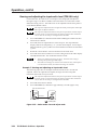
Equalizing pair skew with skew compensation cables
The nominal velocity of propagation (NVP — the speed at which the signal travels
on the transmission line, measured as a percentage of the speed of light) of TP cable
is very close to that of conventional coaxial cable. The similarity in NVP means
that, when all transmitter cables systems use the same cable type and are
approximately equal in length, by adding an additional length of coax, equal to the
length of pair skew, placed on the receiver’s output, you can equalize the effects of
pair skew (figure 2-4).
If UTP cable test measurement cannot be done, pair skew can still be equalized,
assuming that all of the transmitter cable systems are equal, by viewing a
crosshatch test pattern with a critical eye. Examine the test pattern for loss of
horizontal registration and, through a process of trial and error, equalize any pair
skew with coax extensions on the red, green, and/or blue outputs.
Extron skew compensation coax cables are available in lengths of 2 through 20 feet,
see Appendix A for part numbers.
2-6
TPX 88 Matrix Switchers • Installation
IF cable measurement
of all cables indicates
that the pair with wires
1 and 2 is three feet shorter
than the other signals
(total for all cables)...
AU
DIO
CO
MP
UT
ER
INP
UT
ID PIN 4
ID PIN 11
TP T 15HD A
BU
FFE
RE
D
LO
CA
L MO
NIT
OR
H-S
HIF
T
CAT
5T
15
HD
A
0.3A
240V
100-
CA.
M,
HEI USA
IN
ANADE
MA
GND
TXTX +
RX RX +
0Hz
50-6
TE
MO
RE
R
L
422
RS-
R
232
RS-
7
L
8
R
6
7
L
6
5
R
5
S
UT
TP
L
4 OU
3
R
L
R
4
DIO
AU TS
TPU
OU
2
1
3
TP R BNC A
L
R
8
2
L
7
6
R
1
5
L
S
UT
4
INP
3
2
1
ER
DC
POW
.5A
15V
TPX88 A
R
AU
DIO
L
B
A
SOG
C SYNC
PC Computer
L
R
V
B
RG
B
V
H/HTPUT
OU
G
R
RG
Pair RGB video
1, 2 Red
4, 5 Green
7, 8 Blue
B
INP
UT
CAT 6 TP Cable
... THEN insert a three foot
extension cable to equalize
UTP skew for red video.
LCD Projector
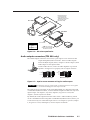
Figure 2-4 — Pair skew equalization
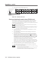
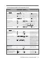
Audio outputs connectors (TPX 88 A only)
The Audio Outputs connectors are 3.5 mm, 5-pole captive screw connectors that
output unamplified, line level audio. The local audio outputs
follow the RJ-45 outputs; that is, if input 6 is tied to output 1, then
audio output 1 is the input 6 audio.
Connect audio devices, such as an audio amplifier or powered
speakers. See figure 2-5 to properly wire an output connector.
Tip
Ring
Sleeve (s)
Tip
Ring
Tip
See caution
Sleeve
Tip
See caution
Unbalanced Output
Balanced Output
Figure 2-5 — Captive screw connector wiring for audio output
CAUTION
Connect the sleeve to ground (Gnd). Connecting the sleeve to a negative
(-) terminal will damage the audio output circuits.
The audio level for each input can be can be individually set, using the front panel
or under RS-232/RS-422 control, to ensure that the output level does not vary from
input to input. See chapter 3, Operation, chapter 4, Programmer’s Guide, and
chapter 5, Switcher Software for details.
By default, the audio output follows the video switch. Audio breakaway, which
can be commanded via the front panel or under RS-232/RS-422 control, allows you
to select from any one of the audio input sources. See chapter 3, Operation, chapter
4, Programmer’s Guide, and chapter 5, Switcher Software for details.
TPX 88 Matrix Switchers • Installation
2-7
Installation, cont’d
When making connections for the TPX 88 A from existing audio cables, see
figure 2-6. A mono audio connector consists of the tip and sleeve. A stereo
audio connector consists of the tip, ring and sleeve. The ring, tip, and sleeve
wires are also shown on the captive screw audio output connector diagram,
figure 2-5.
Tip (+)
Ring (-)
Tip (+)
Sleeve ( )
Sleeve ( )
3.5 mm Stereo Plug Connector
(balanced)
RCA Connector
Figure 2-6 — Typical audio connectors
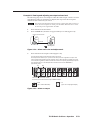
Remote port configuration
GND
TXTX +
RX RX +
The Remote port is a 3.5 mm, 5-pole captive screw connector for serial
RS-232/RS-422 control of the TPX 88. Wire the connector as shown in figure 2-7
and connect a host device, such as a computer, touch panel control, or RS-232
capable PDA.
Pin RS-232 Function
RS-422 Function
Gnd Gnd Signal ground Gnd Signal ground
TX- Transmit data (-)
TX— Not used
TX+ TX+ Transmit data TX+ Transmit data (+)
RX- Receive data (-)
RX— Not used
RX+ Receive data (+)
RX+ RX+ Receive data
RS-232
RS-232
RS-422
Settings
RS-422
RS-232
Settings
RS-422
Figure 2-7 — Remote connector
RS-422 implementation may vary between computers or controls systems.
Connect the control cable as shown in figure 2-7. If the serial communications
link with the TPX switcher does not work, try reversing the polarity of the TX
and RX signal lines.
Set Remote Configuration DIP switches 1 and 2 either both down to select RS-422
serial control protocol or both up to select RS-232. DIP switch 3 should always be
up.
If desired, connect an MCP 1000 remote control panel master unit or MKP 2000 or
MKP 3000 remote control panel to the switcher’s Remote connector. You can also
connect an MKP 1000 remote keypad or MCP 1000 slave unit to the MCP 1000
master unit. Refer to the connected device’s manual for details.
See chapter 4, Programmer’s Guide, for definitions of the SIS commands and
chapter 5, Matrix Software for details on how to install and use the control software.
2-8
TPX 88 Matrix Switchers • Installation
TPX 88 Twisted Pair Matrix Switchers
3
Chapter Three
Operation
Front Panel Controls and Indicators
Operations
Troubleshooting
Worksheets
Operation, cont’d
Operation
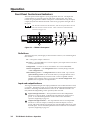
Front Panel Controls and Indicators
The front panel controls (figure 3-1) are grouped into four sets. The input and
output buttons are grouped on the left side of the control panel. The control
buttons are grouped in the middle of the panel. On the TPX 88 A only, the input/
output (I/O) selection button and audio controls are grouped on the right side of
the panel.
The TPX 88 is identical to the TPX 88 A, with the exception that it does not
have I/O selection or audio controls. These controls are marked with an
asterisk (*) in figure 3-1.
1
I
N
P
U
T
1
1
O
U
T
P
U
T
2
2
3
3
4
4
5
5
6
6
7
7
8
8
2
3
5
PRESET
VIEW
ENTER
ESC
4
6
9*
I/O
I
N
P
U
T
O
U
T
P
U
T
8*
10*
AUDIO
VIDEO
AUDIO
VOLUME
MUTE ALL
TPX 88 A
TWISTED PAIR SWITCHER
7*
Figure 3-1 — TPX 88 A front panel
Definitions
The following terms, which apply to Extron matrix switchers, are used throughout
this manual:
Tie — An input-to-output connection.
Set of ties — An input tied to two or more outputs. (An output can never be tied
to more than one input.)
Configuration — Consists of one or more ties or one or more sets of ties.
Current configuration — The configuration that is currently being used (also
called configuration 0).
Global memory preset — A configuration that has been stored. Up to sixteen
global memory presets can be stored in memory. The input buttons select
the desired preset memory location to load or retrieve a preset. When a
preset is retrieved from memory, it becomes the current configuration. One
preset can be assigned to each input button.
Input and output buttons
The large, illuminated input and output pushbuttons can be labeled with text and/
or graphics. The buttons can be set to provide amber background illumination all
the time or the background illumination can be set off. The buttons blink or are
fully illuminated (depending on the operation) when selected.
3-2
1
Input 1 through 8 buttons — The input buttons have three independent
functions: to select an input, to identify the selected inputs, and to select a
preset. A more detailed explanation of these functions is included in
Operations, beginning on page 3-5.
2
Output 1 through 8 buttons — The output buttons have four independent
functions: to select an output, to identify the selected outputs, to select a
preset, and (on the TPX 88 A) to display the user-adjustable audio level of the
selected input. A more detailed explanation of these functions is included in
Operations, beginning on page 3-5.
TPX 88 Matrix Switchers • Operation
Control buttons
3
Preset button and LED — The Preset button saves a configuration as a preset,
or recalls and makes active a previously-defined preset. The Preset LED
indicates save mode when it is blinking and recall mode when it lights
steadily.
4
Enter button — The Enter button saves changes when you set up a new
configuration. To create a simple configuration:
5
•
(TPX 88 A only) specify video, audio, or both [see the I/O button ( 7* )
and the Video and Audio LEDs ( 8* )]
•
Press the desired input button (
•
Press the desired output buttons (
•
Press the Enter button.
1
)
2
)
View button and LED — The View button selects a view-only mode that
allows the display of the current configurations. The view-only mode helps
prevent changing configurations by accident. When lit, the View LED
indicates that the switcher is in view-only mode.
In view-only mode, pressing any input button ( 1 ) or output ( 2 ) button
lights the buttons for the input and all outputs that are a part of that set of
ties. Pressing the button for any unassigned output lights only the buttons for
all of the unassigned outputs. No input button is lit.
6
Esc button — The Esc button cancels operations or selections in progress and
resets the front panel button indicators. The Esc button does not reset the
current configuration or any presets. On the TPX 88 A, the Esc button does
not reset the video and/or audio selection or any audio gain or attenuation
settings.
TPX 88 Matrix Switchers • Operation
3-3
Operation, cont’d
I/O controls (TPX 88 A only)
When creating or viewing a configuration, you must specify whether the
configuration applies to video, audio, or both. This is done with the I/O selection
button ( 7* ) and indicated by the Video and Audio ( 8* ) LEDs.
7*
I/O button — The I/O button selects video, audio, or video and audio for
input selection.
8*
Video and Audio LEDs — The Video and Audio LEDs indicate whether
video, audio, or video and audio will be selected using the Input and output
buttons ( 1 and 2 ).
Pressing the I/O button advances through a cycle of video and/or audio
selection as follows: {default} video and audio, {press} video only, {press}
audio only, {press} video and audio, and so on (figure 3-2).
I/O
I/O
I/O
I/O
VIDEO
VIDEO
VIDEO
VIDEO
AUDIO
AUDIO
AUDIO
AUDIO
Default
(Video &
audio)
= Lit LED,
Press
Video
only
Press
Audio
only
Press
Video &
audio
= unlit LED
Figure 3-2 — Video and/or audio selection cycle
Audio controls (TPX 88 A only)
9*
Mute All button and LED — The Mute All button toggles the mute function
on and off for all of the local audio outputs (those on the rear panel 3.5 mm
captive screw connectors).
10*
Volume knob — The volume knob sets the audio gain or attenuation level for
the selected input and the volume level for the selected output. The level and
volume adjustments affect only the local audio outputs (those on the rear
panel 3.5 mm captive screw connectors).
The current input audio level setting for the selected input is displayed by the
output buttons. A more detailed explanation of audio gain adjustment is
included in Viewing and adjusting the input audio level (TPX 88 A only)
beginning on page 3-20.
The current output volume level setting for the selected output is displayed
by the input buttons. A more detailed explanation of audio volume
adjustment is included in Viewing and adjusting the output volume (TPX 88 A
only) beginning on page 3-22.
3-4
TPX 88 Matrix Switchers • Operation
Button icons
The numbered translucent covers on the pushbuttons can be removed and replaced
to insert labels behind the covers.
Input and output inserts can be created easily with Extron’s Button Label Generator
software, which ships with every Extron matrix switcher. Each input and output
can be labeled with names, alphanumeric characters, or even color bitmaps for easy
and intuitive input and output selection.
Figure 3-3 shows a sample set of button inserts in a typical configuration. The icons
in the input buttons show the video sources that drive the TP transmitters that are
connected to the inputs. The TP receivers that are connected to the outputs drive
the video displays that are shown by the icons in the output buttons.
I
N
P
U
T
O
U
T
P
U
T
DVD
VCR
Projector Picture
Plasma Picture
Document
Camera
3
4
4
Computer
5
VTG 200
6
Figure 3-3 — Sample button icons
See chapter 5, Matrix Software, for details on using the labeling software. See
Appendix A, Reference Information, for blank labels and procedures for removing
and replacing the translucent covers.
Operations
The following paragraphs detail the power up process and provide sample
procedures for creating ties, sets of ties, and configurations; changing a
configuration; viewing ties, sets of ties, and configurations; saving a preset;
recalling a preset; and viewing and adjusting the audio level.
Power
Power is automatically applied when the power cord is connected to an AC source.
When AC power is applied, the switcher performs a self-test that cycles the front
panel I/O button indicators on and off from left to right lit green, right to left lit
red, and left to right lit amber. An error-free power up self-test sequence leaves the
Video and/or the Audio LEDs on (TPX 88 A only), all other LEDs unlit, and all I/O
buttons either unlit or showing background illumination.
The current configuration and all presets are saved in non-volatile memory. When
power is applied, the last current configuration is retrieved. The previous presets
remain intact.
If an error occurs during the self-test, the switcher locks up and will not operate. If
your switcher locks up on power-up, call the Extron S3 Sales & Technical Support
Hotline.
TPX 88 Matrix Switchers • Operation
3-5
Operation, cont’d
I/O grouping
I/O grouping is an RS-232/RS-422 controlled feature that allows you to subdivide
the front panel control of the matrix into up to four smaller functional subswitchers. Inputs and outputs can be assigned to one of four groups (figure 3-4) or
not assigned to any group. Once assigned to a group, inputs and outputs can only
be tied within that group from the front panel. For example, a front panel operator
cannot tie an input that is assigned to group 1 to an output that is assigned to group
2. Ungrouped inputs and outputs can be switched to outputs and inputs in any
group.
INPUTS
FREEZE
RGB
FREEZE
1
UNIVERSAL COMPOSITE
2
PICTURE ADJUSTMENTS
S-VIDEO
SDI
4
5
3
CENTER
SIZE
BRT/CONT
COL/TNT
ADJUST
ZOOM
DETAIL
MENU
NEXT
USP 405
UNIVERSAL SIGNAL PROCESSOR
I
N
P
U
T
O
U
T
P
U
T
1
1
2
2
Group 1
3
3
4
4
Group 2
5
5
6
6
7
7
8
8
I
N
P
U
T
Computer #1
O
U
T
P
U
T
USP 405
2 input, 3 output
RGBHV matrix
Input
7 8
Group 3
Computer #2
Projector
6 Output
7
8
Group 3
Monitor
3 input, 3 output
MTP S-video matrix
3 input, 2 output
MTP composite matrix
Camera #1
Document Camera
Input
1 2 3
1
2 Output
Monitor
VCR
Group 1
Input
4 5 6
INPUTS
FREEZE
RGB
FREEZE
1
PICTURE ADJUSTMENTS
UNIVERSAL COMPOSITE
2
S-VIDEO
SDI
4
5
3
CENTER
SIZE
BRT/CONT
COL/TNT
ADJUST
ZOOM
DETAIL
MENU
NEXT
USP 405
UNIVERSAL SIGNAL PROCESSOR
USP 405
1
RGB
2
3
RGB/YUV VIDEO/
S-VIDEO
4
5
6
VIDEO/
S-VIDEO
VIDEO/
S-VIDEO
SDI
MENU
PICTURE ADJUSTMENTS
TAKE
COL/TNT BRT/CONT
DETAIL
SIZE
ADJUST
CENTER
DVS 406
NEXT
DIGITAL VIDEO SCALER
DVS 406
3
Output
4
5
Group 2
Camera #3
Monitor
DVD
Monitor
Figure 3-4 — I/O grouping of compatible twisted pair
transmitter/receiver pairs
The I/O groups can be set up only by using the RS-232/RS-422 port and either the
SIS or the Windows control program (see chapter 4, Programmer’s Guide, and
chapter 5, Matrix Software. Ties between groups (an input in group 1 tied to an
output in group 2) can be created under RS-232/RS-422 control. Presets can also be
created under RS-232/RS-422 control that tie inputs and outputs across group
boundaries. These presets are selectable from the front panel.
Suggested applications for the I/O grouping feature include:
3-6
•
Segregating specific twisted pair transmitter and receiver formats to prevent
a transmission from one family of twisted pair transmitters from being
inadvertently applied to a twisted pair receiver from an incompatible family.
See the table on page 1-3 and page 1-4 for twisted pair transmitter and
receiver compatibility.
•
Segregating specific video formats to prevent an input in one video format
from being inadvertently applied to an output device that supports another
video format.
•
Segregating input and output devices that are in separate rooms.
•
Isolating video from being displayed on specific output devices for
operational security reasons.
TPX 88 Matrix Switchers • Operation
The I/O groups created under RS-232/RS-422 control can result in front panel
indications that are different from indications when grouping is not used. In the
following paragraphs, the effects of I/O grouping on the front panel indications are
included where applicable.
Creating a configuration
The current configuration can be changed using the front panel buttons. To change
the current configuration, do the following:
1.
Press the Esc button to clear any input buttons, output buttons, or control
buttons that may be lit.
2.
(TPX 88 A only) Select to configure video, audio, or both by pressing the I/O
button. The Video and/or Audio LEDs light to indicate that video and/or
audio are selected.
3.
Select the desired input and output(s) by pressing the input and output
buttons.
Input and output buttons light amber to indicated video and audio ties. The
buttons light green to indicated video only ties. The buttons light red to
indicate audio only ties.
To indicate current ties, the buttons for tied outputs light the appropriate color
(amber, green, or red) when an input is selected. To clear unwanted outputs
press and release the associated lit output buttons.
4.
Press and release the Enter button.
5.
Repeat steps 1 through 4 to create additional ties until the desired
configuration is complete.
•
Only one video input and one audio input can be tied to an output but
multiple outputs can be tied to a single input.
•
If a tie is made between an input and an output, and the selected output
was previously tied to another input, the older tie is broken in favor of the
newer tie.
•
If an input with no tie is selected, only that input’s button lights. The
button lights the appropriate color for the video and/or audio selection.
•
When the Video and Audio LEDs are lit, if an input with an audio tie but
no video tie is selected, the input’s button lights amber and the output
button lights red.
•
If the input button for a grouped input is pressed, and then the output
button for an output in a different group is pressed, the associated output
button does not light. That output cannot be tied to an input from a
different group using the front panel. The associated input button
remains lit.
TPX 88 Matrix Switchers • Operation
3-7
Operation, cont’d
Example 1: Creating a set of video and audio ties
The following steps show an example in which input 5 is tied to outputs 3, 4, and 8.
Where an explanation is helpful, the steps show the front panel indications that
result from your action.
This example assumes that there are no ties in the current configuration.
1.
Press and release the Esc button.
2.
TPX 88 A only — To select video and audio for the tie, if necessary, press and
release the I/O button until the LEDs light (figure 3-5).
I/O
The video LED lights green when video is selected.
The audio LED lights red when audio is selected.
VIDEO
AUDIO
Press the button to cycle
through the selections.
Figure 3-5 — Select video and audio
3.
Press and release the input 5 button (figure 3-6).
Press and release the input 5 button.
The button lights amber to indicate that the video and audio inputs are selected (audio follow).
I
N
P
U
T
O
U
T
P
U
T
1
1
2
2
3
3
4
4
5
5
6
6
7
7
8
8
I
N
P
U
T
O
U
T
P
U
T
Figure 3-6 — Select an input
4.
Press and release the output 3, output 4, and output 8 buttons (figure 3-7).
The entire set of ties can be canceled at this point by pressing and releasing the
Esc button. The Esc button flashes once.
I
N
P
U
T
O
U
T
P
U
T
1
1
2
2
3
3
4
4
5
5
6
6
7
7
Press and release the output 3, 4, and 8 buttons.
The buttons blink amber to indicate that the selected video and audio input will
be tied to these outputs.
= Blinking button
= Blinking LED
Figure 3-7 — Select the outputs
3-8
TPX 88 Matrix Switchers • Operation
8
8
I
N
P
U
T
O
U
T
P
U
T
ENTER
The Enter LED blinks to
indicated the need to
push the Enter button to
create the potential tie.
5.
Press and release the Enter button (figure 3-8).
The current configuration is now defined as video and audio (TPX 88 A only)
input 5 tied to video and audio output 3, output 4, and output 8.
I
N
P
U
T
Press the Enter button to
confirm the configuration
change.
O
U
T
P
U
T
1
1
2
2
3
3
4
4
5
5
6
6
7
7
I
N
P
U
T
8
8
O
U
T
P
U
T
All input and output buttons return to unlit or background illumination.
ENTER
The Enter LED goes out.
Figure 3-8 — Press the Enter button
Example 2: Adding a tie to a set of video and audio ties
The following steps show an example in which a new video tie is added to the
current configuration. Where an explanation is helpful, the steps show the front
panel indications that result from your action.
This example assumes that you have performed example 1.
1.
Press and release the Esc button.
2.
TPX 88 A only — To select video only for the tie, if necessary, press and
release the I/O button until only the video LED lights (figure 3-9).
I/O
VIDEO
AUDIO
The video LED lights green when video is selected.
The audio LED is unlit when audio is deselected.
Press the button to cycle
through the selections.
Figure 3-9 — Select video only
3.
Press and release the input 5 button (figure 3-10).
Press and release the input 5 button.
The button lights green to indicate that only the video inputs are selected (audio breakaway).
I
N
P
U
T
O
U
T
P
U
T
1
1
2
2
3
3
4
4
5
5
6
6
7
7
8
8
I
N
P
U
T
O
U
T
P
U
T
The output 3, output 4, and output 8 buttons light green to indicate the video ties created in example 1.
Figure 3-10 — Select an input
TPX 88 Matrix Switchers • Operation
3-9
Operation, cont’d
4.
I
N
P
U
T
O
U
T
P
U
T
1
1
Press and release the output 1 button (figure 3-11). The output 1 button blinks
green to indicate a tentative video tie.
2
2
3
3
4
4
5
5
6
6
7
7
8
8
Press and release the output 1 button.
The button blinks green to indicate that only the selected video input will be tied to this output.
I
N
P
U
T
O
U
T
P
U
T
ENTER
The Enter LED blinks to
indicated the need to
push the Enter button to
create the potential tie.
= Blinking button
= Blinking LED
Figure 3-11 — Select the output
5.
Press and release the Enter button (figure 3-12).
The current configuration is now video input 5 tied to video output 1,
output 3, output 4, and output 8; and (TPX 88 A only) audio input 5 tied to
audio output 3, output 4, and output 8.
Press the Enter button to
confirm the configuration
change.
I
N
P
U
T
O
U
T
P
U
T
1
1
2
2
3
3
4
4
5
5
6
6
7
7
8
8
I
N
P
U
T
O
U
T
P
U
T
All input and output buttons return to unlit or background illumination.
ENTER
The Enter LED goes out.
Figure 3-12 — Press the Enter button
Example 3a: Removing an audio tie from a set of ties (TPX 88 A only)
This example can be performed on a TPX 88 A only.
The following steps show an example in which an existing audio tie is removed
from the current configuration. Where an explanation is helpful, the steps show the
front panel indications that result from your action.
This example assumes that you have performed example 1 and example 2.
1.
Press and release the Esc button.
2.
To select audio only for the tie, if necessary, press and release the I/O button
until only the audio LED lights (figure 3-13).
I/O
VIDEO
AUDIO
Press the button to cycle
through the selections.
Figure 3-13 — Select audio only
3-10
TPX 88 Matrix Switchers • Operation
The video LED is unlit when video is deselected.
The audio LED lights red when audio is selected.
3.
Press and release the input 5 button (figure 3-14).
Press and release the input 5 button.
The button lights red to indicate that only the audio inputs are selected (audio breakaway).
I
N
P
U
T
O
U
T
P
U
T
1
1
2
2
3
3
4
4
5
5
6
6
7
7
8
8
I
N
P
U
T
O
U
T
P
U
T
The output 3, output 4, and output 8 buttons light red to indicate the audio ties created in example 1.
The output 1 button remains unlit because the output 1 tie is video only and audio is selected.
Figure 3-14 — Select an input
The output 1 button does not light, even if the steps in example 2 have been
completed, because example 2 added a video tie only.
4.
I
N
P
U
T
O
U
T
P
U
T
1
1
Press and release the output 4 button (figure 3-15).
2
2
3
3
4
4
5
5
6
6
7
7
8
8
Press and release the output 4 button.
The button returns to unlit to indicate that the audio input will be untied.
I
N
P
U
T
O
U
T
P
U
T
ENTER
The Enter LED blinks to
indicated the need to
push the Enter button to
create the potential tie.
= Blinking LED
Figure 3-15 — Deselect the output
5.
Press and release the Enter button (figure 3-16).
The current configuration is now video input 5 tied to video output 1, output 3,
output 4, and output 8; and audio input 5 tied to audio output 3 and output 8.
Press the Enter button to
confirm the configuration
change.
I
N
P
U
T
O
U
T
P
U
T
1
1
2
2
3
3
4
4
5
5
6
6
7
7
8
8
I
N
P
U
T
O
U
T
P
U
T
All input and output buttons return to unlit or background illumination.
ENTER
The Enter LED goes out.
Figure 3-16 — Press the Enter button
TPX 88 Matrix Switchers • Operation
3-11
Operation, cont’d
Example 3b: Removing a tie from a set of ties (TPX 88 only)
This example can be performed on a TPX 88 only.
The following steps show an example in which an existing tie is removed from the
current configuration. Where an explanation is helpful, the steps show the front
panel indications that result from your action.
This example assumes that you have performed example 1 and example 2.
1.
Press and release the Esc button.
2.
Press and release the input 5 button (figure 3-17).
Press and release the input 5 button.
The button lights green.
I
N
P
U
T
O
U
T
P
U
T
1
1
2
2
3
3
4
4
5
5
6
6
7
7
I
N
P
U
T
8
8
O
U
T
P
U
T
The output 1, output 3, output 4, and output 8 buttons light green to indicate the ties created in
example 1 and example 2.
Figure 3-17 — Select an input
3.
I
N
P
U
T
O
U
T
P
U
T
1
1
Press and release the output 4 button (figure 3-18).
2
2
3
3
4
4
5
5
6
6
7
7
8
8
Press and release the output 4 button.
The button returns to unlit or background illumination to indicate that the input will be untied.
I
N
P
U
T
O
U
T
P
U
T
ENTER
The Enter LED blinks to
indicated the need to
push the Enter button to
create the potential tie.
= Blinking LED
Figure 3-18 — Deselect an output
4.
Press and release the Enter button (figure 3-19).
The current configuration is now defined as input 5 tied to output 1, output 3,
and output 8.
Press the Enter button to
confirm the configuration
change.
I
N
P
U
T
O
U
T
P
U
T
1
1
2
2
3
3
4
4
5
5
6
6
7
7
8
8
All input and output buttons return to unlit or background illumination.
ENTER
The Enter LED goes out.
Figure 3-19 — Press Enter
3-12
TPX 88 Matrix Switchers • Operation
I
N
P
U
T
O
U
T
P
U
T
Viewing a configuration
The current configuration can be viewed using the front panel buttons. The viewonly mode prevents inadvertent changes to the current configuration.
To view the current configuration, do the following:
1.
Press the Esc button to clear any input button indications, output button
indications, or control button indications that may be on.
2.
Press and release the View button.
3.
(TPX 88 A only) Select video, audio, or both to view by pressing the I/O
button. The Video and/or Audio LEDs light to indicate that video and/or
audio are selected.
4.
Select the desired input or output whose ties you wish to view by pressing the
input or output buttons.
•
To see all ties of the current configuration, press and release each input
and output button, one at a time, (TPX 88 A only) with the Video and
Audio LEDs lit.
•
(TPX 88 A only) In view-only mode, you can view video and audio,
video-only, or audio-only ties. Pressing and releasing the Video and
Audio buttons toggles each on and off.
•
When you enter view-only mode, the output buttons light for all outputs
without ties. Likewise, when an output button for which there are no ties
is pushed, the output buttons turn on for all outputs without ties.
(TPX 88 A only) The output buttons’ colors indicate audio breakaway for
one or more of those outputs.
Example 4a: Viewing ties (TPX 88 A only)
The following steps show an example of viewing the video and audio, audio-only,
and video-only ties in the current configuration. Where an explanation is helpful,
the steps show the front panel indications that result from your action.
This example assumes that you have performed example 1, example 2, and
example 3a.
1.
Press and release the Esc button.
2.
Press and release the View button to enter view-only mode. The View LED
lights (figure 3-20).
Press the button to
select view mode.
The View LED lights when view mode is selected.
VIEW
I
N
P
U
T
O
U
T
P
U
T
1
1
2
2
3
3
4
4
5
5
6
6
7
7
8
8
I
N
P
U
T
O
U
T
P
U
T
The buttons for all untied outputs light amber until you select an input.
The lit indications indicate the untied outputs after performing example 1, example 2, and example 3a.
For the TPX 88 A, step 3 has also been performed.
Figure 3-20 — Select view mode
TPX 88 Matrix Switchers • Operation
3-13
Operation, cont’d
A tie can also be viewed by selecting a tied output. To demonstrate this, note
the number of an output button that is lit the same color as the input button
(amber for video and audio, green for video, or red for audio), and then press
and release the output button for an untied (unlit or background illumination)
output. Observe that all of the untied outputs light. Then press the output
button noted previously and observe that the selected output button and the
tied input button (input 5) light.
3.
To select both video and audio for viewing, if necessary, press and release the
I/O button until the LEDs light (figure 3-21). Observe the indications shown
in figure 3-20.
I/O
VIDEO
AUDIO
The video LED lights green when video is selected.
The audio LED lights red when audio is selected.
Press the button to cycle
through the selections.
Figure 3-21 — Select video and audio
4.
Press and release the input 5 button (figure 3-22). The input 5 button lights
amber.
Press and release the input 5 button.
The button lights amber to indicate that the video and audio ties will be shown.
I
N
P
U
T
O
U
T
P
U
T
1
1
2
2
Green
3
3
4
4
Amber
Green
5
5
6
6
7
7
8
8
I
N
P
U
T
O
U
T
P
U
T
Amber
The output buttons for outputs that are not tied to input 5 are either unlit or background illuminated.
The output buttons for outputs that are tied to input 5 light the appropriate color:
Amber for audio and video ties (audio follow)
Green for video ties (audio breakaway)
Red for audio ties (audio breakaway)
Figure 3-22 — Select an input
3-14
TPX 88 Matrix Switchers • Operation
Press and release the I/O button to deselect audio (figure 3-23).
5.
Press the button to
deselect audio.
I/O
VIDEO
AUDIO
The video LED lights green when video is selected.
The audio LED is unlit when audio is deselected.
I
N
P
U
T
1
1
O
U
T
P
U
T
2
2
Green
3
3
4
4
Green
Green
5
5
6
6
7
7
I
N
P
U
T
8
8
O
U
T
P
U
T
Green
The output buttons for outputs that do not have video ties to input 5 are either unlit or background illuminated.
The output buttons for outputs that are tied to input 5 light green to indicate video ties (audio breakaway).
Figure 3-23 — Deselect audio to view video only
Press and release the I/O button to deselect video and select audio
(figure 3-24).
6.
Press the button to deselect
video and select audio.
I/O
VIDEO
AUDIO
The video LED is unlit when video is deselected.
The audio LED lights red when audio is selected.
I
N
P
U
T
O
U
T
P
U
T
1
1
2
2
3
3
4
4
5
5
6
6
7
7
Red
8
8
I
N
P
U
T
O
U
T
P
U
T
Red
The output buttons for outputs that do not have video ties to input 5 are either unlit or background illuminated.
The output buttons for outputs that are tied to input 5 light red to indicate audio ties (audio breakaway).
Figure 3-24 — Deselect video and select audio to view audio only
7.
Press and release the View button to exit view mode (figure 3-25).
I
N
P
U
T
Press the View button
to exit view mode.
O
U
T
P
U
T
1
1
2
2
3
3
4
4
5
5
6
6
7
7
8
8
I
N
P
U
T
O
U
T
P
U
T
All input and output buttons return to unlit or background illumination.
VIEW
The View LED goes out.
Figure 3-25 — Press the View button to exit view mode
TPX 88 Matrix Switchers • Operation
3-15
Operation, cont’d
Example 4b: Viewing ties (TPX 88 only)
The following steps show an example of viewing the ties in the current
configuration. Where an explanation is helpful, the steps show the front panel
indications that result from your action.
This example assumes that you have performed example 1, example 2, and
example 3b.
1.
Press and release the Esc button.
2.
Press and release the View button to enter view-only mode. The View LED
lights (figure 3-26).
Press the button to
select view mode.
The View LED lights when view mode is selected.
VIEW
I
N
P
U
T
1
1
O
U
T
P
U
T
2
2
3
3
4
4
5
5
6
6
7
7
I
N
P
U
T
8
8
O
U
T
P
U
T
The buttons for all untied outputs button light until you select an input.
The lit indications indicate the untied outputs after performing example 1, example 2, and example 3b.
Figure 3-26 — Select view mode
A tie can also be viewed by selecting a tied output. To demonstrate this, note
the number of an output button that is lit, and then press and release the
output button for an untied (unlit or background illumination) output.
Observe that all of the untied outputs light. Then press the output button
noted previously and observe that the selected output button and the tied input
button (input 5) light.
3.
Press and release the input 5 button (figure 3-27).
Press and release the input 5 button. The button lights.
I
N
P
U
T
O
U
T
P
U
T
1
1
2
2
3
3
4
4
5
5
6
6
7
7
8
8
I
N
P
U
T
O
U
T
P
U
T
The output buttons for outputs that are not tied to input 5 are either unlit or background illuminated.
The output buttons for outputs that are tied to input 5 light.
Figure 3-27 — Select an input
3-16
TPX 88 Matrix Switchers • Operation
5.
Press and release the View button to exit view mode (figure 3-28).
I
N
P
U
T
O
U
T
P
U
T
Press the View button
to exit view mode.
1
1
2
2
3
3
4
4
5
5
6
6
7
7
I
N
P
U
T
8
8
O
U
T
P
U
T
All input and output buttons return to unlit or background illumination.
VIEW
The View LED goes out.
Figure 3-28 — Press the View button to exit view mode
Using presets
The current configuration (configuration 0) can be saved as a preset in any one of
16 preset memory addresses, or, as many presets as the switcher has input and
output buttons.
•
Only the audio and video ties are stored and recalled; audio gain settings
are not saved, and they do not change when a preset is recalled.
•
Presets cannot be viewed from the front panel unless recalled as the
current configuration. Presets can be viewed using Extron’s Windowsbased control program. See Chapter 5, Matrix Software, for more details.
•
The current configuration and all presets are stored in non-volatile
memory. When power is removed and restored, the current configuration
is still active and all presets are retained.
•
When a preset is recalled, it replaces the current configuration, which is
lost unless it is also stored as a preset. The recalled preset overwrites all of
the current configuration ties in favor of the preset configuration ties.
Example 5: Saving a preset
The following steps show an example in which the current configuration is saved
as a preset. Where an explanation is helpful, the steps show the front panel
indications that result from your action.
1.
Press and release the Esc button.
2.
Press and hold the Preset button for approximately 2 seconds (figure 3-29).
Press and hold the button.
2 seconds
PRESET
PRESET
= Blinking LED
Figure 3-29 — Enter save preset mode
TPX 88 Matrix Switchers • Operation
3-17
Operation, cont’d
3.
Press and release the Input 1 button (figure 3-30).
Press and release the input 1 button to select preset 1.
The button blinks red.
I
N
P
U
T
Preset 2
Preset 3
Preset 4
Preset 5
Preset 6
Preset 7
Preset 8
2
2
3
3
4
4
5
5
6
6
7
7
8
8
1
1
O
U
T
P
U
T
Preset 9
ENTER
I
N
P
U
T
The Enter button
blinks to indicate
the need to save
the preset.
O
U
T
P
U
T
Preset 10 Preset 11 Preset 12 Preset 13 Preset 14 Preset 15 Preset 16
= Blinking button
= Blinking LED
Figure 3-30 — Select the preset
4.
Press and release the Enter button (figure 3-31). The current configuration is
now stored in memory location 1.
Press the Enter button
to save the preset.
I
N
P
U
T
O
U
T
P
U
T
PRESET
1
1
2
2
3
3
4
4
5
5
6
6
7
7
8
8
I
N
P
U
T
O
U
T
P
U
T
All input and output buttons return to unlit or background illumination.
ENTER
The Enter LED returns to unlit.
The Preset LED returns to unlit.
Figure 3-31 — Press the Enter button
Example 6: Recalling a preset
The following steps show an example in which a preset is recalled to become the
current configuration. Where an explanation is helpful, the steps show the front
panel indications that result from your action.
1.
Press and release the Esc button.
2.
Press and release the Preset button (figure 3-32).
The input 1 button lights to indicate that
there is a configuration assigned to preset 1.
Press and release
the Preset button.
PRESET
Preset 2
I
N
P
U
T
O
U
T
P
U
T
1
1
Preset 9
2
2
Preset 3
3
3
Preset 4
4
4
Preset 5
5
5
Preset 6
6
6
7
7
Preset 8
8
8
Preset 10 Preset 11 Preset 12 Preset 13 Preset 14 Preset 15 Preset 16
Unlit input buttons indicate no preset is assigned to those location.
Recalling an unlit preset clears all ties.
Figure 3-32 — Select recall preset mode
3-18
Preset 7
TPX 88 Matrix Switchers • Operation
I
N
P
U
T
O
U
T
P
U
T
3.
Press and release the Input 1 button (figure 3-33).
Press and release the input 1 button to select preset 1.
The button blinks red.
Any other buttons with stored presets return to unlit or background illumination.
I
N
P
U
T
Preset 2
Preset 3
Preset 4
Preset 5
Preset 6
Preset 7
Preset 8
2
2
3
3
4
4
5
5
6
6
7
7
8
8
1
1
O
U
T
P
U
T
Preset 9
ENTER
I
N
P
U
T
The Enter button
blinks to indicate
the need to
recall the preset.
O
U
T
P
U
T
Preset 10 Preset 11 Preset 12 Preset 13 Preset 14 Preset 15 Preset 16
= Blinking button
= Blinking LED
Figure 3-33 — Select the preset
4.
Press and release the Enter button (figure 3-34). The configuration stored in
memory location 1 is now the current configuration and can be viewed in the
view-only mode (see example 4).
Press the Enter button
to recall the preset.
PRESET
I
N
P
U
T
O
U
T
P
U
T
1
1
2
2
3
3
4
4
5
5
6
6
7
7
8
8
I
N
P
U
T
O
U
T
P
U
T
All input and output buttons return to unlit or background illumination.
ENTER
The Enter LED returns to unlit.
The Preset LED returns to unlit.
Figure 3-34 — Press the Enter button
TPX 88 Matrix Switchers • Operation
3-19
Operation, cont’d
Viewing and adjusting the input audio level (TPX 88 A only)
On the TPX 88 A, the audio level of each input can be displayed and adjusted
through a range of -18 dB to +24 dB to ensure that there is no noticeable volume
difference among sources. The audio level can be adjusted from the front panel or
under RS-232/RS-422 control.
The input level adjustment does not affect the audio portion of the twisted pair
link output on RJ-45 connectors.
The input level adjustment will not work for an input whose tied local output
is muted. If one or more local outputs are muted, press the Mute All button
once or twice as necessary to turn off the Mute All LED.
1.
Press and hold the I/O button until the Audio LED begins to blink red, then
release the I/O button.
2.
Press and release an input button to select an input. The output buttons
display audio level and polarity (+ or -) for the selected input. Green output
buttons indicate a gain (+) audio level and red buttons indicate an attenuation
(-) level.
3.
Rotate the volume knob to increase and decrease the audio level.
4.
Press and release the I/O button to save the setting and exit the audio display
and adjustment mode. The Audio LED returns to unlit.
•
There is one audio level setting per input. The audio level setting is
shared by the left and right audio inputs.
•
The audio level settings are stored in non-volatile memory. When power
is removed and restored, the audio level settings are retained.
Example 7: Viewing and adjusting an input audio level
The following steps show an example in which an audio level is viewed and
adjusted. Where an explanation is helpful, the steps show the front panel
indications that result from your action.
The input level adjustment will not work for an input whose tied local output
is muted. If one or more local outputs are muted, press the Mute All button
once or twice as necessary to turn off the Mute All LED.
1.
Press and release the Esc button.
2.
Press and hold the I/O button for approximately 2 seconds (figure 3-35).
Press and hold the button.
I/O
I/O
VIDEO
VIDEO
AUDIO
AUDIO
2 seconds
= Blinking LED
Figure 3-35 — Select audio view and adjust mode
3-20
TPX 88 Matrix Switchers • Operation
3.
Press and release the input 5 button (figure 3-36).
Press and release the input 5 button.
The button lights to indicate that the input 5 audio is selected.
I
N
P
U
T
1
1
O
U
T
P
U
T
2
2
3 4
B2
3 4
5
5
6
6
7
7
I
N
P
U
T
8
8
O
U
T
P
U
T
Green
Green
Green
The output buttons display the selected input's audio level and polarity (gain or attenuation).
When the buttons are lit green, they indicate a gain (+) audio level.
When the output buttons are lit red, they indicate an attenuation (-) level.
In this example, the output buttons display an audio gain level of +8 dB.
B1
= Unlit (0 dB)
B2
= Slow blink (1 dB)
= Lit (3 dB)
= Fast blink (2 dB)
Figure 3-36 — Select an input
4.
Slowly rotate the volume knob counterclockwise (figure 3-37). Note the
output button indication changes that occur as you rotate the knob.
Turn the volume knob slowly. The encoder will not reliably recognize the
level change if you turn the knob too quickly.
Figure 3-37 shows the result of reducing the audio level a total of 9 dB. Note
that the level is now displayed in red to indicate a negative level.
Rotate the volume knob.
VOLUME
I
N
P
U
T
O
U
T
P
U
T
1 2
B1
1 2
3
3
4
4
5
5
6
6
7
7
I
N
P
U
T
8
8
O
U
T
P
U
T
Red
The output buttons display the selected input's audio level and polarity (gain or attenuation).
When the buttons are lit green, they indicate a gain (+) audio level.
When the output buttons are lit red, they indicate an attenuation (-) level.
In this example, the output buttons display an audio gain level of -1 dB.
B1
= Unlit (0 dB)
B2
= Fast blink (2 dB)
= Slow blink (1 dB)
= Lit (3 dB)
Figure 3-37 — Adjust the input audio level
If another input button is pressed and released, the level value for the current
input is saved and the level value for the newly selected input is displayed.
TPX 88 Matrix Switchers • Operation
3-21
Operation, cont’d
5.
Press and release the I/O button (figure 3-38).
Press the I/O button to exit
audio adjust mode.
I/O
I
N
P
U
T
O
U
T
P
U
T
VIDEO
AUDIO
1
1
2
2
3
3
4
4
5
5
6
6
7
7
8
8
I
N
P
U
T
O
U
T
P
U
T
All input and output buttons return to unlit or background illumination.
The Audio LED goes out.
Figure 3-38 — Deselect audio mode
Viewing and adjusting the output volume (TPX 88 A only)
On the TPX 88 A, the audio level of each local output (the output on the captive
screw connectors) can be displayed and adjusted through a range of 100% (no
attenuation) to 0% (full attenuation). The audio level can be adjusted from the front
panel or under RS-232/RS-422 control.
The volume adjustment does not affect the audio portion of the twisted pair
link output on RJ-45 connectors.
The output level adjustment will not work for a local output that is muted. If
one or more local outputs are muted, press the Mute All button once or twice
as necessary to turn off the Mute All LED.
1.
Press the Esc button to clear any input buttons, output buttons, or control
buttons that may be lit.
2.
Press and hold the I/O button until the Audio LED begins to blink, then
release the I/O button.
3.
Press and release an output button to select an output. The input buttons
display the volume level for the selected output. Each unlit or background
illuminated input button indicates approximately 7 dB of volume attenuation
(whether there is an input associated with the button or not). There are eight
steps displayed, from full attenuation applied (no input buttons lit, or 50 dB
of attenuation) to the full volume output (all input buttons lit, or output
volume equal to the input signal plus any gain or attenuation).
Another way to view the volume level is to realize that each lit input button
indicates up to 14 percent of the input volume is applied to the output. When
all 8 input buttons are lit, the switcher is outputting 100% of the audio input.
3-22
4.
Rotate the Volume knob to increase and decrease the audio volume.
5.
Press and release the I/O button to exit the audio display and adjustment
mode. The Audio LED stops blinking.
•
There is one audio volume level setting per output. The audio level setting
is shared by the left and right audio inputs.
•
The audio volume levels are stored in non-volatile memory. When power
is removed and restored, the audio level settings are retained.
TPX 88 Matrix Switchers • Operation
Example 8: Viewing and adjusting an output volume level
The following steps show an example in which the audio output volume is viewed
and adjusted. Where an explanation is helpful, the steps show the front panel
indications that result from your action.
The output level adjustment will not work for a local output that is muted. If
one or more local outputs are muted, press the Mute All button once or twice
as necessary to turn off the Mute All LED.
1.
Press and release the Esc button.
2.
Press and hold the I/O button for approximately 2 seconds (figure 3-39).
Press and hold the button.
I/O
I/O
VIDEO
VIDEO
AUDIO
AUDIO
2 seconds
= Blinking LED
Figure 3-39 — Select audio view and adjust mode
3.
Press and release the output 7 button (figure 3-40).
The input buttons display the selected output's audio volume level.
Each lit input button indicates up to 14 percent of the total input volume is applied to the output. Each
unlit or background illuminated input button indicates 1 dB to 7 dB of attenuation is applied to the output.
In this example, the green input buttons indicate that the switcher is outputting approximately 28 percent
of the applied audio input. The unlit input buttons indicate an audio volume attenuation of
approximately 42 dB.
14%
I
N
P
U
T
O
U
T
P
U
T
1
1
28%
2
2
3
3
4
4
5
5
6
6
7
7
I
N
P
U
T
8
8
O
U
T
P
U
T
Press and release the output 1 button.
The button lights to indicate that the output 1 audio is selected.
= Unlit
(up to 7 dB of attenuation)
= Lit
(up to 14% of input signal output)
Figure 3-40 — Select an output
TPX 88 Matrix Switchers • Operation
3-23
Operation, cont’d
4.
Slowly rotate the volume knob clockwise (figure 3-41). Note the output
button indication changes that occur as you rotate the knob.
Turn the volume knob slowly. The encoder will not reliably recognize the
level change if you turn the knob too quickly.
Figure 3-41 shows the result of increasing the audio volume level by a total of
up to 56 percent.
The input buttons display the selected output's audio volume level.
Each lit input button indicates up to 14 percent of the total input volume is applied to the output. Each unlit
or background illuminated input button indicates 1 dB to 7 dB of attenuation is applied to the output.
In this example, the green input buttons indicate that the switcher is outputting approximately 84 percent of
the applied audio input. The unlit input buttons indicate an audio volume attenuation of approximately
14 dB.
14%
28%
42%
56%
70%
84%
Rotate the volume knob.
I
N
P
U
T
O
U
T
P
U
T
VOLUME
1
1
2
2
3
3
4
4
5
5
6
6
7
7
8
8
I
N
P
U
T
O
U
T
P
U
T
= Lit
(up to 14% of input signal output)
= Unlit
(up to 7 dB of attenuation)
Figure 3-41 — Adjust the output audio volume
5.
Press and release the Audio button (figure 3-42).
Press the I/O button to exit
audio adjust mode.
I/O
I
N
P
U
T
O
U
T
P
U
T
VIDEO
AUDIO
1
1
2
2
3
3
4
4
5
5
6
6
7
7
8
8
All input and output buttons return to unlit or background illumination.
The Audio LED goes out.
Figure 3-42 — Deselect audio mode
3-24
TPX 88 Matrix Switchers • Operation
I
N
P
U
T
O
U
T
P
U
T
Muting and unmuting the local audio (TPX 88 A only)
You can mute all local audio (captive screw connector) outputs from the front
panel. Mute or unmute the audio outputs by pressing and releasing the Mute All
button (figure 3-43).
Press the button to toggle audio
mute on or off for all outputs.
The Mute LED lights when audio is muted.
The Mute LED is unlit when audio is unmuted.
MUTE ALL
Figure 3-43 — Muting and unmuting outputs
The mute all function is saved to non-volatile memory. When you cycle power,
muted outputs remain muted.
Individual audio outputs can be muted under RS-232/RS-422 control only.
See chapter 4, Programmer’s Guide, and chapter 5, Matrix Software, for
details.
Front panel security lockout (executive mode)
The front panel security lockout limits the operation of the TPX matrix switcher
from the front panel. When the switcher is locked, all of the front panel functions
are disabled except for the view-only mode functions. See Viewing a configuration
on page 3-13. Other than in view-only mode, if the user pushes a front panel
button when the switcher is locked, the button blinks twice and the switcher does
not otherwise respond to the user’s front panel operations.
To toggle the front panel lock on or off, press and hold the Enter and Esc buttons
for approximately three seconds (figure 3-44). The Enter LED blinks to indicate the
lock’s state change. Release the Enter and Esc buttons. To toggle the front panel
lock state again, press and hold the Enter and Esc buttons again.
Press and hold the Enter and
Esc buttons simultaneously to
toggle the front panel lock on or
off.
ENTER
ESC
3 seconds
The Enter LED blinks to
indicate the state change.
Release the buttons.
ENTER
ESC
= Blinking LED
Figure 3-44 — Toggle the front panel lock on or off
TPX 88 Matrix Switchers • Operation
3-25
Operation, cont’d
System reset to factory defaults
To reset the switcher to the factory default settings, press and hold the Esc button
on the front panel while AC power is being applied (figure 3-45). System reset
clears all ties and presets and resets all I/O grouping. On the TPX 88 A, system
reset also sets all input audio levels to unity gain (+0 dB).
Press and hold the Esc button while
you apply power to the switcher.
ESC
Power
The switcher cycles the input and output button
indicators green from left to right, amber from right to left, and red from
left to right and then turns them off.
Continue to hold the Esc button until all input and output buttons return to
either unlit or to background illumination and the Video and Audio LEDs
turn on. Release the Esc button.
ESC
Figure 3-45 — System reset
Background illumination
The buttons on the front panel can be set to provide amber background
illumination at all times or the background illumination can be turned off. To
toggle the background illumination on or off, press and hold the Input 1 and
Input 2 buttons for approximately half a second (figure 3-46).
Press and hold the Input 1 and Input 2
buttons simultaneously to toggle
background illumination mode on or off.
I
N
P
U
T
1
2
Half second
I
N
P
U
T
1
2
Release the Input 1
and Input 2 buttons.
Figure 3-46 — Toggle background illumination on or off
When background illumination is on, the button indicators may momentarily
go out intermittently when you are performing front panel operations. This
happens when the switcher is accessing its flash memory and is normal.
3-26
TPX 88 Matrix Switchers • Operation
Troubleshooting
This section gives recommendations on what to do if you have problems operating
the TPX switcher.
1.
Ensure that all devices are plugged in and powered on. The switcher is
receiving power if one of the input LEDs is lit.
2.
Ensure an active input is selected for output on the switcher.
3.
Ensure that the proper signal format is supplied.
4.
Check the cabling and make corrections as necessary.
5.
Call the Extron S3 Sales & Technical Support Hotline if necessary.
Worksheets
Rather than trying to remember the configuration for each preset, use worksheets
to record this information. Make copies of the blank worksheet on page 3-31 and
use one for each preset configuration. Cross out all unused or inactive inputs and
outputs. If applicable, use different colors for video and audio.
Worksheet example 1: System equipment
Figure 3-47 shows a worksheet for a TPX 88 A in a fictional organization. System
hardware is annotated. Input 6 has no connection, so it has been crossed out.
Inputs include PCs, a CD player, cameras, and a VTG 300, all connected through TP
transmitters. Output devices include monitors, front and rear projectors, a stereo,
and a VCR for recording presentations, all connected through TP receivers.
The Extron VTG 300 video test generator connected to input 8 enables a video test
pattern to be sent to one, several, or all output devices for problem isolation or
adjustment purposes. An audio test tape or CD could be used in a similar manner
to check out the audio components.
Input sources
Camera
main
podium
Camera Podium Laptop
#2
USP 405
Mic
Classroom
#2 VCR VTG 300
(DVS 406)
Audio
CD
1
2
3
4
5
6
7
8
1
2
3
4
5
6
7
8
Main
Hall
PJ#1
Main
Hall
PJ#2
Podium
monitor
Conf.
room
Sound
VCR
system (USP 405)
#2
Lobby
monitor
Output destinations
Worksheet Example
Figure 3-47 — Worksheet example 1: System equipment
TPX 88 Matrix Switchers • Operation
3-27
Operation, cont’d
Worksheet example 2: Daily configuration
Figure 3-48 continues from worksheet example 1 by showing the video and audio
ties that make up the configuration of preset 1; a solid ink line shows video ties and
a dashed pencil line shows the audio ties. In this example, the image of the
presenter, from the main podium camera (input 1), is displayed in the main hall
(output 1), to the overflow crowd in the conference room (output 4), and in the
lobby (output 8). The image is also tied to the VCR (output 6). The presenter has a
presentation on her laptop computer (input 4) that is scan converted and displayed
in the main hall (output 2) and locally on the podium (output 3). The audio from
her microphone (input 3) is played in the hall (output 1), in the conference room
(output 4), and sent to the VCR. Classical music from the CD player (input 5) is
being played in the background in the main hall on sound system #2 (output 5),
and in the lobby (output 8).
Camera
main
podium
Camera Podium Laptop
#2
Mic
USP 405
Classroom
#2 VCR VTG 300
(DVS 406)
Audio
CD
1
2
3
4
5
6
7
8
1
2
3
4
5
6
7
8
Main
Hall
PJ#1
Main
Hall
PJ#2
Podium
monitor
Conf.
room
Sound
VCR
system (USP 405)
#2
Output destinations
Worksheet Example
Figure 3-48 — Worksheet example 2: Daily configuration
3-28
TPX 88 Matrix Switchers • Operation
Lobby
monitor
Worksheet example 3: Test configuration
The A/V system in our fictional organization needs to be fine tuned on a regular
basis. Figure 3-49 shows a typical test configuration, with an Extron video test
generator (input 8) generating a test pattern to all monitors (outputs 1, 2, 3, 4, and
8). Sound checks are run from the CD player (input 5) to all audio systems (outputs
1, 2, 4, 5, and 8).
Input sources
Camera
main
podium
Camera Podium Laptop
#2
Mic
USP 405
Classroom
#2 VCR VTG 300
(DVS 406)
Audio
CD
1
2
3
4
5
6
7
8
1
2
3
4
5
6
7
8
Main
Hall
PJ#1
Main
Hall
PJ#2
Podium
monitor
Conf.
room
Sound
VCR
system (USP 405)
#2
Lobby
monitor
Output destinations
Worksheet Example
Figure 3-49 — Worksheet example 3: Test configuration
TPX 88 Matrix Switchers • Operation
3-29
Operation, cont’d
3-30
TPX 88 Matrix Switchers • Operation
TPX 88 Matrix Switchers • Operation
3-31
Title:
2
2
3
3
5
5
Video:
Audio:
Output destinations
4
4
Fill in the preset number and use colors, or dashes, etc. to make connecting lines.
Indicate if the configuration is for Video, Audio, or both.
Preset #
1
1
Input sources
Configuration worksheet
6
6
7
7
8
8
Operation, cont’d
3-32
TPX 88 Matrix Switchers • Operation
TPX 88 Twisted Pair Matrix Switchers
4
Chapter Four
Programmer’s Guide
Host-to-Switcher Instructions
Switcher-Initiated Messages
Switcher Error Responses
Using the Command/Response Table
Command/Response Table for SIS Commands
Programmer’s Guide,
cont’d
Programmer’s
Guide
GND
TXTX +
RX RX +
The switcher’s rear panel 3.5 mm, 5-pole captive screw connector (figure 4-1) can
be connected to the RS-232 or RS-422 serial port output of a host device such as a
computer running the HyperTerminal utility, an RS-232 capable PDA, or a control
system. This connection makes software control of the switcher possible.
Pin RS-232 Function
RS-422 Function
Gnd Gnd Signal ground Gnd Signal ground
TX- Transmit data (-)
TX— Not used
TX+ TX+ Transmit data TX+ Transmit data (+)
RX- Receive data (-)
RX— Not used
RX+ Receive data (+)
RX+ RX+ Receive data
RS-232
RS-232
RS-422
Settings
RS-422
RS-232
Settings
RS-422
Figure 4-1 — Remote connector pin arrangement
The TPX switcher can communicate using either the RS-232 or RS-422 serial
communication protocol. The protocol is DIP-switch selectable. See chapter 2,
Installation, to configure the DIP switches.
The protocol is 9600 baud, 8-bit, 1 stop bit, no parity, and no flow control.
Host-to-Switcher Instructions
The switcher accepts SIS (Simple Instruction Set) commands through the
RS-232/RS-422 port. SIS commands consist of one or more characters per
command field. They do not require any special characters to begin or end the
command character sequence. Each switcher response to an SIS command ends
with a carriage return and a line feed (CR/LF = ), which signals the end of the
response character string. A string is one or more characters.
Switcher-Initiated Messages
When a local event such as a front panel operation occurs, the switcher responds
by sending a message to the host. The switcher-initiated messages are listed below
(underlined).
(c)Copyright 2003, Extron Electronics, TPX 88, Vx.xx
The switcher initiates the copyright message when it is first powered on. Vx.xx is
the firmware version number.
Qik
The switcher initiates the Qik message when a front panel switching operation has
occurred.
Rprnn
The switcher initiates the Rpr message when a memory preset has been recalled
from the front panel. “nn” is the preset number.
Sprnn
The switcher initiates the Spr message when a memory preset has been saved from
the front panel. “nn” is the preset number.
Innn Audxx
The switcher initiates the Aud message when a front panel audio level operation
has occurred. “nn” is the input number and “xx” is the dB level.
4-2
TPX 88 Matrix Switchers • Programmer’s Guide
Outnn Volxx
The switcher initiates the Aud message when a front panel audio volume level
operation has occurred. “nn” is the output number and “xx” is the volume level.
Exen
The switcher initiates the Exe message when executive mode is toggled on or off
from the front panel. “n” is the executive mode status: 1 = on, 0 = off.
Amtn
The switcher initiates the Amt message when audio mute is toggled on or off for all
local audio outputs from the front panel. “n” is the mute status: 1 = on (muted),
0 = off (unmuted).
Switcher Error Responses
When the switcher receives an SIS command and determines that it is valid, it
performs the command and sends a response to the host device. If the switcher is
unable to perform the command because the command is invalid or contains
invalid parameters, the switcher returns an error response to the host. The error
response codes are:
E01 — Invalid input channel number (too large)
E10 — Invalid command
E11 — Invalid preset number (too large)
E12 — Invalid output number (too large)
E13 — Invalid value (out of range)
E14 — Illegal command for this configuration
E17 — Timeout (only caused by direct write of global presets)
TPX 88 Matrix Switchers • Programmer’s Guide
4-3
Programmer’s Guide, cont’d
Using the Command/Response Table
The command/response table begins on page 4-5. Lower case letters are acceptable
in the command field except where indicated for the gain and attenuation
commands. The table below shows the hexadecimal equivalent of each ASCII
command.
ASCII to HEX Conversion Table
Space
Symbols are used throughout the table to represent variables in the command/
response fields. Command and response examples are shown throughout the table.
Symbol Definitions:
= Carriage return/line feed
= Carriage return (no line feed)
•
= Space
Input and output numbers in commands may be entered as either 1-digit, 2-digit, or 3-digit
numbers. All input and output numbers are reported as 2-digit numbers in the response.
X1
= Input number
01 – 08
X2
= Input number (for tie)
00 – 08 (0=disconnected)
X3
= Output number
01 – 08
X4
= Numeric dB value
-18 to +24 (43 steps of gain or attenuation)
X5
= Audio gain
0 – 24 (1 dB/step)
X6
= Audio attenuation
1 – 18 (1 dB/step)
X7
= Volume adjustment range
0% to 100%
X8
= Mute, executive mode
0 = off, 1 = on
X9
= Group # (for I/O grouping)
1 through 4 groups (0 = no group)
X10
= Global preset #
16 maximum (0 = current configuration)
X11
= Video/audio mute:
X12
4-4
0 = no mutes
2 = audio mute
= Controller firmware version number to second decimal place
TPX 88 Matrix Switchers • Programmer’s Guide
Command/Response Table for SIS Commands
Command
ASCII Command Response
(host to switcher)
Additional description
(switcher to host)
Create ties
1.
Commands can be made back-to-back, with no spaces. For example:
1*1!02*02&003*003%4*6$.
2.
The quick multiple tie and tie input to all output commands activate all I/O switches
simultaneously.
3.
Tie input X2 to output
and audio (A)
Example:
The TPX supports 1-, 2-, and 3-digit numeric entries (1*1!, 02*02!, or 001*001!).
X3 ,
video (V)
X2 * X3 !
Out X3 •In X2 •All
1*3!
Out03 •In01•All
Tie input X2 to output X3 , video only X2 * X3 &
Example (see Note):
8*4&
Tie input X2 to output X3 , video only X2 * X3 %
Example (see Note):
7*5%
Out X3 •In X2 Vid
Out04•In08•Vid
Out X3 •In X2 •Vid
Out05•In07•Vid
Tie input X2 ’s video and audio
to output X3 .
Tie input 1 V & A to output 3.
Audio breakaway.
Tie input 8 video to output 4.
Audio breakaway.
Tie input 7 video to output 5.
The & tie command and the % tie command can be used interchangeably for video on the TPX
switcher.
Tie input X2 to output
Example:
X3 ,
audio only
X2 * X3 $
6*7$
Out X3 •In X2 •Aud
Out07•In06•Aud
Esc +Q X2 * X3 !… X2 * X3 !
Quick multiple tie
Example:
Tie input to all outputs, V & A
Example:
5*!
Qik
Qik
In X2 •All
In05•All
Tie input to all outputs, video only
Example (see Note):
Tie input to all outputs, video only
Example (see Note) :
X2 *&
8*&
X2 *%
4*%
In X2 •Vid
In08•Vid
In X2 •Vid
In04•Vid
Esc +Q3*4!3*5!3*6!
X2 *!
Audio breakaway.
Tie input 6 audio to output 7.
Tie input 3 to outputs 4, 5, and 6.
Tie input 5 video and audio to all
outputs.
Tie input 8 video to all outputs.
Tie input 4 video to all outputs.
The & tie all command and the % tie all command can be used interchangeably for video on the
TPX switcher.
Tie input to all outputs, audio only
Example:
X2 *$
1*$
In X2 •Aud
In 01•Aud
Tie input 1 audio to all outputs.
Read ties
Read video output tie
Example:
Read video output tie
Example:
X3 &
X2
Video input
3&
1
Video input 1 tied to output 3.
X3 %
5%
X2
4
Video input X2 tied to output X3 .
Video input 4 tied to output 5.
X2
tied to output
X3 .
The & read tie command and the % read tie command can be used interchangeably for video on
the TPX switcher.
Read audio output tie
Example:
X3 $
X2
7$
7
Audio input X2 tied to output X3 .
Video input 7 tied to output 7.
TPX 88 Matrix Switchers • Programmer’s Guide
4-5
Programmer’s Guide, cont’d
Command/response table for SIS commands (Cont’d)
Command
ASCII Command Response
(host to switcher)
Additional description
(switcher to host)
Audio input gain and attenuation
The set gain (G) and attenuation (g) commands are case sensitive.
Set audio input gain to +dB value
Example:
X1 * X5 G
1*2G
Set audio input attenuation to -dB value X1 * X6 g
Example:
3*5g
In X1 •Aud X4
In01•Aud+02
In X1 •Aud X4
In03•Aud-05
Increment gain
Example:
X1 +G
5+G
In X1 •Aud X4
In05•Aud+03
Decrement gain
Example:
X1 -G
7-G
In X1 •Aud X4
In07•Aud-09
Read input gain
Example:
X1 G
2G
+11
Set input 1 audio level to +2 dB
gain.
Set input 3 audio level to -5 dB
attenuation.
Increase gain by 1 dB.
Audio input 5 level incremented
from +2 dB to +3 dB.
Decrease gain by 1 dB.
Audio input 7 level decremented
from -8 dB to -9 dB.
X4
Input 2 audio level is +11 dB
gain.
Audio output volume
The adjustment range is between 0 and 100% audio output volume in 1 dB steps of attenuation.
Each 1 dB equals approximately a 2% reduction in audio output volume.
Set audio volume to % of max. value X3 * X7 V
Example:
1*50v
Odd-numbered
X7
Out X3 •Vol X7
Out01•Vol50
Set output 1 volume to 50%.
values are rounded up to even-numbered values.
Increase volume
Example:
X3 +V
1+V
Out X3 •Vol X7
Out01•Vol52
Increase volume by 2%.
Audio output 1 level
incremented from 50% to 52%.
Decrease volume by 2%.
Audio output 1 level
incremented from 52% to 50%.
Decrease volume
Example:
X3 -V
1-V
Out X3 •Vol X7
Out01•Vol50
Read output volume
Example:
X3 V
X7
V
Vol50
Audio output 1 level is 50%.
X3 *1Z
Amt X3 *1
Mute output X3 audio (audio
off).
Mute output 3 audio.
Audio mute commands
Audio mute
3*1Z
Amt03
Audio unmute
Example:
X3 *0Z
Amt X3 *0
Read audio mute
Global audio mute
X3 Z
X8
1*Z
Amt1
Global audio unmute
0*Z
Amt0
4-6
TPX 88 Matrix Switchers • Programmer’s Guide
Unmute output X3 audio (audio
on).
1= mute on, 0 = mute off.
Mute all audio outputs. The
front panel Mute All LED lights.
Unmute all audio outputs. The
front panel Mute All LED goes
out.
Command/response table for SIS commands (Cont’d)
Command
ASCII Command Response
(host to switcher)
Additional description
(switcher to host)
I/O Grouping
The group that is assigned ( X9 ) must be 0 (not grouped), 1, 2, 3, or 4.
Esc I X9 1 X9 2… X9 8
GrI
Esc I40234133
GrI
Write output grouping
Esc O X9 1 X9 2… X9 8
GrO
Each X9 entry is the group
number assigned to an output
position, starting from output 1.
Read input grouping
Esc I
X9 1 X9 2 X9 3… X9 8
One X9 entry for each input,
starting from input 1.
Esc I
See below
Write input grouping
Example:
Example:
Each X9 entry is the group
number assigned to an input
position, starting from input 1.
Input 1 - Group 4, Input 2 - Group
0 (not grouped),…Input 7 Group 3, Input 8 - Group 3.
Input 5 in group 3
Input 1 in group 1
Input 8 not grouped
Response = group: 1 1 1 3 3 0 0 0
Input: 01 02 03 04 05 06 07 08
Read output grouping
X9 1 X9 2 X9 3… X9 8
Esc O
One X9 entry for each output,
starting from input 1.
Save, recall and direct write global presets
If the user tries to recall a preset that is not saved, the matrix switcher responds with the error
code E11.
Save current ties as a global preset
Example:
Recall a global preset
Example:
Direct write a global preset
X10
9,
X10
5.
,
.
Spr X10
Spr09
Rpr X10
Rpr05
Esc + X10 P X2 * X3 ! X2 * X3 % X2 * X3 $… X2 * X3 &
Spr X10
Example:
Esc +15P08*5!5*2%3*3$3*8&
Spr15
Command character is a comma.
Save current ties as preset 9.
Command character is a period.
Recall preset 5, which becomes
the current configuration.
Enter as many ties as are valid
for this model. Tie all (!), tie
RGBHV (&), tie video (%), and
tie audio ($) commands are all
valid.
Brackets are shown to separate
ties for clarity only. Create global
preset 15, which ties video and
audio input 8 to output 5,
RGBHV input 5 to output 2,
video input 3 to output 3, and
audio input 3 to output 8.
Executive mode
Lock front panel
Unlock front panel
View executive mode
1X
0X
X
Exe1
Exe0
Enable executive mode.
Disable executive mode.
Reset global presets and names
Reset an individual global preset
Esc ZG
Esc X10 ZG
Zpg
Zpg X10
Clear all global presets.
Clear global preset X10 .
Reset audio input levels
Esc ZA
Zpa
Reset all audio input levels (gain
and attenuation) to 0 dB.
X8
Resets
TPX 88 Matrix Switchers • Programmer’s Guide
4-7
Programmer’s Guide, cont’d
Command/response table for SIS commands (Cont’d)
Command
ASCII Command Response
(host to switcher)
(switcher to host)
Reset audio output levels
Esc ZV
Zpv
Reset all mutes
Esc ZZ
Zpz
Reset whole switcher
Esc ZXXX
Zpx
Additional description
Resets (continued)
Reset all audio output levels
(volume) to 100% (no attenuation).
Reset all audio mutes.
Clears all ties and presets, resets
all audio gains to 0 dB, and resets
volume to 100%.
View ties, gain, volume, and presets
View video output tie
Example:
View video output tie
Example:
X3 &
5&
X3 %
7%
X2
07
Input 7 video tied to output 5.
X2
02
Input 2 video tied to output 7.
The & read tie command and the % read tie command can be used interchangeably for video on
the TPX switcher.
View audio output tie
Example:
View input gain
Example:
View output volume
Example:
View output mutes
X3 $
X2
3$
06
X2 G
X4
4G
X2 V
7V
-02
Esc VM
X11
Input 6 audio tied to output 3.
Gain for input #4 is -2 dB.
X7
55
Volume for output #7 is 55%.
1 X11 2
... X11 8Mut
Each X11 response is the mute
status of an output, starting from
output 1..
Esc VM
Example:
0•0•0•0•2•0•0•0•Mut
Output 5 audio is muted. All
other outputs are unmuted.
Esc X10 VC
X2 1• X2 2• X2 3• X2 4• X2 5• X2 6• X2 7• X2 8•Vid• X2 1• X2 2• X2 3•...• X2 8•Aud
View global preset configuration
Show preset X10 ’s configuration.
Show the video input tied to
each output and then the audio
input tied to each output.
Response description: input # (I#) tied to output # (O#1)•I# tied to O#2...I# tied to O#8•Vid•I# tied to O#1•...I# tied to O#8•Aud
Esc 4VC
Example:
input 6 video tied to output 2 no tied video input
audio input 8 tied to output 5
Response = tied input: 03•06•03•04•04•02•02•00•Vid•03•06•03•08•08•04•04•00•Aud
1 2 3 4 5 6 7 8
Output: 1 2 3 4 5 6 7 8
Each position shown in the response is an output: left = output 1, right= output 8. The number in each position is the
input that is tied to that output.
Video — Input 2 is tied to outputs 6 and 7, input 3 is tied to outputs 1 and 3, input 4 is tied to outputs 4 and 5, input 6 is
tied to output 2. No input is tied to output 8.
Audio — Input 3 is tied to outputs 1 and 3, input 4 is tied to outputs 6 and 7, input 3 is tied to output 2, and input 8 is tied
to outputs 4 and 5. No input is tied to output 8.
Information requests
Information request
Example:
I
I
V X2 X X3 •A X2 X X3
V08X08•A08X08
Request part number
Example:
Query firmware version
Example:
N
N
Q
Q
xx-xxx-xx
60-542-01
4-8
V X2 X X3 = V size, A X2 X X3 = A Size.
8 video and 8 audio inputs by 8
video and 8 audio outputs
(TPX 88 A).
See appendix A for part #s.
TPX 88 A part # is 60-542-01.
X12
1.23
TPX 88 Matrix Switchers • Programmer’s Guide
The installed firmware version is
1.23 (sample value only).
TPX 88 Twisted Pair Matrix Switchers
5
Chapter Five
Matrix Software
Matrix Switchers Control Program
Button-Label Generator
Matrix Software,
cont’d
Matrix
Software
Two software programs accompany the TPX 88 switchers:
•
The Extron Matrix Switcher+ Control Program (Extron part #29-015-01),
which communicates with the switcher via the RS-232/RS-422 port, provides
an easy way for you to set up ties and sets of ties.
The TPX switcher can communicate using either the RS-232 or RS-422 serial
communication protocol. The protocol is DIP-switch selectable. See chapter 2,
Installation, to configure the DIP switches.
•
The Extron Button-Label Generator, which allows you to design and print
labels for the TPX switcher’s front panel buttons.
Both programs are compatible with Windows 95/98, Windows NT, Windows ME,
and Windows 2000. Updates to these programs can be downloaded from the
Extron Web site (http://www.extron.com).
Matrix Switchers Control Program
Installing the software
The program is contained on a set of 3.5-inch diskettes, and you should load and
run the program from the hard drive.
To install the program from the floppy disk to the hard drive, run Setup.exe from
the floppy disk and follow the instructions that appear on the screen. The program
occupies approximately 1 MB (megabyte) of hard-drive space.
By default, the Windows installation creates a C:\MTRX50 directory, and it places
two icons (MATRIX Switcher+ Control Program and MATRIX Switcher+ Help) into
a group or folder named “Extron Electronics”.
The program was designed to control most Extron matrix switchers, but its
operation is limited to the features and configuration of your TPX switcher.
Using the software
This section is an overview of the Extron Matrix Switcher+ Control Program. The
help function contains additional information. See Using the help system on page 5-7
for details.
1.
To run the Matrix Switcher+ Control Program, double-click on the Matrix
Switcher+ Control Program icon (shown at left) in the
Extron Electronics group or folder.
2.
Click on the comm port that is connected to the RS-232/RS-422 port of the
switcher. To set up the software without attaching the switcher to the
computer, see Using emulation mode on page 5-7.
The Extron Matrix Switcher+ Control Program window (figure 5-1 and
figure 5-2) displays the current configuration of the attached matrix.
3.
5-2
To set up audio in follow mode (audio and video have the same tie
configuration), select the Follow box at the bottom of the window. To set up
audio in breakaway mode (audio and video have different tie configurations),
deselect the Follow box.
TPX 88 Matrix Switchers • Matrix Software
Figure 5-1 — Extron Matrix Switcher+ Control Program window (blank)
Figure 5-2 — Sample program window (complete)
4.
To make the control program easier to use, assign a device icon to each input
and output. Click on a box that represents an input or output, and drag the
desired icon onto the box from the icon palette that appears.
5.
To create a tie, drag an input box to one or more output boxes. To remove a
tie, drag the output box to its tied input box.
TPX 88 Matrix Switchers • Matrix Software
5-3
Matrix Software, cont’d
Firmware upgrade
The Matrix Switcher+ control program provides a way to replace the firmware that
is coded on the switcher’s control board.
Perform a firmware upgrade as follows:
1.
Visit the Extron web site, www.extron.com, select the TPX product category,
and select the latest firmware file for download. Note the folder to which you
save the firmware file.
2.
Connect the PC to the TPX switcher via the switcher’s RS-232/RS-422 port.
3.
Start the Matrix Switcher+ Control Program. See Using the software, steps 1
and 2, starting on page 5-2.
4.
Click the mouse on Tools > Update Firmware. An open file window (figure 5-3)
appears.
Figure 5-3 — Open window
5.
Navigate to the folder where you saved the firmware upgrade file. Select the
file.
Valid firmware upgrade files must have the file extension ‘.hex’. Any other file
extension is not a firmware upgrade.
6.
5-4
Click the mouse on the Open button. A status window, which shows the
progress of the upload, appears. The file(s) upload to the TPX switcher may
take a few minutes.
TPX 88 Matrix Switchers • Matrix Software
Windows buttons, drop boxes, and trash
The buttons, drop boxes, and trash can on the right side of the program window
perform the following functions:
Power — Unavailable for TPX switchers, because the switcher power
cannot be controlled via software.
Executive mode — Allows you to lock out front panel operations,
except for the view-only mode functions.
Presets menu — Displays a list of up to 16 global presets . You can
select a preset from the list to display it in the window and
either activate it (Go) or delete it (Delete).
Go — Activates the selected preset as the current configuration.
Save as — Allows the current set of ties to be saved as a preset. Enter
the preset number when prompted to do so.
Changes – Take — Allows you to save to file any changes made to
the displayed configuration.
Changes – Cancel — Returns to the previous screen, undoing any
changes you have made.
Trash can — Drag and drop from an input or output button to the
trash can to unmake all ties associated with that input or output.
Windows menus
File menu
Save matrix settings as — Saves a complete set of up to 16 presets, plus the
last active setting (preset #0), to a file. Saved settings include audio gain
settings (if specified), assigned icons, and icon captions.
Restore matrix settings from — Loads and activates a previously saved
setting file.
Save this-session’s settings — Saves the current assigned icons and icon
captions.
Restore last-session’s settings — Loads the icons and icon captions that were
saved during the last session. If you saved the previous session’s
changes to disk the last time you exited the program, the ties from that
session are also loaded.
Select printer — Selects the target printer.
Print tie map — Prints the tie set that is displayed on the screen.
Exit — Closes the Extron MATRIX Switcher+ Control Program.
Tools menu
Assign device icons — Displays the complete set of input and output device
icons. You can drag any of these icons to the input and output boxes.
Edit device palette — Allows you to add your own device icon graphics.
Audio-Input gain settings — Displays the audio gain level setting for a single
input or for all inputs and allows you to change it.
Audio-Output volume settings — Displays the audio output level setting for
a single input or for all inputs and allows you to change it. The level is
expressed as a percentage of the input audio volume that is applied to
the output; 0% is full attenuation (audio is silent), 100% is full volume.
TPX 88 Matrix Switchers • Matrix Software
5-5
Matrix Software, cont’d
Mute-Output settings — Displays the audio output level setting for a single
input or for all inputs and allows you to change it. The level is
expressed as a percentage of the input audio volume that is applied to
the output; 0% is full attenuation (audio is silent), 100% is full volume.
Update firmware — Allows you to upload replacement firmware files to
upgrade the switcher ’s operating system. See Firmware upgrade, in this
chapter.
Name presets — Allows you to name each of the 16 memory presets.
Show RS-232 strings — Displays the ASCII commands that are used by the
current configuration. You can refer to these for RS-232 programming.
I/O group settings — Allows you to establish I/O groups.
Initialize — Initializes and clears any or all of the following: ties, presets,
groups, audio configurations, preset titles, icon names, and icons.
Audio-config — Displays the audio gain level settings for each input and allows
you to change them.
Preferences menu
Immediate changes — Causes configuration changes to take effect
immediately.
Hold/verify changes — Delays implementation of configuration changes until
the Changes – Take button is pressed.
Ties as lines — Displays ties as lines (figure 5-2).
Ties as crosspoints — Displays ties as a grid of inputs and outputs
(figure 5-4). Made ties are indicated as blue boxes. New ties that will
take effect when you click the mouse on the Take button are indicated by
+. Ties that will be broken when you click the mouse on the Take button
are indicated by –.
Figure 5-4 — Ties shown as crosspoints
5-6
TPX 88 Matrix Switchers • Matrix Software
Limit ties to same group — Allows you to limit the creation of ties using the
program to within the same group (similar to front panel operation).
Icons in I/O boxes — Erases any numbers in the I/O boxes in the
ties-as-lines window (figure 5-2). You can place icons in the
boxes.
Numbers in I/O boxes — Erases any icons in the I/O boxes in the
ties-as-lines window and fills each box with the associated
input or output number.
Using emulation mode
Emulation mode allows you to set up the software without attaching the switcher
to the computer. To use emulation mode, do the following:
1.
Double-click on the MATRIX Switcher+ Control Program icon in the Extron
Electronics group or folder.
2.
Choose Emulate, and click OK.
3.
Choose an emulation file to open, and click OK. The file DEMO.MTX
provides a sample of a completed matrix setup. Selecting the file NEW.INI or
clicking Cancel provides a blank setup to get you started.
4.
Enter the file name under which you want to save any changes to the file, and
click OK.
5.
Select the number of video boards, audio boards, and matrix model for which
you are preparing a configuration, and click OK.
6.
Continue using the program as described in steps 3 through 5, beginning on
page 5-2.
Using the help system
For information about program features, you can access the help program in any of
the following ways:
• From the Extron Electronics program folder or group, doubleclick on the MATRIX Switcher+ Control Help icon (shown
at right).
• From within the Matrix Switcher Control Program, click on the
Help menu on the main screen.
• From within the Matrix Switcher Control Program, press the F1 key.
TPX 88 Matrix Switchers • Matrix Software
5-7
Matrix Software, cont’d
Button-Label Generator
The program is contained on the same set of 3.5-inch diskettes as the Matrix
Switcher+ Control Program and is installed automatically when you install that
program.
By default, the Windows installation goes in either the C:\MTRX50 directory if it is
installed automatically with the Matrix Switcher+ Control Program or the
C:\BUTTONS directory if it is installed as a stand-alone program. The ButtonLabel Generator icon is placed in the “Extron Electronics” group or folder.
Using the software
1.
To run the Button-Label Generator program, double-click on
the Button-Label Generator icon (shown at right) in the Extron
Electronics group or folder, and click OK when prompted. The
Extron’s Button-Label Generator window appears (figure 5-5).
Figure 5-5 — Extron’s Button-Label Generator window
2.
Under System selection, choose SGS 408 (this selection matches the button
size of the TPX 88).
3.
Using normal Windows controls, you can create and print labels that can be
placed in the label windows on the front panel of the switcher.
For information about using the program, you can access the help program by
clicking on the Help menu on the main screen and choosing Show Help.
You can also see an example of a completed Extron’s Button-Label Generator
window by clicking on the Help menu on the main screen, choosing Show Help,
and clicking on the Load Demo button.
5-8
TPX 88 Matrix Switchers • Matrix Software
TPX 88 Twisted Pair Matrix Switchers
A
Appendix A
Reference Information
Specifications
Part Numbers
Button Labels
Reference Information,
cont’d
Reference
Information
Specifications
Video
Routing ..........................................
Gain ...............................................
Crosstalk .......................................
Switching speed ...........................
8 x 8 matrix
Unity
-55 dB @ 10 MHz, -45 dB @ 30 MHz, -37 dB @ 100 MHz
200 ns (max.)
Video input from an Extron or Inline transmitter
Number/signal type ................... 8 RGBHV, RGBS, RGsB, HDTV, component video, S-video, composite video
Connectors .................................... (8) 8-pin RJ-45 female
Video output to an Extron or Inline receiver
Number/signal type ................... 8 RGBHV, RGBS, RGsB, HDTV, component video, S-video, composite video
Connectors .................................... (8) 8-pin RJ-45 female
Sync
Input type .....................................
Output type ..................................
Standards ......................................
Input level .....................................
Output level ..................................
RGBHV, RGBS, RGsB
RGBHV, RGBS, RGsB (follows input type)
NTSC 3.58, NTSC 4.43, PAL, SECAM
0.5 V to 5.0 Vp-p, 4.0 Vp-p normal
AGC to TTL: 4 to 5 Vp-p, unterminated
Audio — TPX 88 A only
Routing ..........................................
Gain ...............................................
Frequency response .....................
THD + Noise ................................
S/N ................................................
Crosstalk .......................................
Stereo channel separation ..........
CMRR ............................................
8 x 8 stereo matrix
Unbalanced output: -6 dB; balanced output: 0 dB
20 Hz to 20 kHz, ±0.05 dB
0.03% @ 1 kHz at nominal level
>90 dB, output 21 dBu balanced (unweighted)
<-80 dB @ 1 kHz, fully loaded
>-90 dB @ 1 kHz
>75 dB @ 20 Hz to 20 kHz
Audio input — TPX 88 A only
Number/signal type ...................
Connectors ....................................
Impedance ....................................
Nominal level ...............................
Maximum level ............................
Input gain adjustment .................
8 stereo, balanced/unbalanced
(8) 8-pin female RJ-45
>10k ohms balanced/unbalanced, DC coupled
Proprietary signal level
Proprietary signal level
-18 dB to +24 dB, adjustable per input by RS-232 or front panel
0 dBu = 0.775 Vrms, 0 dBV = 1 Vrms, 0 dBV
2 dBu
Audio output — TPX 88 A only
Number/signal type ................... 8 stereo, balanced/unbalanced
Connectors .................................... (8) 3.5 mm captive screw connectors, 5 pole (for local audio output)
(1) 8-pin female RJ-45 connector
Impedance .................................... 50 ohms unbalanced, 100 ohms balanced
100 ohms for RJ-45 connectors
Gain ............................................... Selectable output level
Unbalanced -6 dB, balanced 0 dB
A-2
TPX 88 Matrix Switchers • Reference Information
Gain error ...................................... ±0.1 dB channel to channel
Maximum level (Hi-Z) ................ >+21 dBu, balanced or unbalanced at 1%THD+N
Maximum level (600 ohm) ......... >+15 dBm, balanced or unbalanced at 1%THD+N
Control/Remote — switcher
Serial control port ........................
Baud rate and protocol ...............
Pin configurations
RS-232 ...................................
RS-422 ...................................
Program control ...........................
RS-232 or RS-422, 5-pole captive screw connector
9600 baud, 8 data bits, 1 stop bit, no parity
3 = TX, 5 = RX, 1= GND
2 = TX-, 3 = TX+, 4 = RX-, 5 = RX+, 1= GND
Extron’s control program for Windows®
Extron’s Simple Instruction Set (SIS™)
General
Power ............................................. 100 VAC to 240 VAC, 50/60 Hz, 25 watts, internal, autoswitchable
Temperature/humidity .............. Storage -40° to +158°F (-40° to +70°C) / 10% to 90%, noncondensing
Operating +32° to +122°F (0° to +50°C) / 10% to 90%, noncondensing
Rack mount ................................... Yes, with optional brackets
Enclosure type .............................. Metal
Enclosure dimensions ................. 1.75" H x 17.5" W x 9.5" D (1U high, full rack wide)
4.4 cm H x 44.5 cm W x 24.1 cm D
(Depth excludes connectors and knobs.)
Product weight ............................. 3.5 lbs (1.6 kg)
Shipping weight ........................... 7 lbs (3.2 kg)
DIM weight .................................. 25
Vibration ....................................... ISTA 1A in carton (International Safe Transit Association)
Listings .......................................... UL, CUL
Compliances ................................. CE, FCC Class B, VCCI, AS/NZS, ICES
MTBF ............................................. 30,000 hours
Warranty ....................................... 3 years parts and labor
All nominal levels are at ±10%.
Specifications are subject to change without notice.
TPX 88 Matrix Switchers • Reference Information
A-3
Reference Information, cont’d
Part Numbers
Twisted Pair Matrix Switcher part numbers
Model
TPX 88 A
TPX 88
Rack/desk mounting kit
Five-pole 3.5 mm captive screw connectors (9) (TPX 88 A only)
Matrix Switchers+ Control Program and Button-Label Generator
TPX 88 Matrix Switchers User’s Manual
Part #
60-542-01
60-542-02
70-077-03
10-319-10
Optional accessories
Model
MKP 1000
Gray
Black
White
MCP 1000M (master)
MCP 1000S (slave)
Part #
60-239-01
60-239-02
60-239-03
60-298-01
60-298-02
Cables
Skew-Free™ A/V UTP cables are not recommended for Ethernet/LAN applications.
A-4
Skew-Free A/V cable
3’ Skew-Free A/V UTP
6’ Skew-Free A/V UTP
12’ Skew-Free A/V UTP
25’ Skew-Free A/V UTP
35’ Skew-Free A/V UTP
50’ Skew-Free A/V UTP
75’ Skew-Free A/V UTP
100’ Skew-Free A/V UTP
150’ Skew-Free A/V UTP
200’ Skew-Free A/V UTP
250’ Skew-Free A/V UTP
300’ Skew-Free A/V UTP
Part #
26-569-01
26-569-02
26-569-03
26-569-04
26-569-05
26-569-06
26-569-07
26-569-08
26-569-09
26-569-10
26-569-11
26-569-12
Skew-Free A/V plenum cable
25’ Skew-Free Plenum
35’ Skew-Free Plenum
50’ Skew-Free Plenum
75’ Skew-Free Plenum
100’ Skew-Free Plenum
150’ Skew-Free Plenum
200’ Skew-Free Plenum
250’ Skew-Free Plenum
300’ Skew-Free Plenum
Part #
26-570-04
26-570-05
26-570-06
26-570-07
26-570-08
26-570-09
26-570-10
26-570-11
26-570-12
Bulk cable
Skew-Free A/V UTP 1000’ (Bulk) (non-plenum)
Skew-Free A/V UTP 1000’ (Bulk) (plenum)
Part #
22-141-03
22-142-03
TPX 88 Matrix Switchers • Reference Information
RJ-45 connectors
CAT 6 jack (black)
CAT 6 jack (red)
CAT 6 jack (blue)
CAT 6 jack (orange)
CAT 6 jack (gray)
CAT 6 jack (white)
CAT 6 jack (ivory)
Part #
10-463-10
10-463-11
10-463-12
10-463-13
10-463-14
10-463-15
10-463-16
Skew compensation cable
2' skew cable
Red
Green
Blue
4' skew cable
Red
Green
Blue
6' skew cable
Red
Green
Blue
8' skew cable
Red
Green
Blue
10' skew cable
Red
Green
Blue
12' skew cable
Red
Green
Blue
14' skew cable
Red
Green
Blue
16' skew cable
Red
Green
Blue
18' skew cable
Red
Green
Blue
20' skew cable
Red
Green
Blue
Part #
26-524-01
26-525-01
26-526-01
26-524-02
26-525-02
26-526-02
26-524-03
26-525-03
26-526-03
26-524-04
26-525-04
26-526-04
26-524-05
26-525-05
26-526-05
26-524-06
26-525-06
26-526-06
26-524-07
26-525-07
26-526-07
26-524-08
26-525-08
26-526-08
26-524-09
26-525-09
26-526-09
26-524-10
26-525-10
26-526-10
TPX 88 Matrix Switchers • Reference Information
A-5
Reference Information, cont’d
Button Labels
Figure A-1 provides blank button labels. If desired, photocopy them or cut them
out of the manual, write button information in each button area as desired, and put
them in the switcher’s input or output buttons’ windows.
Installing labels in the matrix switcher’s buttons
Use the following procedure to install new labels in the matrix switcher’s front
panel buttons.
1.
Make new labels using either the blanks on page A-7 or
the Button-Label Generator software (see chapter 5,
Matrix Software). Cut them out.
2.
Remove the button from the switcher by grasping the
button firmly and pulling it away from the front
panel.
Use notch to
remove button.
There are different button models available. Your
buttons may appear different.
A-6
3.
Use an Extron Tweeker to gently lever the button
cap off of the white backing plate.
4.
Insert a button label into the cap and gently but
firmly press the cap onto the white backing plate.
5.
Press the button into place in the matrix switcher.
TPX 88 Matrix Switchers • Reference Information
TE
XT
Separate two
piece button here.
Figure A-1 — Button label blanks
TPX 88 Matrix Switchers • Reference Information
A-7
Reference Information, cont’d
A-8
TPX 88 Matrix Switchers • Reference Information