1
rev 2.03 / 2011 01 21 FLD‐4U laser power supply Partial discharge modifications User Manual Table of content Common sections......................................................................................................................................... 3 Specification (user defined) ........................................................................................................................................... 3 Limitations...................................................................................................................................................................... 4 Current limit ........................................................................................................................ 4 Maximal pulse energy ........................................................................................................ 4 Maximal repetition rate ....................................................................................................... 8 Specification (predefined) .............................................................................................................................................. 9 Electrical specification ........................................................................................................ 9 Mechanical specification .................................................................................................... 9 Overview ...................................................................................................................................................................... 10 Safety........................................................................................................................................................................... 10 Simple user interface ................................................................................................................................. 11 Description ................................................................................................................................................................... 11 Front panel description ..................................................................................................... 11 Back panel description ..................................................................................................... 13 Synchronization pulse delay ............................................................................................ 13 Pockels cell driver ............................................................................................................ 13 Operations (free-running) ............................................................................................................................................ 15 Operations (q-switching).............................................................................................................................................. 15 Drawings ...................................................................................................................................................................... 16 Advanced user interface ............................................................................................................................ 17 Description ................................................................................................................................................................... 17 Front panel description ..................................................................................................... 17 Back panel description ..................................................................................................... 17 Program description ......................................................................................................... 18 Operations ................................................................................................................................................................... 20 Drawings ...................................................................................................................................................................... 21 RS-232 user interface ................................................................................................................................. 22 COMMON SECTIONS SPECIFICATION (USER DEFINED) MAXIMAL OUTPUT POWER (SELECT ONE) User defined parameter Value (please fill this column) Values allowed Recommended values any in range 500W – 3500W 1750W, 3500W Output power, W Maximal output voltage (Vmax), V any in range 300V – 1350V 450V, 700V Comments Capacitance of internal capacitor battery depends on maximal output voltage (Vmax): 300V – 450V – capacitance is 28000uF 451V – 900V – capacitance is 7000uF 901V – 1350V – capacitance is 2500uF Please fill all fields Voltage I need parameters to be adjusted in ranges as follows Min value Max value 100 V VMAX Pulse width, ms
Repetition rate, Hz
Synchro pulse delay, ms
Interface SIMPLE, ADVANCED SIMPLE interface means buttons, LEDs, switches
ADVANCED interface means display, touchscreen, embedded industrial computer Triggering SERIAL, EXTERNAL If YES, please specify Pockels cell driver part number too (only QBD‐series Pockels cell driver may be embedded) SIMPLE user interface supports single q‐switched pulse only; ADVANCED user interface supports also “pulse train” mode of q‐switched pulses I need Pockels cell driver inside YES, NO Please fill all information you know
ST
1
K0, Ohm A
My flashlamp/flashlamps is/are as follows ND
RD 2 (if needed) 3 (if needed)
1/2
Arc length, mm
Bore diameter, mm
Voltage drop (@500mA current), V I have special requirements I’ve read further pages and I understand all module’s limitations If YES, please describe your needs there: YES, NO YES, NO LIMITATIONS Laser power supply doesn’t know what kind of flashlamp is attached to the module. In the case of partial discharge it’s a trouble, because in the case of partial discharge flash parameters strongly depend on flashlamp type. As a result the customer must be responsible for parameters he requests from the module. There are three major limitations CURRENT LIMIT FLD laser power supply has restrictions to its output current capability. Warning! Output current, i.e. current through flashlamp cannot exceed 1kA value. Overcurrent may cause module’s failure Since module doesn’t contain any active protections from overcurrent, it’s the customer’s responsibility to ensure that operating current doesn’t exceed 1kA limit. Formulae Peak current through the flashlamp during the pulse can be calculated as: U2
where I is the current [A], V – voltage [V], K0 – flashlamp impedance [Ohm A1/2] I=
2
K0 Assuming 1kA current limit we obtain simplified formula that describes safe operations region U ≤ 31.6 K0 If flashlamp K0 is unknown please use the formula as follows: K0 = 1.28
l
d
0.2
py
i
j
z
j
z
k p0 { where l is arc length [mm], d – bore diameter [mm], p – pressure [torr] (1 atm. = 760 torr), p0 – constant (= 450 torr for Xe‐filled flashlamps) MAXIMAL PULSE ENERGY FLD laser power supply has also restrictions to the maximal pulse energy. These restrictions don’t cause immediate module’s failures, but we recommend considering them before operations, because they may cause delayed module’s failure. 1. Firstly, pulse rectangularity depends on pulse energy and its ratio to the total energy stored in the capacitor battery. The higher pulse energy, the more non‐rectangular pulse… Commonly used criterion is: Epulse ≤ 0.1 Ecap In such case pulse shape is almost rectangular (voltage drop in the end of the pulse is about 5%) 2. Secondary, lifetime of electrolytic capacitors used in power supplies with rectangular pulse shape depends on capacitor’s discharge during the pulse. Capacitor manufacturers don’t recommend to discharge more than 30% of energy stored in capacitor, i.e.: Epulse ≤ 0.3 Ecap Using formulae for estimated pulse energy and energy stored in capacitor battery after calculations we obtain simplified criteria: U t ≤ 0.1
C 2
K0
2
U t ≤ 0.3
C 2
K0
2
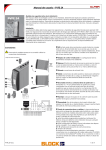
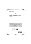
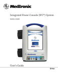
where U is voltage [V], t – pulse width [seconds], C – capacitance of capacitor battery [F], K0 – flashlamp impedance [Ohm A1/2] Some examples are given below. All plots depict the second, capacitor lifetime based, criterion; X‐axis – voltage [V]; Y‐axis – pulse width [milliseconds]. Area allowed with the criterion is in the left‐bottom part of the plot. Capacitance 28 000uF (i.e. VMAX is in range 300V – 450V)
K0 = 10; C = 0.028
K0 = 15; C = 0.028
5
5
4
4
3
3
2
2
1
1
150
200
250
300
350
400
450
150
200
250
300
350
400
450
Maximal voltage based on 1kA current limit is 316V K0 = 20; C = 0.028
K0 = 25; C = 0.028
20
20
17.5
17.5
15
15
12.5
12.5
10
10
7.5
7.5
5
5
2.5
2.5
150
200
250
300
350
400
450
150
K0 = 30; C = 0.028
50
40
40
30
30
20
20
10
10
200
250
300
350
250
300
350
400
450
K0 = 35; C = 0.028
50
150
200
400
450
150
200
250
300
350
400
450
Capacitance 7 000uF (i.e. VMAX is in range 451V – 900V)
K0 = 10; C = 0.007
K0 = 15; C = 0.007
2
2
1.75
1.75
1.5
1.5
1.25
1.25
1
1
0.75
0.75
0.5
0.5
0.25
0.25
200
400
600
800
Maximal voltage based on 1kA current limit is 316V 200
K0 = 20; C = 0.007
3.5
3.5
3
3
2.5
2.5
2
2
1.5
1.5
1
1
0.5
0.5
600
800
Maximal voltage based on 1kA current limit is 632V 200
K0 = 30; C = 0.007
8
8
6
6
4
4
2
2
600
400
600
800
K0 = 35; C = 0.007
10
400
Maximal voltage based on 1kA current limit is 790V 10
200
800
K0 = 25; C = 0.007
4
400
600
Maximal voltage based on 1kA current limit is 474V 4
200
400
800
200
400
600
800
Capacitance 2 500uF (i.e. VMAX is in range 901V – 1350V)
K0 = 10; C = 0.0025
K0 = 15; C = 0.0025
1
1
0.8
0.8
0.6
0.6
0.4
0.4
0.2
0.2
200
400
600
800
1000
1200
Maximal voltage based on 1kA current limit is 316V 200
400
K0 = 20; C = 0.0025
1.75
1.75
1.5
1.5
1.25
1.25
1
1
0.75
0.75
0.5
0.5
0.25
0.25
600
800
1000
1200
Maximal voltage based on 1kA current limit is 632V 200
K0 = 30; C = 0.0025
2.5
2.5
2
2
1.5
1.5
1
1
0.5
0.5
600
800
1000
1200
Maximal voltage based on 1kA current limit is 948V 400
600
800
1000
200
400
600
800
1000
1200
1200
Maximal voltage based on 1kA current limit is 1106V Recommendation: The lower K0 has your flashlamp the lower VMAX should be chosen K0 = 35; C = 0.0025
3
400
1200
Maximal voltage based on 1kA current limit is 790V 3
200
1000
K0 = 25; C = 0.0025
2
400
800
Maximal voltage based on 1kA current limit is 474V 2
200
600
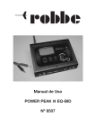
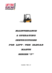
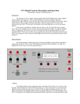
MAXIMAL REPETITION RATE First of all maximal repetition rate is limited with 100 Hz (hardware limit caused with IGBT switching losses) Besides, maximal repetition rate is limited with maximal output power and pulse energy ratio. Also customer must take onto consideration that maximal output power depends on output voltage. Maximal output power is equal to nominal output power in range about 70‐100% of VMAX. At lesser output voltages maximal output power decreases linearly to zero. PêPmax
1
0.8
0.6
0.4
0.2
0.2
0.4
0.6
0.8
1
VêVmax
Recommendation: VMAX should be chosen near real operating voltage. Large gap between operating voltage and VMAX decreases significantly the maximal output power As a result, customer must operate in area limited with the following inequalities: U ≤ 31.6 K0 t ≤ 0.3
C K02
2 U f ≤ 100 Hz f≤
P@ UD
U3 ê K02 t SPECIFICATION (PREDEFINED) ELECTRICAL SPECIFICATION Input: Input voltage Output: Max. voltage (VMAX) Max. current Pulse width Repetition rate Max. output power (WMAX) Discharge: Discharge type Capacitor battery
1 phase, 230 VAC, 50/60 Hz
user defined in 300V‐1350V range
1000 A (see also Current limit section) user defined (see also Maximal pulse energy section) user defined (hardware limit – 100Hz) user defined in 500W‐3500W range
partial discharge
depends on VMAX as:
300V – 450V – capacitance is 28000uF 451V – 900V – capacitance is 7000uF 901V – 1350V – capacitance is 2500uF Triggering: Triggering type Triggering voltage
Triggering pulse energy Simmer supply: Simmer current Max. simmer voltage Open circuit voltage Pockels cell driver
Synchronization
Synchro pulse delay time Hardware protections: Environment: Operation temperature Storage temperature Humidity user defined
about 10 kV
about 100 mJ
about 500 mA (other on request)
200 V
1350 V
optionally
1x synchro output
user defined
from overvoltage,
from overheating, from flashlamp breakdown, fuses 0…+40 C
‐20…+60 C
90%, non‐condensing
MECHANICAL SPECIFICATION Size (LxWxH) Weight 482x306x172 mm
10‐12kg in dependence on WMAX
OVERVIEW FLD is a laser power supply designed for driving of pulsed flashlamp‐pumped solid‐state lasers such as Nd:YAG, Er:YAG, Alexandrite etc. Module contains all necessary to drive standard flashlamp: capacitor charger, simmer supply, capacitor battery, user interface etc. Water cooling system is not included. SAFETY Warning! This equipment produces high voltages that can be very dangerous. Don’t be careless around this equipment •
During operation the protective covers of the equipment must be securely in place and all electrical connections must be properly attached •
Do not operate with disconnected load •
The FLD laser power supply is designed to be properly grounded •
It is the user’s responsibility to ensure that personnel are prevented from accidentally contacting the power supply high voltage connectors and cables. Casual contact could be fatal! •
After shutdown, do not handle the system output until internal capacitor battery has been completely discharged. Use an appropriate meter to check for complete discharge •
Disconnect the power supply from the mains before making or changing electrical or mechanical connections •
Don’t remove protective covers! There are no user serviceable parts inside this equipment. Do not self‐repair the driver •
Do not turn the driver on if it was already damaged with water, chemicals, mechanical or electrical shock SIMPLE USER INTERFACE DESCRIPTION FRONT PANEL DESCRIPTION EMERGENCY
BUTTON
KEY
VOLTAGE
MONITOR
REPETITION
RATE
PULSE WIDTH
VOLTAGE
SYNCHRO
CONNECTOR
EMERGENCY BUTTON – must be released to allow operations. Normally emergency button is used to shut‐down module in the case of some emergency need, for example in the case of the failure KEY – must be turned to the right to allow operations VOLTAGE – group of 4‐digits indicator and two buttons Use this group to set desired output voltage (up to VMAX). PULSE WIDTH – group of 4‐digits indicator and two buttons. Use this group to set desired pulse width (see page 3). REPETITION RATE – group of 4‐digits indicator and two buttons. Use this group to set desired repetition rate (see page 3). VOLTAGE MONITOR – indicates real voltage capacitor battery is charged to SYNCHRO CONNECTOR – provides synchronization output signal for communications with other modules. Synchronization signal may be delayed relatively to start of the flashlamp’s pulse. SIMMER STATUS LED
READY LED
ENABLE button
CHARGING MODULE button
SIMMER SUPPLY button
SYNCHRO button
SIMMER SUPPLY button – starts / stops simmer supply. After SIMMER SUPPLY button is pressed, simmer supply continuously tries to strike flashlamp and establish the simmer discharge. There are two LEDs nearby the SIMMER SUPPLY button. Left one just indicates if SIMMER SUPPLY button is pressed or released. Right one (SIMMER STATUS LED) indicates if the simmer discharge is established at the moment. Normally it takes just a few seconds to establish simmer discharge and light SIMMER STATUS LED. Elsewise something goes wrong. CHARGING MODULE button – starts / stops capacitor charging module. After CHARGING MODULE button is pressed capacitor charging module tries to charge internal capacitor battery up to value selected within VOLTAGE group. There are two LEDs nearby the CHARGING MODULE button. Left one just indicates if CHARGING MODULE button is pressed or released. Right one (READY LED) indicates if capacitors are successfully charged or not at the moment. Normally it takes 2‐3 seconds to charge capacitor battery from zero to Vmax and much less within interpulse interval. Note: if READY LED doesn’t blink between two sequential pulses it means that desired output power (which depends on K0, voltage, pulse width, repetition rate) exceeds maximal output power of the module. ENABLE button – output of the module is disabled till ENABLE button is on. Corresponding LED indicates its status. Note: besides ENABLE button you need to establish simmer discharge, turn the capacitor charging module on and press FOOTSWITCH to get pulse Warning! If FOOTSWITCH is already pressed when you’re pressing ENABLE button module will start operations without any warnings. Be careful! SYNCHRO button – enables / disables output of synchronization signal. Since the same synchro signal controls Pockels cell driver, this button enables / disables high voltage pulses too. BACK PANEL DESCRIPTION MAINS connector (conjugated cable are supplied) – connects module to the mains FLASHLAMP connectors (conjugated cables supplied) – anode connector is marked with “+”, cathode with “‐”. FOOTSWITCH connector (conjugated cable with simple button supplied) – you need to connect to this connector either footswitch or handheld button, or just short‐circuit this connector INTERLOCK connector – you need to connect to this connector some sensors that are allowed to block module’s output, or just short‐circuit this connector FUSES – 2x fuses (rating depends on selected maximal output power) HV OUTPUT connector (conjugated cable supplied) – standard MOLEX MINIFIT connector – the output of embedded Pockels cell driver SYNCHRONIZATION PULSE DELAY SPD‐MODE If you need to change synchronization pulse delay you have to enter SPD‐MODE. To enter this mode please press three button marked with red at the same time (see SPD‐MODE picture). Indicators marked with blue will allow you to change synchronization pulse delay in user‐defined range (see page 3). To return to the main mode please press abovementioned three buttons again. POCKELS CELL DRIVER Module may contain embedded Pockels cell driver (of QBD‐series). See page 3 for Pockels cell driver part number. Parameters of the Pockels cell driver may be set in PCD‐MODE. To enter this mode press two buttons marked with red at the same time (see PCD‐MODE picture). HV MONITOR
HV
HV
ENABLE
PCD‐MODE After entering this mode: HV – use this group to set desired high voltage. HV MONITOR – indicates measured value of high voltage. HV ENABLE – press this button to enable / disable high voltage output of Pockels cell driver. Warning! If you press HV ENABLE button high voltage will be applied at the HV OUTPUT connector. High voltage won’t be removed till you press HV ENABLE button again. Return to the main mode won’t remove high voltage from HV OUTPUT connector! Be careful! To quit PCD‐MODE press two abovementioned buttons again. OPERATIONS (FREE‐RUNNING) 1.
Connect flashlamp to the power supply. 2.
Connect footswitch (or its alternative) to the power supply. 3.
Connect power supply to the mains. 4.
Turn on power supply 5.
Select parameters you wish to obtain on power supply output 6.
Press SIMMER SUPPLY button, wait for SIMMER STATUS LED 7.
Press CHARGING MODULE button, wait for READY LED 8.
Press ENABLE button 9.
Press footswitch. The power supply starts its work. 10.
To turn power supply off press ENABLE, CHARGING MODULE, SIMMER SUPPLY buttons again. Then turn power supply off OPERATIONS (Q‐SWITCHING) 1.
Connect flashlamp to the power supply. Connect Pockels cell to the power supply. 2.
Connect footswitch (or its alternative) to the power supply. 3.
Connect power supply to the mains. 4.
Turn on power supply 5.
Select parameters you wish to obtain on power supply output 6.
Go to PCD‐MODE 7.
Select desired high voltage. Press HV ENABLE button (This action immediately applies high voltage to the Pockels cell. Be careful!). Ensure that HV MONITOR changed its state 8.
Go out from PCD‐MODE 9.
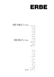
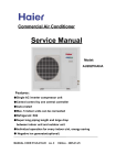
Go to SPD‐MODE. Select desired q‐switched pulse delay. Go out from SPD‐MODE 10. Press SYNCHRO button (q‐switched pulses are impossible without this action) 11. Press SIMMER SUPPLY button, wait for SIMMER STATUS LED 12. Press CHARGING MODULE button, wait for READY LED 13. Press ENABLE button 14. Press footswitch. The power supply starts its work. 15. To turn power supply off press ENABLE, CHARGING MODULE, SIMMER SUPPLY buttons again. Then turn power supply off (no need to turn off Pockels cell driver separately) DRAWINGS ADVANCED USER INTERFACE DESCRIPTION FRONT PANEL DESCRIPTION EMERGENCY BUTTON
MONITOR/TOUCHSCREEN
LED INDICATORS
SYNCHRO OUTPUT
KEY
KEY – it’s power switch of the module. Use KEY to turn module on and off EMERGENCY BUTTON – is used to shut down module in the case of emergency need (for example in the case of the failure). MONITOR/TOUCHSCREEN assembly – no need in comments LED INDICATORS – indicates status of module’s parts (LEDs from the top to the bottom indicate capacitor charging module status, simmer supply status, Pockels cell driver status, STANDBY/READY status correspondingly) SYNCHRO OUTPUT – BNC‐type connector, synchronization output of the system BACK PANEL DESCRIPTION FLASHLAMP POSITIVE
FLASHLAMP NEGATIVE
PCD CONNECTOR
MAINS
CONNECTOR
GROUND
FOOTSWITCH IDC CONNECTOR
CONNECTOR
FUSE (x2)
MAINS CONNECTOR, FUSES, FLASHLAMP POSITIVE, FLASHLAMP NEGATIVE – no need in comments GROUND is the ground stud with M6 thread FOOTSWITCH connector – you may either connect footswitch (hand switch) to this connector or short‐circuit it IDC CONNECTOR – interlock connector, you may either connect sensor (sensors) to this connector or short‐circuit it PCD CONNECTOR – output of Pockels cell driver (if installed) PROGRAM DESCRIPTION The main screen of program (STAND BY) Main parameters window describes three main parameters of working regime. •
Voltage control sets voltage maintained on internal capacitor battery. This voltage together with flashlamp impedance defines intensity of flashlamp pulse. When Capacitors button is pressed at the same time you can observe measured by internal monitor value of voltage. When both values differ significantly be careful – it may be fault symptom. •
Pulse width control. The pulse width adjustment range is user‐defined. •
Repetition rate control. The repetition rate adjustment range is user‐defined. If system contains Pockels cell driver, Q‐Switch window describes parameters of pulse train generated by Q‐Switch driver: •
Voltage control – defines high voltage on Q‐Switch crystal. When High voltage button is pressed at the same time you can observe measured by internal monitor value of high voltage. When both values differ significantly be careful – it may be fault symptom. •
Number of pulses control – number of pulses in pulse train. If Number of pulses parameter is equal to 1 pulse train contain the only pulse. •
First pulse delay control – delay between flashlamp pulse beginning and first pulse of q‐switching •
Interpulse interval control – distance between first and second pulses in pulse train, second and third etc. Capacitors button When Capacitors button is pressed internal capacitor battery will charged to voltage accordingly to the value of Main parameters > Voltage. The charging process may take a few seconds in dependence on internal capacitor battery capacitance. Simmer button When Simmer button is pressed simmer supply embedded in FLD‐4U power supply tries to trigger and establish simmer discharge through the flashlamp. If triggering process fails during 10 seconds the power supply stops triggering process. High voltage button When High voltage button is pressed the high voltage output from q‐switch is enabled. Warning! Since this moment high voltage is present on system output. Be careful! Casual contact may be fatal! Start button When you press Start button the power supply changes its status from Stand by to Ready. After then every pressing on footswitch (fingerswitch) will cause pulse on flashlamp. Warning! Don’t look inside the laser when Start button is pressed. Exit button Exit button finishes program and saves all the presets. Status bar In the bottom of screen you can find the Status bar – a few pictures, that describe status of interlock‐door‐connector, footswitch, simmer and laser power supply mode (STAND BY or READY) correspondingly. The working screen of program (READY) When this screen appeared the system is ready to work. Every pressing on footswitch will cause pulse on flashlamp. Warning! High voltage is present on system outputs. Be careful! Casual contact may be fatal! Warning! Don’t look inside the laser when Start button is pressed. Stop button When you press Stop button the power supply changes its status from Ready to Stand By. Pulse counter window inform you about number of pulses from beginning of session. OPERATIONS Connect power supply to the mains. Connect flashlamp and Pockels cell driver to the power supply. Connect footswitch (fingerswitch) and interlock‐door connector to the power supply. 1.
TURN ON power supply 2.
Select parameters you wish to obtain on power supply output 3.
Press CAPACITORS button, SIMMER button. If necessary press HIGH VOLTAGE button. 4.
Press START button, wait till system will ready to work 5.
Press footswitch (fingerswitch). The power supply starts its work. 6.
To turn power supply off press STOP button, EXIT button. Then TURN power supply OFF 444
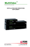
448.2
500
464.82
314.7
DRAWINGS 271
052
9.88
65.14
RS‐232 USER INTERFACE Module is supplied with RS‐232 user interface. D‐SUB 9‐pin connector is located at the back side of the module. Characteristics of RS‐232 interface are given below. RS‐232 connection parameters: 38400 bps, 8 data bit, 1 stop bit, no parity Command format is: {command} {data (optionally)} {end‐of‐line} •
•
•
Command is 1 character long (see list below) Data is ASCII‐string, command and data must be separated with space (space symbol) End‐of‐line symbols are \n or \r\n List of available commands: •
•
•
•
•
•
•
•
v – voltage (V) – sets voltage f – frequency (Hz) – sets frequency p – pulse width (us) – sets pulse width d – synchro delay (us) – sets synchro delay V – returns preset voltage F – returns preset frequency P – returns preset pulse width D – returns preset synchro delay •
•
•
•
•
•
•
•
•
s – simmer enable – starts simmer supply if simmer supply is stopped s – simmer disable – stops simmer supply if simmer supply is started c – ccm enable – starts capacitor charging module if ccm is stopped c – ccm disable – stops capacitor charging module if ccm is started o – start – starts operations o – stop – stops operations S – simmer status – returns simmer supply status (enabled/disabled) C – ccm status – returns capacitor charging module status (enabled/disabled) O – operations status – returns operations status (enabled/disabled) •
•
•
•
1 – simmer sensor – returns status of internal simmer sensor (is on / is off) 2 – ready – returns capacitor charging module status (is ready / not ready)+++ U – voltage monitor – returns internal voltage monitor F – footswitch – returns footswitch status (pressed / released) Example: •
•
run HyperTerminal software type “v 300”, then press ENTER – it must set voltage to 300 V When you use self‐written software don’t forget end‐of‐line and space symbols