1
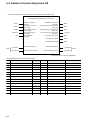
4-1 Memory Assignments
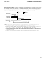
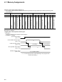
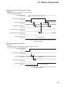
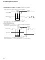
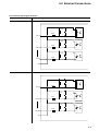
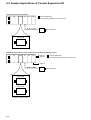
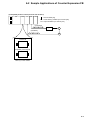
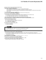
2) Signal name: Current value clear command signal
Description
• Clears the pulse count data register area of the high-speed input module to “0.”
1: Current value clear
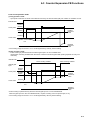
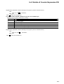
Input mode set signal
“10”: Pulse command + Sign signal
(PLC → PI)
Count enable command signal
(PLC → PI)
“1”
A
A
Pulse count data register
(PLC ← PI)
“0”
A
A
Count operation status signal
(PLC ← PI)
“1”
Current value clear command signal
(PLC → PI)
“1”
A
Current value clear completion signal
(PLC ← PI)
Rotation direction signal
(PLC ← PI)
“1”
“0”: In positive rotation
A: 1 to 2 tacts (The tact time varies depending on the program size
and tact time setting.)
• The response signal for the current value clear command signal is the current value clear completion signal.
• The current value clear command signal can also be cleared during count operation.
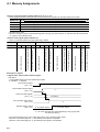
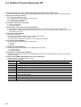
3) Signal name: Input mode set signal
Description
• Set when performing counter operation by the high-speed input module.
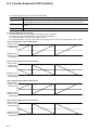
3)-1 90° phase difference pulse
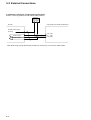
• Set address bits “2,” “3,” “6,” “7,” “10,” “11,” “14” and “15” to “0.” The input specifications are given below.
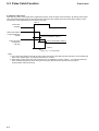
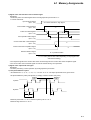
90° phase difference pulse (A-/B-phases, 4-multiply, maximum 80 kHz, duty 50%)
Positive
rotation
Negative
rotation
A-phase
t3
B-phase
t1
t1
t3
t2
Minimum pulse width: t1 > 20 µs, Minimum pulse cycle: t2 > 40 µs
Minimum edge interval: t3 > 20 µs
4-7