1
User's Manual
1
2
Contents
1
Preface .......................................................................................... 4
1.1
Included ......................................................................................... 5
1.2
Transport ....................................................................................... 5
2
Installation ................................................................................... 6
2.1
Installation MAP 1 / MAP V2 ...................................................... 6
2.2
Installation SAM V2 / SAM G2 ................................................... 7
2.2.1
SAM V2 ........................................................................... 8
2.2.2
SAM G2 ........................................................................... 9
2.3
Installation PRE 1 / PRE 1 G2 .................................................... 10
2.4
Installation PRE 1 G3.................................................................. 12
2.5
Installation DNP .......................................................................... 14
2.6
Installation MAP ......................................................................... 15
3
Connecting the analog drive..................................................... 16
4
Setup ........................................................................................... 17
4.1
Jumper settings ............................................................................ 18
4.2
MM pickup systems .................................................................... 19
4.3
MC pickup systems ..................................................................... 19
4.4
Typical setups.............................................................................. 19
4.5
Fine tuning .................................................................................. 20
4.6
Factory defaults ........................................................................... 21
5
Deinstallation ............................................................................. 22
5.1
Deinstallation MAP 1 / MAP V2 ................................................ 22
5.2
Deinstallation SAM V2 / SAM G2 ............................................. 23
5.3
Deinstallation PRE 1 / PRE 1 G2................................................ 23
5.4
Deinstallation PRE 1 G3 ............................................................. 23
5.5
Deinstallation DNP ..................................................................... 24
5.6
Deinstallation MAP..................................................................... 24
6
Security advice........................................................................... 25
7
Technical data ........................................................................... 26
3
1
Preface
The Audionet Team congratulates you on your purchase of the Audionet
Phonomodule.
The module allows you to connect your analog drive ('turntable') to connect directly to your Audionet system without the need of an external
phono pre amplifier.
Despite its compact dimensions, the Phonomodule is very flexible to
adjust to many different pickup systems. The variaty of impedance and
gain settings makes it possible to connect almost any MC or MM pickup.
Electrically and tonally optimized for you Audionet system, the Phonomodule reproduces your records with exciting performance.
But before you start listening to your new Audionet Phonomodule, please
read this manual carefully so you are able to use and enjoy all functions
of this unit without drawback on music quality.
Note
•
The identifiers MAP 1, SAM, PRE 1 and MAP within this manual
represent all versions/generations of the corresponding Audionet
units unless explicitly excluded.
4
1.1 Included
Audionet delivers the Phonomodule to end customers only installed into
an Audionet pre or integrated amplifier (host unit) ready for use.
Tipp
•
While ordering the Phonomodule, let your Audionet dealer know
which pickup system you use. For an optimized adjustment the output voltage of the pickup and the manufacturer recommended values
for input resistance and capacitance are necessary to know. Your
Phonomodule will be configured to these values ready to use.
If the Phonomodule is delivered to authorised and qualified personal, an
assembly kit for mounting the module in the host unit is included.
1.2 Transport
Important
•
Please mind the notes about transportation of the host unit the
Phonomodule is installed in.
•
Please transport a separate Phonomodule only in the included package to prevent damage to the module.
5
2
Installation
Important
•
The installation of the Phonomodule into an Audionet unit (host
unit) is restricted to authorised personal only!
•
Unauthorised opening of an Audionet unit avoids the warranty!
•
Always disconnect any host unit from mains and pull the mains
cord prior to opening.
•
Ease the installation by disconnecting all cables to the host unit.
•
Use only high quality tools to avoid damage to the host unit. In particular use a rugged allen key made of tempered steel to remove the
screws in the top cover. Otherwise you risk damage.
•
Please read the complete installation manual first so you are familiar
with all steps of the installation process.
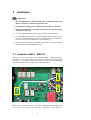
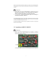
2.1 Installation MAP 1 / MAP V2
Remove all screws of the top cover. Open the MAP 1 / MAP V2 by lifting up the cover. Put the unit in front of you with the front panel facing
towards you. Use picture below to locate the 3 connectors for mounting
the Phonomodule at the rear left side of the main board.
Connectors for mounting the Phonomodule
Remove all 4 jumpers on the 3 connectors. Push the Phonomodule with
its 3 jacks on its bottom side onto the 3 connectors of the MAP 1 /
6
MAP V2 main board until the module sits tight on the mounting bolts.
The alignment of the connectors determine the orientation of the Phonomodule.
Important
•
Please make sure that the Phonomodule is aligned correctly on
the pins of the connectors of the main board of the MAP 1 /
MAP V2. Double check it before you switch on the unit!
•
An incorrectly installed Phonomodule might cause damage to
itself and/or the MAP 1 / MAP V2!
Fix the Phonomodule with 3 screws (M3 x 6 mm) now. In case you setup
the input impedance and the gain of the module correctly for the pickup,
you may re-assemble the top cover now.
If some fine tuning is still necessary to adjust the module to the pickup
then leave the unit open.
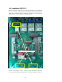
2.2 Installation SAM V2 / SAM G2
Important
•
Before you install the Phonomodule into a SAM V2 / SAM G2,
please check if two 100 pF capacitors are installed in the place
marked in the following picture:
(2x100p for SAM is printed on the PCB right beside the capacitors)
7
•
If both capacitors are missing, as in the picture above, please contact
the Audionet Service Center.
•
If you want to install a Phonomodule originating from a SAM V2 /
SAM G2 into a different type of Audionet unit, please make sure to
remove the capacitors mentioned above prior to installing!
First remove the 3 screws in the lower row of each side panel. Then remove the 3 screws of the top cover right beside the front panel and 3
screws right beside the back panel. After removing the screw in the middle of the ventilation slots you can lift up the cover of the SAM V2 /
SAM G2.Place the unit in front of you with the front panel facing towards you. On the right side of the back panel you can see a board with
all the input relays and input jacks.
2.2.1
SAM V2
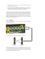
Use the following picture to locate both jumpers. They are on the right
edge of the input board:
Jumpers
Connectors for mounting the Phonomodule
The following picture shows the correct jumper positions:
Jumpers
without
Phonomodule
with
Phonomodule
Push the Phonomodule with its 3 jacks on the bottom side onto the 3 connectors on the input board marked in the picture above until the module
sits tight on the mounting bolts. The orientation of the module is determined by the alignment of the connectors.
8
2.2.2
SAM G2
Please locate the three phono module connectors on the input board of
your SAM G2 like shown in the above chapter „SAM V2“. On these
three connectors you’ll find some blue jumpers which have to be removed before inserting the phono module.
Push the Phonomodule with its three jacks on the bottom side onto the
three connectors on the input board marked in the picture above until the
module sits tight on the mounting bolts. The orientation of the module is
determined by the alignment of the connectors.
Important
•
Please make sure the Phonomodule is aligned correctly on the
pins of the connectors of the input board of the SAM V2 /
SAM G2. Double check it before you switch on the unit.
•
An incorrectly installed Phonomodule might cause damage to
itself and/or the SAM V2 / SAM G2!
Fix the Phonomodule with 2 screws (M3 x 6 mm) now. In case you setup
the input impedance and the gain of the module correctly for the pickup,
you may re-assemble the top cover now.
If some fine tuning is still necessary to adjust the module to the pickup
then leave the unit open.
9
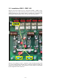
2.3 Installation PRE 1 / PRE 1 G2
Remove all screws of the top cover, and open the PRE 1 / PRE 1 G2 by
lifting up the cover. Place the unit in front of you with the front panel
facing towards you. Use picture below to locate the 3 connectors for
mounting the Phonomodule at the rear left side of the main board.
Connectors for mounting the Phonomodule
Remove all 4 jumpers on the 3 connectors. Push the Phonomodule with
its 3 jacks on the bottom side onto the 3 connectors until the module sits
tight on the mounting bolts. The orientation of the module is determined
by the alignment of the connectors.
10
Important
•
Please make sure the Phonomodule is aligned correctly on the
pins of the connectors of the main board of the PRE 1 /
PRE 1 G2. Double check it before you switch on the unit.
•
An incorrectly installed Phonomodule might cause damage to
itself and/or the PRE 1 / PRE 1 G2!
Fix the Phonomodule with 4 screws (M3 x 6 mm) now. In case you setup
the input impedance and the gain of the module correctly for the pickup,
you may re-assemble the top cover now.
If some fine tuning is still necessary to adjust the module to the pickup
then leave the unit open.
11
2.4 Installation PRE 1 G3
Remove all screws of the top cover, and open the PRE 1 G3 by lifting up
the cover. Place the unit in front of you with the front panel facing towards you. Use picture below to locate the 3 connectors for mounting the
Phonomodule at the rear left side of the main board.
Connectors for mounting the Phonomodule
Remove all 4 jumpers on the 3 connectors. Push the Phonomodule with
its 3 jacks on the bottom side onto the 3 connectors until the module sits
12
tight on the mounting bolts. The orientation of the module is determined
by the alignment of the connectors.
Important
•
Please make sure the Phonomodule is aligned correctly on the
pins of the connectors of the main board of the PRE 1 G3. Double
check it before you switch on the unit.
•
An incorrectly installed Phonomodule might cause damage to
itself and/or the PRE 1 G3!
Fix the Phonomodule with 4 screws (M3 x 6 mm) now. In case you setup
the input impedance and the gain of the module correctly for the pickup,
you may re-assemble the top cover now.
If some fine tuning is still necessary to adjust the module to the pickup
then leave the unit open.
13
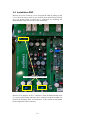
2.5 Installation DNP
Remove all screws of the top cover, and open the DNP by lifting up the
cover. Place the unit in front of you with the front panel facing towards
you. Use picture below to locate the 3 connectors for mounting the
Phonomodule at the rear left side of the main board.
Connectors for mounting the Phonomodule
Remove all 4 jumpers on the 3 connectors. Push the Phonomodule with
its 3 jacks on the bottom side onto the 3 connectors until the module sits
tight on the mounting bolts. The orientation of the module is determined
by the alignment of the connectors.
14
Important
•
Please make sure the Phonomodule is aligned correctly on the
pins of the connectors of the main board of the DNP. Double
check it before you switch on the unit.
•
An incorrectly installed Phonomodule might cause damage to
itself and/or the DNP!
Fix the Phonomodule with 4 screws (M3 x 6 mm) now. In case you setup
the input impedance and the gain of the module correctly for the pickup,
you may re-assemble the top cover now.
If some fine tuning is still necessary to adjust the module to the pickup
then leave the unit open.
2.6 Installation MAP
Important
•
The installation of a Phonomodule into the MAP is done by the
Audionet Service Center only!
15
3
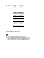
Connecting the analog drive
Connect the outputs Left/Right of your analog drive ('turntable') to the
phono input of your Audionet host unit. Refer to the following table to
find out which input of your host unit is now the dedicated phono input
after installing the Phonomodule:
Host unit
Phono input
MAP 1
Input 2
MAP V2
Input 6
MAP
Input 6
SAM G2
Input 6
SAM V2
Input 1
PRE 1
Input 7
PRE 1 G2
Input 6
PRE 1 G3
Input 6
DNP
Input 5
In most cases an additional grounding of the analog drive is necessary to
avoid humming. The connector for this ground connection is labelled
'GND' and located for most parts close to the phono input. Please consult
the user's manual of your Audionet host unit.
Note
•
Never use force or tools to tighten the ground connection!
•
After installing the Phonomodule the corresponding input of your
host unit is only suitable for playback of signals from an analog drive
('turn table'). Do not connect any line level units to the phono input!
16
4
Setup
Please make sure which type of pickup unit you have and which input
impedance and gain is recommended by the manufacturer. You need this
information to adjust the Phonomodule correctly to the pickup. In case of
doubt treat the pickup as 'MM' system and use the standard settings listed
below.
Section 'Fine tuning' on page 20 offers more detailed information on further adjustments.
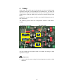
The following picture shows the configuration elements of the Phonomodule:
Input impedance of right channel
Gain of right channel
Gain of left channel
Input impedance of left channel
For each channel several jumper fields are available for setting up input
impedance and gain.
Important
•
Always select the same settings for input impedance and gain on both
channels!
17
4.1 Jumper settings
The jumper fields in center of the module determine the gain. Please refer
to the table below to find the jumper setting for the desired gain. Additionally, the gain is printed on the module right beside the jumper position.
The jumper field for selecting the input impedance is divided into two
separate areas. The first 5 jumper positions (counted from the left) are for
selecting the input resistance, the remaining 4 positions determine the
input capacitance.
Input resistance
Input capacitance
Again, the values are printed on the module right beside the jumper positions. To setup 68 kΩ input resistance please remove the corresponding
jumper.
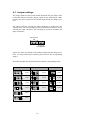
The following table lists all possible position and the corresponding values:
Input resistance
Input capacitance
Gain
68 kΩ
110 pF
38 dB
47 kΩ
160 pF
48 dB
33 kΩ
220 pF
58 dB
2,2 kΩ
330 pF
68 dB
470 Ω
100 Ω
18
4.2 MM pickup systems
For MM pickup systems set the gain to 38 dB, i.e. put the jumper in the
left position (labelled '38' on the Phonomodule, also see table above). For
the settings of input resistance and capacitance please refer to the recommendations of the manufacturer of your pickup.
In case you have no recommendations from the manufacturer for input
resistance and capacitance, set the jumpers to position 47 kΩ and 220 pF.
These settings offer suitable conditions for most MM pickup systems.
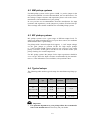
4.3 MC pickup systems
MC pickup systems cover a great range of different output levels. To
achieve an output matching the level of your other sources, the Audionet
Phonomodule offers 3 gain settings:
For pickups with a 'normal' output level (approx. 1...2 mV output voltage)
set the 'gain' jumper to position 58 dB. For high output pickups
(3...5 mV) position 48 dB is better suited. In case you have a low output
pickup (<0.8 mV) set the gain to 68 dB. In case of doubt assume your
pickup working at a 'normal' output level.
For MC pickup systems the jumper for the input capacitance should be
set to 110 pF. Select the input resistance recommended by the manufacturer or, if the information is not available, select position 100 Ω.
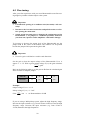
4.4 Typical setups
The following table outlines typical setups for miscellaneous pickup systems:
System
Output voltage
Gain
Input
resistance
Input capacitance
Low Output MC
< 0,6 mV
68 dB
100 Ω
110 pF
MC
~ 1...2 mV
58 dB
~ 3...5 mV
48 dB
100...470 Ω
110 pF
High Output MC
MM
~ 4...6 mV
48 dB
47...68 kΩ
160...220 pF
High Output MM
> 6 mV
38 dB
47...68 kΩ
160...220 pF
Important
•
For optimum adjustment to your pickup follow the recommendations of the manufacturer! If necessary ask your dealer.
19
4.5 Fine tuning
After your first experiences with your new Phonomodule some fine tuning might be possible to further improve the system.
Important
•
Unauthorised opening of an Audionet unit (host units) voids warranty!
•
Disconnect the host unit from mains and pull the mains cord before opening the mains unit.
•
Switch off the host unit prior to changing the configuration of the
Phonomodule (= set jumper to a different position)! Otherwise
your host unit, speakers and/or amplifiers could suffer damage!
To increase or decrease the output level of the Phonomodule use the
jumper field in the center of the module. The numbers 38...68 printed
besides the jumper field represent the gain in dB.
Important
•
Excessive gain could lead to overdrive and distortion!
Set the gain so that the output voltage of the Phonomodule Umodul is
approx. 1...1.5 V. With a given pickup voltage Upickup the gain calculates
U modul
U pickup
to:
= gain .
Refer to the following table to get the gain in dB from the calculated gain
factor in order to setup the jumper:
Gain in dB
38
48
58
68
Gain factor
80
250
800
2500
Example:
Output voltage: Umodul = 1.2 V
Pickup voltage: Upickup = 1.5 mV
Gain:
1.2V
1.5 mV
= 800
⇒ set Phonomodule to 58 dB
If you are using a MM pickup system, adjust the high frequency range:
Increase the input resistance (e.g. from 47 kΩ to 68 kΩ) to boost the high
frequency range. Decrease the input resistance (e.g. from 47 kΩ to
33 kΩ) attenuates the high frequencies.
20
While selecting the input capacitance please keep in mind the capacitance
of the connection cable from the analog drive to the host unit (approx.
100 pF per meter of length). Exceeding capacitances most probably lead
to presence boost and high frequency attenuation.
As described above, the input capacitance is extraneous for MC pickup
systems. Some systems call for a higher input resistance (2,2 kΩ), others
need a much lower setting (100 Ω) for optimum performance. Please
follow the recommendations of the manufacturer of the pickup.
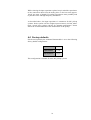
4.6 Factory defaults
If delivered separately the Audionet Phonomodule is set to the following
factory default configuration:
Gain
58 dB
Input resistance
470 Ω
Input capacitance
110 pF
This configuration is suitable for most MC pickup systems.
21
5
Deinstallation
Important
•
The de-installation of a Phonomodule off an Audionet unit (host
unit) is restricted to authorised personal only!
•
Unauthorised opening of an Audionet unit voids warranty!
•
Disconnect the host unit from mains and pull the mains cord
prior to opening.
•
Ease the installation by disconnecting all cables to the host unit.
•
Use only high quality tools to avoid damage to the host unit. In particular use a rugged allen key made of tempered steel to remove the
screws in the top cover. Otherwise you risk damage.
•
Please read the complete installation and de-installation manual first
so you are familiar with all steps of the de-installation process.
5.1 Deinstallation MAP 1 / MAP V2
Open the unit as described in section "Installation MAP 1 / MAP V2" on
page 6. First, remove the 3 screws fixing the Phonomodule. Then pull off
the module. Finally, set all 4 jumpers onto the connectors of the main
board. Refer to the pictures in section "Installation MAP 1 / MAP V2" on
page 6. There you can see the correct position of the jumpers. Additionally, the main board has markings showing you which pins of the connectors to connect with jumpers.
Important
•
If you do not set the 4 jumpers correctly, you cannot use input no. 2
of the MAP 1 or input no. 6 of the MAP V2!
22
5.2 Deinstallation SAM V2 / SAM G2
Open the unit as described in section "Installation SAM V2 / SAM G2" on
page 7. First, remove both screws fixing the Phonomodule. Then pull off
the module. Finally, set the jumpers on the right edge of the input board
according to the picture in section "Installation SAM V2 / SAM G2" on
page 7.
Important
•
If you do not set both jumpers correctly, you cannot use input no. 1 of
the SAM V2 or input no. 6 of the SAM G2!
5.3 Deinstallation PRE 1 / PRE 1 G2
Open the unit as described in section "Installation PRE 1" on page 10.
First, remove the 4 screws fixing the Phonomodule. Then pull off the
module. Finally, set the 4 jumpers on the connectors according to the
picture in section "Installation PRE 1" on page 10. You can see the correct position of the jumpers in the picture. Additionally, the main board
has markings showing you which pins of the connectors to connect with
jumpers.
Important
•
If you do not set the 4 jumpers correctly, you cannot use input no. 7
of the PRE 1 or input no. 6 of the PRE 1 G2!
5.4 Deinstallation PRE 1 G3
Open the unit as described in section "Installation PRE 1 G3" on page 12.
First, remove the 4 screws fixing the Phonomodule. Then pull off the
module. Finally, set the 4 jumpers on the connectors according to the
picture in section "Installation PRE 1 G3" on page 12. You can see the
correct position of the jumpers in the picture. Additionally, the main
board has markings showing you which pins of the connectors to connect
with jumpers.
Important
If you do not set the 4 jumpers correctly, you cannot use input no. 6 of
the PRE 1 G3!
23
5.5 Deinstallation DNP
Open the unit as described in section "Installation DNP" on page 14.
First, remove the 4 screws fixing the Phonomodule. Then pull off the
module. Finally, set the 4 jumpers on the connectors according to the
picture in section "Installation DNP" on page 14. You can see the correct
position of the jumpers in the picture. Additionally, the main board has
markings showing you which pins of the connectors to connect with
jumpers.
Important
If you do not set the 4 jumpers correctly, you cannot use input no. 5 of
the DNP!
5.6 Deinstallation MAP
Important
•
The de-installation of a Phonomodule off the MAP is done by the
Audionet Service Center only!
24
6
Security advice
Important
•
Avoid packaging material, especially plastic bags, coming into children's hands!
•
Store and operate host unit and Phonomodule in a dry room at a reasonable room temperature only!
•
Avoid moisture, any liquids, dirt or small objects getting into the host
unit or Phonomodule!
•
Set up the host unit in a sufficiently ventilated environment!
•
Do not cover the host unit!
•
Do not open the host unit. Unauthorised opening will void warranty!
•
Do not short-circuit the outputs!
•
During connecting or removing the analog drive and/or changing the
configuration of the Phonomodule the host unit has to be switched off
to prevent damage to host unit, amplifier or other connected units.
•
Use dry cloth for cleaning!
•
Installation/de-installation of the Phonomodule is restricted to authorised personal only!
We would like to wish you many exciting listening experiences with your
new Audionet product.
If you still have any questions, do not hesitate to ask your competent
Audionet dealer or contact us directly.
25
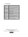
7
Technical data
Function
Stereo phono pre amplifier for MM & MC pickup systems
Circuitry
Two stage active phono equalization according to RIAA
Frequency response
30 Hz – 100,000 Hz (± 0.18 dB)
Gain
38 dB, 48 dB, 58 dB or 68 dB
(configurable by jumper)
Input resistance
100 Ω, 470 Ω, 2,2 kΩ, 33 kΩ, 47 kΩ or 68 kΩ
(configurable by jumper)
Input capacitance
110 pF, 160 pF, 220 pF or 330 pF
(configurable by jumper)
Subsonic filter
2-pole subsonic filter @ 15 Hz with dual servo, without any
capacitor in the signal path
Noise
< -90 dBV (A weighted) @ 48 dB gain (MM)
< -78 dBV (A weighted) @ 58 dB gain (MC)
Connection
Cinch (using Audionet host unit)
Realisation
Plug-in module for Audionet pre and integrated amplifiers (e.g. PRE1, SAM, MAP, MAP1)
Errors and omissions excepted. Specifications and design are subject to changes without prior notice.
audionet is a trademark of Idektron GmbH & Co KG
Engineered and produced by:
Idektron GmbH & Co. KG, Herner Str. 299, Gebäude 6, 44809 Bochum, Germany
www.audionet.de
[email protected]
26