1
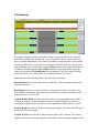
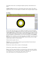
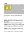
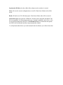
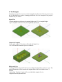
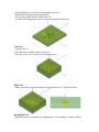
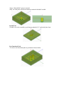
Via Wizard 3.0 User Manual Current as of 7/7/09 Contents Via Wizard 3.0 ....................................................................................................................................... 1 User Manual ......................................................................................................................................... 1 Current as of 6/8/09 .................................................................................................................... 1 1. Revision History ....................................................................................................................... 3 2. Introduction ............................................................................................................................. 4 2.a Quickstart Instructions ...................................................................................................... 4 2.b Basic Program Operation .................................................................................................. 4 3. GUI Parameter Description ..................................................................................................... 5 3.a Stackup .............................................................................................................................. 5 2.b Padstacks ........................................................................................................................... 6 2.c Vias ......................................................................................................................................... 7 2.d Options .............................................................................................................................. 9 2.e Buttons Common to All Tabs ........................................................................................... 10 3. Design Conventions ................................................................... Error! Bookmark not defined. 4. Via Designs ............................................................................................................................. 12 5. Advanced Usage ........................................................................ Error! Bookmark not defined. 5.a Techniques ........................................................................... Error! Bookmark not defined. 5.b Included Variables ............................................................... Error! Bookmark not defined. 5.c Uninstalling .......................................................................... Error! Bookmark not defined. 6. Known Issues ............................................................................. Error! Bookmark not defined. 7. Future Improvements ................................................................ Error! Bookmark not defined. 1. Revision History Many edits have been made to the wizard functionality since version 2.0. The latest wizard has been tested and optimized for HFSS v12. The manual has been updated to reflect the new usage. Some of the major edits are listed below: • Automatically disable/re-enable autosave • Handle units other than mils • Options for sweep setup • Changed Input file format • Additional port scenarios • Removed some unnecessary parameters • Fixed issue with GSSG stackup • Allow 100% via fill • Allow faceted structures • Fixed issue with top/bot planes needing to be solid • Updated solution settings for HFSS v12 • Add variable to control all antipads per via • Added ability to change material properties • Using frequency dependent Dielectric models • Fixed overall project sizing issues • Fixed coax sheath size issues • Coax sheath is now grounded automatically • Added GUI options for backdrilling • Added options for automatically deembedding • Added option for circular anitpads on differential vias • Added options for mesh operations • Added option to use a single block of dielectric • Greyed out don’t care fields of via array inputs • Added graphics for padstack cross-section • Added graphics for via array footprint. 2. Introduction The Via Wizard has been developed to simplify project creation in HFSS v12. Using a straight-forward GUI, a user can enter all parameters necessary to create an arbitrary via array. Most projects will be launched ready to solve in HFSS however the user may easily modify or add to the geometry created by the wizard. Many variable parameters have been added to the project so the user can easily perform parametric analysis. Please refer to the ‘Examples’ folder in the Via Wizard installation directory for some saved examples of common setups. Although every effort has been made to ensure accurate projects, the user should verify everything is setup as intended. The Via Wizard is available free of change and may be distributed without a license. Updates will be made available as appropriate and may be downloaded from 3DViaDesign.com or Ansoft.com/ots. 2.a Quickstart Instructions 1. Launch “Via Wizard GUI.exe.” 2. Fill in the desired information for each of the tabs: Stackup, Padstack, Via, Options. 3. Click “Generate Project.” 4. Typical Via projects are now ready to solve. 2.b Basic Program Operation The Via Wizard consists of two parts: The “Via Wizard GUI.exe” and “HFSS_via_wizard.exe.” The GUI will accept user inputs that describe everything necessary to create an arbitrary via array. After all of the information has been entered, the GUI will generate a text file called “TempFile.txt” that is input into HFSS_via_wizard.exe.” This program will then parse the data and generate a VBscript called “HFSS.vbs” that can be read directly into HFSS. Please refer to the “TempFile_format_3.0.xls” for information on the temp file format. 3. GUI Parameter Description There are three tabs for the GUI used to describe all parameters necessary for the via array. Each of the input parameters is described below: 3.a Stackup The default project contains 4 Layers. Additional layers can be added to the bottom of the stackup using the ADD button on the right. Bottom layers can be removed using the Delete button on the right. Type describes the layer type for the stackup. The stackup always alternates between Metal and Dielectric. The top and bottom layers are always Metal Material describes the material properties that will be used in HFSS. By default Copper is used for Metal layers and FR4 is used for Dielectric layers. To change the material on a particular layer, select it from the pull down menu. Different dielectrics can be added to the pull down menu by using the substrate editor to the right Thickness describes the layer thickness in mils. The default stackup uses 1-oz copper with 5 mil dielectric. Layer Type describes which layers are signals and which layers contain planes. To change the type, select it from the pull down menu. A valid project must contain at least one plane. Substrate Editor is used to add and edit dielectric materials. User specifies Er, TanD and measurement frequency. When The HFSS model is created a frequency dependent Djordjevic-Sarkar dielectric model will be added to the project using the Er and TanD as a name 2.b Padstacks The padstack display changes based on the number of layers defined. For each Metal layer that is defined in the Stackup tab, a row is inserted for the vias. Each of the rows may be defined independent of each other. By default, two padstacks have been defined. Choose the padstack you would like to edit using the Padstack Pull Down Menu on the right. Padstacks can be renamed by using the Rename button on the right. Padstacks may be added or deleted using the Add and Delete buttons on the right. In the lower right corner you can define the Plating Ratio for each padstack. This is the ratio of Plating Metal to Drill Size. The default value is 0.2 and must be between 0 and 1. Layer describes the metal layer that is described by the padstack. Barrel Radius describes the radius of the via drill hole. This is maximum radius of the plated through hole. Pad Radius describes the pads on each layer. By default the radius is set equal to the Barrel Radius indicating no pad exists on the internal layers. On the external layers the default pad size is set to 12 mils. Antipad Radius/Width describes either the radius of circular antipads or the width of rectangular antipads. Circular antipads are drawn if Antipad Height is 0, otherwise a rectangular antipad is drawn. By default circular antipads are defined that are 16 mils. Antipad Height describes the height of rectangular antipads. This value should be set to 0 to describe circular antipads. Antipad X Offset describes the x offset from the center of the via barrel. This offset is applied to the center of circular antipads or the middle of the rectangular antipad’s width. The default for this value is 0, meaning the antipad is perfectly centered about the via barrel. Antipad Y Offset describes the y offset from the center of the via barrel. This offset is applied to the center of circular antipads or the middle of the rectangular antipad’s height. 2.c Vias The Vias tab is where the array of vias is defined. Any number of vias can be added to the project by clicking the Add button on the right. You may delete the last via added by using the Delete button. If you like to delete a via other than the last one added, select the via by clicking on the number in the leftmost column and click Delete. If some vias have been paired together as a differential pair, you can color code them by clicking Identify Diff Vias. If you would like to remove the color coding, select B_W. You can convert all differential vias to single ended by clicking All SE. You must convert all vias to single ended in order to delete a via from the array. Via describes the number of the via. Padstack is a list of all available padstacks as previously defined. Select the desired padstack from the pull down menu. X Loc is the x location of the via center on a Cartesian plane. Y Loc is the x location of the via center on a Cartesian plane. Ports is a pull down menu which allows you select the type of port associated with that via. Choices are None, Trace in/Trace out, and Coax_Launch_Top, Trace_In/None_Out, Trace Out/None_In, Coax_Launch_Bot, Coax_Launch_Top/None_out, Coax_launch_Bot/None_out, Ground and Coax_In/Coax_out None only places a via and does not attach a port. Use this selection for Ground vias or unconnected signal vias. Trace in-Trace out draws two traces that connect to the via. Traces are always drawn in the +/- X direction. The trace into the via goes from the highest X extents of the project to the via. The trace out of the via goes from the via to the lowest X extents of the project. Wave ports are used as excitations. Coax Launch Top draws a coax launch from the top of the project into the via. This is similar to a press-fit connector. A trace is also drawn out of the via escaping to the lowest X extents of the project. Wave ports are used for excitations. Trace in / None Out only draws the trace in. It is assumed the user will manually add the escape. Trace Out / None In only draws the trace out. It is assumed the user will manually add the escape. Coax Launch Bot draws a coax launch from the bottom of the structure as well as a trace escaping in the X direction Coax Launch Top / None Out draws a coax launch from the top but no trace escaping the via. It is assumed the user will manually add the escape. Coax Launch Bot / None Out draws a coax launch from the bottom but no trace escaping the via. It is assumed the user will manually add the escape. Ground this setting assigns no ports to the via but rather is used for grounding the coax sheath during coax launches. All vias specified as ground will be shorted together using a PEC sheet and connected to the outer sheath of the launching coaxes. This setting is the same as None if no coax launches are specified. Coax In / Coax Out draws a coax launches from the top and bottom of the same via. This launch is useful when evaluating via performance independent of traces. Trace In Layer defines the layer the trace is drawn coming into the via. Only signal layers are displayed in the pull down menu. Trace Out Layer defines the layer the trace is drawn escaping from via. Only signal layers are displayed in the pull down menu. Trace In Width defines the nominal width of the trace into the via. Traces are drawn as trapezoids to capture over etching. The value defined here is used as the base of the trapezoid with the top oriented upward. Trace Out Width defines the nominal width of the trace escaping the via. Traces are drawn as trapezoids to capture over etching. The value defined here is used as the base of the trapezoid with the top oriented downward. Diff Pair defines which vias are paired together. Pairing vias together will draw an antipad that surrounds both vias and also link the escape routing together. For more details, please refer to Differential Vias in the Via Designs section. 2.d Options In the Options tab different settings can be applied to the creation of the HFSS project. The different options include General Options, Model Options and Solve Options. Units use a pull down menu to specify the units of the project Solve Project will automatically start the HFSS simulation if this box is checked. Run HFSS will automatically launch and create the project if this box is checked Facets controls the number of facets to apply to all cylindrical structures. 0 facets will create a true cylinder. Model Resolution will create a model resolution mesh operation on all vias with the length specified by the user. If the length is 0 no mesh operation will be applied. De-embedding User may choose, Automatic, None, or Specified. If automatic is selected, the wizard will attempt to set the de-embedding length to be the distance from the port to the start of the antipad on the adjacent plane. None will leave the ports not de-embedded. Specified will activate an new field in which the user can specify the de-embedding distance. Backdrilling if this is checked a variable will be added to the HFSS project that will backdrill the bottom of all vias that have a port attached to them. The length of the backdrill depth will be set using the user specified field Etchback % is the percentage of metal thickness that is removed from the top or bottom of the trace. 0% will produce a rectangular trace while 1%-200% will create trapezoidal traces. W1 = Width – Etchback% * Thickness Include Dogbone will create an oblong antipad for differential vias. If this is unchecked the differential antipads will be determined by the individual vias antipads. Block Dielectric will create a single box for all dielectric rather than individual layers. Material properties are chosen based on Layer1 Dielectric. This can be helpful to optimize speed if simulating a PCB with many layers. Sweep Type allows the user to specify Discrete or Interpolating for the sweep that is created in HFSS. Specify Risetime will automatically compute the max frequency necessary to resolve the risetime specified. Bandwidth is computed based on the knee frequency ~ .35/Tr. Start Frequency is the minimum frequency specified in the HFSS sweep Stop Frequency is the maximum frequency specified for the HFSS sweep as well as the mesh frequency Freq Step is the interval between frequencies solved by HFSS Delta S is the maximum allowable change in computed S parameters between adaptive passes. If the computed s-parameters change more than the allowed Delta S, HFSS continues to adaptively mesh. Max Pass will limit the total adaptive passes HFSS is allowed if the target Delta S is not achieved. 2.e Buttons Common to All Tabs Some buttons are available for use on each of the tabs. Fit to Width scales the columns to match the width of the GUI window. Synchronize Width scales the width of the columns are the window is resized. Store will save the current configuration as a text file. Data from all three tabs will be saved. Read will load a saved Via Wizard project. Data from all three tabs will be restored. Generate Project will create the “HFSS.vbs” file that can be imported into HFSS. The file is saved in the Via Wizard project directory. To load it manually, select Tools->Run Script in HFSS and point to this file. If the Run HFSS button is checked in the options tab, HFSS will be launched and the script automatically loaded. ? is a help button that directs you to this manual and also informs you of the release date. 4. Via Designs Just about any type of via or array can be designed using the wizard. For any exotic cases, the Via Wizard may be used as a starting point. Below are a few examples of via projects and how they are created Signal Vias -Circular antipads can be drawn by entering Radius and “0” for Antipad Height -Square antipads can be drawn by entering Width and Height Connector Footprint -Define pitch using X, Y locations of Ground and Signal vias -Use Coax launch to emulate a press fit connector Differential Vias -Defining Diff Pairs in the GUI will create an elliptical antipad between the two vias. The antipad dimensions will be based on the antipad radius of the via with the lowest Y location. -Unchecking “Dogbone” option will create individual antipads for vias -Dogbone has been parameterized -Set pad/antipad to 0 if you don’t want dogbone on layers -Differential routing has been parameterized -Trace spacing based on trace width of first via -Location of meeting point for traces based on the antipad of that layer. Stub Vias -Typical PTH via -Enter the same via Barrel radius on all layers. -Enter trace out or trace in layer to be an internal layer Blind Vias -Blind vias can be created by entering a barrel thickness of “0” on the null layers. Backdrilled Vias -Backdrilling can be investigated by changing the “Via#_backdrill” variable in HFSS -Ensure “Backdrilled” option is checked -Only vias with ports associated with them contain the backdrill variable Ground Vias -Ground vias can be created by specifying an antipad of “0” on desired plane layer Non-Functional Pads -To remove non-functional pads set pad radius to barrel radius 易迪拓培训 专注于微波、射频、天线设计人才的培养 网址:http://www.edatop.com HFSS视 频 培 训 课 程 推 荐 HFSS 软件是当前最流行的微波无源器件和天线设计软件,易迪拓培训(www.edatop.com)是国内 最专业的微波、射频和天线设计培训机构。 为帮助工程师能够更好、更快地学习掌握 HFSS 的设计应用,易迪拓培训特邀李明洋老师主讲了 多套 HFSS 视频培训课程。李明洋老师具有丰富的工程设计经验,曾编著出版了《HFSS 电磁仿真设计 应用详解》、 《HFSS 天线设计》等多本 HFSS 专业图书。视频课程,专家讲解,直观易学,是您学习 HFSS 的最佳选择。 HFSS 学习培训课程套装 该套课程套装包含了本站全部 HFSS 培训课程,是迄今国内最全面、最 专业的 HFSS 培训教程套装,可以帮助您从零开始, 全面深入学习 HFSS 的各项功能和在多个方面的工程应用。购买套装,更可超值赠送 3 个月 免费学习答疑,随时解答您学习过程中遇到的棘手问题,让您的 HFSS 学习更加轻松顺畅… 课程网址:http://www.edatop.com/peixun/hfss/11.html HFSS 天线设计培训课程套装 套装包含 6 门视频课程和 1 本图书,课程从基础讲起,内容由浅入深, 理论介绍和实际操作讲解相结合,全面系统的讲解了 HFSS 天线设计 的全过程。是国内最全面、最专业的 HFSS 天线设计课程,可以帮助 您快速学习掌握如何使用 HFSS 设计天线,让天线设计不再难… 课程网址:http://www.edatop.com/peixun/hfss/122.html 更多 HFSS 视频培训课程: 两周学会 HFSS —— 中文视频培训课程 课程从零讲起,通过两周的课程学习,可以帮助您快速入门、自学掌握 HFSS,是 HFSS 初学者 的最好课程,网址:http://www.edatop.com/peixun/hfss/1.html HFSS 微波器件仿真设计实例 —— 中文视频教程 HFSS 进阶培训课程,通过十个 HFSS 仿真设计实例,带您更深入学习 HFSS 的实际应用,掌握 HFSS 高级设置和应用技巧,网址:http://www.edatop.com/peixun/hfss/3.html HFSS 天线设计入门 —— 中文视频教程 HFSS 是天线设计的王者,该教程全面解析了天线的基础知识、HFSS 天线设计流程和详细操作设 置,让 HFSS 天线设计不再难,网址:http://www.edatop.com/peixun/hfss/4.html 更多 HFSS 培训课程,敬请浏览:http://www.edatop.com/peixun/hfss ` 易迪拓培训 专注于微波、射频、天线设计人才的培养 网址:http://www.edatop.com 关于易迪拓培训: 易迪拓培训(www.edatop.com)由数名来自于研发第一线的资深工程师发起成立,一直致力和专注 于微波、射频、天线设计研发人才的培养;后于 2006 年整合合并微波 EDA 网(www.mweda.com), 现已发展成为国内最大的微波射频和天线设计人才培养基地,成功推出多套微波射频以及天线设计相 关培训课程和 ADS、HFSS 等专业软件使用培训课程,广受客户好评;并先后与人民邮电出版社、电 子工业出版社合作出版了多本专业图书,帮助数万名工程师提升了专业技术能力。客户遍布中兴通讯、 研通高频、埃威航电、国人通信等多家国内知名公司,以及台湾工业技术研究院、永业科技、全一电 子等多家台湾地区企业。 我们的课程优势: ※ 成立于 2004 年,10 多年丰富的行业经验 ※ 一直专注于微波射频和天线设计工程师的培养,更了解该行业对人才的要求 ※ 视频课程、既能达到现场培训的效果,又能免除您舟车劳顿的辛苦,学习工作两不误 ※ 经验丰富的一线资深工程师讲授,结合实际工程案例,直观、实用、易学 联系我们: ※ 易迪拓培训官网:http://www.edatop.com ※ 微波 EDA 网:http://www.mweda.com ※ 官方淘宝店:http://shop36920890.taobao.com 易迪拓培训 专注于微波、射频、天线设计人才的培养 官方网址:http://www.edatop.com 淘宝网店:http://shop36920890.taobao.com