1
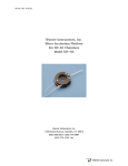
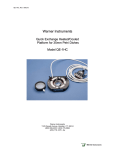
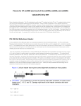
BLM-TC Manual, Rev. 060331
Warner Instruments
Planar Lipid Bilayer Thermocycler
Model BLM-TC
Warner Instruments
1125 Dixwell Avenue, Hamden, CT 06514
(800) 599-4203 / (203) 776-0664
(203) 776-1278 - fax
Warner Instruments
BLM-TC Manual, Rev. 060331
Table of Contents
INTRODUCTION....................................................................................................................................... 5
NOMENCLATURE.................................................................................................................................... 4
Text conventions ..................................................................................................................................... 4
INTRODUCTION....................................................................................................................................... 5
SETUP.......................................................................................................................................................... 6
General procedure.................................................................................................................................. 6
Step 1: CL-100 placement...................................................................................................................... 6
Step 2: Water pump assembly placement ............................................................................................ 6
Step 3: Peltier platform placement ....................................................................................................... 7
Step 4: Warer jacket decoupler placement .......................................................................................... 7
Step 5: Connecting the water lines........................................................................................................ 7
Step 6: Loading the pump reservoir and checking flow ..................................................................... 8
OPERATION .............................................................................................................................................. 9
CL-100 bipolar temperature controller................................................................................................ 9
BCH-M13 / BCH-M22 bilayer chamber ............................................................................................. 9
Cup cap.................................................................................................................................................... 9
Warranty and service........................................................................................................................... 10
Warranty............................................................................................................................................. 10
CL-100 Service notes ......................................................................................................................... 10
Warner Instruments
BLM-TC Manual, Rev. 060331
3
The BLM-TC Planar Lipid Bilayer Thermocycler from Warner Instruments is a versatile and simple to use
thermal control device. This unique device uses Peltier technology to provide both heating and cooling to a
planar lipid bilayer membrane. Total automatic control of heating/cooling power is provided by a Warner
CL-100 Bipolar Temperature Controller.
Features of the BLM-TC include
9 Optimized specifically for use on planar lipid bilayer studies
9 Peltier driven technology
9 Heats and cools
9 Quiet operation - does not interfere with single channel recording
9 Automatic and manual modes
9 Simultaneous monitoring of system temperature and separate point of interest
THIS EQUIPMENT IS NOT DESIGNED NOR INTENDED
FOR USE ON HUMAN SUBJECTS
Warner Instruments
BLM-TC Manual, Rev. 060331
4
NOMENCLATURE
Text conventions
This manual refers to controls at two functional levels; specific controls and settings of these controls.
To minimize the potential for confusion, we have employed several text conventions which are specified
below. Since our goal is to provide clarity rather than complexity, we welcome any feedback you may wish to
provide.
¾ Warner Instrument product numbers are presented using bold type.
¾ References to components are specified using SMALL CAPS.
¾ References to control settings are specified using italic type.
¾ Special comments and warnings are presented in highlighted text.
Any other formatting should be apparent from context.
Warner Instruments
BLM-TC Manual, Rev. 060331
5
INTRODUCTION
The BLM-TC is a Peltier driven thermocycler specifically designed for use with Warner’s Planar Lipid
Bilayer Workstation. A complete thermocycler system is comprised of 4 major components: a special
BILAYER CHAMBER, the PELTIER PLATFORM, a BIPOLAR TEMPERATURE CONTROLLER, and a pump-driven
PLATFORM COOLING SYSTEM.
Actual temperature control (both heating and cooling) is provided by a thermoelectric device embedded
within the PELTIER PLATFORM. Heat energy is added or removed from the solution surrounding the bilayer
membrane by a thermally conductive material inserted into the body of a special bilayer chamber (the
BCH-13M or BCH-M22 chambers). These chambers, in turn, are heated or cooled via a tight physical coupling
between the chamber and the PELTIER PLATFORM.
While the temperature of the PELTIER PLATFORM is set by the BIPOLAR TEMPERATURE CONTROLLER
(Warner model CL-100), excess heat is removed from the platform by a pump-driven circulating water bath.
This cooling system is provided only as a means to keep the associated Peltier device within its thermal
operating limits. A great deal of effort has been dedicated towards making the pump drive both mechanically
and electrically quiet.
Warner Instruments
6
BLM-TC Manual, Rev. 060331
SETUP
Begin by taking assessment of the supplied components. These include the PELTIER PLATFORM, a
WATER PUMP ASSEMBLY, a WATER JACKET DECOUPLER, a CL-100 BIPOLAR TEMPERATURE CONTROLLER, 25
feet of Tygon tubing, and a power strip. Additional components you should have on hand are the BCH-M13
or BCH-M22 chamber along with its CUP CAP, and a bilayer cup. These items are shown below.
General procedure
The general setup procedure is to install the CL-100 into your equipment rack, place the WATER PUMP
near the setup, position the PELTIER PLATFORM in the cage, connect the WATER JACKET
DECOUPLER to the cage wall, and to make necessary connections between components.
ASSEMBLY
Step 1: CL-100 placement
The first step is to install the CL-100 into your equipment rack or other convenient location. The
PELTIER PLATFORM within the Faraday cage will eventually connect to the CL-100 via its connecting cable.
Make all necessary ground and power connections at this time (see CL-100 User’s Manual) but do not power
the instrument.
Step 2: Water pump assembly placement
Next position the WATER PUMP ASSEMBLY at a convenient location near the CL-100 and Faraday cage.
While one option is on the floor below the bilayer setup, bear in mind that the lift capability of the pump is
Warner Instruments
7
BLM-TC Manual, Rev. 060331
limited to 1 m (3 feet). The WATER PUMP ASSEMBLY will eventually connect to the WATER JACKET
on the back of the Faraday cage via the supplied Tygon tubing. Plug the water pump assembly
into the supplied power strip but do not power the device at this time. NOTE: Do not fill the water pump
DECOUPLER
assembly with water at this time.
Step 3: Peltier platform placement
Place the PELTIER PLATFORM within your Faraday cage and run the controller cable out through the
Faraday cage access port to the rear of the CL-100. Make a connection between the PELTIER PLATFORM and
the CL-100.
The PELTIER PLATFORM is supplied with a ground cable attached to it. Make a connection from the
PELTIER PLATFORM to the common ground within your Faraday cage..
Step 4: Warer jacket decoupler placement
The WATER JACKET DECOUPLER attaches to the side wall of your Faraday cage at the access port and
provides grounding of the water lines entering the cage. The DECOUPLER attaches to the cage wall via a
set-screw which pierces the cage material providing a ground connection at that point.
Place the WATER JACKET DECOUPLER onto one side of the access port on the rear of the cage and
tighten it into place using the supplied Allen wrench.
The DECOUPLER is symmetric in design and can be attached from either the inside or the outside of
the cage.
NOTE:
Step 5: Connecting the water lines
Water lines run in a circular path from the PUMP ASSEMBLY to the DECOUPLER to the PELTIER
and back again.
PLATFORM
Begin by running a short length of Tygon tubing from each attachment port on the rear of the PELTIER
to the inside attachment ports on the WATER JACKET DECOUPLER.
PLATFORM
Warner Instruments
8
BLM-TC Manual, Rev. 060331
Next run a pair of water lines from the external attachment ports on the DECOUPLER to the top of the
pump assembly. Make sure all connections are secure - avoid leaks!
You may bundle the water lines enroute to the pump
so as to facilitate an orderly setup. While 25 feet of Tygon
tubing is supplied with the BLM-TC, do not place the PUMP
ASSEMBLY more than 10 feet away from the cage as this can
place undue strain on the pump.
NOTES:
Step 6: Loading the pump reservoir and checking
flow
Verify that the PUMP ASSEMBLY is unplugged. Open the
reservoir by removing the cap on the reservoir top. Fill the
reservoir with clean water up to the bottom of the handle.
Make sure the pump body is completely submerged,
but do not close the top of the reservoir at this time.
NOTE:
Verify that all flow lines between the PUMP ASSEMBLY
and PELTIER PLATFORM are secure and plug the pump into the supplied power strip. Turn the power strip on
to activate the pumping action.
It is likely that on first use the pump will need to be primed. This need will be apparent by (1) a lack of
fluid flow in the lines, and (2) a lot of noise coming from the pump. If the pump needs priming, gently shake
the submerged pump in the reservoir to remove any trapped air from the pump body. Proper filling of the
pump with water will result in its quiet operation.
Once fluid is flowing and all lines are filled, check for leaks and top off the reservoir (to the bottom of
the handle) before sealing the reservoir cap. The system is now ready for use.
Warner Instruments
BLM-TC Manual, Rev. 060331
9
OPERATION
CL-100 bipolar temperature controller
Temperature control of the BLM-TC is maintained by the CL-100. Please review the user’s manual for
this instrument for its operation. All aspects of the CL-100 function are compatible with the BLM-TC. This
includes use of the T2 MONITOR THERMISITOR.
CAUTION ! - While the CL-100 provides control over the Peltier device within the platform, it is the
cooling action of the water jacket which prevents failure, or even destruction, of the Peltier device during
use. Therefore, it is absolutely imperative that the pump be running AT ALL TIMES while power is applied to
the PELTIER PLATFORM. This condition remains true regardless if the device is being used for heating or for
cooling.
BCH-M13 / BCH-M22 bilayer chamber
While much attention in this manual has focused on the Peltier component and it’s cooling system, the
heart of the device resides within the bilayer chamber. Warner offers thermocycler bilayer chambers in two
sizes, 1 ml (BCH-M13) and 3 ml (BCH-M22). These chambers have a thermally conducting assembly attached
to their body which serve to transfer heat from the PELTIER PLATFORM to the solution surrounding the
bilayer membrane.
Begin by preparing and loading your bilayer cup in the usual manner. Place the cup into the BCH-XXM
chamber and prepare the chamber for use as you would normally. Place the cup/chamber assembly into the
PELTIER PLATFORM and make any necessary attachments to the headstage. You may also place and adjust any
stirbars you will use at this time.
Once a stable membrane has formed, temperature control may be applied via the CL-100. As always,
verify that the pump is supplying water to the PELTIER PLATFORM before supplying power to the PELTIER
PLATFORM!
The rate of thermal transfer to the bilayer cup and chamber is on the order of 3-5 °C/min. The actual
temperature within the either the cup or chamber can be directly measured using the supplied T2 MONITOR
THERMISTOR.
Cup cap
A performance difficulty is revealed whenever the BLM-TC is used for cooling of a bilayer membrane. In
a word: condensation.
In general, condensation occurs whenever the temperature of an object goes below the ambient dew
point. In a bilayer environment, the effect of condensation is to provide an undesirable conducting pathway
connecting the cis and trans sides of the bilayer membrane. This is most often revealed as a highly variable,
large-scale offset current which is sudden in onset.
Since the BLM-TC is designed as a thermocycler, we have provided CUP CAPS which can be placed on the
top of the bilayer cup before the beginning of the experiment. A small slot, with PE tubing, is provided in the
CUP CAP to allow access of the silver wire electrode.
NOTE:
Place the CUP CAP on the cup before the occurrence of condensation or its protection will be
mitigated.
Warner Instruments
10
BLM-TC Manual, Rev. 060331
Warranty and service
Warranty
The model BLM-TC is covered by our Warranty to be free from defects in materials and
workmanship for a period of one year from the date of shipment. If a failure occurs within this period,
we will either repair or replace the faulty component(s). This warranty does not cover instrument failure
or damage caused by physical abuse, electrical stress (inputs exceeding specified limits), or pump failure.
In the event that instrument repairs are necessary, shipping charges to the factory are the
customer's responsibility. Return charges will be paid by Warner Instruments, Inc.
Normal business hours are 8:30 AM to 5:30 PM (EST), Monday through Thursday and 8:30 AM to
5:00 PM on Friday. Our offices are located at 1125 Dixwell Avenue, Hamden, CT 06514, and we can be
reached by phone at (800) 599-4203 or (203) 776-0664. Our fax number is (203) 776-1278.
In addition, we can be reached by e-mail at [email protected] or through our Web page
at http://www.warneronline.com.
CL-100 Service notes
Please refer all questions regarding service to our Engineering Department.
A) If the instrument POWER light fails to light, check the fuse at the rear panel (located in the black
POWER INPUT MODULE). If the fuse is found to be defective replace it with a 5x20 mm, 0.5 A slowblow fuse (0.25 A for facilities using 220-240 V line voltages). If the replacement fuse also fails,
please call Warner Instruments for assistance.
B) Occasionally, a knob on the front panel will loosen after long use. These are "collet" style knobs and
are tightened with a screw located under the knob cap. To gain access to the adjustment screw, pry
the cap off with a thin bladed screwdriver or similar tool.
C) Should service be required, please contact the factory. The problem may often be corrected by our
shipping a replacement part. Factory service, if required will be expedited to minimize the customer
inconvenience.
D) Instruments are inspected immediately upon receipt and the customer is notified if the repair is not
covered by the warranty. Repairs can often be completed in 1-2 days from our receipt of the
instrument.
E) If factory service is required, please observe the following instructions:
1) Package the instrument with at least 3 inches of cushioning on all sides. Use the original
shipping carton if it is available.
2) Insure the shipment for its full value.
3) Include with the shipment an explanation of the problem experienced.
Please be sure to contact us before return shipping any
goods. We will provide instructions so that the shipment will not be delayed or subject to unnecessary
expense in clearing U.S. Customs.
IMPORTANT - CUSTOMERS OUTSIDE OF THE U.S.:
Warner Instruments