1
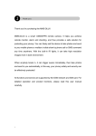
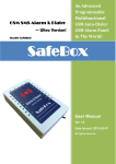
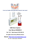
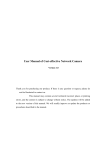
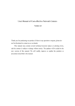
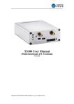
Wireless Alarm GSM Alarm System WASMS-PRO User Manual Ver 1.2 Date Issued: 2008-04-18 All rights reserved by Wireless Alarm. 012-6547895, 012-654 6209 Table of contents 1. 2. 3. 4. 5. 6. 7. 8. 9. 10. 11. 12. 13. 14. Brief introduction -----------------------------------2 Standard Packing list ------------------------------2 Physical Layout -------------------------------------3 Functions and Features ---------------------------3 Installation --------------------------------------------4 Menu Functions -------------------------------------8 Keyboard Instructions ----------------------------13 Menu Operations-----------------------------------14 Remote Control Instructions---------------------23 Add/Cancel wireless sensors--------------------25 Technical specifications --------------------------29 Important information -----------------------------29 Maintenance-----------------------------------------30 Quality Warranty -----------------------------------30 1. Brief introduction The WASMS-PRO is designed for house and office and other applications. It is based on GSM Communication network and LCD Menu display technology. When any sensor triggered, it will Call&Send SMS to user cell phones. Also, the Child Remote Control recognize function is our unique technology, When the Child press his remote control button, the Control Unit will send a SMS “I have left the house” or “I have gone home” to his father or mother! The WASMS-PRO equips with LCD and Operation Menu Display, all operations and settings are visual and intuitive! What you need is a pre-paid or contract SIMCard which support Call ID function. Service providers in South Africa are recommended. 2. Standard Packing List Control Unit X1 Remote contol X3 (A,B,C, The C Remote Control is for Kid) Wireless PIR Motion Sensor X1 Wireless Door magnetic Switch X1 Wired Siren X1 GSM Antenna X1 AC/DC AdaptorX1 User Manual X1 Optional Accessories Combined Light and Siren PIR Motion Sensor Glass Break Sensor Magnetic Window Sensor Magnetic Steel Scrolling Door Sensor Infrared Beam Fence Wireless Strobe Siren Our Other Wireless Sensors 3. Physical Layout 3.1 Control Unit physical layout 4. Functions&Features 1) Tri_band 900/1800/1900MHZ; 2) Can arm or disarm by SMS or remote control or Control Unit keyboard; 3) Auto send SMS Alert to pre-set cellp hone when it triggered; 4) Auto dial Pre-set alarm phone numbers when it triggered; 5) Supports up to 15 pcs wireless sensors, each sensor can be named by user; 6) Supports 3 alarm telephones; 7) Supports Pre-set Message, Message inbox, Message Outbox,etc; 8) With Handset and dialer, the functions like the Cell phone; 9) Supports wiretap through internal Mircophone; 10) Supports SMS Operation report, when armed or disarmed by SMS, the Control Unit will reply a SMS to user’s cell phone; 11) More Programmable to set its features, e.g.: delay time, named the sensor names, send SMS to users or not when power failure, turn on siren or not, etc; 12) Standby internal rechargeable battery which can last 12 hours; 13) Based on the GSM communication network and Operation Menu Display technology, apply to wide range situations; 14) Elegant designs and easy to operate. 5. Installation 5.1 Insert SIM into Control Unit Open the main bottom cover and install the GSM SIM card also need to make sure the battery is installed properly. . You will 5.3 Install the Antenna and power to the control Unit Install the GSM Antenna to the ANT Connector, The Antenna serves to provide a strong GSM signal. Plug the power adaptor with a proper AC power supply. Insert the DC output port into the power supply port on the main Control Unit. Confirm the installation is done properly and turn the Control Unit on by ON/OFF button. Check whether the status indicator is working properly. 5.4 Install the Magnetic door/window sensors Magnetic door/window sensors signal the Control Unit when the two parts separate by more than between 1.5 to 3.0cm. In some circumstances an Infrared beam fence is more appropriate than magnetic sensors. i.e. veranda, picture window balcony, boundary wall e.t.c. Wired or wireless glass break sensor can also be used (see below) For a Scrolling Steel Door, a special Wireless Scroll Steel Door magnetic sensor must be used due to interference of the wireless signal caused by the steel door. Installation: attach the larger half to the floor and attach (rivet or glue) the smaller half to the scroll steel door. An alarm is triggered when the halves are separated more than 3 to 5 cm. Scroll Steel Door 5.5 Install the wireless PIR Motion Sensor The PIR sensor will detect a person since human temperature is different to ambient temperature. When triggered, the PIR will signal the Control Unit. Apply the detection area illustration below when installing. Wireless curtain sensor, detection area illustration below: 5.6 Install other sensors For smoke, you can use wireless smoke sensor, for gas leakage detection, you can install gas leakage sensor below For temperature, you can install the temperature sensor below: 5.7 Install the Control Unit In order to avoid destruction of the Control Unit by intruders, please install it in a concealed location, convenient to the operator. If applicable, ensure that an uninterruptible AC power outlet is available near the Control Unit. First connect accessories to the Control Unit then the AC adapter. 5.8 Install the Siren Connect the Siren to the Control Unit and fix it in appropriate locations. Light&Siren Siren Wireless Strobe Siren 6. Menu Functions 6.1 Calls 6.1.1 Making Calls On standby mode, press handfree button or pick up the handset. Dial the target number and press OK button to make calls. After the call, you could either put the handset down or press handfree/OK button to hang up. 6.1.2 Receiving Calls When a call is coming, there will be Caller ID (if supported by the SIM card) and Caller Name (if already stored in the Phone Book) displayed on the LCD. Then you could answer the call by picking up the handset or press handfree button. 6.1.3 Missed Calls The amount of the missed calls will be displayed on the LCD. The amount will be automatically changed into 0 when the user has checked the entire missed calls list. 6.2 Blacklist In order to avoid harassments, we offer you blacklist function. For those numbers from which you don’t want to answer calls or reply SMS, you could add them into the blacklist (See also 8 Menu Operations). If the blacklist is activated (there will be a logo displayed on the LCD), for each new SMS that has been received, the Control Unit will check it with the blacklist. If the number is in it, the SMS will be deleted automatically. The same goes for the calls. Notice: There will still be records in the missed calls list for the calls from the numbers in blacklist. But as for those blacklisted SMS, they will not appear anywhere. 6.3 Whitelist Also for avoiding harassments, we offer you whitelist function (See also 8 Menu Operations). If the whitelist is activated (there will be a logo displayed on the LCD), for each call or SMS from the number, which is not in the whitelist, the Control Unit will automatically reject it. NOTICE: There will still be records in the missed calls list for the calls that have been automatically rejected. But as for those SMS that have been automatically deleted, they will not appear anywhere. 6.4 Armed Mode, Alarm & SOS As the main part of a house alarm system, this Control Unit is integrated with alarm and SOS functions. You could also easily activate/deactivate the defense areas. The remotes and sensors could only be used until their RF codes have been studied (1 million groups of different codes in all). If any remotes or sensors have been lost or damaged, you could easily change them with the help of the RF-code function. 6.5 Armed Mode This function could be divided into All Armed (full defense areas) and Local Armed (selected defense areas). All Armed Mode is designed for the security needs when the owner is not in the house. Under this mode, the Control Unit will collect signals sent from all the related sensors. After you try to activate this mode, there will be a delay before it’s really activated. This is for avoiding fault alarms if the owner hasn’t been able to leave the house. When the All Armed Mode is really activated, there will be a logo displayed on the LCD. Local Armed Mode is designed for the security needs when the owner is in the house. By then, only the sensors of the selected main defense areas will work. For example, you could set the Gas Defense Area and Door/Window Defense Area as the main areas. Local Armed Mode could be activated instantly. When it’s activated, there will be a logo displayed on the LCD. To activate the Armed Mode, you could use the All Armed Mode button or the Local Armed Mode button on the remotes. But the RF code needs to be studied first. As for the query of the code and the delay of the All Armed Mode, please see also 8 Menu Operations. You could also use the Armed Mode button on the keyboard of the Control Unit. After you press that button, there will be words read on the LCD: Input Password. After the correct password has been inputted, it will read as below: Select Armed Mode All Armed Local Armed Choose one option with the direction keys and press OK button. 6.7 Alarm The Control Unit could support 16 defense areas at most. They could be used for detecting gas, theft, smoke, and door, infrared and so on. With the help of the two Armed Modes mentioned above, the defense areas could be divided into main defense areas and normal defense areas. When one sensor has detected unusual status, it will send its RF code to the Control Unit. After the Control Unit has received it, the name of the defense area will be displayed on the LCD according to different Armed Modes mentioned above. In order to avoid fault alarm, there will be a delay reminder (customizable) (See also 8 Menu Operations). Then there will be a logo displayed on the LCD. At the same time, the alert SMS with the name of the related defense areas will be sent to the recipient numbers (3 numbers at most). There will also be an alert call to recipient A. The siren in the house will also start to ring. As for the recipient A, he/she could choose to answer the call in order to monitor the voices inside the house (siren off). After the recipient A hang up the call, the siren will continue ringing for one minute. The name of the defense area displayed on the LCD will only be removed after one switch between off-hook and hang-up. 6.8 SOS By pressing SOS button on the remotes or the Control Unit, there will be a logo displayed on the LCD after the delay reminder. The alert SMS will then be sent to the recipient numbers with the following contents: SOS! 6.9 Disarmed Mode You could deactivate the whole system by pressing the Disarmed Mode button on the remotes or the Control Unit. There will be words read: Input Password. After you have inputted the correct password, the system will be deactivated. And the related logo of the Armed Mode will be removed. 6.10 Canceling Alarm You could cancel the alarms during the delay reminder or during the alarms by pressing All Armed Mode/Local Armed Mode/ Disarmed Mode button on the remotes. And the system will be turned into the selected All Arm/ Local Arm/ Disarmed Mode. Cancel on delay reminder, the delay and the alert will be cancelled. Cancel on alarms, the logo will be removed and the present alarm will be cancelled. You could also cancel the alarms with the correct password by the Control Unit or by SMS. 6.11 SMS Templates In order for the elderly or kids to manage it easy, who might find it inconvenient to edit SMS, SMS templates are supported by the Control Unit (6 editable templates at most). On standby, by pressing the templates button, there will be 6 templates displayed on the LCD. You could easily send the related SMS to recipient A by selecting the related number (1-6) on the number keyboard. 6.12 Kids Report The remote could be configured as the kid’s remote. As a kid’s remote, it will be able to send SMS while other remotes can’t. When the Local Armed Mode or All Armed Mode is activated by the kid’s remote, the system will automatically send a SMS (I have left the house.) to recipient A. The similar goes for the Disarmed Mode activated by the kid’s remote: I have gone home. 7. Keyboard Instructions 4 16 1) UP: Press it on standby mode to check missed calls. 2) RIGHT: Press it on standby mode to check dialed numbers. 3) Armed Mode: Press it on standby mode to choose All Armed Mode or Local Armed Mode with the correct password. 4) Disarmed Mode: Press it on standby mode to deactivate the system with the correct password. 5) MENU: Press it on standby mode to enter the main menu. 6) Cancel: Press it on standby mode to enter SMS menu. 7) OK: Press it on standby mode to enter the phone book. 8) SMS Templates: Press it on standby mode to enter the SMS templates list. 9) Volume: Press them to adjust the volume of the dialing tone and the call volume with the help of the volume adjustment string displayed on the LCD. As for the keyboard volume, it will be the same as the ring volume (See also 8 Menu Operations). 10) SMS Indicator: When there comes a new SMS, it will be turned on while a logo being displayed on the LCD. The amount of the unread SMS will be displayed on the LCD also. After you have read all the unread SMS, the logo will be removed and the SMS indicator will be turned off. 11) SOS: Press it anytime to ask for emergent helps. 12) DOWN: Down direction. 13) LEFT: Left direction. 14) Redial: Redial the last outgoing call. 15)Handfree: Make/Answer calls without pickup the handset. 16)Number Keyboards 8. Menu Operations On standby mode, press MENU button on the Control Unit, it will read: 1. 2. 3. 4. 5. SMS Phone Book Call Log Phone Setup Alarm Setup With the direction keys, you will be able to choose one option fr om this. 8.1 SMS 1. 2. 3. 4. 5. Inbox Sent Items Draft Create SMS Templates 8.1.1Inbox The newest SMS will be displayed on the top of the SMS list. The total memory will be displayed also. You could view the details of each SMS with the help of the direction keys “LEFT” and “RIGHT”. You could select the SMS by pressing “UP” and “DOWN”. Press MENU to switch among the following options: Delete: Delete the present SMS. Reply: Reply to the sender with a new SMS. Call: Call the sender. Add Entry: Add the present sender number to the phone book. Add to Blacklist: Add the present sender number to the blacklist. Forward: Forward the present SMS to other cell phones with/without editing. 8.1.2Sent Items The latest 10 SMS receivers will be listed on the LCD by the names or the numbers. Press MENU to switch among the following options: View: View the content of the selected SMS (press MENU again then there will be three other options: Call, Send, and Edit). Del All: Delete all the SMS in Sent Items. 8.1.3Draft While editing one SMS, you could save it to Draft Box by selecting “Save” function. Press MENU to switch among the following options: View: View the content of the selected draft (press MENU again then there will be three other options: Call, Send, and Edit). Del All: Delete all the drafts in Draft Box. 8.1.4Create SMS Icons & Operations Capital Lowercase Numeral xxxx / XXXX xxxx: length of the present content. XXXX: maximum length of the SMS. UP / Down Screens switch LEFT / RIGHT Cursor position * Delete a letter # A blank space Number KeyboardInput related letter (just like a cell phone) Press MENU to switch among the following options: Send: Input the target number and send the SMS. The SMS will be stored in Sent Items automatically. Clear: Delete the inputted contents. Save: Save the inputted contents in Draft Box. 8.1.5 Templates There are six editable SMS templates supported by the Control Unit. Select the related template with the help of the direction keys and press OK button to edit the selected template. Maximum letters: 30. Notice: 1) Inbox messages are stored in the SIM card. The Inbox capacity depends on SIM capacity. 2) Sent Items are stored in the Control Unit (10 items at most). Renewed automatically. 3) Drafts are stored in the Control Unit (3 items at most). Renewed automatically. 4) If you check the Inbox immediately after you turn the Control Unit on, there might be words displayed: SIM Busy. Then you will need to wait for a while until you could check the Inbox normally. 8.2 Phone Book 1. Name Query 2. Location Query 3. Add Entry 4. Contacts Limit 8.2.1Name Query Input the name Press OK. Maximum length: 12 letters. Press MENU to switch among Call, Delete and Edit. Press OK to confirm (See also Add Entry). 8.2.2 Location Query Input the location Press OK. Press MENU to switch among Call, Delete and Edit. Press OK to confirm (See also Add Entry). 8.2.3 Add Entry Input the new number Press OK. Maximum length: 14 digits. Input the name Press OK. Maximum length: 12 letters. Option: Add to whitelist or not. If you choose OK, the number will be added to the whitelist. Press OK at last and the new entry will be saved in the SIM card. 8.2.4 Contacts Limit 1. Blacklist 2. Whitelist Selecting Blacklist or Whitelist, you will be able to view a menu including three options: ON, OFF and EDIT. By ON or OFF, you will be able to activate/deactivate the blacklist or whitelist function. By EDIT, you will be able to switch among three functions: Add, Delete and Del All. Notice: 1) Phone book is stored in SIM card. It depends on SIM card capacity. 2) Blacklist and Whitelist is stored in the Control Unit (20 items at most for each). 3) If you check the Phone Book immediately after you turn the Control Unit on, there might be words displayed: SIM Busy. Then you will need to wait for a while until you could check the Phone Book normally. 8.3 Call Log 1. Dialed Numbers 2. Received Calls 3. Missed Calls 4. Delete All 8.3.1 Dialed Numbers Maximum 20 numbers listed. Number with icon list. indicates that it is in black Press UP/DOWN to scroll. Each record will be displayed on a whole screen including the serial number, name (if there’s any), time and date. Picking up the handset on viewing the record, a call to the present number displayed will be make automatically. Press MENU to switch among Call, Add Entry and Add to blacklist. Press OK to confirm. 8.3.2 Received Calls Display the Received calls list. 8.3.3 Missed Calls Display the missed calls list. 8.3.4 Delete All There will be words read: Are you sure. Press OK to delete all the Call Log. Notice: 1) Press Right button on standby mode to check the dialed numbers. 2) Press Up button on standby mode to check the missed calls. 3) When the records have added up to 20 items, the earliest records will be covered automatically if there are new records. 8.5 Phone Setup 1. 2. 3. 4. 5. Ring Type Ring Volume Time & Date Date Format Default Set 8.5.1 Ring Type 8 music ring tones and 6 normal ring tones supported. Press UP/DOWN to scroll. Press OK to confirm. 8.5.2 Ring Volume 8 volume levels supported. Press UP/DOWN to scroll. Press OK to confirm. 8.5.3 Time & Date The present time & date will be displayed. Press LEFT/RIGHT to move the cursor. Press UP/DOWN to adjust the related data. Press OK to save. If you have inputted the new time & date in wrong format, the operation will fail and there will be error reminder: Format Error. 8.5.4 Date Format 1. YY-MM-DD 2. DD-MM-YY 3. MM-DD-YY Date Format MM: Month. March DD: Date. 11th YY: Year. 2008 YY-MM-DD 03-11-08 DD-MM-YY 11-03-08 MM-DD-YY 03-11-08 Select one and press OK to confirm. 08 03 11 8.5.5 Default Set The screen reads: Are you sure. Press OK to confirm. Related Operations: Blacklist & Whitelist cleared. Password changed to 1111. Call Log reset. All configurations reset to factory settings. 8.6 Alarm Setup Input password to enter Alarm Setup menu. Notice: 1) Password should be 0-6 digits. (0 digit: no password. Not recommended.) 2) The password will also be used for remote SMS control. Default password: 1111. Input the password during an alarm and the alarm will be cancelled. 1. 2. 3. 4. 5. 6. Recipient No Power Failure All Arm Delay Alert Delay Change PWD RF Code Query 8.6.1 Recipient No There could be 3 recipients at most. On alarms, the Control Unit will send an alert SMS to the three recipients in sequence. There will also be a n alert call to the 1 st recipient and the siren in the house will then start to ring. The 1st recipient could choose to pick up the phone to monitor the voices inside the house. Notice: The 1st recipient should never be NULL. Otherwise there will not be alert calls. 8.6.2 Power Failure If there is a power failure, the Control Unit will send an alert SMS to the 1 st recipient if this function is activated. 8.6.3 All Arm Delay This is for configuring the delay time of All Armed Mode. It is used to prevent false alarms when the owner still stays at home on All Armed Mode. Press UP/DOWN to scroll. Press OK to confirm. There’s no delay for Local Armed Mode. 8.6.4 Alert Delay This is for configuring the delay time of alerts. It is used to prevent false alarms when the owner forgets to deactivate the system at home or has done some wrong operations. Press UP/DOWN to scroll. Press OK to confirm. 8.6.5 Change PWD Input the new PWD twice following the reminders on the screen. Press OK to confirm. 8.6.6 RF Code Query (Wireless Sensors) The screen displays: Turn on RF Sensor or Press Remote. Follow it. There will be key tones when the Control Unit has received the related RF code. If the wireless sensor has already been studied, you will be able to view the related data or type of the related RF equipment. Notice: Please only activate one RF equipment(Wireless sensor) once. Otherwise the Control Unit might not be able to recognize the RF code. 9. Remote Control Instructions 9.1 Active or Deactive(Arm or Disarm) Press the button “ ” on the remote control, the Control Unit enters arm status. Press the button “ immediately. ” on the remote control, the Control Unit disarms Press the button “ ” on the remote control, the Control Unit enters Local armed mode. Please see the picture: 9.2 Kit’s Remote control function: The system support Kit Remote Control recognize function, is our unique technology, When the Child press his remote control arm button, the Control Unit will send a SMS “I have left the house” or press the disarm button will send “I have gone home” to his father or mother! The default remote control for child is marked “C” on the back of the remote control. The user can add A and B as Kit Remote control or Set “C” as normal remote control. 9.3 SMS Commands for Arm/Disarm The owner could switch the system from Arm/Disarmed Mode by SMS. 9.3.1 All Armed Mode xxxxA Example “xxxx” stands for the password (1-6 digits). 123456A When the Password is 123456 Return SMS All Armed Mode activated. Notice: All Armed Mode will be activated directly (with no delay) after the Control Unit receives this SMS command. 9.3.2Local Armed Mode xxxxL Example “xxxx” stands for the password (1-6 digits). 12345L When the Password is 12345 Return SMS Local Armed Mode activated. 9.3.3 Disarmed Mode xxxxC “xxxx” stands for the password (16 digits). Example 1111C When the Password is 1111 Return SMS System deactivated. 10. Add/Cancel wireless sensors 10.1 Start: Press *8566# on standby mode. 10.2 Add Defense area: The terminal supports maximum 16 different sensors for gas leaking, intrusion, smoke and infrared alarming and so on. Different defense areas should be configured related to different RF codes first before being in use. Present Defense Areas will be listed in the menu. First two digits is the serial number of the defense area. The name of the defense area (if there is one) will be displayed right after the serial number. Letter I indicates main defense area. Letter V indicates valid RF code. Press UP/DOWN to scroll. Press MENU to switch between EDIT and DELETE. Press OK to confirm. To create a new defense area: 1) Choose EDIT on a blank item. 2) Edit the name of the defense area and select the defense area type (Main, means in Local armed Mode this area will be in armed status, Normal, means in Local armed mode this area will be in disarmed status). 3) Turn on the related RF sensor and activate it. The screen will read: Rec Code XXXXX while receiving the RF code. 4) Turn off the sensor and press UP. The screen will read: Repeat the previous steps again. 5) Repeat the previous steps and the related RF code will be saved. The same goes for editing the present defense areas. Notice: 1) The name of the defense area should be no longer than 10 letters. 2) The A0~A7 in all of the Wireless sensors (except the Remote Controls) should be the same, e.g.: the A0~A7 in the wireless door sensor is 1111111, then if you want to add the Wireless PIR Sensor to the Control Unit, the A0~A7 in the Wireless PIR Sensor must be 1111111. 3) The D0-D3 in the wireless sensors (Except remote control) must be different. If any two wireless sensors is the same, then the system will treat them with the same wireless sensor. 10.3 How to set the wireless Sensors? Please see below: 1) Open the back cover of the Wireless sensor carefully; 2) Locate the IC boards black jumpers, labeled A0-A7 and D0-D3. 3) The A0-A7 , 3X8 PIN connectors, are the Wireless Address bits code area, and the D0-D3 are 3X4 PIN connectors, are Wireless data bits code area; 4) Also, you can see the H, N, and L letters besides the 3X8 PIN and 3X4 PIN connectors, like below picture; 5) Connect L and N is means 0, and connect H and N is means 1, connect neither L and N nor H and N is means 2 ; 6) Make sure the A0~A7 is the same as the one which comes with the standard package, and set the D0~D3 to different value to distinguish each defense area. If the value of A0~A7 and D0~D3 are the same, the system will treat them as only one defense area. 7) Make sure the jumpers are correct. Then install the cover carefully. 8) Turn off the sensors’ power before setting. 9) Trigger the wireless sensor and test the setting result. If the wireless sensors do not work, please check the jumpers again. 10) You can set many sensors in the same defense area. Example: If you want to set all wireless PIR sensor in the same defense area, you can set the D0-D3 of all wireless PIR sensors to the same, the jumper like below: 10.4 Add Remote Contols to the Control unit: The Cotrol unit can support Maximum 5 Remote Controls. Present remote control will be listed in the menu. VVVV indicates that the four keys of the remote have all been studied. Press UP/DOWN to scroll. Press MENU to switch between EDIT and DELETE. Press OK to confirm. For the RF code study procedure, please check the previous contents about the setup of the defense areas. But you will need to set the RF code of the four keys of the remote in this sequence: All Armed Local Armed Unarmed SOS. After the configuration of the RF codes of the four keys, you will also need to select the remote type (Kid’s or not). Notice: 1) The setup sequence of the four keys must be followed strictly. Or there might be false operations. 2) VVVV plus C indicates that the remote is configured as Kid’s Remote. 10.5 Delete all wireless sensors and remote controls. Go back to the menu, then select the delete all command, select it then the system will alert Are You Sure Press OK to delete all the RF setups of the defense areas and the remotes. 11. Technical specifications Rated Voltage: 5VDC 1.5A Working temperature: -10℃~+60℃ Storage temperature: -20℃~+60℃ Relative humidity: 10-90%, No condensation Work frequency: GSM900,1800,1900Mhz Communication protocol: GSM PHASE 2/2+ (include data service) Wireless sensor receiving frequency: 433 MHz Wireless sensor permission quantity: 15Pcs Effective distance wireless of remote control: 100 m Battery: Built-in lithium-ion battery: 2500mAh 3.7V Standby time Approx.12hours (depending on the network condition) Net Weight: 1.82Kg 12. Important information 12.1 Please read the User Manual carefully before you install the Control Unit and set the Control Unit. 12.2 Do not install the system in close vicinity with objects that generate strong interference, such as TV set and computer. 12.3 Install the system in a hidden place. 12.4 Avoid getting water into the Control Unit. 12.5 Have a secure connection to the main power supply and provide good ventilation. 12.6 This product was designed for the indoor use. 12.7 Opening the control unit cover will void the warranty. 13. Maintenance 13.1 In case of failure, please contact the distributor or manufacturer. 13.2 If the Control Unit works, while the remote controllers and other sensors fail, please check and change the battery. 13.3 If the remote controller works, but the ,Control Unit fails to telephone or send SMS texts, switch the power of Control Unit off and switch it on after one minute . Test this system after another minute, or check the settings are correct and the GSM Signals are strong enough. 13.4 If the Control Unit can run and sensors work, but cannot send SMS texts or dial telephones, please change SIM Card to check it. 13.5 If the problem cannot be solved, please contact the distributor or manufacturer. 14. Warranty 14.1 This system is warranted to be free of defects in material and workmanship for one year from the date of purchase. 14.2 This warranty does not extend to any defect, malfunction or failure caused by abuse or misuse by the Operating Instructions. In no event shall the manufacturer be liable for any alarm system altered by purchasers. The End! Any questions please help to contact us feel free. Email Us: [email protected] www.securitywireless.co.za Http://www.wirelesscamera.co.za Warranty Card Model ______________ Product ID ___________ Date of Purchase__________________ Date of Production___________________ Maintenance Record __________________________________________________ __________________________________________________ __________________________________________________ Dealer _____________________________