1
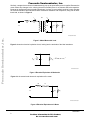
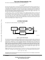
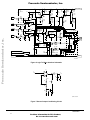
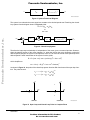
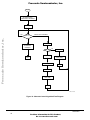
Order this document by: A N 1 2 4 9 / D
Freescale Semiconductor
Brushed DC Motor Control Using the MC68HC16Z1
by Lawrence Donahue
Freescale Semiconductor, Inc...
INTRODUCTION
The MC68HC16Z1 is a 16-bit high speed microcontroller that incorporates a number of different modules.
One of these modules is the General Purpose Timer (GPT), which provides various timing functions including pulse width modulation (PWM) output. PWM is very useful for motor control. This note describes a DC
motor control system that provides for constant motor speed using PWM.
The control system uses motor shaft rotation period as its input, monitors motor speed, and changes PWM
output duty cycle to either speed up or slow down the motor in order to maintain constant speed. The
M68HC16 interfaces to the motor via the DEVB103 Logic to Motor Interface Module, which is described in
detail in Freescale Application Note AN1300,Interfacing Microcomputers to Fractional Horsepower Motors.
BACKGROUND
A DC motor is a transducer that converts electrical energy to mechanical energy. As shown in Figure 1, an
ideal motor would run without loss and store no energy.
Is
K:1
Fm
Um
Vs
AN1249 IDEAL MOTOR
Figure 1 Ideal Motor
The model of an ideal motor is similar to that of an ideal transformer, but only one side has voltage (V) and
current (I) variables, while the other side has velocity (U) and force (F) variables. The voltage-velocity and
current-force relationships are:
KIs = Fm
Vs = KUm
However, a real motor is far from ideal, both electrically and mechanically. The electrical side consists essentially of wire wound around a core. The windings have an associated inductance, and since wire has
resistivity, there is also a finite resistance. Inertia affects mechanical operation. A rotating motor does not
instantaneously stop when disconnected from its power source, but rather slows down and eventually stops.
© Freescale Semiconductor, Inc., 2004. All rights reserved.
For More Information On This Product,
Go to: www.freescale.com
Freescale Semiconductor, Inc.
Similarly, a stopped motor does not instantaneously jump up to speed when power is applied. Because the
motor resists step changes in the velocity (the across variable) there is an element that looks capacitive.
Because an unpowered motor eventually slows down, it is lossy. A more realistic model of a motor includes
an electrical resistance and inductance and a mechanical resistance and compliance, along with an additional load, as shown in Figure 2.
K:1
Is
Re
Fm
Le
Um
Freescale Semiconductor, Inc...
Vs
Cm
Rm
RL
AN1249 NONIDEAL MOTOR
Figure 2 Model Motor with Load
Figure 3 shows the electrical equivalent circuit, looking into the terminals of the ideal transducer.
Cm
C eq = --------K2
R eq = K 2 R m R L ( R m + R L )
–1
AN1249 MECH ELEC EQIV
Figure 3 Electrical Equivalent of Mechanics
Figure 4 is the second-order electronic equivalent of the motor.
Re
Vs
Le
Ceq
Req
AN1249 MOTOR ELEC EQUIV
Figure 4 Electrical Equivalent of a Motor
2
AN1249/D
For More Information On This Product,
Go to: www.freescale.com
Freescale Semiconductor, Inc.
The result is a second order model system with a natural frequency of:
ω0 = [LeCeq]-1/2
The input to this model system is a pulse-width modulated signal that switches between ground and a constant voltage. Switching occurs at a constant frequency with a given duty cycle. If the switching frequency
is sufficiently above the bandwidth of the motor, the motor filters out everything but the DC component of
the PWM signal, thus averaging it. For example, consider a PWM that switches between 0 volts and V0 volts
with a duty cycle of 25%. The motor behaves as if it were connected to a DC supply of 0.25V0 volts — the
duty cycle of the PWM determines the speed of the motor.
Freescale Semiconductor, Inc...
In real DC motors, however, the relationship between source voltage and shaft velocity is not linear, and
these relationships vary from motor to motor. Therefore, one desirable characteristic of a motor control system is the ability to control speed independent of motor characteristics. Also, in many real-world applications, motor loads vary. Hence, another desirable characteristic is the ability to provide constant motor
speed under changing loads. These requirements are addressed by monitoring and controlling motor speed
rather than providing a specific voltage or duty cycle.
SYSTEM OVERVIEW
The system has four basic elements, as shown in Figure 5.
68HC16Z1EVB
LOGIC-TO-MOTOR
INTERFACE
MOTOR
OPTICAL
SENSOR
SENSOR BOARD
AN1249 SYS BLOCK
Figure 5 System Block Diagram
The first block represents the (MC68HC16Z1EVB) evaluation board that provides system computing and
control functions. The MCU is accessed by EVB16 software running on an IBM PC compatible connected
to the EVB via a parallel port. The GPT in the MCU generates a PWM signal which is connected to the
DEVB103 logic to motor interface module (Figure 6). The logic to motor interface module takes logic level
PWM signals and switches the power transistors of an H-bridge to provide motor drive power up to 60 V
and 3 A. The motor is the third element of the system. The fourth element consists of an opto-sensor and a
sensor board that conditions sensor output so that the period of motor shaft rotation can be measured by
software, to complete the feedback loop. Figure 7 shows a typical comparator with unipolar output. Comparator component values depend on sensor output level.
Figure 10 shows the open loop system function. The input is D, the duty cycle that determines the speed
of the motor. The output is ωA, the actual speed of the motor. Hence, the transfer function of the motor is:
ωA / D = [s2 + 2αs + ω02]-1
Observations of the actual motor indicate that the open loop system function is overdamped, and thus looks
somewhat like a first order system.
AN1249/D
For More Information On This Product,
Go to: www.freescale.com
3
Freescale Semiconductor, Inc.
+ C1
390 m F
A BOT
R12
R22
10K
D7
4.7V
R13
A TOP
R23
10K
B BOT
R24
10K
Freescale Semiconductor, Inc...
2
R25
10K
+5V
1K D8
4.7V
R14
1K
4
5
+5V
D10
4.7V
C5
1 mF
14
3
U1A
Q4
MPS
A06
R7
5.6K
R9
3.9K
R21
2K
C7
1 mF
Q2
MPS
A56
6
U1B
Q6
MPS
A06
R20
5.6K
B+ (12-60V)
R18
100
Q5
MPS
A06
R6
220
R10
220
MC74HC00
C6
1 mF
R8
100
Q3
MPS
A06
D6
12V
R19
220
R17
220
Q7
MPS
A56
MC74HC00
9
10
1K
D9
4.7V
R15
B TOP
+5V
1
1K
D5
12V
12
13
R26
5.1K
1W
8
U1C
MC74HC00
U1D
7
11
R3
5.1K
1W
D4
14V
MC74HC00
1
2
3
4
U2
MC34151
NC
A IN
GND
B IN
+5V
Q1
MPS
W06
Q6
MPS
W06
C2
1 mF
U3
MC78L05ACP
G VO
VI
N
D
8
NC
A OUT 7
6
VCC
5
B OUT
D2
D3
PWR
C4
1 mF
B TOP
A TOP
10
3
B BOT
9
R2 220
MBR030
R1 470
D11
MBR030
CURRENT SENSE GND (CS-)
R16
2K
11
2
1
R4 470
C3
1 mF
CURRENT SENSE (CS+)
MPM3002
12
D1
MBR030 R11 220
R27
120
D12
MBR030 R5 1K
GROUND
-M
A BOT
4
6
5
8
7
GROUND
LTM SCHEM
Figure 6 Logic To Motor Interface Schematic
+V
VIN
+
R4
V OUT
–
–V
Z1
V REF
R1
RB
R2
R3
Q1
D1
SCHMITT COND CKT
Figure 7 Sensor Output Conditioning Circuit
4
+M
AN1249/D
For More Information On This Product,
Go to: www.freescale.com
Freescale Semiconductor, Inc.
D
2 –1
2
( s + αs + ω o )
VREF
ωA
AN1249 SYS FUNC BLOCK
Figure 8 System Functional Diagram
The system is to maintain the motor speed ωA constant at the desired speed
loop system function diagram shown in Figure 9 yields:
ωD. Examining the closed-
D = D + [ωD - ωA]/ωD
or
Freescale Semiconductor, Inc...
ω A = ωD
ωD
Σ
ωD
–1
Σ
D
2 –1
2
( s + 2αs + ω o )
VREF
ωA
Figure 9 Closed Loop System
Therefore the input-output relationship is independent of the motor given a constant input ωD. However,
when the transfer function of the motor changes (i.e., when the load on the motor changes) or when the
desired speed changes, the system must adjust the value of D to make the actual motor speed equal the
desired speed. Further examination of the system function yields:
D = D + [ωD - ωA] / ωD = (ωA/Vref) (s2 + 2as + ω02)
which simplifies to:
ωA = Vref (1 + D) [s2 + 2αs +ω02 +Vref/ωD]-1
As shown in Figure 10, the poles of the closed loop system function differ from those of the open loop function. The poles become:
1/2
s1 = - α + [α2 - ω02 - Vref/ωD]
1/2
s2 = - α – [α2 - ω02 - Vref/ωD]
Im
Im
x
x
x
–α
Re
Re
–α
x
OPEN LOOP
CLOSED LOOP
AN1249 LOOP POLAR
Figure 10 Open Loop and Closed Loop Poles in Complex Plane
AN1249/D
For More Information On This Product,
Go to: www.freescale.com
5
Freescale Semiconductor, Inc.
The poles are thus functions of Vref/ωD. If Vref/ωD gets large enough, the poles become complex, and the
actual motor speed, ωA, rings as it settles to its final value of ωD. The envelope and overshoot of the ringing
are both dependent on several factors, including the control algorithm, the voltage and duty cycle used for
the PWM, the desired speed, the load on the motor, and the motor itself.
SOFTWARE CONTROL
The software that controls the motor brings the motor up to speed as fast as possible, given the voltage
constraints of the system, and then maintains that desired speed. Figure 12 is an overall block diagram of
the system software. Figure 13 through Figure 15 provide flow diagrams of the three major blocks of code.
Freescale Semiconductor, Inc...
Begin sets up the registers that control the GPT, sets the desired period of rotation and tolerances, and sets
the PWM to 100%. Startup then monitors the period of rotation of the motor by using the subroutine measure (refer to Figure 13). If measure returns a period longer than that desired, the program loops back to
startup. When measure returns a period shorter than that desired, the program continues with new_duty
(refer to Figure 13), which calculates and sets the new duty cycle with the algorithm:
Dnew = Dold [1 + (TD - TA)/TA]-1
where TD and TA are the desired and actual periods of rotation, respectively. Following new_duty, tolerance
(refer to Figure 14) checks to see if the measured period is within the tolerances designated in begin.
For experimental purposes, a second control algorithm that modifies the duty cycle in a different manner
was also implemented. The routine compares TD and TA and determines whether TA is greater or less than
TD, then takes one of the following actions:
• If the two periods are within 8 GPT counts, the duty cycle is not modified.
• If TD - 8 is greater than TA, the duty cycle is decreased.
• if TD + 8 is less than TA, the duty cycle is increased.
The routine then looks at the magnitude of the difference between the two periods to determine by how
much the duty cycle is to be modified. Figure 16 is a flow diagram of the alternate control algorithm.
Figure 11 is a plot of the increment by which the duty cycle is modified as a function of the difference between TD and TA.
MODIFY
VALUE
8
6
4
2
#$8 #$10
#$40
TD – TA
#$100
GPT COUNTS
AN1249 MOD VS DIFF
Figure 11 Modify Value vs. Difference
6
AN1249/D
For More Information On This Product,
Go to: www.freescale.com
Freescale Semiconductor, Inc.
START
BEGIN
SETS GPTMCR, TCTL2, ICR, CSOR0,
AND CSBAR0 TO PROVIDE FOR THE IC1
INTERRUPT. INITIALIZES PWM TO 100% DUTY
CYCLE.
Freescale Semiconductor, Inc...
STARTUP
CALLS 'MEASURE' AND LOOPS IF THE
RESULTING PERIOD OF ROTATION IS GREATER
THAN THE DESIRED PERIOD.
NEW_DUTY
CALCULATES AND STORES THE NEW DUTY CYCLE
IN THE DUTY MEMORY LOCATION.
TOLERANCE
CHECKS TO SEE IF THE ACTUAL PERIOD OF
ROTATION IS WITHIN THE TOLERANCES AND JUMPS
TO 'NEW_DUTY' IF IT'S NOT. OTHERWISE,
LOOPS.
AN1249 SOFTWARE FLOW
Figure 12 System Software Flow Diagram
AN1249/D
For More Information On This Product,
Go to: www.freescale.com
7
Freescale Semiconductor, Inc.
START
CALL “MEASURE“
IS “DESIRED“ - “ACTUAL“
POSITIVE?
NO
YES
Freescale Semiconductor, Inc...
BRANCH TO “NEW_DUTY“
Figure 13 Startup Routine Flow Diagram
START
“DESIRED” + “DELTA” – “ACTUAL”
IS RESULT NEGATIVE?
YES
NO
BRANCH TO “NEW_DUTY”
“DESIRED” – “DELTA” – “ACTUAL”
IS RESULT POSITIVE?
YES
NO
BRANCH TO “NEW_DUTY”
AN1249 MEAS FLOW
Figure 14 Tolerance Subroutine Flow Diagram
8
AN1249/D
For More Information On This Product,
Go to: www.freescale.com
Freescale Semiconductor, Inc.
START
DESIRED – ACTUAL
GREATER THAN
ZERO?
NO
YES
NEGATE RESULT
Freescale Semiconductor, Inc...
DIVIDE BY ACTUAL
DIVIDE BY ACTUAL
SHIFT ONE SPACE
TO THE RIGHT
ADD RESULT TO
1 ($8000)
SHIFT ONE SPACE
TO THE RIGHT
SUBTRACT RESULT
FROM 1 ($8000)
MULTIPLY RESULT
BY DUTY
SHIFT ONE SPACE
TO THE RIGHT
LOAD RESULT IN
DUTY
JUMP TO
"TOLERANCE"
.
AN1249 DUTY FLOW
Figure 15 New_duty Routine Flow Diagram
AN1249/D
For More Information On This Product,
Go to: www.freescale.com
9
Freescale Semiconductor, Inc.
START
SET TMSK1 TO 0100
TO MASK FOR IC1 INTERRUPT
SET A TO 0
Freescale Semiconductor, Inc...
YES
“PERIOD” ON IC1 INTERRUPT
IS A < 2?
NO
TMSK1 = 0000
TO DISABLE IC1
INTERRUPT
INCREMENT A.
A = 2?
NO
YES
RTS
TIC1 => D
ACTUAL = –(E – D)
TIC1 => E
TFLG1 = F880
RTI
SET A TO 2.
TFLG = F880
RTI
AN1249 ALT FLOW
Figure 16 Alternate Control Algorithm Flow Diagram
10
AN1249/D
For More Information On This Product,
Go to: www.freescale.com
Freescale Semiconductor, Inc.
OPERATION
Both control routines were evaluated on two different motors. One motor was a slower, less responsive motor that worked well with the second increment/decrement approach and not so well with the first approach.
The second motor was faster and more responsive and worked very well with the first approach but not so
well with the second approach.
CODE LISTINGS
Listings 1 and 2 contain code for the first implementation of the control routine and the second increment/
decrement implementation of the control routine, respectively.
Freescale Semiconductor, Inc...
Listing 1 First Control Implementation.
DESIRED
DELTA
ACTUAL
DUTY
TEMP1
TEMP2
TEMP3
TEMP4
*****
*****
INCLUDE 'EQUATES.ASM'
INCLUDE 'ORG00000.ASM'
;table of EQUates for common register addr
;initialize reset vector
ORG
DC.W
$80
PERIOD
;IC1 jumps to PERIOD
ORG
EQU
EQU
EQU
EQU
EQU
EQU
EQU
EQU
$0400
$0
$2
$4
$6
$8
$A
$C
$E
;offsets from
;location for
;location for
;location for
;location for
;location for
;
"
"
;
"
"
;
"
"
IX for variables
storing the desired period
storing the period tolerance
storing the measured period
storing the present duty cycle
storing any temporary values
"
"
"
"
"
"
"
"
"
"
"
"
ORG
$0200
;start program after interrupt vectors
Initialization Routines *****
INCLUDE 'INITRAM.ASM'
;initialize and turn on SRAM
;set stack (SK=1, SP=03FE)
INCLUDE 'INITSYS.ASM'
;initially set EK=F, XK=0, YK=0, ZK=0
;set sys clock at 16.78 MHz, disable COP
Here we go with motor control.
BEGIN
STARTUP
LDD
STD
LDD
STD
LDD
STD
LDD
STD
#$0083
GPTMCR
#$FFF9
CSBAR0
#$7801
CSOR0
#$1740
ICR
LDY
LDD
STD
LDD
STD
LDAA
STAA
LDD
STD
BSR
CPE
BPL
LDD
STD
STAB
#$400
#$A00
DESIRED,Y
#$80
DELTA,Y
#$01
TCTL2
#$0062
PWMC
MEASURE
DESIRED,Y
STARTUP
#$00FF
DUTY,Y
PWMA
LDD
STD
MEAS_LOOP
JMP
LDD
STD
LDAA
CMPA
TOLERANCE
BMI
LDD
STD
RTS
BSR
MEASURE
*****
;Put the GPT into supervisor mode (the default
;mode) and sets interrrupt priority level to 3.
;assert AVEC and other int. vector stuff
;Set IC1 to be highest GPT priority, GPT to...
;highest priority interrupt, and vector base...
;address to 4.
;Beginning for variables in indirect addresses.
;Set the desired period to $A00 GPT counts.
;Set the tolerence to +/- $80 GPT counts.
;Set IC1 to capture only on a positive edge.
;Set the input of PWMCNT to the system clock...
;divided by 128 and set PWMA to be allways high.
;Branch to measure period of revolution
;Compare the measured period with the desired
;and loop if motor is slower than desired.
;Store the value $FF in...
;...the user defined duty cycle location and...
;...in the GPT PWMA register thus setting the...
;...duty cycle of PWMA to $FF/$100.
#$0060
;Change PWMA's otput to be from a constant...
PWMC
;...output to a PWM output with duty cycle...
;...in the PWMA register.
NEW_DUTY ;branch to get new duty cycle
#$0104
;Enable the IC1 interrupt and the TCNT clock...
TMSK1
;...to be the OC1 pin.
#$00
;The A register is used to keep track of how...
#$02
;...many input captures have taken place--with...
;...two, we can measure the period.
MEAS_LOOP ;Loop if two measurements have not been made.
#$0000
;If two interrupts have taken place,reset for...
TMSK1
;...no interrupts (disable IC1).
;Return from "measure" subroutine.
MEASURE
;Branch to "measure" subroutine.
AN1249/D
For More Information On This Product,
Go to: www.freescale.com
11
Freescale Semiconductor, Inc.
LDE
LDD
ASLD
SDE
BPL
LDD
LDE
ASLE
SDE
BMI
TOO_SLOW
TOO_FAST
Freescale Semiconductor, Inc...
WITHIN
BRA
LDD
STD
STAB
BRA
LDD
STD
STAB
BRA
LDD
LDE
ADE
LDD
SDE
BMI
LDD
LDE
NEGE
ADE
JUMP
WAIT
LDD
SDE
BPL
JMP
LDE
LDD
STD
WAIT_LOOP
INCW
CPE
BNE
BRA
PERIOD
INCA
DELTA_T
CMPA
BEQ
LDE
BCLR
RTI
LDD
SDE
NEGE
STE
NEW_DUTY
LDAA
BCLR
RTI
LDD
LDE
SDE
BPL
MINUS
NEGE
TED
LDX
FDIV
STX
LDD
LSRD
LDE
SDE
BRA
12
ACTUAL,Y ;Load the measured period in E
DESIRED,Y ;Load the desired period in D.
;Double the desired period and put in D.
;Subtract twice the desired period from the...
;...actual period, and if the actual period is...
TOO_SLOW ;...more than twice the desired, branch to the...
;...the "too_slow" code.
DESIRED,Y ;Load the desired period in D.
ACTUAL,Y ;Load the measured period in E.
;Half the desired period and put in D.
;Subtract half the desired period from the...
;...actual period, and if the actual period is...
TOO_FAST ;...less than half the desired, branch to the...
;...the "too_fast" code.
WITHIN
;Otherwise branch to the "within" code.
#$00FF
DUTY,Y
;Set the user defined duty cycle location to $FF.
PWMA
;Set the PWMA register for a $FF/$100 duty cycle.
WAIT
;Branch to the "wait" code.
#$0000
DUTY,Y
;Set the user defined duty cycle location to 0.
PWMA
;Set the PWMA register for a 0% duty cycle.
WAIT
;Branch to the "wait" code.
DESIRED,Y ;Load the desired period in D.
DELTA,Y
;Load the period tolerance in E.
;Add the two together to get the maximum...
;...period allowed and store in E.
ACTUAL,Y ;Load the measured period in D and...
;...subtract it from the max period allowed.
JUMP
;Branch to get new duty cycle if slow.
DESIRED,Y ;Load the desired period in D.
DELTA,Y
;Load the period tolerance in E.
;Negate the period tolerance.
;Add the two together to get the minimum...
;... period allowed and store in E.
ACTUAL,Y ;Load the measured period in D and...
;...subtract it from the min period allowed.
JUMP
;Branch to get new duty cycle if fast.
NEW_DUTY ;Jump to "new_duty" code.
#$2
;Load the number of loops to wait for in E.
#$0000
;Initialize temporary loacation #1 with zero...
TEMP1,Y
;...because it will be used to count the number...
;...of loops.
TEMP1,Y
;Increment the counter loop.
TEMP1,Y
;Has the count (TEMP1,Y) reached the value in E?
WAIT_LOOP ;Loop if the count hasn't reached the value in E.
TOLERANCE ;Branch back to tolerance once the count has...
;...reached the specified value.
;This code is executed when the IC1 interrupt...
;...takes place. The code first increments A...
;...which is used to count how many edges have...
;...been detected in the present "measure" routine.
#$02
;Compare the number of edge detections to 2.
DELTA_T
;If second edge, jump to DELTA_T routine.
TIC1
;Load the TCNT input capture value in E.
TFLG1,#$01 ;Clear the IC1 interrupt flag.
;Return from the IC1 interrupt.
TIC1
;Load the TCNT input capture value in D.
;Subtract the second time (D) from first (E)...
;...and change the sign to get possitive value...
;...for the period.
ACTUAL,Y ;Store the period in the appropriate location...
;...of user specified memory (ACTUAL,Y).
#$02
;Set A to 2 to break out of MEAS_LOOP above.
TFLG1,#$01 ;Clear the IC1 interrupt flag.
;Return from the IC1 interrupt.
ACTUAL,Y ;Load the measured period into D.
DESIRED,Y ;Load the desired period into E.
;Subtract the desired period from the measured...
;...and put result in E.
PLUS
;Branch to the "plus" code if the desired period...
;...is greater than the measured period.
;-(Desired-Measured) ==> E
;-(Desired-Measured) ==> E
ACTUAL,Y ;Load the measured period into the IX register.
;(Actual-Desired)/Actual ==> IX
TEMP1,Y
;Store the result in user defined memory...
TEMP1,Y
;...TEMP1,Y and store the result in D.
;Shift bits one place to the right because in...
#$8000
;...this section, the convention changes and...
;...$8000 becomes equal to 1 instead of 0.5.
;Subtract the word shifted above from $8000 thus...
;...performing: 1-(Actual-Desired)/Actual ==> E.
FACTOR
;Branch to section of code that will scale the...
;...present duty cycle by the result stored in E.
AN1249/D
For More Information On This Product,
Go to: www.freescale.com
Freescale Semiconductor, Inc.
PLUS
LDX
TED
FDIV
STX
LDD
LSRD
LDE
;Load the measured period into the IX register.
;(Desired-Actual) ==> E
;(Desired-Actual)/Actual ==> IX
TEMP1,Y
;Store the result in user defined memory...
TEMP1,Y
;...TEMP1,Y then load the result in D.
;Shift bits one place to the right because in...
#$8000
;...this section, the convention changes and...
;...$8000 becomes equal to 1 instead of 0.5.
;Add the word shifted above to $8000 thus...
;...performing: 1+(Desired-Actual)/Actual ==> E.
TEMP1,Y
;Store the result from "minus" or "plus" in...
TEMP1,Y
;...user defined memory TEMP1,Y then load the...
;...result in IX.
DUTY,Y
;Load D with the present duty cycle.
;Divide the presest duty cycle by the factor...
;...calculated in "minus" or "plus" above...
;...thus performing the operation:...
;...DUTY/(1+(Desired-Actual)/Actual) ==> IX.
TEMP1,Y
;Store this result in user defined memory...
TEMP1,Y
;...and then loading the result in D.
;Shift the result one place to the right to..
;...compensate for the shift from above.
DUTY,Y
;Load this result in the memory location...
;...designated to be the duty cycle--DUTY,Y.
#$00FF
;Load E with $FF and compare with the result...
;...as a sanity check to make sure that the..
;...resulting duty cycle makes sense.
OK
;If the result passes the sanity check, branch...
;...to OK code,...
#$00FF
;...otherwise, load the maximum allowable duty...
DUTY,Y
;...cycle ($FF/$100) into DUTY,Y.
PWMA
;Store the new duty cycle in the GPT PWMA register.
TOLERANCE ;Loop back to TOLERANCE.
ADE
ACTUAL,Y
FACTOR
STE
LDX
LDD
FDIV
STX
LDD
LSRD
Freescale Semiconductor, Inc...
STD
LDE
SDE
BPL
LDD
STD
STAB
JMP
OK
Listing 2 Second (Increment/Decrement) Control Implementation
DESIRED
DELTA
ACTUAL
DUTY
TEMP1
TEMP2
TEMP3
TEMP4
*****
*****
INCLUDE 'EQUATES.ASM'
INCLUDE 'ORG00000.ASM'
;table of EQUates for common register addr
;initialize reset vector
ORG
DC.W
$80
PERIOD
;IC1 jumps to PERIOD
ORG
EQU
EQU
EQU
EQU
EQU
EQU
EQU
EQU
$0400
$0
$2
$4
$6
$8
$A
$C
$E
;Offsets from
;Location for
;Location for
;Location for
;Location for
;Location for
;Location for
;Location for
;Location for
IX for variables
storing the desired period.
storing the period tolerance.
storing the measured period.
storing the present duty cycle.
storing any temporary values.
storing any temporary values.
storing any temporary values.
storing any temporary values.
ORG
$0200
;start program after interrupt vectors
Initialization Routines *****
INCLUDE 'INITRAM.ASM'
;initialize and turn on SRAM
;set stack (SK=1, SP=03FE)
INCLUDE 'INITSYS.ASM'
;initially set EK=F, XK=0, YK=0, ZK=0
;set sys clock at 16.78 MHz, disable COP
Here we go with motor control.
BEGIN
STARTUP
LDD
STD
LDD
STD
LDD
STD
LDD
STD
LDY
LDD
STD
LDD
STD
LDAA
STAA
LDD
STD
BSR
CPE
BPL
LDD
#$0083
GPTMCR
#$FFF9
CSBAR0
#$7801
CSOR0
#$1740
ICR
*****
;Put the GPT into supervisor mode (the default...
;...mode) and sets interrupt priority level to 3.
;assert AVEC and other int. vector stuff
;Set IC1 to be highest GPT priority, GPT to...
;...highest priority interrupt, and vector base...
;...base address to 4.
;Beginning for variable in indirect addresses.
;Set the desired period to $A00 GPT counts.
#$400
#$A00
DESIRED,Y
#$8
;Set the period tolerance to +/- $8 GPT counts.
DELTA,Y
#$01
;Set IC1 to capture only on a positive edge.
TCTL2
#$0062
;Set the input of PWMCNT to the system clock...
PWMC
;...divided by 128 and set PWMA to be high always.
MEASURE
;Branch to measure period of revolution.
DESIRED,Y ;Cpmpare the measured period with the desired...
STARTUP
;...and loop if motor is slower than desired
#$00FF
;Store the value $FF in...
AN1249/D
For More Information On This Product,
Go to: www.freescale.com
13
Freescale Semiconductor, Inc.
STD
STAB
LDD
STD
MEASURE
MEAS_LOOP
Freescale Semiconductor, Inc...
TOLERANCE
JMP
LDD
STD
LDAA
CMPA
BMI
LDD
STD
RTS
BSR
LDD
LDE
ADE
LDD
SDE
BMI
LDD
LDE
NEGE
ADE
JUMP
LDD
SDE
BPL
JMP
WAIT
LDE
LDD
STD
WAIT_LOOP
INCW
CPE
BNE
BRA
PERIOD
INCA
DELTA_T
CMPA
BEQ
LDE
BCLR
RTI
LDD
SDE
NEGE
STE
NEW_DUTY
LDAA
BCLR
RTI
LDD
LDE
SDE
BPL
MINUS
NEGE
STE
LDD
SDE
BPL
LDD
TWO_PL
JMP
LDE
LDD
SDE
BPL
LDD
14
DUTY,Y
PWMA
;...the user defined duty cycle location and...
;...in the GPT PWMA register thus setting the...
;...duty cycle of PWMA to $FF/$100.
#$0060
;Change PWMA's output to be from a constant...
PWMC
;...ooutput to a PWM output with duty cycle...
;...in the PWMA register.
NEW_DUTY ;Branch to get new duty cycle.
#$0104
;Enable the IC1 interrupt and the TCNT clock...
TMSK1
;...to be the OC1 pin (as a reference for debug).
#$00
;The A register os used to keep track of how...
#$02
;...many input captures have taken place--with...
;...two, we can measure the period.
MEAS_LOOP ;Loop if two measurements have not been made.
#$0000
;If two interrupts have taken place, reset for...
TMSK1
;...no interrupts (disable IC1).
;Return from "measure" subroutine.
MEASURE
;Branch to "measure" subroutine.
DESIRED,Y ;Load the desired period into D.
DELTA,Y
;Load the period tolerance into E.
;Add the two together to get the maximum...
;...period allowed and store the value in E.
ACTUAL,Y ;Load the measured period in D and...
;...subtract it from the max period allowed.
JUMP
;Branch to get new duty cycle if slow.
DESIRED,Y ;Load the desired period into D.
DELTA,Y
;Load the period tolerance into E.
;Negate the period tolerance.
;Add the two together to get the minimum...
;...period allowed and store it in E.
ACTUAL,Y ;;Load the measured period in D and...
;...subtract it from the min period allowed.
JUMP
;Branch to get new duty cycle if fast.
NEW_DUTY ;Jump to "new_duty" code which calculates the...
;...new duty cycle.
#$2
;Load the number of loops to wait for in E.
#$0000
;Initialize temporary location #1 with zero...
TEMP1,Y
;...because it will be used to keep track of...
;...the number of loops.
TEMP1,Y
;Increment the loop counter.
TEMP1,Y
;Has the count (TEMP1,Y) reached the value in E?
WAIT_LOOP ;Loop if the count hasn't reached the value in E?
TOLERANCE ;Branch back to tolerance once the count has...
;...reached the specified value.
;This count is executed when the IC1 interrupt...
;takes place. The code first increments A which...
;...is used to count how many edges have been...
;...detected in the present "measure" routine.
#$02
;Compare the number of edge detections to 2.
DELTA_T
;If second edge, jump to DELTA_T routine.
TIC1
;Load the TCNT input capture value in E.
TFLG1,#$01 ;Clear the IC1 interrupt flag
;Return from the IC1 interrupt.
TIC1
;Load the TCNT input capyure value in D.
;Subtract the second time (D) from first (E)...
;...and change the sign to get positive value...
;...for the period.
ACTUAL,Y ;Store the measured period in the appropriate...
;location of user specified memory (ACTUAL,Y).
#$02
;Set A to 2 to break out of MEAS_LOOP above.
TFLG1,#$01 ;Clear the IC1 interrupt flag.
;Return from the IC1 interrupt.
ACTUAL,Y ;Load the measured period into D.
DESIRED,Y ;Load the desired period into E.
;Subtract the desired period from the measured...
;...and put the result in E.
PLUS
;Branch to the "plus" code if the desired...
;...period is greater than the measured period.
;Load -(Desired-Measured) into register E.
TEMP1,Y
;Store -(Desired-Measured) into location TEMP1,Y.
#$0010
;Load the value $10 into register D.
;Subtract $10 from the discrepency between the...
;...measured period and the desired period.
TWO_PL
;If the discrepency is greater than $10, branch...
;...to the "two_pl" code.
#$0001
;If the discrepency is less than $10, load 1...
;...into D to be the value to add to the present...
;...duty cycle.
OK_PL
;Jump to the "ok_pl" code.
TEMP1,Y
;Load -(Desired-Measured) from TEMP1,Y into E.
#$0040
;Load the value $40 into register D.
;Subtract $40 from the discrepency between the...
;...measured period and the desired period.
FOUR_PL
;If the discrepency is greater than $40, branch...
;...to the "four_pl" code.
#$0002
;If the discrepency is less than $40, load 2...
AN1249/D
For More Information On This Product,
Go to: www.freescale.com
Freescale Semiconductor, Inc.
FOUR_PL
JMP
LDE
LDD
SDE
BPL
LDD
EIGHT_PL
JMP
LDD
OK_PL
LDE
ADE
STE
LDD
LDE
SDE
Freescale Semiconductor, Inc...
BPL
PLUS
LDD
STD
BRA
STE
LDD
SDE
BPL
LDD
TWO_MI
JMP
LDE
LDD
SDE
BPL
LDD
FOUR_MI
JMP
LDE
LDD
SDE
BPL
LDD
EIGHT_MI
JMP
LDD
OK_MI
LDE
SDE
STE
LDD
LDE
SDE
BMI
OK
LDD
STD
STAB
JMP
;...into D to be the value to add to the present...
;...duty cycle.
OK_PL
;Jump to the "ok_pl" code.
TEMP1,Y
;Load -(Desired-Measured) from TEMP1,Y into E.
#$0100
;Load the value $100 into register D.
;Subtract $100 from the discrepency between the...
;...measured period and the desired period.
EIGHT_PL ;If the discrepency is greater than $100,...
;...branch to the "eight_pl" code.
#$0004
;If the discrepency is less than $100, load 4...
;...into D to be the value to add to the present...
;...duty cycle.
OK_PL
;Jump to the "ok_pl" code.
#$0008
;Load 8 into D to be the value to add to the...
;...present duty cycle.
DUTY,Y
;Load the present duty cycle into register E...
;...and add it to the value obtained above...
;...to get the new duty cycle and put result in E.
DUTY,Y
;Store the new duty cycle in DUTY,Y.
DUTY,Y
;Load the new duty cycle from DUTY,Y into D.
#$00FF
;Load E with $FF and compare with the result...
;...as a sanity check to make sure that the...
;...resulting duty cycle makes sense.
OK
;If the result passes the sanity check, branch...
;...to "ok" code...
#$00FF
;...otherwise, load the maximum allowable duty...
DUTY,Y
;...cycle ($FF/$100) into DUTY,Y.
OK
;Branch to "ok" code.
TEMP1,Y
;Store (Desired-Measured) into location TEMP1,Y.
#$0010
;Load the value $10 into register D.
;Subtract $10 from the discrepency between the...
;...measured period and the desired period.
TWO_MI
;If the discrepency is greater than $10,...
;...branch to the "two_mi" code.
#$0001
;If the discrepency is less than $10, load 4...
;...into D to be the value to add to the...
;...present duty cycle.
OK_MI
;Jump to the "ok_mi" code.
TEMP1,Y
;Load (Desired-Measured) from TEMP1,Y into E.
#$0040
;Load the value $40 into register D.
;Subtract $40 from the discrepency between the...
;...measured period and the desired period.
FOUR_MI
;If the discrepency is greater than $40,...
;...branch to the "four_mi" code.
#$0002
;If the discrepency is less than $40, load 2...
;...into D to be the value to add to the...
;...present duty cycle.
OK_MI
;Jump to the "ok_mi" code.
TEMP1,Y
;Load (Desired-Measured) from TEMP1,Y into E.
#$0100
;Load the value $100 into register D.
;Subtract $100 from the discrepency between the...
;...measured period and the desired period.
EIGHT_MI ;If the discrepency is greater than $100,...
;...branch to the "eight_mi" code.
#$0004
;If the discrepency is less than $100, load 4...
;...into D to be the value to add to the...
;...present duty cycle.
OK_MI
;Jump to the "ok_mi" code.
#$0008
;Load 8 into D to be the value to add to the...
;...present duty cycle.
DUTY,Y
;Load the present duty cycle into register E...
;...and subtract from it the value obtained above...
;...to get the new duty cycle and put result in E.
DUTY,Y
;Store the new duty cycle in DUTY,Y.
DUTY,Y
;Load the new duty cycle from DUTY,Y into D.
0
;Load E with 0 and compare with the result...
;...as a sanity check to make sure that the...
;...resulting duty cycle makes sense.
OK
;If the result passes the sanity check, branch...
;...to "ok" code...
#$0
;...otherwise, load the minimum allowable duty...
DUTY,Y
;...cycle (0) into DUTY,Y.
PWMA
;Store the new duty cycle in the GPT PWMA register.
TOLERANCE ;Loop back to "tolerance" code.
AN1249/D
For More Information On This Product,
Go to: www.freescale.com
15
Freescale Semiconductor, Inc.
ADDITIONAL INFORMATION
The following Freescale publications contain additional information that may be of use to the reader.
The motor control system described in this note is based on an M68HC11-based system discussed in
Application Note AN1311,Software for an 8-bit Microcontroller Based Brushed DC Motor Drive. However, the M68HC11system uses a PWM signal as its input.
The DEVB103 Logic to Motor Interface Module is completely described in Application Note AN1300,
Interfacing Microcomputers to Fractional Horsepower Motors.
TheMC68HC16Z1 User’s Manual (MC68HC16Z1UM/AD) contains comprehensive information concerning the MC68HC16Z1 microcontroller.
TheGPT Reference Manual (GPTRM/AD) contains detailed information concerning the General-Purpose Timer (GPT) module in the MC68HC16Z1.
Freescale Semiconductor, Inc...
These publications are available through Freescale sales offices and Literature Distribution Centers.
How to Reach Us:
Home Page:
www.freescale.com
E-mail:
[email protected]
USA/Europe or Locations Not Listed:
Freescale Semiconductor
Technical Information Center, CH370
1300 N. Alma School Road
Chandler, Arizona 85224
+1-800-521-6274 or +1-480-768-2130
[email protected]
Europe, Middle East, and Africa:
Freescale Halbleiter Deutschland GmbH
Technical Information Center
Schatzbogen 7
81829 Muenchen, Germany
+44 1296 380 456 (English)
+46 8 52200080 (English)
+49 89 92103 559 (German)
+33 1 69 35 48 48 (French)
[email protected]
Japan:
Freescale Semiconductor Japan Ltd.
Headquarters
ARCO Tower 15F
1-8-1, Shimo-Meguro, Meguro-ku,
Tokyo 153-0064
Japan
0120 191014 or +81 3 5437 9125
[email protected]
Asia/Pacific:
Freescale Semiconductor Hong Kong Ltd.
Technical Information Center
2 Dai King Street
Tai Po Industrial Estate
Tai Po, N.T., Hong Kong
+800 2666 8080
[email protected]
Information in this document is provided solely to enable system and software
implementers to use Freescale Semiconductor products. There are no express or
implied copyright licenses granted hereunder to design or fabricate any integrated
circuits or integrated circuits based on the information in this document.
Freescale Semiconductor reserves the right to make changes without further notice to
any products herein. Freescale Semiconductor makes no warranty, representation or
guarantee regarding the suitability of its products for any particular purpose, nor does
Freescale Semiconductor assume any liability arising out of the application or use of
any product or circuit, and specifically disclaims any and all liability, including without
limitation consequential or incidental damages. “Typical” parameters which may be
provided in Freescale Semiconductor data sheets and/or specifications can and do
vary in different applications and actual performance may vary over time. All operating
parameters, including “Typicals” must be validated for each customer application by
customer’s technical experts. Freescale Semiconductor does not convey any license
under its patent rights nor the rights of others. Freescale Semiconductor products are
not designed, intended, or authorized for use as components in systems intended for
surgical implant into the body, or other applications intended to support or sustain life,
or for any other application in which the failure of the Freescale Semiconductor product
could create a situation where personal injury or death may occur. Should Buyer
purchase or use Freescale Semiconductor products for any such unintended or
unauthorized application, Buyer shall indemnify and hold Freescale Semiconductor
and its officers, employees, subsidiaries, affiliates, and distributors harmless against all
claims, costs, damages, and expenses, and reasonable attorney fees arising out of,
directly or indirectly, any claim of personal injury or death associated with such
unintended or unauthorized use, even if such claim alleges that Freescale
Semiconductor was negligent regarding the design or manufacture of the part.
For Literature Requests Only:
Freescale Semiconductor Literature Distribution Center
P.O. Box 5405
Denver, Colorado 80217
1-800-441-2447 or 303-675-2140
Fax: 303-675-2150
[email protected]
For More Information On This Product,
Go to: www.freescale.com