1
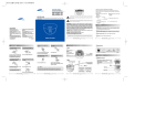
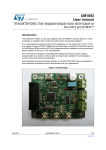
1.4
Adjustment of Motor Phase Current
Current Control
Voltage Control
Power
Error
Power
Error
1
Current Curve
2
3
Resolution
4
5 50kHz Filter ON/OFF
I 1
I 2
O 3
O 4
O 5
O 6
O 7
I 8
I 9
I 10
I 11
I 12
I 13
O 14
Operating Current
120 Ohm
Standby Current
1.4.2
GND /
Supply
Motor A +
Motor A Motor B +
Motor B Power Dump
Direction PNP
Stepclock PNP
Digital GND
Standby Current
Move Current
Current GND
Error
1
Current Curve
2
3
Resolution
4
5 50kHz Filter ON/OFF
+
I 1
I 2
O 3
O 4
O 5
O 6
O 7
I 8
I 9
I 10
I 11
I 12
I 13
O 14
+
Standby Current
GND /
Supply
Motor A +
Motor A Motor B +
Motor B Power Dump
Direction PNP
Stepclock PNP
Digital GND
Standby Current
Move Current
Current GND
Error
Operating
Current
TT0012GB
Motor Current Controlled by Voltage or Current
In cases where current control is not desired via an external resistor, but via an externally
applied voltage, terminals 11-13 can also be used.
A voltage in the range 0 to 2.50VDC should be applied to the two terminals, corresponding to motor currents of 0 to 3Amp for SMD41Ax, 0 to 6 Amp for SMD41/42Bx,
and 0 to 9 Amp for SMD41/42Cx.
If current control of the motor phase current using a standard signal in the range 0-20mA
is required, a 127 Ohm/1%(E48) or 120 Ohm/5%(E24) resistor should be connected
between "Current GND" and each input — see above illustration.
The relationship between the voltage at the terminals and the motor current is liniar
from 0 to full-scale.
10
JVL Industri Elektronik A/S — User Manual Step Motor Driver SMD41/42