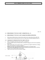
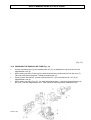
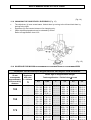
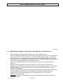
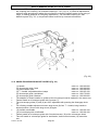
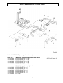
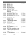
1
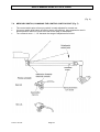
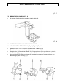
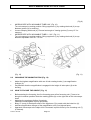
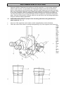
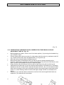
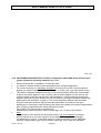
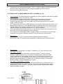
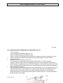
User´s Manual SOM 22 COLD LIGHT SOM 22 COLD LIGHT Stereo - Operation - and Diagnosis - Microscope ______________________________________________________________________ _______________________________________________________________________ Karl Kaps GmbH & Co.KG 06441 / 80704-0 Fax 06441 / 85985 Postfach 1225, D-35608 Asslar Europastraße, D-35614 Asslar www.kaps-optik.de e-mail: [email protected] This microscope is manufactured according to the EU direction 93 / 42 / EWG Products of medicine (MPG) 2005-05 Index: 01 REF 600.0150.B Page 1 User´s Manual SOM 22 COLD LIGHT LIST OF CONTENTS 1.0 Security indications, intended use 1.1 Security indications during the application 1.2 Warning for eye surgery 2.0 Condition of material at time of supply 3.0 Mounting of wall bracket (Fig.1) 4.0 Mounting of appliance (Fig. 2) 4.1 Special indication 4.2 Additional load 4.3 Measures, weight (Fig. 3) 5.0 Close electrical connections (Fig. 4) 5.1 Adjustment of mains voltage 5.2 Electrical connections 5.3 Changing of fuse (after removal of the defect) 6.0 Control elements (Fig. 5) 7.0 Operating instructions (Fig. 6) (Fig. 7) (Fig. 8) 7.1 On - / off switch (Fig. 6) 7.2 Change - over switch lamp I / lamp II (Fig. 6) 7.3 Brakes 7.4 Mercury – switch, changing the control switch – point (Fig.7) 7.5 Brightness control (Fig. 8) 8.0 Instructions for using the microscope 8.1 Adjusting the eye distance (Fig. 9) (Fig. 10) (Fig. 11) 8.2 Changing the magnification (Fig. 12) 8.3 How to focuse the object (Fig. 11) 8.4 Eyepieces with reticle (help for fine focussing and when using television or photo systems) (Fig. 12) 9.0 Breakdown of the cold light illumination (Fig. 13) 9.1 Breakdown of the cold light illumination during operation 9.2 Changing the xenon reflector lamp later on 10.0 Changing the binocular tube (Fig. 14) 11.0 Changing the objectives / eyepieces (Fig. 15) 12.0 Schedule for microscope magnification and object field measures 13.0 Objective quick changer (Fig. 16) 14.0 Compensation of weight when using accessories (Fig. 17) 15.0 Mounting of beam splitter (Fig. 17) 16.0 Observation tube monocular, observation tube binocular and assistance tube 90° (Fig. 18) 17.0 Photo tube with 35 mm camera, TV - tube with video camera (CCD) (Fig. 19) 18.0 Photographing without flash 19.0 How to get a sharp image on the TV screen (Fig. 20) 20.0 Mounting and operation of couplings (Fig. 21) 20.1 Mounting inclinable coupling 45° with balance system (Fig. 22) 21.0 Handles and microscope guides (Fig. 23) 22.0 Accessories (survey with order no.) 23.0 Desinfection and sterilization (Fig. 24) 24.0 Cleaning and service 25.0 Technical data 25.1 Declaration of conformity with EU rules KAPS 01.05.2005 Page 2 3 3 3 3 4 5 6 6 6 7 7 7 7 8 9 - 11 9 9 9 10 11 11 - 13 11, 12 12, 13 12 13 14 14 14 15 15 16 17 18 18 19 20 21 21, 22 23 24 25 26, 27 28 28 29 29 User´s Manual SOM 22 COLD LIGHT 1.0 SECURITY INDICATIONS, INTENDED USE This microscope is manufactured according to the security indications of electrical equipment and complies with the indicated IEC Puplications (IEC 601 - 1 / N 60601 -1 / VDE 0750 part 1). This instrument left KAPS Company in perfect condition. To guarantee the normal and safety use of the microscope it is necessary to read this user's manual attentively. This microscope is allowed to use in that way only as described in this manual. For service and repair only authorized persons are allowed to operate. Spare parts and accessories must be admitted by the manufacturer. If there are any questions, please contact our representatives. Please substitute burned out fuses by fuses of the same type only (rated voltage, rated current, switch - off characteristics). The microscope belongs to safety class I, use mains plug and mains socket both with protective earth conductors only. Be sure that inlets and outlets of ventilation system for cooling the housing are open (not covered). The microscope is built for use in dry rooms only. Take care that no fluids can enter the microscope components. Microscope is protected against overheating. A defect cooling system (fan is defect, inlets or outlets of cooling system are unintentionally covered) will be indicated by blinking of a red light emitting diode (3), Fig. 6, page 9. The protecting system reduces brightness of illumination automatically in that way that a surgeon can finish this activities and microscope will not be damaged. After the user's activities are being finished, cases of disturbances must be eliminated immediately, if this is not possible please advice service department. Very important: For identification, service people must know the serial number of the microscope! Please read it from the type label (4), Fig. 6, page 9. 1.1 SECURITY INDICATIONS DURING THE APPLICATION Make all works and adjustments at the column before operation, never change something over or balance above operation field. Never change adjustments of the microscope during the operation! Carry out reconstructions and transportations only when swivel arm is blocked. Lamp change: First test that the lamp is cold! 1.2 WARNING FOR EYE SURGERY! Protect patient through short exposure time and low brightness adjustments, because too intensive light can injure retina. 2.0 CONDITION OF MATERIAL AT TIME OF SUPPLY The appliance is delivered in 3 assembled groups: Wall bracket Swivel arm and suspension arm with electrical power supply an mounted counterweight Microscope head Fastening aids are enclosed in delivery. KAPS 01.05.2005 Page 3 User´s Manual SOM 22 COLD LIGHT 3.0 MOUNTING OF WALL BRACKET (Fig. 1) Important: Mounting of appliance only in concrete constructed walls. Bore 4 holes into the walls as per jig pattern (1). Lower edge pf the jig pattern approximately 1,65 m above floor. Remove jig pattern. Insert metal dowels (2). Front edge on the same level as wall surface. If the borer runs off, bore greater holes and cement metal dowels (2). Control distances of dowels by jig pattern (1). Let cement harden. Before fastening straighten the wall bracket (3). Screw on wall bracket with 4 screws (4) and 4 washers (5). Fasten screws. KAPS 01.05.2005 Page 4 User´s Manual SOM 22 COLD LIGHT (Fig. 1) 4.0 MOUNTING OF APPLIANCE (Fig. 2) Unsrew safety cap (3) from vertical guide cylinder (1) of wall bracket (2). Take care that clamp, cross handle (4) is open. Insert swivel arm (5) (on- / off switch (6) below). Screw on safety cap (3) again. Unscrew safety cap (7) from guide cylinder (8) of microscope carrier (9). Take care that clamp, cross handle is (10) is open. Press locking pin (11) an insert guide cylinder of microscope carrier to its stop. Release locking pin; it locks and thus prevents the drop out of microscope head (12). Screw on safety cap (7) by hand on overlying threaded coupling of guide cylinder. Control position of counterweights (13), if necessary, put in counterweights to their stop. Insert fibre optic guide (14) with screwed on adapter (15) into cold light adapter (16) at the microscope head to its stop. Control position of the other side of fibre optic light guide with mount (17), if necessary, put in fibre optic light guide in lamp insert (18) again to its stop. KAPS 01.05.2005 Page 5 User´s Manual SOM 22 COLD LIGHT (Fig. 2) 4.1 Special indication: The joint which connects swivel arm and suspension arm is fit out with a stop to prevent the inner assembled cable. The total rotation of suspension arm to the swivel arm is more than whole circuit (appr. 400°). By reaching the stop do not rotate further with power to prevent a tear off. 4.2 ADDITIONAL LOAD The load capacity of the wall bracket is balanced with components of our product assortiment. Please don´t attach additional load. 4.3 MEASURES, WEIGHT (Fig. 3 ) Total weight: appr. 28 kg KAPS 01.05.2005 Page 6 User´s Manual SOM 22 COLD LIGHT (Fig. 3) 5.0 CLOSE ELECTRICAL CONNECTIONS (Fig. 4) 5.1 ADJUSTMENT OF MAINS VOLTAGE The appliance is adjusted for 230 V mains voltage at delivery and can be switched over to 115 V if necessary. It´s only allowed to switch on the appliance, if the mains voltage at place of use is corresponding with voltage indication at voltage selector switch (1). 5.2 ELECTRICAL CONNECTIONS Insert plug (2) in mains socket. Pass cable (3) through cable clamp (4). It´s allowed to connect mains plug of the appliance with mains socket both with protective earth conductors only. 5.3 CHANGING OF FUSE (after removal of the defect) Fuses in fuse holder (5): 2x T 0,8 A for mains voltage 230 V and 115 V (primary fuse) for 12 V / 100 W or: 2x TA 1,0 for 15 V / 150 W Changing of fuse: Draw out plug (2). Insert screw driver into slit of fuse holder (5), turn 90° to the left. A spring presses the cap. Remove cap and replace fuse places in it. Insert fuse with cap again, press it down and turn 90° to the right. Attention: It´s only allowed to change the fuses against fuses of the same type (rated voltage, rated current, switch off characteristics). KAPS 01.05.2005 Page 7 User´s Manual SOM 22 COLD LIGHT (Fig. 4) 6.0 CONTROL ELEMENTS (Fig. 5) Rotating knob for adjustment of the swivel arm setting (1) Rotating knob for adjustment of rotary motion of the suspension arm (2) Clamping lever to lock the vertical adjustment of the suspension arm (3) Safety knob to prevent the microscope head from dropping out while mounting (4) Rotating knob to prevent the microscope head from rotating (5) Safety cap to secure the microscope head (6) Safety cap to secure the swivel arm (7) Clamping lever to lock the inclination of microscope head (8) Rotating knob to change the magnification (9) Lever to swivel in the green filter (10) (if ordered) On- / off switch (11) Change-over switch lamp I / lamp II (12) Knob for brightness control (13) Safety knob to change the binocular tube (14) Knob to adjust the eye distance (15) (on inclinable tube 0-60°), straight or inclined tube 60°) Apperture lever to adjust the fine focussing (16) (if ordered) Rotating knob to adjust the fine focussing (17) (if ordered) Rotating knob to clamp the fine focussing (18) (if ordered) KAPS 01.05.2005 Page 8 User´s Manual SOM 22 COLD LIGHT (Fig. 5) 7.0 OPERATING INSTRUCTIONS 7.1 ON- / OFF SWITCH (Fig. 6) On- / off switch (1) is located on the bottom of the swivel arm. After the appliance is switched on, the green light emitting diode (2) indicates when microscope is ready for operating. The xenon lamp burns and the ventilator runs when microscope is brought in working position (mercury-switch). To reduce the burning life of lamp not unnessarily, switch off the appliance if the microscope is not used for longer time. If the microscope is not used for short duration, bring it back in upper position (the lamp is not enlighted). Attention error indication: Red light emitting diode (3) is blinking, see page 3, 1.0 security indication: temperature limit. Inform after-sales service immediately. Specify number of appliance, see type label (4). 7.2 CHANGE OVER SWITCH LAMP I / LAMP II (Fig. 6) In case of breakdown of lamp I (6), switch over to spare lamp II (7) by switch (5), see symbol (8). 7.3 BRAKES Adjust all brakes so that proper function of instrument is guaranteed. KAPS 01.05.2005 Page 9 User´s Manual SOM 22 COLD LIGHT (Fig. 6) 7.4 MERCURY-SWITCH, CHANGING THE CONTROL SWITCH-POINT (Fig. 7) The control switch-point of mercury-switch is ready adjusted for normal use. If mercury-switch shall switch off earlier (lower arm position), bring suspension arm in desired position and turn screw to the left till the lamp is switched off. Turn screw at most + / - 10° because the range of adjustment is limited. KAPS 01.05.2005 Page 10 User´s Manual SOM 22 COLD LIGHT (Fig. 7) 7.5 BRIGHTNESS CONTROL (Fig. 8) A change of light intensity is made by rotating knob (4). (Fig. 8) 8.0 INSTRUCTIONS FOR USING THE MICROSCOPE 8.1 ADJUSTING THE EYE DISTANCE (Fig. 9) (Fig. 10) (Fig. 11) MICROSCOPE WITH STRAIGHT OR INCLINED TUBE (Fig. 9) Turn the microscope in working position. Straight tube (1) and inclined tube 60° (2): Bring eyepieces (3) to eye distance by turning lateral knob (4). Inclined tube 45° (5): Bring eyepieces (6) by lateral movement of eyepiece tube to eye distance (grip prism housing (7) ). KAPS 01.05.2005 Page 11 User´s Manual SOM 22 COLD LIGHT (Fig.9) MICROSCOPE WITH INCLINABLE TUBE 0-60° (Fig. 10) Turn microscope in working position. Bring eyepieces (1) by rotating the knob (2) to eye distance (points (3) for memory). Loosen clamping with knob (4). Choose best angle of viewing (points (5) every 15° for memory). MICROSCOPE WITH INCLINABLE TUBE 0 – 210° (Fig. 11) Turn microscope in working position. Bring eyepieces (1) by rotating the knob (2) to eye distance adjustable from 55 – 75 mm. (Fig. 10) (Fig. 11) 8.2 CHANGING THE MAGNIFICATION (Fig. 12) Adjust the highest magnification with one of both rotating knobs (1) at magnification changer (2). Pay attention that the magnification is engaged in the height of index point (3) at the housing. 8.3 HOW TO FOCUSE THE OBJECT (Fig. 11) Before starting the focussing, the fine focussing gear at fine focussing unit (7) has to be brought in medium position. Note the marking points (8) on the right side of the microscope head. Adjusting the eyepieces (before focussing): Observer normal sighted: eyecup ejected (4). Bring “0” (zero) of the dioptre scale of the eyepieces (5) to match with the index line (6). Indicate magnification changer of the magnification unit (2) to highest factor. Approach microscope to the object till it is focussed, improve focus by fine focussing unit (7) (if ordered). KAPS 01.05.2005 Page 12 User´s Manual SOM 22 COLD LIGHT When changing magnification, the image now always will stay well focussed. Spectacle wearers, slide back the eyecups (9) off the eyepieces. “0” (zero) stays matched with the index line also. The procedure of focussing the image is the same as described before. After getting a well focussed image, observer maybe makes up his mind to look with bare eyes through the eyepieces (only possible with spherical eye deficiency at infinity). This is very easy realizable: Without changing the distance between microscope and object he can focus the image now by turning the diopter scale of eyepieces, eyecups will be ejected again. With the found position of diopter scale he can also start a new focussing adjustment every time without wearing spectacles. 8.4 EYEPIECES WITH RETICLE (help for fine focussing and when using television or photo systems) (Fig. 12) Only one of the eyepieces must contain a reticle (magnification must be identical). Focus the cross of the reticle by turning the diopterring (10) of the eyepiece, then focus the objec t with high est mag nifica tion (proc edur e as desc ribed befor e). Obse rve with or witho ut spect acles . KAPS 01.05.2005 Page 13 User´s Manual SOM 22 COLD LIGHT (Fig. 12) 9.0 BREAKDOWN OF THE COLD LIGHT ILLUMINATION (Fig. 13) 9.1 BREAKDOWN OF THE COLD LICHT ILLUMINATION DURING OPERATION If first xenon reflector lamp (1) is burned out switch over to spare lamp (2) by switch (3). Change fibre optic light guide with mount (4) to spare lamp (exchange against plug (5) ). 9.2 CHANGING THE XENON REFLECTOR LAMP LATER ON Switch off appliance and wait until the lamp is cooled down. Loosen knurled screw (6), lift lamp insert (7) and pull out plug (8), then remove completely lamp insert. Push out the defect xenon reflector lamp (1) respectively (2) against resistance of holding spring (9) (in direction of arrow) and replace it. Attention: The nose (10) of the lamp must fit to the groove (11) of lamp insert. Put in plug (8) while gripping bulb (12) of xenon reflector lamp with clean cloth or packing material. Do not hold the lamp at the reflector. Tighten lamp insert with knurled screws (6) again. KAPS 01.05.2005 Page 14 User´s Manual SOM 22 COLD LIGHT (Fig. 13) 10.0 CHANGING THE BINOCULAR TUBE (Fig. 14) Loosen knurled screw (1) at inclinable tube 45° (2), at straight tube (4) and remove from magnification unit (6). When setting up tube (2) and (4) be careful that the two lugs should lock into the nuts (7). Take care that tube lays plane. Tighten knurled screw (1). Press pin with all head (8), remove inclined tube 60° (3) or inclined tube 0 - 60° (5) of magnification unit (6). When setting up tube (3) or (5) - pin must be pressed down – the two lugs should lock into the nuts (7) of the magnification unit. Take care that tube lays plane. Release the pin. KAPS 01.05.2005 Page 15 User´s Manual SOM 22 COLD LIGHT (Fig. 14) 11.0 CHANGING THE OBJECTIVES / EYEPIECES (Fig. 15) The objectives (1) have screw bases. Unlock them by turning to the left and lock them by turning to the right. Eyepieces (2) are inserted, draw out for changing only. Other objectives/eyepieces can be selected by choice. Refer to magnification chart 12.0. (Fig. 15) 12.0 SCHEDULE FOR MICROSCOPE MAGNIFICATION AND OBJECT FIELD MEASURES Schedule for microscope magnifications and object field measures Objective f in mm corresponds approximately to the working distance 100 150 175 KAPS 01.05.2005 Factor sign on magnification changer Eyepieces with tube f = 182 mm 0,4 0,63 6,3 10 12,5 16 20 6,3 10 12,5 16 20 6,3 10 12,5 16 20 6,3 10 4,6 / 22 7,3 / 22 9,1 / 20 11,6 / 15 14,6 / 14 3,1 / 35 4,8 / 31 6,1 / 29 7,8 / 22 9,7 / 21 2,6 / 39 4,2 / 39 5,2 / 34 6,7 / 26 8,3 / 23 2,3 / 45 3,6 / 41 7,2 / 15 11,5 / 15 14,3 / 13 18,3 / 10 22,9 / 9 4,8 / 22 7,6 / 21 9,6 / 19 12,2 / 15 15,3 / 14 4,1 / 25 6,5 / 25 8,2 / 22 Page/16 10,5 17 13,1 / 16 3,6 / 29 5,7 / 27 x x x x x x x x x x x x x x x x x Total magnification - Field of view in mm * 1 1,6 11,5 / 9 18,3 / 9 18,2 / 9 29,1 / 8 22,8 / 8 36,4 / 8 29,1 / 6 46,6 / 5 36,4 / 6 58,2 / 6 7,6 / 14 12,2 / 9 12,1 / 14 19,4 / 8 15,1 / 12 24,2 / 8 19,4 / 9 31,1 / 5 24,3 / 9 38,8 / 6 6,5 / 16 10,5 / 10 10,4 / 16 16,6 / 10 13,0 / 14 20,8 / 8 16,6 / 11 26,6 / 7 20,8 / 11 33,3 / 7 5,7 / 18 9,2 / 12 9,1 / 18 14,6 / 11 2,5 3,2 28,7 / 6 36,7 / 5 45,5 / 6 58,2 / 5 56,9 / 5 72,8 / 4 72,8 / 4 93,2 / 3 91,0 / 4 116,5 / 3 19,1 / 6 24,5 / 5 30,3 / 6 38,8 / 5 37,9 / 5 48,5 / 4 48,5 / 4 62,1 / 3 60,7 / 4 77,6 / 3 16,4 / 7 21,0 / 6 26,0 / 7 33,3 / 6 32,5 / 6 41,6 / 5 41,6 / 4 53,2 / 4 52,0 / 4 66,6 / 3 14,3 / 7 18,3 / 6 22,7 / 8 29,1 / 6 User´s Manual SOM 22 COLD LIGHT * To read factor 1 if microscope used without magnification changer. 13.0 OBJECTIVE QUICK CHANGER (Fig. 16) Screw in the complete objective quick changer 81) instead of a normal objective into the stereo microscope until stop. If the objective quick changer (1) is not in the position showed at the picture it is necessary to adjust it once. Loosen a little bit 3 threaded pins (2) with enclosed hexagon socket screw key, width across flats 1,5 mm. Bring the complete objective quick changer (1) into the showed (or in desired) position and tighten the 3 threaded pins (2) again. Lift up by hand the “objective in mount” (3) being in the optical axis of the microscope until stop (see arrow I) and bolt it with a little rotating move to the right (see arrow II). Quick changing: Unbolt the objective which is in working position by rotating to the left and pull it down. Bring the second objective (4) into the optical axis of the microscope by turning the lower part of the objective quick changer until it locks (180°). Lift up and bolt to the right. A non-reflecting image of object is only possible in this working position. KAPS 01.05.2005 Page 17 User´s Manual SOM 22 COLD LIGHT (Fig. 16) 14.0 COMPENSATION OF WEIGHT WHEN USING ACCESSORIES (Fig. 17) After supplementary accessories are mounted, the additional load of suspension arm 81) must be compensated by pulling off one or two counterweights (2). When dismantling put on counterweights at first. Then take off supplementary accessories. Before accessories will be removed, at first counterweights must be put on the arm so that it does not tip up. 15.0 MOUNTING OF BEAM SPLITTER (Fig. 17) Press pin with ball head (3), remove binocular tube (4) of magnification unit (5). When setting up beam splitter bilateral (6) or semilateral (7) the two lugs of beam splitter should lock into the nuts (8) of the magnification unit. Take care that bam splitter lays plane. Fasten beam splitter with knurled screw (9) by hand. When setting up tube – pin with ball head (3) must be pressed down – the two lugs of tube should lock into the nuts (10) of beam splitter. Take care that tube lays plane. Release the pin. KAPS 01.05.2005 Page 18 User´s Manual SOM 22 COLD LIGHT (Fig. 17) 16.0 OBSERVATION TUBE MONOCULAR, OBSERVATION TUBE BINOCULAR AND ASSISTANCE TUBE 90° (Fig. 18) Before adapting the tubes, remove cover from beam splitter (1) by turning the threaded ring (2) in direction “open”. If tubes (observation tube monocular (3), observation tube binocular (4), assistance tube 90° (5) ) will be inserted, take care that guide blades (7) hit grooves (6). After tube being inserted tighten threaded ring (2). Both superior parts of observation tubes (3) and (4) can be swivelled laterally by the observer. Hold superior pipe with one hand, press catch bolt (8) with ball of the thumb, move pipe in position as requested and set free catch bolt again. Image erection after swivelling for all tubes will be done by turning the knurled ring (9). Observation tube binocular (4) can be combined with straight or inclined tubes, if necessary. Assistance tube 90° mostly will be used with binocular tube 45° (10). For the observer these tubes can be brought in the most comfortable position by swivelling after loosening knurled screw (11). After finishing, fasten knurled screw again (image erection is necessary once more). Eyepieces (12) used with these accessories must have the same magnification factor as eyepieces (13) used with the microscope. KAPS 01.05.2005 Page 19 User´s Manual SOM 22 COLD LIGHT (Fig. 18) 17.0 PHOTO TUBE WITH 35 mm CAMERA, TV - TUBE WITH VIDEO CAMERA (CCD) (Fig. 19) Before adapting the photo tube or TV - tube, remove cover from beam splitter (1) by turning the threaded ring (2) in direction "open". If tubes (photo tube (3), TV - tube f = 54 mm (4) or TV - tube f = 80 mm and f = 145 mm (5)) are inserted, take care that guide blades (7) hit grooves (6). To find the best working position user can insert tubes all 90°. After tube being inserted tighten threaded ring (2). Mount 35 mm camera (8) on photo tube (3) (bayonet lock). Screw on to stop video camera (9) on TV - tube (4) or (5) (C - mount thread). Erect the inverted image: Turn threaded ring (10) or (11) in direction "open", turn video camera (9) till image at screen has position of object. Tighten threaded ring (10) or (11) again. Diaphragm setting: If diaphragm will be closed more and more, the depth of field is growing. If illumination is powerfull enough, diaphragm can be used with smallest opening continuously. To open diaphragm of TV - tube f = 54 mm (4) move diaphragm ring (12) in the same direction as it is written on threaded ring (10). To open diaphragm of TV - tube f = 80 mm and f = 145 mm (5) move the diaphragm ring (13) in the same direction as it is written on the threaded ring (2) of beam splitter (1). KAPS 01.05.2005 Page 20 User´s Manual SOM 22 COLD LIGHT (Fig. 19) 18.0 PHOTOGRAPHING WITHOUT FLASH in combination with KAPS stereo microscopes (photo equipment is already mounted, see 17.0) Use artificial light film (if possible), at least 400 ASA. It is helpful if camera shutter works automatically with changing brightness. For correct focussing it is absolutely necessary to change one of the normal eyepieces against one with the same magnification but built - in reticle (VS - type with double cross). This reticle is adjusted with great accuracy in the correct position where the intermediate image of the object appears. If the customer uses a correct adapter for the camera, the exposure plane of the film has the same optical distance. Loosen clamping screw at the eyepiece and now focus the double cross of the reticle by turning the eyepiece diopterring (observation with spectacle or without). The normal eyepieces diopter scale should be brought in the same position. Bring microscope illumination to maximum and open diaphragm of microscope. Start focussing your object with highest microscope magnification, after changing magnification the image will stay focussed. The image in the camera will be focussed too. Release photo camera by wire releaser (length appr. 30 - 50 cm) or by selftimer. Note: If the customer uses camera with automatic shutter, it is very important for making perfect exposures to cover the eyepiece of the range finder against entering light, use black tape or similar. To get best results it is sometimes helpful to use additional exposure compensation (part of most modern cameras). In this case the automatic KAPS 01.05.2005 Page 21 User´s Manual SOM 22 COLD LIGHT operating shutter speed can be caused by factors to move more or less quicker. You also can use normal shutter speed, 1 / 2 to 1 / 30 sec or shorter, you have to find out the best shutter speed when you are starting photographing with microscope the first time only (test exposures). 19.0 HOW TO GET A SHARP IMAGE ON THE TV SCREEN (Fig. 20) Very important: The best results will be realized if one of the eyepieces used will be changed against one with a built - in cross hair reticle. Loosen clamping screw at the eyepiece and start with focussing the cross hair in the eyepiece by turning the diopter ring. Adjust biggest factor at magnification changer. Approach microscope of the object until it is focussed, you now see a sharp image in the microscope. If TV camera was delivered by KAPS Company, the camera is adjusted and the screen now shows a sharp image too. If a not adjusted system is used, the chip in the camera must be moved a little bit (see camera manual) till you get a sharp image. If you are not successful, maybe a distance ring between camera and TV - tube is necessary. If all is well adjusted as described before, you see a sharp image in the microscope and at the screen even though magnification will be changed. If TV system is not delivered by KAPS Company, maybe it is necessary to correct image sharpness on the screen although the object in the microscope is well focussed. Correction 1: The chip position in the TV camera must be changed (without moving the microscope). Most TV cameras have a possibility of adjustment (see camera manual). Correction 2: If correction 1 is not possible, the whole TV camera on TV - tube must be moved: TV - tube f = 80 mm: Open diaphragm, reduce illumination if necessary. Mount TV camera (upright position), loosen threaded ring (1) so that the 3 threaded pins (2) become visible, loosen threaded pins (use hexagon socket wrench 1,5 mm) by turning around 1 / 2 rotation each, turn around threaded ring (3) up or down till a sharp image on screen appears, tighten threaded pins (2) again, turn TV camera till image on screen has position of object. Tighten threaded ring (1) again. TV - tube f = 54 mm and f = 145 mm: The threaded pins (2) are visible without moving threaded ring (1). Procedure is the same as described for TV - tube f = 80 mm. For erecting the inverted image, loosen threaded ring (1), turn around TV camera till image on screen has position of object, tighten threaded ring again. KAPS 01.05.2005 Page 22 User´s Manual SOM 22 COLD LIGHT (Fig. 20) 20.0 MOUNTING AND OPERATION OF COUPLINGS (Fig. 21) (1) 45° coupling (2) centering and inclinable coupling 0 - 90° (3) 45° inclined coupling with balance system These 3 versions of couplings will be mounted in the same way at the suspension arm (4). Draw out microscope head (5) (dismantling of microscope head in reverse order as described at 4.0). Insert one of the couplings (1), (2) or (3). For that purpose unscrew safety cap (6) from guide cylinder (7) of the respective coupling. Take care that clamp, cross handle (8) is open. Press locking pin (9) and insert guide cylinder of coupling to its stop. Release locking pin; it locks and thus prevents the drop out of coupling. Screw on safety cap (6) on overlying thread of guide cylinder by hand again. Insert microscope head (5). For that purpose unscrew safety cap (10) from guide cylinder (11) of microscope carrier (12). Take care that clamp, cross handle (13), is open. Press locking pin at coupling and insert guide cylinder of microscope carrier to its stop. Release locking pin; it locks and thus prevents the drop out of microscope head. Screw on safety cap (10) on overlying thread of guide cylinder by hand again. KAPS 01.05.2005 Page 23 User´s Manual SOM 22 COLD LIGHT (Fig. 21) 20.1 MOUNTING INCLINABLE COUPLING 45° WITH BALANCE SYSTEM (FIG. 22) Unscrew safety cap (2) from guide cylinder (3) of microscope carrier (4). Take care that both threaded pins (5) are loosen. Insert guide cylinder (3) of the microscope carrier to its stop. Screw on safety cap on overlying thread of guide cylinder. To adjust the microscope carrier, you must turn microscope carrier with clamped arrested screw (6) into the mount till this one is parallel to the upper edge of the coupling. Tighten threaded pins (5) for that the microscope carrier is secured against torsion. Hold on microscope head and turn arrested screw (6) so far to left, till braking effect is canceled. Release microscope head a short time and check in which direction microscope will independently turn. Now turn red knob (7) as long as in respectively direction ( + by counterclockwise rotation , - by clockwise rotation), until microscope head will stop in the right position, after releasing. Across turning arrested screw (6) the working of swinging balance will be adjust. Attention by mounting additional accessories. Counterweights (8) compensate additional load of suspension arm. When dismantling put on counterweights at first. Then take off supplementary accessories. Operation: The different couplings are necessary for positioning of different angles of the microscope carrier. KAPS 01.05.2005 Page 24 User´s Manual SOM 22 COLD LIGHT In case of 45° coupling (1) the microscope carrier is placed with an angle of 45° in the coupling, the centering an inclinable coupling 0 – 90° (Fig. 21, 2) offers all adjustments with any steps and allows to adjust the microscope so that the sighted center is not going of range, if rotating (depends on foregoing adjustment). The inclinable coupling 45° with balance system (Fig. 22, 1) compensate lateral motions by mounted accessories. (Fig. 22) 21.0 HANDLES AND MICROSCOPE GUIDES (Fig. 23) (1) handle order no. 102.186-000 (2) microscope guide, fixed order no. 102.188-000 (3) pistol handle, fixed order no. 102.184-000 (4) T – handle, adjustable without steps order no. 102.185-100 (5) microscope guide, semilateral order no. 102.179-000 (6) microscope guide, bilateral order no. 102.180-000 The adaption of these handles or guides at the microscope head is made all in the same way. Fasten handle or microscope guide with 2 screws (7). The microscope guides (5) and (6) are 360° adjustable with pressing the disengage knob (8). For infinitely variable adjustment loosen wing screw (9) from T – handle; bring handle in desired position. Secure with wing screw (9) again. (13) handle, sterilizable order no. 102.186-100 (12) microscope guide, sterilizable order no. 102.188-100 Fasten handle or microscope guide with 2 knurled screws (10) at the microscope head. Take off handle or microscope guide for sterilization, both knurled screws (10) cannot be lost. KAPS 01.05.2005 Page 25 User´s Manual SOM 22 COLD LIGHT (Fig. 23) 22.0 ACCESSORIES (survey with order no.) Order no.: 101.410-000 101.430-000 101.440-000 101.450-000 101.460-000 Widefield – eyepieces adjustable with reticle EYEPIECE WF 6,3 x VS EYEPIECE WF 10 x VS EYEPIECE WF 12,5 x VS EYEPIECE WF 16 x VS EYEPIECE WF 20 x VS 101.510-000 101.530-000 101.540-000 101.550-000 101.560-000 101.734-000 Widefield - eyepieces, adjustable EYEPIECE WF 6,3 x V EYEPIECE WF 10 x V EYEPIECE WF 12,5 x V EYEPIECE WF 16 x V EYEPIECE WF 20 x V EYE CUP KAPS 01.05.2005 Page 26 (2) Fig. 15, page 15 User´s Manual SOM 22 COLD LIGHT 101.610-000 101.620-000 101.680-000 101.630-000 101.640-000 101.660-000 101.690-000 101.670-000 101.701-000 101.663-100 102.191-000 101.945-000 101.355-000 101.930-000 101.110-000 101.955-000 101.950-000 101.920-000 101.989-000 102.179-000* 102.180-000* 102.184-000 102.185-100 102.186-000 102.186-100 102.188-000 102.188-100 700.826 Objective OBJECTIVE f = 100 mm OBJECTIVE f = 150 mm OBJECTIVE f = 175 mm OBJECTIVE f = 200 mm OBJECTIVE f = 250 mm OBJECTIVE f = 300 mm OBJECTIVE f = 350 mm OBJECTIVE f = 400 mm OBJECTIVE FINE FOCUSSING with objective (fixed in) OBJECTIVE LENS PROTECTION OBJECTIVE QUICK CHANGER without objective for changer 5-fold or ZOOM (objectives are fixed, change only in company) Binoculare Tube BINOCULAR STRAIGHT TUBE f = 125 mm BINOCULAR STRAIGHT TUBE f = 159 mm BINOCULAR INCLINED TUBE 45° f = 125 mm BINOCULAR INCLINED TUBE 45° f = 159 mm BINOCULAR INCLINED TUBE 60° f = 159 mm BINOCULAR INCLINABLE TUBE 0 - 60° f = 159 mm BINOCULAR INCLINABLE TUBE 0 - 210° f = 182 mm BINOCULAR TURNMENT PLATE Handles ERGONOMIC HANDLE, bilateral, 360° adjustable, with steps ERGONOMIC HANDLE, monolateral, 360° adjustable, with steps PISTOL HANDLE, fixed T – HANDLE, ADJUSTABLE without steps HANDLE HANDLE, fixed, sterilizable MICROSCOPE GUIDE MICROSCOPE GUIDE, fixed, sterilizable 4 STERILIZATION CAPS, fitting to * (1) Fig. 15, page 15 (4) Fig. 14, page 15 (2) Fig. 14, page 15 (3) Fig. 14, page 15 (5) Fig. 14, page 15 Fig. 11, page 12 (5) Fig. 23, page 25 (6) Fig. 23, page 25 (3) Fig. 23, page 25 (4) Fig. 23, page 25 (1) Fig. 23, page 25 (13) Fig. 23, page 25 (2) Fig. 23, page 25 (12) Fig. 23, page 25 Order-no.: 101.315-000 101.316-000 101.990-100 101.993-100 101.996-100 Beam splitter BEAM SPLITTER, bilateral (6) Fig. 17, page 18 BEAM SPLITTER, bilateral 50:50 and 80:20 for TV-camera BEAM SPLITTER, monolateral 50:50 (7) Fig. 17, page 18 BEAM SPLITTGER, monolateral 80:20 for TV-camera 45° TUBE with beam splitter monolateral 50:50 45° TUBE with beam splitter bilateral 50:50 and 80:20 45° TUBE with integrated beam splitter (Vision without camera) 102.187-000 102.170-000 112.450-000 Coupling 45° INCLINED COUPLING 0 - 90° SWIVELLING COUPLING 45° INCLINED COUPLING WITH BALANCE SYSTEM 101.310-000 101.311-000 KAPS 01.05.2005 Page 27 (1) Fig. 21, page 23 (2) Fig. 21, page 23 (3) Fig. 21, page 23 User´s Manual SOM 22 COLD LIGHT 101.970-000 Observation equipment SECONDARY OBSERVATION MONOCULAR (without eyepieces) SECONDARY OBSERVATION BINOCULAR (without binocular tube) ASSISTANT TUBE 90° (without binocular tube) 101.731-000 101.732-000 101.733-000 101.760-003 700.821 700.823 Sterilization 1 STERILIZATIONS GUM CUP (potentiometer) 2 STERILIZATIONS GUM CUPS (magnification unit) 2 STERILIZATIONS GUM CUPS (fine adjustment unit) OBJECTIVE ADAPTER for sterile draps STERILE COVER (without accessories) STERILE COVER (with accessories) 101.865-000 101.669-000 101.662-000 Adapter ADAPTER for ENDOSCOPE CAMERA cpl. with eyepieces ADAPTER for SHARPLAN-LASER 712 ADAPTER for SHARPLAN-LASER 719 with objective f = 300 mm 101.330-100 101.360-100 101.890-000 700.871 700.873 700.070 Video / photo PHOTO TUBE for 35 mm cameras with T2 adapter TV - TUBE with diaphragm f = 145 mm TV - TUBE with diaphragm f = 80 mm TV - TUBE with diaphragm f = 54 mm (4) INTEGRATED BEAM SPLITTER (VISION) with video camera BEAM SPLITTER with integrated endoscope adapter Y/C cable l = 2 m Y/C cable l = 5 m BNC cable l = 8 m 162.315-000 700.884 700.508 XENON-Illumination XENON-LAMPCASE with table turn XENON-LAMPCASE XENON-REFLECTOR-LAMP 101.320-000 101.800-000 101.850-000 101.860-000 101.885-000 (3) Fig. 18, page 19 (4) Fig. 18, page 19 (5) Fig. 18, page 19 (6) Fig. 24, page 28 (5) Fig. 24, page 28 (4) Fig. 24, page 28 (3) Fig. 19, page 20 (5) Fig. 19, page 20 (5) Fig. 19, page 20 (4) Fig. 19, page 20 ADDITIONAL ACCESSORIES ARE AVAILLABLE ON REQUEST, SEE PRICE LIST 23.0 DESINFECTION AND STERILIZATION (Fig. 24) For diagnosis: Moisten smooth cotton cloth with antiseptic fluid (for example Sagrotan - P). When required clean often touched parts, like rotating knobs, handles and so on. There are also rubber sterilization caps for the rotating knobs of fine focussing (1), magnification unit (2) and brightness control (3) on offer. Sterilization caps: (4) order no. 101.733-000 (5) order no. 101.732-000 (6) order no. 101.731-000 The handle 102.186-100 and the microscope guide 102.188-100 (see 23.0 Handles and microscope guides (Fig. 23), page 26) are also sterilizable by heat (Autoklav). Use in surgery: Very popular are sterilized plastic covers for one time use, prepared for accessories KAPS 01.05.2005 Page 28 User´s Manual SOM 22 COLD LIGHT and openings for eyepieces and objective. Instead of this covers from plastic, texture covers for several times sterilization are in use, too. (Fig. 24) 24.0 CLEANING AND SERVICE How to clean optical surfaces: Remove coarse dirt particle with a clean dry hair penell from optical outer surfaces (objective, eyepiece - eye lens). Before this, clean the penell in pure alcohol or ether and let it dry. Then moisten smooth cotton cloth with pure alcohol and wipe in a circle from the middle of the lens outside. With dry cotton cloth polish the breathed lens. (You can also use cleaning kits which are suitable for spectacles.) The antireflex coatings are very resistant as they are hot evaporated. If you clean as above described, the coatings will not be damaged. How to clean lacquered parts: Moisten clean smooth cotton cloth with water including a few drops of liquid soap and wipe over the dirty parts. For remaining spots moisten the cloth with pure alcohol or gasoline for cleaning and wipe carefully. Service: Service as required, inform after - sales service. 25.0 TECHNICAL DATA model: measures: mains supply: variation of mains voltage: mains frequency: KAPS 01.05.2005 SOM 22 COLD LIGHT, order no. 102.200-000 see page 6 115 V / 230 V, to switch over max. + / - 10 % 50 / 60 Hz Page 29 User´s Manual SOM 22 COLD LIGHT type of connection: mains protection by fuses: power input: type of protection against electrical shock: mode of operation: ambient temperature: relative humidity: weight: xenon reflector lamp: mains control: lamp: brightness range: temperature limitation: single - phase, shrouded contact plug 2x T 0,8 A with 115 V / 230 V max. 150 VA 1, protective earth conductor continuous operation 10° C to 40° C max. 75 % appr. 100 kg 12 V / 100 W, KAPS ident no. 700.511 +/-1% 30 to 100 % lamp performance protecting system by reducing lamp performance SPECIFICATIONS ARE SUBJECT TO CHANGE WITHOUT NOTICE 25.1 DECLARATION OF CONFORMITY WITH EU RULES This appliance is manufactured in accordance with the specifications of the following European directions: 93 / 42 / EWG Products of medicine 89 / 336 / EWG, 92 / 31 / EWG Emission of electromagnetic disturbances and immunity against electromagnetic disturbances 73 / 23 / EWG Electrical production facilitys for use within definated voltage ranges For judgement the following harmonized standards are used: DIN EN 60601 - 1 (VDE 0750 part 1): 1996 - 03 EN 60601 - 1: 1990 + A1: 1993 + A2: 1995 IEC 601 - 1: 1988 - 12 IEC 601 - 1 / A1: 1991 - 11 IEC 601 - 1 / A2: 1995 - 03 Transport and storage: a), b) and c) as in EN 60601 - 1 KAPS 01.05.2005 Page 30