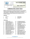
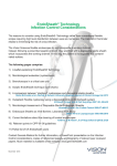
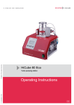
1
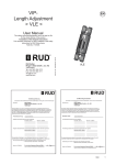
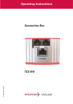
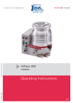
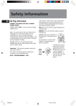
Betriebsanleitung • Operating Instructions
Translation of the Original Operating Instructions
Diaphragm Pump
PK 0202 BE/E (1001)
MVP 015-4
Index
Page
1.
Safety Precautions.......................... 3
1.1. For Your Orientation ......................................... 3
1.2. Pictogram Definitions ....................................... 3
2.
Understanding The Pump.............. 4
2.1 Main Features................................................... 4
2.2. Differences Between The Pump Types............ 4
3.
Installation....................................... 5
3.1. Setting Up The Pump And Location ................. 5
3.2. Connecting The Vacuum Side........................... 5
3.3. Connecting The Exhaust Side........................... 5
3.4. Connecting To Mains Power ............................ 5
4.
Operations....................................... 6
4.1. Important Information....................................... 6
4.2. Switching ON/OFF The Pump .......................... 6
4.2. Intermittent Operations .................................... 6
5.
What To Do In Case Of Breakdown?
...........................................................7
6.
Maintenance.................................... 8
6.1. Precautionary Measures During Maintenance
Work ................................................................. 8
6.2. Cleaning And Replacing Valves And Membranes
.......................................................................... 8
6.3. Dismantling The Pump ..................................... 8
6.4. Assembling The Pump...................................... 8
7.
Service ........................................... 10
8.
Technical Data................................ 11
8.1. Substances Which Come Into Contact With
The Medium ................................................... 11
8.2. Dimensions..................................................... 12
9.
Spare Parts .................................... 12
10. Accessories.................................... 12
Conformity Declaration ........... last page
2
Please note:
Current operating instructions are also available via
www.pfeiffer-vacuum.net.
1. Safety Precautions
☞ Read and follow all the instructions in this manual.
☞ Inform yourself regarding:
☞ Hazards which can be caused by the pump;
☞ Hazards which can arise in your system;
☞ Hazards which can be caused by the medium being
pumped.
☞ Avoid exposing any part of the body to vacuum.
☞ Observe all safety and accident prevention regulations.
☞ Check regularly that all safety requirements are being
complied with.
☞ Do not carry out any unauthorised conversions or
modifications on the pump.
☞ When returning the pump to us please note the shipping
instructions in Section 7.
☞ Do observe strictly the proper use.
Proper use
– The Diaphragm Pump may only be used for the purpose of
generating vacuum.
– Do not pump corrosive or explosive gases.
– Do not pump liquids.
– Do not operate the pump in locations where there is an
explosion hazard.
– Accessories other than those named in this manual may
not be used without the agreement of Pfeiffer Vacuum.
– Do not use the connecting line between the heads of the
pump as a handle.
– Equipment must be connected only to a suitable fused and
protected electrical supply and a suitable earth point.
– Ensure that installation is in compliance with limitations
from the degree of protection, see section “Technical
Data“.
1.1. For Your Orientation
Instructions in the text
➡ Operating instructions: Here you have to do something!
Symbols used
The following symbols are used throughout in the
illustrations:
Vacuum flange
Exhaust flange
Power supply connection
Position numbers
Identical components and accessories parts have the same
position numbers in all illustrations.
1.2. Pictogram Definitions
Danger of personal injury.
WARNING
Danger of damage to the pump or system.
CAUTION
Danger of burns from touching hot parts.
WARNING
Danger of an electric shock.
WARNING
PLEASE NOTE
Attention to particularly important information
on the product, handling the product, or to a
particular part of the documentation.
☞
Improper Use
The following are regarded as improper:
– The pumping of corrosive gases (except with corrosive
gas processes version).
– The pumping of explosive gases.
– Operating the pump in locations where there is an explosion hazard (a special version for this application is
available on request).
– The pumping of gases which are contaminated with
particles, dust and condensate.
– The Pump may not be used for the purpose of generating
pressure.
– The pumping of liquids.
– Connection to pumps and units which is not permitted
according to their operating instructions.
– Connection to units which contain touchable and voltage
carrying parts.
Improper use will cause any rights regarding liability and
guarantees to be forfeited.
Modifications reserved
3
2. Understanding The Pump
2.1. Main Features
2.2. Differences Between The Pump Types
Diaphragm Vacuum Pump MVP 015-4
Features
1
2
3
4
5
6
7
9
Volume flow rate at
1000 mbar and 50 Hz
Pump stages
Connection of the
membrane heads
Final pressure at 50 Hz
Mains connection
Membrane head 1
Membrane head 2
Membrane head 3
Membrane head 4
Vacuum flange (direct screw joint
Voltage supply
Exhaust (silencer)
Capacitor
7
4
9
6
3
MVP 015-4
5
1
2
The diaphragm pump can be applied in all areas where an oilfree, dry vacuum is required.
Particularly the pump is suitable as backing pump for many
Pfeiffer Vacuum turbopumps in applications involving light
gas loads only.
Further applications:
– Pumping stations
– Plants
Research
Laboratories
Analytical
Chemistry
Leak detection
4
Unit
l/min
MVP 015-4
15
four-stage
1-->2 in series
3-->4 in series
mbar
< 0.5
Connecting cable hard-wired in
terminal box, without mains switch
3. Installation
3.1. Setting Up The Pump And Location
➡ Place pump on a smooth, even surface.
➡ Anchor the pump if it is to be erected in a stationary position.
➡ Avoid mechanical stresses due to rigid connections. Insert
elastic hoses or resilient elements as couplings between
the pump and rigid pipes.
➡ Anchoring is not necessary if the pump is not erected in a
stationary position.
➡ Maximum ambient temperature +12 ... +40 °C.
➡ Where rack installation is involved, ensure adequate ventilation. If pump is installed above 1000 m above mean sea
level check compatibillity with applicable safety requirements, e. g. DIN VDE 0530 (motor may overheat due to
insufficient cooling).
CAUTION
Pump versions where the thermostatic winding
protection protrudes must be appropriately
wired to ensure the motor is protected.
Normal version
Motor
3.2. Connecting The Vacuum Side
– Remove locking cap on intake connection.
– Make connection between the vacuum system and pump
as short as possible.
– Connect pump with intake connection to the apparatus.
– If liquid - which would generate vapours - is present in the
system to be evacuated, a condensate trap must be fitted
upstream of the pump.
3.3. Connecting The Exhaust Side
Pressure can rise to dangerous levels in exhaust
lines. Therefore, lay exhaust side lines without
shut-off units. Do not connect the exhaust side
with a closed system on account of the danger
of bursting.
In certain applications, exhaust gases and vapours can be
very hot and represent a health and/or environment hazard.
Lay lines from the pump sloping downwards so that
condensate cannot run back into the pump, otherwise fit a
separator.
CAUTION
3.4. Connecting To Mains Power
The pump is driven by AC motors with the following possible
variants:
230 V + 5% / -10%, 50 Hz
120 V + 5% / -10%, 60 Hz
WARNING
Power connections must comply with local
regulations. Voltage and frequency information
given on the rating plate must correspond to the
mains voltage and frequency values. The pump
may only be connected to mains current with
earthed conductor.
5
4. Operations
4.1. Important Information
CAUTION
Before starting, ensure that impermissibly high
pressures cannot build up on the pressure side.
Interchanging the connections causes
dangerous excess pressure levels.
The pumps should only start, when the pressure difference is max. 1 bar between admission and exhaust,
because the motor will be blocked and damage.
WARNING
When the pump is running, surfaces and motor
casing become hot.
4.3 Intermittent Operations
To prolong the life of diaphragm pumps, intermittent
operations can be selected with lesser gas throughputs of
< 0.18 mbar l/s. This means that, dependent on the turbo
pump power take-up, the backing pump will be switched on
and off. Turbo pump power take-up is dependent on the forevacuum pressure and gas throughput.
– By comparing the power take-up with an upper and a
lower limit value, the relative switch-on duration with
lesser gas throughputs can be reduced to approx. 1 to 60%
– To avoid too frequent switching on, the buffer volume in
the fore-vacuum line should amount to < 0.5 liter from
approx. 0.018 mbar l/s.
Possible intermittent operations variations are shown in the
following diagram:
4.2 Switching ON/OFF The Pump
The pump can be switched on and off at all times.
CAUTION
Prevent internal condensation, transfer of
liquids or dust. The diaphragm and valves will
be damaged, if liquids are pumped in significant
amount over lengthy periods!
If the pump is subjected to condensates it
should be allowed to run for a few minutes
under atmospheric pressure before switching
off.
6
3
4
L
N
PE
PE
N
L´
MVP-Reihe
MVP series
TC
Acc. A
Connection of Diaphragm Pump with relay box (PM 061 372 -T/374-T) on TC for intermittent operations
5. What To Do In The Case Of Breakdowns ?
Problem
Pump does not attain final pressure
Unusual operating noises
Pump does not start
Pump switches off
Possible cause
• Condensate in the pump
Remedy
• Run pump for a longer period under
atmospheric pressure
• Valves/diaphragms defective/dirty • Clean or replace valves and diaphragms,
see section 6.
• Leak in system
• Repair leak
Valves/diaphragms defective
See maintenance in section 6.
Dirt in the working chamber
Clean working chamber.
Silencer loose or missing
Check silencer; clean or replace.
Valves defective
Change valves.
Motor fan defective
Change motor fan.
Con-rod or motor bearing defective
Inform Pfeiffer-Service.
No mains voltage
Check power supply.
Phase failure
Check fuse.
Motor overheating
Allow the motor to cool down and
depress mains switch off/on.
Ambient temperature < 12 °C
Warm pump.
Dirty valves/diaphragms
See maintenance in section 6.
Over-pressure in the exhaust line
Open exhaust line (open exhaust valve).
• Sticking diaphragms
• Clean pump (see section 6.)
• Wrong mains voltage
• Correct as per rating plate
7
6. Maintenance
6.1. Precautionary Measures During
Maintenance Work
CAUTION
Whenever working on the pump ensure the
motor cannot get switched on.
If necessary, remove pump from the system for
inspection. Before dismantling allow the pump
to cool down.
➡ Only dismantle the pump as far is necessary to effect
repairs.
➡ Use only benzin or the like for cleaning. Do not use
solvents.
6.2. Cleaning And Replacing Valves And
Membranes
Under normal operating conditions, the pump is maintenance
free. The valves and the diaphragms are wear parts. If the
rated ultimate vacuum is no longer achieved, the pump interior, the diaphragms and the valves must be cleaned and the
diaphragms and valves must be checked for cracks or other
damage.
Depending on individual cases it may be efficient to check
and clean the pump heads on a regular basis. In case of
normal wear the lifetime of the diaphragms and valves is >
10000 operating hours.
CAUTION
There can be different numbers of washers 17
in each membrane head. Ensure the correct
assignment for mounting when dismantling the
membrane heads. Don’t confuse the washers
17.
6.3. Dismantling The Membrane Head
➡ Allow the pump to cool down before dismantling.
➡ Using an SW 14 key, unscrew direct screw joint (20) of
interhead connection (10) on diaphragm head 1 (see marks
on the housing).
➡ As far as possible place pump on its side so that the head
to be dismantled points up.
➡ Using an SW 3 key, unscrew the four Allan head screws
(11) and remove head cover (12), taking care with the two
valve plates (13) and sealing rings (14).
➡ Remove intermediate plate (15).
➡ Use a small screwdriver to carefully ease out diaphragm
(16) and manually unscrew from the connecting rod (righthand thread). Look out for possible washers (17).
➡ Clean all parts with alcohol and examine diaphragms,
valves and seals for possible damage and renew as
necessary. If a new diaphragm is to be fitted, the washers
(17) of the old diaphragm must be used again otherwise
the pump will not attain the required pressure.
8
6.4. Assembling The Membrane Head
➡ Assemble all parts in reverse order. The connecting rod
should be positioned in the upper dead point when fitting
the diaphragm. Ensure correct positioning of all parts.
➡ Check correct sealing ring seating.
➡ Re-make hose connection and re-tighten direct screw
joint (20).
➡ Test pump for function.
Dismantling the membrane head
11
12
13
14
Allan head screw
Head cover
Valve plate
Sealing ring
11
15
1
2
4
5
7
9
10
10a
11
20
15 Intermediate plate
16 Diaphragm
17 Washer
12
13
16
17
14
Membrane head 1
Membrane head 2
Membrane head 4
Vacuum flange (direct screw
joint)
Exhaust (silencer)
Capacitor
Interhead connection 1-2
Interhead connection 2-3
Allan head screw
direct screw joint
1
11
9
20
10
4
2
10a
7
1
5
9
Do Make Use Of Our Service Facilities
In the event that repairs are necessary to your pumping
station, a number of options are available to you to ensure
any system down time is kept to a minimum:
– Have the pump repaired on the spot by our Pfeiffer
Vacuum Service Engineers;
– Return the individual components to the manufacturer for
repairs;
– Replace individual components with a new value
exchange units.
Local Pfeiffer Vacuum representatives can provide full
details.
Returning contaminated units
If contaminated have to be returned for maintenance/repair,
the following instructions concerning shipping must be
followed:
➡ Neutralise the pump by flushing with nitrogen or dry air.
➡ Seal all openings to the air.
➡ Seal pump or unit in suitable protective foil.
➡ Return equipment only in suitable, rugged shipping
containers and by complying with the currently valid shipping regulations.
Before Returning:
➡ Dismantle all accessories.
➡ Attach a clearly visible notice: “Free of contamination” (to
the unit being returned, the delivery note and accompanying paperwork).
Harmful substances" are substances and preparations as
defined in current legislation. Pfeiffer Vacuum will carry out
the decontamination and invoice this work to you if you have
not attached this note. This also applies where the operator
does not have the facilities to carry out the decontamination
work. Units which are contaminated microbiologically, explosively or radioactively cannot be accepted as a matter of
principle.
☞
7. Service
Fill out the service request and the declaration on
contamination
➡ Download the forms “Service Request” and “Declaration
on Contamination”.1)
➡ Fill out the “Service Request” form and send it by fax or
e-mail to your Pfeiffer Vacuum service address.
➡ Include the confirmation on the service request from Pfeiffer Vacuum with your shipment.
➡ Fill out the contamination declaration and enclose it in the
shipment (required!).
Please get in touch with your local Pfeiffer Vacuum representatives if there are any questions regarding contamination.
WARNING
1)
Decontaminate units before returning or
possible disposal. Do not return any units which
are microbiologically, explosively or radioactively contaminated.
Forms under www.pfeiffer-vacuum.net
10
PLEASE NOTE
Repair orders are carried out according to our
general conditions of sale and supply.
➡ If repairs are necessary, please send the unit together
with a short damage description to your nearest Pfeiffer
Vacuum Service Center.
8. Technical Data
Size
Connections
Intake side
Pressure side
Nominal volume flow rate at 1000 mbar
50 Hz
60 Hz
Volume flow rate at 10 mbar
50 Hz
60 Hz
Final pressure
Permissible exhaust pressure
Leakrate to vacuum chamber
when pump is switched off
Integral Leakrate
Max. operating altitude (a. s. l.)
Max. permissible gas- and
environment temperature
Overload protection
(coiled temperature switch)
Noise level
Motor (insulation material class B)
Power at 230 V 50 Hz
Power at 115 V 60 Hz
Weight, approx.
Unit
MVP 015-4
G 1/8“+silencer
G 1/8“+silencer
l/min
l/min
15
18
l/min
l/min
mbar
mbar
4
4,5
≤ 0.5
1050
mbar l/sec
mbar l/sec
m
≤ 5.10-3
≤ 1.10-3
approx. 2000
°C
+12 ... +40
°C
dB(A)
118
ca. 52
IP 54
80
80
7.5
W
W
kg
8.1. Substances Which Come Into
Contact With The Medium
Pump components
Diaphragm
Valves
Pump head
Tupe
Swivelling screw-fitting
Silencer
Substances in contact with the media
(MVP 015-4)
EPDM
EPDM
Aluminium
PVC
Aluminium
Polyamide
11
8.2. Dimensions
9. Spare Parts
Pos.
7
Description
MVP 015-4
Spare parts pack contains
all necessary wear parts:
Silencer
Pieces
Size
Number
Comments/relevant
2
PU E22 009 -T
1
PO 920 567 E
not included in the
delivery consignment
not included in the
delivery consignmen
Ord. Quantity
When ordering accessories and spare parts please be sure to state the full part number. When ordering spare parts please state
additionally the unit type and unit number (see rating plate). Please use this list as an order form (by taking a copy).
10. Accessories
Description
Relaybox, 1 phas. 5A for
connection to TC 110
Relaybox, 1 phas. 5A for
connection to TC 400
12
Pieces
1
Size
94 x 65 x 57 (mm)
Number
PM 061 372 -T
1
94 x 65 x 57 (mm)
PM 061 374 -T
Comments/relevant
Konformitätserklärung
Declaration of Conformity
nach EG-Richtlinie/according to the EC directive:
- Maschinen/Machinery 2006/42/EG (Anhang/Annex II, Nr. 1 A)
Hiermit erklären wir, dass das unten aufgeführte Produkt allen einschlägigen Bestimmungen der EGMaschinenrichtlinie 2006/42/EG entspricht. Zusätzlich entspricht das unten aufgeführte Produkt allen
einschlägigen Bestimmungen der EG-Richtlinie "Elektromagnetische Verträglichkeit" 2004/108/EG .
Bevollmächtigter für die Zusammenstellung der technischen Unterlagen ist Herr Sebastian Oberbeck,
Pfeiffer Vacuum GmbH, Berliner Straße 43, 35614 Aßlar.
We hereby declare that the product cited below satisfies all relevant provisions of EC Machinery
Directive 2006/42/EC. In addition, the product cited below satisfies all relevant provisions of EC Directive
"Electromagnetic Compatibility" 2004/108/EC .
The agent responsible for compiling the technical documentation is Mr. Sebastian Oberbeck,
Pfeiffer Vacuum GmbH, Berliner Straße 43, 35614 Aßlar.
Produkt/Product:
MVP 015-4
Angewendete Richtlinien, harmonisierte Normen und angewendete, nationale Normen und Spezifikationen/
Guidelines, harmonised standards and national standards and specifications which have been applied:
DIN EN ISO 12100-1 : 2004
DIN EN ISO 12100-2 : 2004
DIN EN 1012-2 : 1996
DIN EN 60335-1 : 2007
DIN EN 55014-1 : 2007
DIN EN 55014-2 : 2009
DIN EN 61000-3-2 : 2006
DIN EN 61000-3-3 : 2009
Unterschriften/Signatures:
Pfeiffer Vacuum GmbH
Berliner Str. 43
35614 Asslar
Germany
Unterschriften:
(M. Bender)
Geschäftsführer
Managing Director
(Dr. M. Wiemer)
Geschäftsführer
Managing Director
CE/2010
Vacuum is nothing, but everything to us!
Turbopumps
Rotary vane pumps
Roots pumps
Dry compressing pumps
Leak detectors
Valves
Components and feedthroughs
Vacuum measurement
Gas analysis
System engineering
Service
Pfeiffer Vacuum Technology AG · Headquarters/Germany
Tel. +49-(0) 64 41-8 02-0 · Fax +49-(0) 64 41-8 02-2 02 · [email protected] · www.pfeiffer-vacuum.net