1
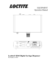
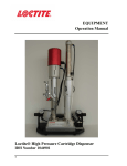
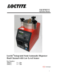
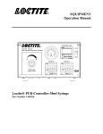
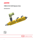
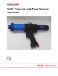
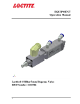
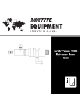
EQUIPMENT Operation Manual Loctite® Rotary Dispense System Part Number 1176443 1 Table of Contents 1. PLEASE OBSERVE THE FOLLOWING........................................................................................................3 1.1 EMPHASIZED SECTIONS .......................................................................................................................................3 2. DESCRIPTION ...................................................................................................................................................3 2.1 2.2 2.3 2.4 2.5 2.6 3. OPERATION ..........................................................................................................................................................3 THEORY OF OPERATION .......................................................................................................................................4 ITEMS SUPPLIED ...................................................................................................................................................4 OVERALL DIMENSIONS ........................................................................................................................................5 CONTROL PANEL (FRONT OF CONTROLLER) ........................................................................................................6 INTEGRATION PANEL (BACK OF CONTROLLER) ...................................................................................................6 TECHNICAL DATA...........................................................................................................................................7 3.1 SPECIFICATIONS ...................................................................................................................................................7 4. INSTALLATION.................................................................................................................................................8 4.1 UNPACKING AND INSPECTION ..............................................................................................................................8 4.2 INSTALLATION .....................................................................................................................................................8 4.3 DISPENSER INTEGRATION ....................................................................................................................................9 4.3.1 Syringe or Cartridge Dispensing .................................................................................................................9 4.3.2 98009 Light Cure and 98013 Cyanoacrylate Dispense Valves..................................................................10 4.3.3 97113 and 97114 Stationary Valves ..........................................................................................................10 5. OPERATION .....................................................................................................................................................11 5.1 AUTO MODE ........................................................................................................................................................11 5.2 MANUAL PRIME MODE ........................................................................................................................................11 5.3 SLIDE ADJUSTMENTS ...........................................................................................................................................11 5.3.1 Slide Speed Control Adjustment .................................................................................................................11 5.3.2 Slide Stroke Adjustment ..............................................................................................................................12 5.4 RESERVOIR LOW LEVEL CONTROL ......................................................................................................................12 5.4.1 Bypass the Low Level Function ..................................................................................................................12 5.4.2 Activate the Low Level Function.................................................................................................................12 6. TROUBLESHOOTING ....................................................................................................................................13 7. CARE AND MAINTENANCE.........................................................................................................................13 7.1 CARE .................................................................................................................................................................13 7.2 MAINTENANCE ..................................................................................................................................................13 8. DOCUMENTATION ........................................................................................................................................14 8.1 ELECTRICAL SCHEMATIC ...................................................................................................................................14 8.2 FOOT SWITCH SCHEMATIC ...............................................................................................................................155 9. ACCESSORIES AND SPARE PARTS ...........................................................................................................15 EQUIPMENT WARRANTY............................................................................................................................16 2 1. Please Observe The Following 1.1 Emphasized Sections Warning! Refers to safety regulations and requires safety measures that protect the operator or other persons from injury or danger to life. Caution! Emphasizes what must be done or avoided so that the unit or other property is not damaged. Notice: Gives recommendations for better handling of the unit during operation or adjustment as well as for service activities. 2. Description 2.1 Operation The Loctite® Rotary Dispense System is used for dispensing adhesives onto a customer’s part in a circular or arc pattern. It is a fully integrated system that will control a syringe system, cartridge, or dispense valve (no separate valve controller is required). Internally synchronized operation of an advancing slide, turntable, and dispense timer makes for easy and repetitive placement of the adhesive. The set-up is simple, using only a timer and motor speed adjustment (no complex programming!). 3 2.2 Theory of Operation 1. 2. Press the footswitch to activate the system. The advancing slide will start to extend and the rotary disc will start to rotate with the preset speed. The advancing slide will activate the proximity sensor when it reaches the preset position. When the magnet on the rotary disc reaches the proximity sensor, the dispensing timer will be activated and start to dispense with preset dispensing time. This design confirms each start of dispensing will be at the same point. (An adjustable part fixture is recommended below as a reference) After the dispensing timer has reached the preset dispensing time, the advancing slide will retract and the rotary disc will be stopped. 3. 4. 5. The reservoir low level alarm indicator (1) will light when the low level sensor on the reservoir provides a low level signal. Recommended “Adjustable” Part Fixture allows adjustment of the adhesive bead start position: 2.3 Items Supplied (1) Rotary Dispense System (1) Footswitch (1) Power Adapter with Cord (2) M4 Screws for Mounting Rail (1) Manual 4 2.4 Overall Dimensions 5 2.5 Control Panel (Front of Controller) 7 5 4 1 2 3 6 2.6 Integration Panel (Back of Controller) 14 18 8 9 10 11 12 15 1. 2. 3. 4. 5. 6. 7. 8. 9. Reservoir Low Level Alarm Indicator Manual Prime Button Mode Switch Dispense Timer Tachometer (Speed in 1/10rpm) Rotary Speed Adjust Knob Dispense Start Up Sensor Rotary Disc Speed Sensor Advance Slide Limit Switch Connector 16 17 10. 11. 12. 13. 14. 15. 16. 17. 18. 13 Aux Device Start Output Connector Low Level Sensor Switch Low Level Sensor (XS2) Connector Start Switch (XS1) Connector Stand Assembly Fixing Screw Stand Assembly Fixing Screw Power Input Main Power Switch Manifold and Solenoid Valves 6 3. Technical Data 3.1 Specifications Attribute Dispense Pattern Slide Stroke (for valve or syringe) Time Range Rotation Speed Maximum Part Height Maximum Part Diameter Maximum Part Weight Dimensions Width Depth Height Weight Air Input* Power * Value Circles or Arcs in a Circular Pattern 0 – 2” (0 – 50 mm) 0 – 99.99 seconds 5 to 110 RPM 12” (305 mm) 8.5” (216 mm) 8.8 lbs (4 kg) 13” (330 mm) 11¾” (297 mm) 22½”” (572 mm) Minimum 25” (635 mm) Maximum 26.5 lb (12 kg) Clean, dry air not to exceed 125 psig (8.5 bar), and filtered with a maximum of 50 micron Supply: 110 – 230 V / 50 – 60 Hz Internal: 24 VDC Power Connection: Includes plug ends for North America/Japan, Continental Europe, UK, Australia and China. If the required air quality is not achieved, install a Loctite® filter regulator. In the US order a 5 μm filter using part number 985397. In Europe or Asia, order a 10 μm filter using part number 97120. 7 4. Installation 4.1 Unpacking and Inspection Carefully remove the system from its shipping carton and inspect it for any signs of damage. Any damage should be reported immediately to the carrier. Refer to the list of supplied parts (see page 4) and compare to the contents. Report any missing or damaged parts promptly to the Henkel customer service department at 1-800-LOCTITE (562-8483). 4.2 Installation 1. 2. Assemble the stand to the main control unit. 1 Fix the stand assembly by the M10 screw from the bottom (15) 2 and the M5 from the rear side (14) of the control unit. 3 Assemble the slide assembly to the stand. 4 Fix the slide assembly by the M6 screw. 5 Plug the power adapter with cord into the back of the controller (16) and into the wall socket. Notice: The power adapter has auto ranging power function that can be used with either 110 or 220V and 50 or 60 Hz. Connect the foot switch to the back of the controller (13). Connect the air input line to the system (18) by using 6mm outer diameter pneumatic tubing (not supplied). Turn on the air input. This must be a minimum of 80 psi and a maximum of 125 psi. 3. 4. 5. 6. 7. 8. 5 4 1 Warning! When the air is connected, the slide may retract. Be sure to keep your hands and other objects clear of the slide before connecting 3 the air. 2 Caution! Clean, dry, filtered air must be used. If it is not, the solenoids in the controller will be fouled over time. If the required air quality is not achieved, install a Loctite® filter regulator. In the US order a 5 μm filter using Part Number 985397. In Europe or Asia, order a 10 μm filter using Part Number 97120. 8 4.3 Dispenser Integration The Loctite® Rotary Dispense System is designed to be used with syringes, cartridges, single acting product valves and double acting product valves. To integrate these dispense systems please use the following instructions: 4.3.1 Syringe or Cartridge Dispensing Must be purchased separately: Loctite Part Number Syringe 10 ml 30 ml Syringe Dispenser (Required) 883976 883976 3 ¾” Mounting Rail (required) 98328 98328 Mounting Bracket (required) 98316 98316 Syringe Adapter (required) 98320 N/A Dispense Tip Connectors (required) N/A N/A 55 ml 883976 98328 98316 N/A N/A Clear Syringe Barrel Kit (optional) Black Syringe Barrel Kit (optional) 98314 98315 Accessory 1. 2. 3. 4. 5. 6. 7. 8. 9. 10. 97207 97263 97244 97264 Cartridge 300 ml 883976 98328 98318 N/A 982644 97233 N/A N/A Refer to the operation manual of the syringe dispenser for setup instructions. Connect the syringe dispenser to the system with XS2 cable part number 989432 (need to purchase separately). Insert the 4mm tube plug in the both “DISPENSE OFF” and “DISPENSE ON” connection. Add the dispense tip onto the syringe or cartridge. For some cartridges, it will be necessary to install the cartridge adapter Part No. 982644 and luer lock adapter Part No. 97233 before connecting the dispense tip. Secure the mounting rail to the advance slide by the M4 screws provided. Slide the mounting bracket over the mounting rail on the slide assembly and secure it in position with the white nylon thumbscrew. Manually pull the slide down to the fully extended position. Adjust the height and position of the mounting bracket to the approximate position desired. To adjust the position, loosen the hexagon screws on the clamp blocks counter clockwise, set the position and then secure by turning the hexagon screws clockwise. Slide the syringe or cartridge into the mounting bracket and secure it using the black thumbscrews. Caution! It is important to ensure that the dispense tip will not crash with the mounting plate, fixture or part. Please ensure that the height is set to avoid crashes. The rotary dispense system is now ready to be used. 9 4.3.2 98009 Light Cure and 98013 Cyanoacrylate Dispense Valves Must be purchased separately: • Mounting Rail – P/N 98328 • Mounting bracket – P/N 98326 • Pressure Reservoir - P/N 982726, Bond-A-Matic reservoir, 0-15 psi for use with adhesives with <3,000 cPs viscosity. - P/N 982727, Bond-A-Matic reservoir, 0-100 psi for use with adhesives with >3,000 cPs viscosity. 1. 2. 3. 4. 5. 6. 7. 8. 9. Insert the 4mm tube plug in the “DISPENSE OFF” connection. Add the dispense tip onto the valve. Secure the mounting rail to the advance slide by the M4 screws provided. Slide the mounting bracket over the mounting rail on the slide assembly and secure it in position with the white nylon thumbscrew. Manually pull the slide down to the fully extended position. Slide the valve into the mounting bracket and secure it using the black thumbscrews. Adjust the height and position of the mounting bracket to the approximate position desired. To adjust the position, loosen the hexagon screws on the clamp blocks counter clockwise, set the position and then secure by turning the hexagon screws clockwise. Caution! It is important to ensure that the dispense tip will not crash with the mounting plate, fixture or part. Please ensure that the height is set to avoid crashes. Connect the air inlet on the valve to the “DISPENSE ON” on the back of the controller using the 4mm air line tubing supplied with the valve. The rotary dispense system is now ready to be used. 4.3.3 97113 and 97114 Stationary Valves Must be purchased separately: • Mounting Rail – P/N 98328 • Mounting bracket – P/N 98327 • Pressure Reservoir - P/N 982726, Bond-A-Matic reservoir, 0-15 psi for use with adhesives with <3,000 cPs viscosity. - P/N 982727, Bond-A-Matic reservoir, 0-100 psi for use with adhesives with >3,000 cPs viscosity. 1. Connect the “DISPENSE ON” and “DISPENSE OFF” from the valve to the back of the controller using the 4mm air line tubing supplied with the valve. 2. Add the dispense tip to the valve. 3. Secure the mounting rail to the advance slide by the M4 screws provided. 4. Slide the mounting bracket over the mounting rail on the slide assembly and secure it in position with the white nylon thumbscrew. 5. Manually pull the slide down to the fully extended position. 6. Slide the valve into the mounting bracket and secure it using the black thumbscrews. 7. Adjust the height and position of the mounting bracket to the approximate position desired. To adjust the position, loosen the hexagon screws on the clamp blocks counter clockwise, set the position and then secure by turning the hexagon screws clockwise. Caution! It is important to ensure that the dispense tip will not crash with the mounting plate, fixture or part. Please ensure that the height is set to avoid crashes. 8. The single rotary dispense station is now ready to be used. 10 5. Operation 5.1 Auto Mode 1. Turn the “POWER” on (the position marked “ ( )” ׀17). The dispense timer (4) and tachometer (5) will turn on. If necessary, open the valve or regulator that controls the air inlet to supply pneumatic pressure to the system. 2. 3. 4. 5. 6. 7. 8. Warning! When the air is turned on, the slide may retract. Be sure to keep your hands and other objects clear of the slide before resetting the emergency stop. If you have not already installed a syringe, cartridge or dispense valve, do so now. See Section 4.3 for instructions. Test the dispense rate, switch the mode switch (3) to Manual Prime Mode and press the Manual Prime Switch (2) to purge the adhesive. Switch the mode switch (3) back to the Auto Mode. Notice: A receptacle should be placed under the dispense tip to capture purged product. Set the dispensing time by adjusting the dispense timer (4) from 0 – 99.99 seconds. Set the speed of the rotary disc by adjusting the Rotary Speed Adjust Knob (6). Press the footswitch to activate the system. 5.2 Manual Prime Mode 1. 2. Switch the mode switch (3) to Manual Prime Mode. Press the Manual Prime Switch (2) to purge the adhesive 5.3 Slide Adjustments 5.3.1 Slide Speed Control Adjustment The speed controls on the slide can be adjusted to increase or decrease the speed that the slide advances or retracts. It recommended for the speed controls be set so that the slide moves at a controlled rate. This may need to be adjusted to account for more weight on the slide or to change the slide advance / retract time. Adjust Slide Advance Rate Here Adjust Slide Retract Rate Here 11 5.3.2 Slide Stroke Adjustment The factory default for the slide stroke is the 2” (which is the maximum stroke). When setting up a new process, it is recommended that dispense tip be positioned using the clamps on the stand, not by adjusting the slide stroke. This will ensure that dispense tip is as far away from the part as possible when retracted to avoid collisions when loading and unloading parts. The slide stroke should only be adjusted when the time required to advance and retract the slide results in an unacceptable cycle time. This should be a rare occurrence. To minimize the slide advance and retract times, the speed controls should first be adjusted (see Section 5.3.1). If this does not reduce the cycle time sufficiently, the slide stroke can be reduced using the following procedure. 1. 2. 3. 4. 5. Switch off the system and turn off the pneumatic supply to the system. Fully extend the advance slide manually. Adjust the slide stroke by adjusting the nut shown as below figure. Release the advance slide. The system is ready to use. Adjust Slide Stroke Here 5.4 Reservoir Low Level Control 5.4.1 Bypass the Low Level Function 1. Switch the Low Level Sensor Switch to “Bypass” 5.4.2 Activate the Low Level Function 1. Connect the 9 pins D-sub female (XS2 Low Lev) cable the to the Low Level Sensor (XS2) Connector (12) 2. Switch the Low Level Sensor Switch to “Active” 12 6. Troubleshooting Symptom Possible Corrective Action(s) The “POWER” does not “ON” 1. 2. The system will not pressurize. 1. 2. 3. The dispense valve does not dispense 1. 2. 3. Plug the unit in Set the “POWER” button (17) in the “ ” ׀ position Confirm that the “AIR IN” is connected Confirm that the air supply is 80-125 psi. Confirm that the “DISPENSE ON” and “DISPENSE OFF” fittings are properly connected or plugged. The slide is advancing or retracting too fast or slow. The slide advance and retract rate should be set so that the slide moves at a controlled rate. The factory default is for the full slide stroke to take approximately 0.5 seconds. If this needed to be adjusted, see Section 5.3 for instructions. The “Reservoir Low Level Alarm Light” (1) does 1. Check that XS2 cable between the reservoir and not work the system is connected 2. Check that Low Level Sensor Switch (11) is in “active” position 7. Check the pneumatic connection Check the pneumatic supply Check the dispense start up sensor (7) is working normally Care and Maintenance 7.1 Care This unit should be stored in a level, dry location at ambient condition out of direct sunlight. 7.2 Maintenance To minimize wear of the slide assembly, periodically apply several drops of light machine oil to the slide rods, manually advance and retract the slide several times then remove the excess lubricant using a rag. Warning! Be sure to release the pressure and shut of the pressure supply before lubricating the slide rods. Clean, dry, filtered air must be used. If it is not, the solenoids on the controller will be fouled over time. Notice: If the required air quality is not achieved, install a Loctite® filter regulator. In the US order a 5 μm filter using Part Number 985397. In Europe or Asia, order a 10 μm filter using Part Number 97120. 13 8. Documentation 8.1 Electrical Schematic 14 8.2 Foot Switch Schematic 9. Accessories and Spare Parts Loctite Item Number Accessories 98328 98316 98320 98318 98326 98327 98406 98441 883976 985397 97201 Description 3 ¾” Mounting Rail 30ml Syringe Mounting Bracket Kit 10ml adapter for use with 98316 300ml Cartridge Mounting Bracket Kit 98009 and 98013 Valve Mounting Bracket Kit 97113 and 97114 Valve Mounting Bracket Kit 983914 and 986300 Poppet Valve Mounting Bracket Kit 98520 Spray and 98084 Micro Needle Valve Mounting Bracket Kit Loctite® Digital Syringe Dispenser Loctite® Air Filter, Regulator, Gauge Loctite® Foot Switch 15 EQUIPMENT WARRANTY For Loctite® Rotary Dispense System Henkel expressly warrants that all products referred to in this Instruction Loctite® Rotary Dispense System (hereafter called “Products”) shall be free from defects in materials and workmanship. Liability for Henkel shall be limited, at its option, to replacing those Products which are shown to be defective either in materials or workmanship or to credit to the purchaser the amount of the purchase price thereof (plus freight and insurance charges paid therefore by the user). The purchaser’s sole and exclusive remedy for breach of warranty shall be such replacement or credit. A claim of defect in materials or workmanship in any Products shall be allowed only when it is submitted to Henkel in writing within one month after discovery of the defect or after the time the defect should reasonably have been discovered and in any event, within twelve months after the delivery of the Products to the purchaser. No such claim shall be allowed in respect of Products which have been neglected or improperly stored, transported, handled, installed, connected, operated, used or maintained or in the event of unauthorized modification of the Products including, where products, parts or attachments for use in connection with the Products are available from Henkel, the use of products, parts or attachments which are not manufactured by Henkel. No Products shall be returned to Henkel for any reason without prior written approval from Henkel. Products shall be returned freight prepaid, in accordance with instructions from Henkel. NO WARRANTY IS EXTENDED TO ANY EQUIPMENT WHICH HAS BEEN ALTERED, MISUSED, NEGLECTED, OR DAMAGED BY ACCIDENT, OR IF THE SYSTEM USED TO DISPENSE ANY LIQUID ® MATERIAL OTHER THAN LOCTITE PRODUCTS. EXCEPT FOR THE EXPRESS WARRANTY CONTAINED IN THIS SECTION, HENKEL MAKES NO WARRANTY OF ANY KIND WHATSOEVER, EXPRESS OR IMPLIED, WITH RESPECT TO THE PRODUCTS. ALL WARRANTIES OF MERCHANTABILITY, FITNESS FOR A PARTICULAR PURPOSE, AND OTHER WARRANTIES OF WHATEVER KIND (INCLUDING AGAINST PATENT OR TRADEMARK INFRINGEMENT) ARE HEREBY DISCLAIMED BY HENKEL AND WAIVED BY THE PURCHASER. THIS SECTION SETS FORTH EXCLUSIVELY ALL OF LIABILITY FOR HENKEL TO THE PURCHASER IN CONTRACT, IN TORT OR OTHERWISE IN THE EVENT OF DEFECTIVE PRODUCTS. WITHOUT LIMITATION OF THE FOREGOING, TO THE FULLEST EXTENT POSSIBLE UNDER APPLICABLE LAWS, HENKEL EXPRESSLY DISCLAIMS ANY LIABILITY WHATSOEVER FOR ANY DAMAGES INCURRED DIRECTLY OR INDIRECTLY IN CONNECTION WITH THE SALE OR USE OF, OR OTHERWISE IN CONNECTION WITH, THE PRODUCTS, INCLUDING, WITHOUT LIMITATION, LOSS OF PROFITS AND SPECIAL, INDIRECT OR CONSEQUENTIAL DAMAGES, WHETHER CAUSED BY NEGLIGENCE FROM HENKEL OR OTHERWISE. Henkel Corporation One Henkel Way Rocky Hill, CT 06067-3910 USA Henkel Canada Corporation 2225 Meadowpine Boulevard Mississauga, Ontario L5N 7P2 CANADA Henkel Corporation Automotive/ Metals H.Q. 32100 Stephenson Hwy, Madison Heights 48071 USA Henkel Capital, S.A. de C.V. Calzada de la Viga s/n Fracc. Los Laureles Loc. Tulpetlac, C.P. 55090 Ecatepac de Morelos, MEXICO Henkel Singapore Pte Ltd 401 Commonwealth Dr. #03-01/02 Har Par Technocentre Singapore 149598 Henkel (China) Company Ltd. No. 928 Zhang Heng Road, Zhangjiang, Hi-Tech Park, Pudong, Shanghai, China 201203 Henkel Loctite Korea 8F, Mapo Tower, 418, Mapo-dong, Mapo-gu, Seoul, 121-734, KOREA Henkel Japan Ltd. 27-7 Shin Isogo-cho, Isogo-ku Yokohama, 235-0017 JAPAN www.equipment.loctite.com Loctite is a trademark of Henkel Corporation, U.S.A. © Copyright 2006. Henkel Corporation Teflon is a registered trademark of E.I. DuPont de Nemours Co., Inc. All rights reserved. Data in this operation manual is subject to change without notice. Manual P/N: 8901839 Rev B, Date: 07/2009 16