1
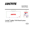
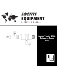
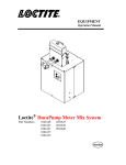
EQUIPMENT
Operation Manual
Loctite® High Pressure Cartridge Dispenser
IDH Number 1046901
1
TABLE OF CONTENTS
1. PLEASE OBSERVE THE FOLLOWING .................................................................................................. 3
1.1
1.2
1.3
1.4
1.5
EMPHASIZED SECTIONS ............................................................................................................ 3
ITEMS SUPPLIED ........................................................................................................................ 3
FOR YOUR SAFETY.................................................................................................................... 3
FIELD OF APPLICATION, (INTENDED USAGE)............................................................................ 4
UNPACKING AND INSPECTION ................................................................................................... 4
2. DESCRIPTION .............................................................................................................................................. 4
2.1 THEORY OF OPERATION....................................................................................................................... 4
2.2 DISPENSER COMPONENTS ................................................................................................................... 5
3. TECHNICAL DATA....................................................................................................................................... 6
3.1
3.2
3.3
3.4
3.5
3.6
3.7
3.8
3.9
SIZE ........................................................................................................................................... 6
WEIGHT ..................................................................................................................................... 6
INPUT VOLTAGE ........................................................................................................................ 6
RATED POWER .......................................................................................................................... 6
DISPENSING PRESSURE ............................................................................................................. 6
OPERATING TEMPERATURE ...................................................................................................... 6
AIR CONSUMPTION ................................................................................................................... 6
PUMP CYCLE RATE ................................................................................................................... 6
ADHESIVE VISCOSITY ............................................................................................................... 6
4. INSTALLATION............................................................................................................................................. 6
4.1
4.2
4.3
4.4
4.5
4.6
CONNECTING THE UNIT AIR AND POWER SUPPLY ................................................................... 6
CONNECTING A DISPENSE CONTROLLER.................................................................................. 6
SETTING THE LOW LEVEL SENSOR (FOR 97102 CONTROLLER) ............................................... 7
INSTALLATION OF CARTRIDGE INSERT .................................................................................... 7
CONNECTING THE FEEDLINE AND VALVE................................................................................ 7
PUMP LUBRICATION .................................................................................................................. 7
5. OPERATING THE UNIT............................................................................................................................... 8
5.1
5.2
5.3
5.4
5.5
INSTALLING THE ADHESIVE CARTRIDGE.................................................................................. 8
PRIMING THE RESERVOIR BLOCK ............................................................................................. 8
PRIMING THE PUMP................................................................................................................... 8
PRIMING THE FEEDLINE AND DISPENSING ............................................................................... 9
ADJUSTING DISPENSE RATE...................................................................................................... 9
6. CARE AND MAINTENANCE ................................................................................................................ 9-10
7. ELECTRICAL WIRING DIAGRAM ........................................................................................................ 11
8. TROUBLESHOOTING .......................................................................................................................... 11-12
9. ACCESSORIES AND SPARE PARTS ................................................................................................... 133
2
1.
1.1
Please Observe the Following
Emphasized Sections
WARNING!
Refers to safety regulations and required measures that protect the operator or other
persons from injury or danger to life.
Caution!
Emphasizes what must be done or avoided so that the unit or other property is not
damaged.
Notice:
Gives recommendations for better handling of the unit during operation or adjustment,
as well as for service activities.
1.2
Items Supplied
1
High Pressure Cartridge Dispenser
2
Cartridge Adaptor Inserts
1
PTFE Lined Stainless Steel Braided Feedline (2m Length)
1
Power Cord
1
XS2 Connection Cable
1
Low Level Sensor with Cable (1m Length) – Already Installed
1
Air Supply Line (2m Length)
1
Lubricant Oil
1
Operation Manual
1.3
For Your Safety
For safe and successful operation of the unit, read these instructions completely. If the
instructions are not observed, the manufacturer can assume no responsibility. Be sure
to retain this manual for future reference.
Damage to the power cable and electrical junction box can result in contact with live
electrical circuits. Check for damage to the electrical circuit before each use. If the unit
is damaged, do not operate.
Do not expose the power cable to heat, oil, or sharp edges.
Make sure the dispenser stands stable and secure.
Use only Loctite® original equipment replacement parts.
Always disconnect the power supply before servicing the unit.
Observe general safety regulations for the handling of chemicals such as Loctite®
adhesives and sealants. Observe the manufacturer instructions as stated in the Material
Safety Data Sheet (MSDS).
While under warranty, the unit must be repaired by an authorized Loctite® brand
service representative.
3
1.4
Field of Application, (Intended Usage)
The Loctite® High Pressure Cartridge Dispenser is designed for dispensing high
viscosity 1-component adhesives and sealants. Compatible Loctite® product chemistries
include: Silicone, Polyurethane and MS polymer adhesives. The dispenser can be used
as a manual dispenser or integrated with a controller and dispensing valve for
automated dispensing.
1.5
Unpacking and Inspection
Carefully unpack the Loctite® High Pressure Cartridge Dispenser and examine the
items contained in the carton. Inspect the unit for any damage that might have occurred
in transit. If such damage has occurred, notify the carrier immediately. Claims for
damage must be made by the consignee to the carrier and should be reported to the
manufacturer.
2.
2.1
Description
Theory of Operation
The Loctite® High Pressure Cartridge Dispenser is an integrated system for dispensing
high viscosity materials packaged in 300ml cartridges.
The cartridge dispenser consists of three main components: the pneumatic priming ram,
adhesive reservoir block and the 10:1 pump. The pneumatic ram is used to provide a
low pressure feed of adhesive to the reservoir block. The 10:1 pump draws product
from the reservoir block and amplifies the pressure by a factor of 10 and feeds the
product through a feedline to the valve.
The unit has two regulators to control the pressure of the pneumatic priming ram and
the 10:1 pump. By increasing the pressure of either of these regulators the outlet
pressure of the dispenser will be increased. The primary product regulation should be
controlled using the pump regulator and the pneumatic ram regulator should be set to
supply product at just enough pressure to feed the reservoir.
The 110 – 240VAC power cable plugs to the electrical junction box and supplies power
to the 10:1 pump via the low level relay.
The low level sensor is mounted to the pneumatic priming ram to indicate when the
adhesive cartridge is empty. When activated, the low level sensor will provide a signal
to the COM port on the electrical box and turn the 10:1 pump off.
4
2.2
Dispenser components
7
6
5
8
2
4
1.
2.
3.
4.
5.
6.
7.
8.
5
Cartridge Insert (JPN and Fischbach Cartridge)
Pump Pressure Regulator
Cartridge Pusher Pressure Regulator
Priming Valve
Fluid Outlet
Cartridge Pusher
Pump Tower
Secondary Priming Outlet
1
3
3. Technical Data
Size
Width:
Depth:
Height:
355mm (14”)
210mm (8.3”)
687mm (27”)
Weight
5.0kg (11lb)
Input Voltage
110 – 240 VAC 50/60 Hz
Voltage fluctuation not to exceed 10% of nominal voltage
Rated Power
20W
Air Supply
6bar (85psi) maximum
Dispensing Pressure
50bar (725psi) maximum
Operating Temperature
-20oC to +50oC (-4oF to +120oF)
Air Consumption
0.7 CFM (80 Liter/min) maximum
Pump Cycle Rate
200 cycles/minute maximum
Adhesive Viscosity
10,000 – 1,000,000cPs
4. Installation
4.1 Connecting the unit air and power supply
1. Ensure that the pneumatic priming ram switch is in the “up” position.
2. Connect 5-7bar (70-100 psi) dry, filtered air supply to air inlet fitting. Make sure
the air inlet pressure is at least 5bar (70 psi).
3. Adjust both pump and pneumatic ram regulators to 0 bar.
4. Connect the power supply cable to the electrical junction box and turn the power
switch to the “on” (illuminated) position.
4.2
6
Connecting a dispense controller
1. Connect the controller 97101 per the controller installation procedure.
2. Connect the controller “reservoir” air outlet to the pneumatic fitting on cartridge
dispenser electrical junction box using the supplied air line.
3. Connect the low level sensor cable to connect between the electric junction box
COM port and the 97101 low level sensor input.
4. Installation (continued)
4.3
Setting the low level sensor
1. Insert an empty cartridge into the cartridge holder and screw firmly into the
cartridge insert to enable a positive seal.
2. Assemble the pneumatic ram onto the cartridge holder.
3. Increase the pneumatic ram regulator to 0.5bar (7psi) and move the pneumatic ram
switch to the “down” position.
4. The pneumatic ram should move down the cartridge and activate the low level
sensor. If the low level sensor does not activate, it means that the plunger of the
pneumatic ram needs to be adjusted.
5. Once the low level sensor is activated, unscrew the low level sensor from the side
of the pneumatic ram and move it down until it deactivates. From this position,
move it back in 1-2mm increments until the sensor actives.
6. Tighten the low level sensor screw to maintain this position.
4.4
Installation of cartridge insert
1. Select the cartridge insert that matches the threaded connection of the 300ml
adhesive cartridge being used.
2. Remove the pneumatic ram and then unscrew the cartridge holder from the
reservoir block assembly. This can be accomplished by turning the cartridge holder
in an counter-clockwise direction.
3. Install the cartridge insert into the reservoir block ensuring that the o-ring on the
cartridge insert is facing down (towards the reservoir block). Tighten with the
suitable tool.
4. Replace the cartridge holder.
The pneumatic ram can cause injury when removed from the cartridge holder.
While disassembled, ensure that the air supply is disconnected or the pneumatic
ram regulator is set to a low pressure to ensure slow movement of the ram.
4.5
Connecting the feedline and valve
1. Connect the supplied stainless steel braided feedline to the pump unit outlet valve
located at the front of the pump.
2. Connect the valve to the other end of the feed line.
3. The recommended adhesive dispensing valve for the High Pressure Cartridge
Dispenser is a Loctite® 50bar/5mm Dispense Valve (IDH#1049138), which is highpressure, suck-back type dispense valve.
4. The opening and closing function of the valve is controlled by connecting the
airlines to the valve controller (e.g. 97101).
4.5
Pump lubrication
1. The pump seal pack is lubricated via an oil reservoir located at the top of the pump
(this can be seen by looking at the bottom of the pump shaft).
2. Fill the reservoir with the supplied paraffin oil until it is approximately ¾ full.
7
5. Operating the Unit
5.1
Installing the adhesive cartridge
1. Place the pneumatic ram switch in the “up” position.
2. Remove the pneumatic ram from the cartridge holder.
3. Cut the end of the adhesive cartridge to expose product.
4. Insert the cartridge into the cartridge holder and screw it into the cartridge insert
firmly to ensure a positive seal.
5. Replace the pneumatic ram.
5.2 Priming the reservoir block
1. Unscrew the valve on the front of the reservoir block until the incorporated bleed
hole is partially visible.
2. Move the pneumatic ram switch to the “down” position and slowly increase the
regulator to 1bar (15psi) pressure.
3. The ram will move down into the cartridge and start to push the adhesive into the
reservoir block.
4. Observe the reservoir block bleed valve.
5. As soon as product is observed at the bleed valve, move the pneumatic ram switch
back to the “up” position.
6. Close the bleed valve and wipe away any excess adhesive.
7. The reservoir is now primed.
5.3 Priming the pump
1. Close the adhesive feedline valve.
2. Open the pump priming valve located on the right hand side of the pump.
3. Connect the included piece of clear tubing to the valve to easily observe product
being primed.
4. Move the pneumatic ram switch to the “down” position and slowly increase the
regulator to 1bar (15psi) pressure.
5. Ensuring that the unit is turned on, increase the pump regulator pressure to 15psi
6. The pump should move rapidly until adhesive is drawn into the intake. If the pump
stalls, continue to increase the pressure until the pump is moving at a smooth
controlled pace.
7. Observe the pump bleed valve.
8. As soon as the product is observed approaching the end of the bleed tubing, close
the pump bleed valve. The pump should stall.
9. The pump is now primed.
Priming the reservoir block, pump and feedline will consume approximately
200ml of adhesive.
8
5. Operating the Unit (continued)
5.4 Priming the feedline and dispensing
1. Connect the valve to a controller and open the valve by pressing the purge button on
the controller (alternatively if you don’t want to hold the purge button down for a
period of time, connect air to the valve to continuously hold open).
2. Open the main feedline valve on the pump.
3. The pump should start to operate.
4. Increase the pressure until the pump is operating smoothly.
The viscosity of the dispensed adhesive will determine the pump pressure
setting and purge time.
5. After a short period of time, product should start to be dispensed from the valve (if
no product is observed after some time and the pump is operating, increase the
pump pressure to move the product through the feedline faster).
6. Continue to dispense approximately 50ml of product until no air bubbles are
observed.
7. Release the valve purge button on the controller.
8. The system is now primed and ready to operate.
5.5 Adjusting dispense rate
1. Increase or decrease the pump regulator pressure to achieve the desired flow rate
through the valve.
2. Valve needle size will affect dispense rate. A smaller needle will require higher
pump pressures to dispense at the same rate.
6.
Care and Maintenance
Caution!
Ensure that the pump oil reservoir is maintained with oil. If the oil reservoir is empty
for extended periods, the actuator seal pack can wear prematurely and start to leak
product, eventually seizing the pump.
Notice:
Moisture curing adhesives are typically difficult to clean from surfaces once cured.
Wipe any excess adhesive from surfaces as soon as possible.
Notice:
To prevent curing of moisture curing adhesives (e.g. valve nozzle), dip or pour
paraffin oil onto the adhesive to prevent contact with moisture/humidity. Paraffin oil
can also be used to purge silicone adhesives from the dispenser.
9
6.
Care and Maintenance (continued)
7
8
10
5
4
6
8
12
1
1
13
11
9
Number
1
2
3
4
5
6
7
8
9
10
11
12
13
10
Actuator Seal Kit – 1049136
Actuator Seal Kit – 1049136
Actuator Seal Kit – 1049136
Actuator Seal Kit – 1049136
Motor Seal Kit – 1049137
Motor Seal Kit – 1049137
Motor Seal Kit – 1049137
Motor Seal Kit – 1049137
O-Ring Kit – 1049135
O-Ring Kit – 1049135
O-Ring Kit – 1049135
O-Ring Kit – 1049135
O-Ring Kit – 1049135
2
Description
Mupu Seal – 40S
Check Seal – Acetal
O-Ring – Viton – G30
O-Ring – Viton – G35
O-Ring – NBR – G60
O-Ring – NBR – P25
O-Ring – NBR – P50A
O-Ring – Urethane – P18
O-Ring – Viton – P11
O-Ring – Viton – P22
O-Ring – Viton – G30
O-Ring – Viton – G40
O-Ring – NBR – G45
3
7. Electrical Wiring Diagram
8. Troubleshooting
MALFUNCTION
Product is leaking onto pump
shaft
Product is leaking from
cartridge insert
Pump does not operate
11
POSSIBLE CAUSE
CORRECTIVE ACTION
Actuator seal pack is worn
Remove pump motor, bracket and oil reservoir
and replace seal pack.
Oil seal reservoir is not tight
Remove pump motor and bracket and tighten the
oil reservoir.
Cartridge insert loose
Remove cartridge holder and tighten insert with
supplied tool.
Threads of cartridge or
cartridge insert are damaged
Replace cartridge or cartridge insert.
Cartridge insert o-ring is
damaged
Replace cartridge insert o-ring.
Low level sensor activated
Replace empty adhesive cartridge.
Pressurized supply line
Check that feedline valve and dispensing valve
are open.
Blocked supply line
Ensure that feedline and valve are not blocked.
No power
Check that power is connected to the unit and
the power is switched on.
No air pressure
Check pump regulator pressure and air supply to
pump motor.
No power to pump motor
Remove electrical junction box cover and check
relay and electrical contacts.
8. Troubleshooting (continued)
MALFUNCTION
POSSIBLE CAUSE
Actuator seals are worn
Pump is pumping erratically
Pneumatic ram does not
operate
Pump is blocked
CORRECTIVE ACTION
Remove pump motor and bracket and remove
pump body. Replace actuator seals.
Remove pump motor and bracket and remove
pump body. Clean pump and replace actuator
seals.
Reservoir contains air pocket
Purge pump using the pump purge valve.
No air pressure
Check regulator pressure and pneumatic circuit.
Check that there is no cured product blocking
Cannot prime reservoir block. Blocked reservoir
the reservoir or bleed valve.
No product flowing from
Increase pneumatic ram pressure and ensure that
reservoir purge valve.
No/low pneumatic ram pressure
pneumatic ram switch is "down".
Cannot prime pump – no
product flowing from purge
valve
Blocked reservoir / pump bleed Check that there is no cured product blocking
valve
the reservoir or bleed valve.
Pump does not operate
See corrective action above.
Cured adhesive inside valve
Disassemble valve and clean adhesive.
Dispense valve does not open No pressure to valve
Product flows from pump
purge valve but not dispense
valve
Valve mechanism jammed
Try to manually open valve by pushing the shaft
in the direction of the valve outlet.
Pressurized supply line
Check that feedline valve and dispensing valve
are open.
Blocked supply line
Ensure that feedline and valve are not blocked
Low level sensor position not
correct
Follow procedure "4.3 Setting the low level
sensor".
Low level sensor not signaling
Electrical circuit broken
controller
Low level sensor cable not
connected
12
Check pressure to valve body.
Remove electrical junction box cover and check
relay and electrical contacts.
Check connections between dispenser and
controller.
9.
Accessories and Spare Parts
Loctite Item Number
Accessories
1049138
1070269
97101
Spare Parts
97201
1241821
1241780
1049135
1049136
1049137
989165
1118939
1118940
1118971
13
Description
Loctite® 50bar/5mm Dispense Valve
Mounting Bracket for Dispense Valve 1049138
Loctite® Digital Dispense Controller
Loctite® Foot Switch
Teflon Lined Stainless Steel Braided Feedline 13mm x 1m
Teflon Lined Stainless Steel Braided Feedline 6mm x 2m
O-Ring Kit
Actuator Seal Kit
Motor Seal Kit
Secondary Pressure Regulator w/Isolator & Gauge
JPN Cartridge Insert
Fischbach Cartridge Insert
Low Level Sensor with Cable
EQUIPMENT WARRANTY
For Loctite® High Pressure Cartridge Dispenser
®
Henkel expressly warrants that all products referred to in this Instruction Loctite High Pressure Cartridge Dispenser
1046901 (hereafter called “Products”) shall be free from defects in materials and workmanship. Liability for Henkel shall be
limited, at its option, to replacing those Products which are shown to be defective either in materials or workmanship or to
credit to the purchaser the amount of the purchase price thereof (plus freight and insurance charges paid therefore by the
user). The purchaser’s sole and exclusive remedy for breach of warranty shall be such replacement or credit.
A claim of defect in materials or workmanship in any Products shall be allowed only when it is submitted to Henkel in
writing within one month after discovery of the defect or after the time the defect should reasonably have been discovered
and in any event, within twelve months after the delivery of the Products to the purchaser. No such claim shall be allowed in
respect of Products which have been neglected or improperly stored, transported, handled, installed, connected, operated,
used or maintained or in the event of unauthorized modification of the Products including, where products, parts or
attachments for use in connection with the Products are available from Henkel, the use of products, parts or attachments
which are not manufactured by Henkel.
No Products shall be returned to Henkel for any reason without prior written approval from Henkel. Products shall be
returned freight prepaid, in accordance with instructions from Henkel.
NO WARRANTY IS EXTENDED TO ANY EQUIPMENT WHICH HAS BEEN ALTERED, MISUSED, NEGLECTED,
OR DAMAGED BY ACCIDENT, OR IF THE SYSTEM USED TO DISPENSE ANY LIQUID MATERIAL OTHER
®
THAN LOCTITE PRODUCTS.
EXCEPT FOR THE EXPRESS WARRANTY CONTAINED IN THIS SECTION, HENKEL MAKES NO WARRANTY
OF ANY KIND WHATSOEVER, EXPRESS OR IMPLIED, WITH RESPECT TO THE PRODUCTS.
ALL WARRANTIES OF MERCHANTABILITY, FITNESS FOR A PARTICULAR PURPOSE, AND OTHER
WARRANTIES OF WHATEVER KIND (INCLUDING AGAINST PATENT OR TRADEMARK INFRINGEMENT)
ARE HEREBY DISCLAIMED BY HENKEL AND WAIVED BY THE PURCHASER.
THIS SECTION SETS FORTH EXCLUSIVELY ALL OF LIABILITY FOR HENKEL TO THE PURCHASER IN
CONTRACT, IN TORT OR OTHERWISE IN THE EVENT OF DEFECTIVE PRODUCTS.
WITHOUT LIMITATION OF THE FOREGOING, TO THE FULLEST EXTENT POSSIBLE UNDER APPLICABLE
LAWS, HENKEL EXPRESSLY DISCLAIMS ANY LIABILITY WHATSOEVER FOR ANY DAMAGES INCURRED
DIRECTLY OR INDIRECTLY IN CONNECTION WITH THE SALE OR USE OF, OR OTHERWISE IN CONNECTION
WITH, THE PRODUCTS, INCLUDING, WITHOUT LIMITATION, LOSS OF PROFITS AND SPECIAL, INDIRECT
OR CONSEQUENTIAL DAMAGES, WHETHER CAUSED BY NEGLIGENCE FROM HENKEL OR OTHERWISE.
Henkel Corporation
One Henkel Way
Rocky Hill, CT 06067-3910
USA
Henkel Canada Corporation
2225 Meadowpine Boulevard
Mississauga, Ontario L5N 7P2
CANADA
Henkel Corporation
Automotive/ Metals H.Q.
32100 Stephenson Hwy,
Madison Heights 48071
USA
Henkel Capital, S.A. de C.V.
Calzada de la Viga s/n Fracc. Los
Laureles
Loc. Tulpetlac, C.P. 55090
Ecatepac de Morelos, MEXICO
Henkel Singapore Pte Ltd
401, Commonwealth Drive
#03-01/02 Haw Par Technocentre
SINGAPORE 149598
Henkel (China) Company Ltd.
No. 928 Zhang Heng Road,
Zhangjiang, Hi-Tech Park, Pudong,
Shanghai, China 201203
Henkel Loctite Korea
8F, Mapo Tower, 418,
Mapo-dong, Mapo-gu,
Seoul, 121-734, KOREA
Henkel Japan Ltd.
27-7 Shin Isogo-cho, Isogo-ku
Yokohama, 235-0017
JAPAN
www.equipment.loctite.com
Loctite is a trademark of Henkel Corporation, U.S.A. © Copyright 2006. Henkel Corporation
Teflon is a registered trademark of E.I. DuPont de Nemours Co., Inc.
All rights reserved. Data in this operation manual is subject to change without notice.
Manual P/N: 8901582 Rev B Date: 02/2011
14