1
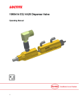
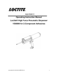
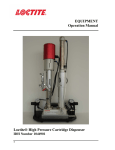
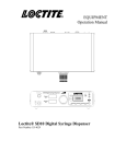
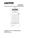
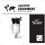
EQUIPMENT Operation Manual Loctite® 150Bar/3mm Dispense Valve IDH Number 1153502 1 Contents 1. PLEASE OBSERVE THE FOLLOWING ................................................................................................... 3 1.1 1.2 1.3 1.4 1.5 EMPHASIZED SECTIONS ............................................................................................................................. 3 ITEMS SUPPLIED ........................................................................................................................................ 3 FOR YOUR SAFETY ................................................................................................................................... 3 FEATURE ................................................................................................................................................... 3 USAGE ...................................................................................................................................................... 3 2. DESCRIPTION ............................................................................................................................................... 4 2.1 2.2 SPECIFICATION .......................................................................................................................................... 4 VALVE COMPONENTS AND DIMENSIONS ................................................................................................... 4 3. UNPACKING AND INSPECTION ............................................................................................................... 5 4. TYPICAL SYSTEM SETUP .......................................................................................................................... 5 5. SETUP AND OPERATION ........................................................................................................................... 6 5.1 5.2 CONNECTION ............................................................................................................................................. 6 OPERATION ............................................................................................................................................... 7 6. TROUBLESHOOTING .................................................................................................................................. 8 7. SPARE PARTS/ ACCESSORIES .................................................................................................................. 8 8. WARRANTY ................................................................................................................................................... 9 2 1. Please Observe the Following 1.1 Emphasized Sections WARNING! Refers to safety regulations and required measures that protect the operator or other persons from injury or danger to life. Caution! Emphasizes what must be done or avoided so that the unit or other property is not damaged. Notice: Gives recommendations for better handling of the unit during operation or adjustment, as well as for service activities. 1.2 Items Supplied 1 150Bar/3mm Dispense Valve 2 2 meters air line tubing 1 Fluid Outlet Tip Adapter (Attached to Valve) 1 Fluid Inlet Fitting (Attached to Valve) 2 Air Input Fitting (Attached to Valve) 1 Operation Manual 1.3 For Your Safety For safe and successful operation of the unit, read these instructions completely. If the instructions are not observed, the manufacturer can assume no responsibility. Observe general safety regulations for the handling of chemicals! Observe manufacturer’s instructions! Request a safety data sheet for the product used! When working with pressurized air, wear protective glasses! This valve operates under maximum air pressure input is 6 bars, do not exceed! This valve operates under maximum fluid pressure is 150 bars, do not exceed! While under warranty, the unit must be repaired by an authorized Loctite® brand service representative. 1.4 Features Maximum working fluid pressure: 150 bars (2175 psi) Maximum cylinder air pressure: 6 bars (85 psi) Bubble free, no-drip dispensing High resolution stroke adjustment Needle Shut-Off 1.5 Usage The Loctite® 150 Bar/ 3mm Dispense Valve is a double acting dispense valve that is used to dispense high viscosity silicone, MS polymer and urethane products. It is a stainless steel body, needle off dispense valve which can operate at fluid pressures up to 150 bars. 3 2. Description 2.1 Specification Pneumatic Supply Min. 4 Bars (min. 55 psi) Max. 6 Bars (max. 85 psi) Filtered 10μm, oil free, non-condensing If the required quality is not achieved, install a Loctite® filter regulator 97120 6.220” length x 1.181” width x 1.181” height (158 x 30 x 30 mm) 0.118” diameter (3 mm) ¼-19 BSPT Max. 2175 psi (150 bars) 0.683 kg Quality Size Free Flow Orifice Inlet Thread Fluid Pressure Weight 2.2 Valve Components and Dimension .984 [25.0] .433 [11.0] .787 [20.0] .827 1/4-19 BSPT [21.0] 2.362 2.441 .590 [60.0] [62.0] [15.0] 7.721 [196.1] Fluid Inlet Fitting "Port A" #1553588 Fluid Outlet Tip Adapter "Port B" #1119605 Valve Open Port Fitting "Port D" Kit #1119603 Valve Close Port Fitting "Port C" Kit #1119603 1.181 [30.0] Item Number: 1153502 Serial # .866 1.181 [22.0] [30.0] .866 Stroke Adjustment Nut 4 [22.0] 3. Unpacking and Inspection Carefully remove the system from its shipping carton, and inspect it for any signs of damage. Any damage should be reported immediately to the carrier. Refer to the list of parts supplied (page 1), and compare to the contents. Report any missing parts promptly to the Loctite® customer service department at 1-800-LOCTITE (562-8483) 4. Typical System Setup Plant air must be properly filtered and dry. If not, specify a 10-micron filter regulator (Order Locally) Paste Pump System Loctite® 150 bar/3mm Dispense Valve 1153502 Loctite® Controller 5 Loctite® High Viscosity 5. Setup and Operation 5.1 Connection Connect the 4 mm O.D. airline to the air fitting “port D” and the other end of airline will be connected to the normally opened port of solenoid valve. Connect the 4 mm O.D. airline to the air fitting “port C” and the other end of airline will be connected to the normally closed port of solenoid valve. Connect the fluid reservoir feed tube to the fluid inlet “port A” and tighten it well. Make sure the tube was cut at a right angled cut. Tube cutter is recommended 5.2 Operation With the Semi-Automatic Controller 97101 set up and connected to the valve, and the High Viscosity Paste Pump System connected as shown on page 5, load the High Viscosity Paste Pump System per High Viscosity Paste Pump System Operating Manual instructions. CAUTION: Always treat a pressurized reservoir with respect, and check air gauge to ensure pressure is at zero before opening. After filling, check to be certain the system is sealed. Before proceeding, check the following: 1. 2. 3. Be sure all the connections are tight. Set the valve control air pressure at a minimum of 60 psi (4 Bars). Actuate the valve long enough to fill the valve, start liquid flow and purge air from the dispensing tip. If a small tip is used, it may need to be removed from the valve during purging. Then fill the tip hub with fluid and install on the tip adapter so it is free of air. To open the valve: 1. Apply air pressure to OPEN air port (Port D) on the valve, and remove pressure from the CLOSE (Port C) air port on the valve. 2. Maintain air pressure on the OPEN (Port D) air port to keep the valve open. To close the valve: 1. Apply air pressure to CLOSE air port (Port C) on the valve, and remove pressure from the OPEN (Port D) air port on the valve. 2. Maintain air pressure on the CLOSE (Port C) air port to keep the valve open. 6 5. Setup And Operation 5.3 Shutdown 1. To prevent the nozzle from coming in contact with air, put an end-cap on the nozzle or keep the nozzle in the grease. 5.4 Returning to Operation 1. Remove the end-cap from the nozzle. 2. If needed, purge the product feedline and dispensing valve Returning to Operation After Longer Periods of Non-use. 1. Remove the Luer-Lock tip cap 2. Purge the product feedline and dispensing valve 6. Troubleshooting Problem No product or too little product Possible Cause Product feedline not correctly connected Pneumatic hose not correctly connected Controller incorrectly adjusted Valve operating pressure is too low The dispensing tip is clogged Curing in the product feedline and/or in the dispensing valve Air bubble in product Air in the dispensing valve/product feedline Inconsistent deposits The air pressure controlling the valve and/or Pump System is fluctuating The open time of the valve timer must be constant 7 Correction Correctly connect the product feedline Correctly connect the pneumatic hose Check the controller (see operating instructions for the controller) Increase air pressure to 60psi (4 bar) minimum Replace the tip Replace the product feedline and clean dispensing valve head Purge the product feedline, dispensing valve and dispensing tip Check to be make sure the air pressures are constant Check to be sure the valve controller is providing a consistent output 7. Accessories and Spare Parts Number 1 2 3 4 5 6 7 8 9 10 11 8 Loctite® Item Number 1119605 1553588 1153500 1153498 Call 860-571-5174 For Quote 1153492 Description Fluid Outlet Tip Adapter Fluid Inlet Fitting Air Input Fitting Kit Actuator Seal Kit – O-Ring, Viton Actuator Seal Kit – O-Ring, Buna-N Actuator Seal Kit – O-Ring, Silicone Actuator Seal Kit – O-Ring, Silicone Needle, Tool Steel Shaft Seal Kit – Packing for 8, PTFE Outlet Seal Kit – Adapter Packing, PTFE Outlet Seal Kit – Needle Seat, PTFE 8. Warranty EQUIPMENT WARRANTY For Loctite® 150Bar/3mm Dispense Valve Henkel expressly warrants that all products referred to in this Instruction Manual Dispense Valve 1153502 (hereafter called “Products”) shall be free from defects in materials and workmanship. Liability for Henkel shall be limited, at its option, to replacing those Products which are shown to be defective either in materials or workmanship or to credit to the purchaser the amount of the purchase price thereof (plus freight and insurance charges paid therefore by the user). The purchaser’s sole and exclusive remedy for breach of warranty shall be such replacement or credit. A claim of defect in materials or workmanship in any Products shall be allowed only when it is submitted to Henkel in writing within one month after discovery of the defect or after the time the defect should reasonably have been discovered and in any event, within twelve months after the delivery of the Products to the purchaser. No such claim shall be allowed in respect of Products which have been neglected or improperly stored, transported, handled, installed, connected, operated, used or maintained or in the event of unauthorized modification of the Products including, where products, parts or attachments for use in connection with the Products are available from Henkel, the use of products, parts or attachments which are not manufactured by Henkel. No Products shall be returned to Henkel for any reason without prior written approval from Henkel. Products shall be returned freight prepaid, in accordance with instructions from Henkel. NO WARRANTY IS EXTENDED TO ANY EQUIPMENT WHICH HAS BEEN ALTERED, MISUSED, NEGLECTED, OR DAMAGED BY ACCIDENT, OR IF THE SYSTEM USED TO DISPENSE ANY LIQUID MATERIAL OTHER THAN LOCTITE® PRODUCTS. EXCEPT FOR THE EXPRESS WARRANTY CONTAINED IN THIS SECTION, HENKEL MAKES NO WARRANTY OF ANY KIND WHATSOEVER, EXPRESS OR IMPLIED, WITH RESPECT TO THE PRODUCTS. ALL WARRANTIES OF MERCHANTABILITY, FITNESS FOR A PARTICULAR PURPOSE, AND OTHER WARRANTIES OF WHATEVER KIND (INCLUDING AGAINST PATENT OR TRADEMARK INFRINGEMENT) ARE HEREBY DISCLAIMED BY HENKEL AND WAIVED BY THE PURCHASER. THIS SECTION SETS FORTH EXCLUSIVELY ALL OF LIABILITY FOR HENKEL TO THE PURCHASER IN CONTRACT, IN TORT OR OTHERWISE IN THE EVENT OF DEFECTIVE PRODUCTS. WITHOUT LIMITATION OF THE FOREGOING, TO THE FULLEST EXTENT POSSIBLE UNDER APPLICABLE LAWS, HENKEL EXPRESSLY DISCLAIMS ANY LIABILITY WHATSOEVER FOR ANY DAMAGES INCURRED DIRECTLY OR INDIRECTLY IN CONNECTION WITH THE SALE OR USE OF, OR OTHERWISE IN CONNECTION WITH, THE PRODUCTS, INCLUDING, WITHOUT LIMITATION, LOSS OF PROFITS AND SPECIAL, INDIRECT OR CONSEQUENTIAL DAMAGES, WHETHER CAUSED BY NEGLIGENCE FROM HENKEL OR OTHERWISE. Henkel Corporation One Henkel Way Rocky Hill, CT 06067-3910 USA Henkel Canada Corporation 2225 Meadowpine Boulevard Mississauga, Ontario L5N 7P2 CANADA Henkel Corporation Automotive/Metals H.Q. 32100 Stephenson Hwy, Madison Heights, MI 48071 USA Henkel Capital, S.A. de C.V. Calzada de la Viga s/n Fracc. Los Laureles Loc. Tulpetlac, C.P. 55090 Ecatepac de Morelos, MEXICO Henkel Singapore Pte Ltd Blk 5002 Ang Mo Kio Ave 5 #03-12 TECHplace 2, 569871 SINGAPORE Henkel (China) Company Ltd. No. 928 Zhang Heng Road, Zhangjiang, Hi-Tech Park, Pudong, Shanghai, China 201203 Henkel Loctite Korea 8F, Mapo Tower, 418, Mapo-dong, Mapo-gu, Seoul, 121-734, KOREA Henkel Japan Ltd. 27-7 Shin Isogo-cho, Isogo-ku Yokohama, 235-0017 JAPAN www.equipment.loctite.com Loctite is a trademark of Henkel Corporation, U.S.A. © Copyright 2006. Henkel Corporation Teflon is a registered trademark of E.I. DuPont de Nemours Co., Inc. All rights reserved. Data in this operation manual is subject to change without notice. Manual P/N: 8901685 Rev C Date: 09/2014 9