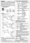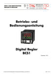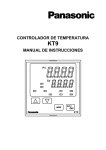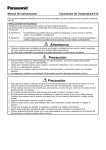
1
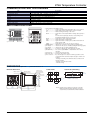
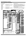
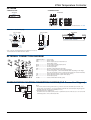
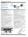
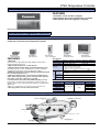
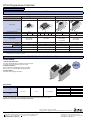
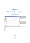
KT4H Temperature Controller
KT4H Temperature
Controller
Compact Body with
Numerous Features
2) 11-segment LCD improves ability to
distinguish alphanumeric.
3) Largest letter height of PV value in its
class for easy readability even from a
distance.
2. Space savings (Depth: 56mm)
Control panel installation length has been
shortened to the utmost.
3. Ability to use any sensor (input) is
inherited from KT Series
The KT4H comes standard with ability to
use any sensor (input): thermocouple
(10 types), RTD (2 types), DC current
(2 types), and DC voltage (4 types)
4. Simple operation enables highly
accurate temperature control
The operation mode uses “PID control”
which allows a stable temperature to be
maintained. Capable of high accuracy
with an input span of ±0.2% and a highspeed sampling period of 250 ms.
5. Improved communication functions
1) MEWTOCOL communications protocol
is built in. Up to 31 temperature
controllers can be connected and data
can be collected using a DLU (Web
RoHS Directive compatibility information
http://www.mew.co.jp/ac/e/environment/
FEATURES
1. Better visibility
1) The KT4H uses our time-proven
display system (negative type LCD + LED
backlight) that is used in our timers and
counters.
Datalogger Unit) or similar.
2) Using the external tool port, all settings
can be loaded and settings can be made.
6. Easier operation
1) The switch layout has been changed
and mode changes easier using the front
keys.
2) Improved switch construction provides
a much more positive clicking action.
7. Protective construction
Despite its compact size, protective
structure conforms to IP66 (front panel
only, when using rubber packing).
8. Improved control functions (option)
1) Capable of 4-point temperature
selection by external input.
2) Control output can be turned ON and
OFF externally.
3) 3-phase heater burn-out detection
function
4) Non-contact voltage output in heating/
cooling control output available.
9. Complies with international
standards.
UL and C-UL compliance. CE marking
conformity.
PRODUCT TYPES
KT4H Series
Base
model
AKT4H
Power
supply
Sensor
input
Control
output
Alarm
output
Heating/
Heater Communications
cooling control burnout alarm function
1
2
1
1
2
3
0
1
2
0
0
1
2
0
0
0
1 or 2
0
3
1 or 2
0
4
1 or 2
0
5
1 or 2
0
6
Blank
1
2
Description
100 to 240V AC
24V AC/DC
Multi-input (Thermocouple, RTD, DC Voltage and DC Current)
Relay contact
Non-contact voltage (for SSR drive)
DC current
Heater burn-out alarm not possible.
1 point (1a)
2 points (1a + 1a)
Heating/cooling control output not possible.
Not available
Relay contact
Heater burn-out alarm not possible.
Non-contact voltage (for SSR drive) Heater burn-out alarm not possible.
Not available
Single phase 20A (Heater burn-out alarm not supported when control output
is DC output type/not supported when heating and cooling control is selected)
Single phase 50A (Heater burn-out alarm not supported when control output
is DC output type/not supported when heating and cooling control is selected)
Three phase 20A (Heater burn-out alarm not supported when control output
is DC output type/not supported when heating and cooling control is selected)
Three phase 50A (Heater burn-out alarm not supported when control output
is DC output type/not supported when heating and cooling control is selected)
Not available
Serial communication RS-485
Contact input
Notes: 1. CT1 or CT2 for current transformer is provided as an accessory when heater burn-out alarm function is added.
2. Under some conditions, option functions (shaded items) may not be available; please check the “Descriptions” of the above table for non-functioning circumstances.
● Part No.
Example: Part No. when the optional functions (Heating/Cooling control + communication function) are added on to the basic model are as follows;
Part No.: AKT4H1111101
KT4H Temperature Controller
ARCT1B291E ’07.10
http://www.mew.co.jp/ac/e/
New
1
Matsushita Electric Works, Ltd.
KT4H Temperature Controller
● Options
● Setting software
Product name
Shunt resistor (for Current input)
Terminal cover
Tool cable
Part No.
AKT4810
AKT4H801
AKT4H820
Product name
Description
KT Monitor
Editing of all types of data, File saving
Monitoring of readings, Saving of log files
Remark
Available for download at no charge from
company website.
http://www.mew.co.jp/ac/e
Note: Please download user manual from the company website.
RATING & SPECIFICATIONS
Item
Specifications
Size (W × H × D)
Supply voltage (Must be specified)
Frequency
Power consumption
Input type
Rated graduation
Rating
K
J
R
S
Thermocouple B
E
T
N
PL-II
C (W/Re5-26)
Pt100
RTD
JPt100
DC
Current 4 to 20mA DC
0 to 20mA DC
0 to 1V DC
0 to 10V DC
Voltage
1 to 5V DC
0 to 5V DC
Multi-input
–2000 to 10000
• Scaling and change to the decimal point position are possible for DC current and DC voltage input.
• DC current input is supported with an externally mounted 50Ω shunt resistor (sold separately).
K, J, R, S, B, E, T, N, PL-II, C (W/Re5-26)
External resistor: Max. 100Ω (max. 40Ω external resistor for B input)
Thermocouple
RTD
Pt100, JPt100Ω 3-conductor system (Allowable input conductor resistance for each conductor: max. 10Ω)
DC current
DC voltage
0 to 20mA DC
4 to 20mA DC
0 to 1V DC
0 to 5V DC
1 to 5V DC
0 to 10V DC
Control
output
Relay contact
(Contact material: Ag alloy)
(Must be specified)
Non-contact voltage
DC current
Alarm output 1 (EVT1)
Relay contact (Contact material: Ag alloy)
Alarm output 2 (EVT2)
Control mode
Target temperature setting
Accuracy
48 × 48 × 62mm
100 to 240V AC
24V AC/DC
50/60Hz
Approx. 8VA
Input range
–200 to 1370°C (–320 to 2500°F)
–200.0 to 400.0°C (–320.0 to 750.0°F)
–200 to 1000°C (–320 to 1800°F)
0 to 1760°C (0 to 3200°F)
0 to 1760°C (0 to 3200°F)
0 to 1820°C (0 to 3300°F)
–200 to 800°C (–320 to 1500°F)
–200.0 to 400.0°C (–320.0 to 750.0°F)
–200 to 1300°C (–320 to 2300°F)
0 to 1390°C (0 to 2500°F)
0 to 2315°C (0 to 4200°F)
–200 to 850°C (–320 to 1500°F)
–200.0 to 850.0°C (–320.0 to 1500.0°F)
–200 to 500°C (–320 to 900°F)
–200.0 to 500.0°C (–320.0 to 900.0°F)
Thermocouple
Input impedance: 50Ω (Connect 50Ω shunt resistor between input terminals.)
Allowable input current: max. 50 mA (when 50Ω shunt resistor is used)
Input impedance: min. 1 MΩ, Allowable input voltage: max 5 V, Allowable signal source resistance: max. 2 kΩ
Input impedance: min. 100 kΩ, Allowable input voltage: max 15 V, Allowable signal source resistance: max. 100kΩ
1a: 3A 250V AC (Resistive load), 1A 250V AC (Inductive load cosφ=0.4), Electric life: 100,000 times
12V DC±15%, Max. load current: 40mA (Short-circuit protected)
4 to 20mA DC Load resistance: Max. 550Ω
Relay contact 1a: 3A 250VAC (Resistive load)
Electric life: 100,000 times
Same as Alarm output 1
Actions mentioned below can be selected by key operation. [Default PID] PID (with auto-tuning function), PI, PD (with manual reset function), P (with manual reset function), ON/OFF action
Primary setting/secondary setting/third setting/fourth setting (switched by external terminal)
Within ±0.2% of each input span ±1 digit or within ±2°C (4°F) whichever is greater
However, R and S input; Within ±6°C (12°F) in the range of 0 to 200°C (32 to 400°F)
B input 0 to 300°C (32 to 600°F): Accuracy is not guaranteed. K, J, T, E, and N input less than 0°C (32°F): Within ±0.4% of input span ±1 digit
Within ±0.1% of each input span ±1 digit or ±1°C (2°F) whichever is greater
Within ±0.2% of each input span ±1 digit
RTD
DC current and DC voltage
Sampling period
250ms
Hysteresis (ON/OFF)
Thermocouple & RTD: 0.1 to 100.0°C (32.18 to 212°F)
DC current and DC voltage: 1 to 1000 (The decimal point place follows the selection)
Proportional band
0 to 1000°C (32 to 1832°F)
The decimal point input: 0.0 to 1000°C (32 to 1832°F)
DC current and DC voltage: 0.0 to 100.0%
Integral time
Derivative time
Proportional cycle
Allowable voltage fluctuation
Insulated resistance
Breakdown voltage
Malfunction vibration
Breakdown vibration
Malfunction shock
Breakdown shock
Ambient temperature
Ambient humidity
Mass
Waterproof
Options
Display character height
Relay contact (Contact
Heating/ Output
Cooling (Must be material: Ag alloy)
control specified) Non-contact voltage
Heater burn-out alarm output
(Relay contact material: Ag alloy)
Tool port
Accessories
2
Mounting frame
Rubber gasket
0 to 1000 seconds
0 to 300 seconds
1 to 120 seconds
When 100 to 240V AC; 85 to 264V AC When 24V AC/DC; 20 to 28V AC/DC
500V DC 10MΩ or greater
1.5kV AC for 1 min
between input terminal and power terminal,
& between output terminal and power terminal
10 to 55 Hz (1 cycle/min.) single amplitude 0.35 mm (10 minutes on 3 axes)
10 to 55 Hz (1 cycle/min.) single amplitude 0.75 mm (1 hour on 3 axes)
X, Y & Z each direction for 5 times 98m/s2
Same as above, but 294m/s2
0 to 50°C
35 to 85%RH (No condensation)
Approx. 120g
IP66 (applicable only to the front panel subject to rubber gasket employed)
PV: 12mm
SV: 6mm
Control capacity 1a: 3A 250V AC (Resistive load), Electric life: 100,000 times
12V DC±15% Max. 40mA (Short-circuit protected)
Specify either single-phase 20 A, single-phase 50 A, 3-phase 20 A, or 3-phase 50 A for rated heater current.
Setting accuracy: within ±5% of rated heater current
Relay contact 1a: 3A 250V AC (Resistive load), Electric life: 100,000 times
Communication interface C-MOS level
Cannot be used at the same time as serial communication (option).
*This port can only be used with the tool cable (AKT4H820).
Comes with KT4H.
KT4H Temperature Controller
COMMUNICATION FUNCTION OVERVIEW
Item
Communication type
Communication speed
Synchronization type
Protocol
Coding
Interface
No. of nodes
Maximum cable length
Specifications
Half-duplex
Select 2400, 4800, 9600, or 19200 bps using key operation.
Asynchronous
Modbus RTU, Modbus ASCII, MEWTOCOL (Slave)
Binary/ASCII
EIA RS485 compliant
31
1,000 m (cable resistance must be within 50Ω)
PARTS AND FUNCTIONS
1
1 Action indicators (backlight: orange)
°F °C ..................... Lights respectively when temperature unit °F/°C is selected.
T/R ........................ Lights during Serial communication (option) TX output.
AT ......................... Flashes during auto-tuning or auto-reset
OUT1 .................... Lights when control output is ON or Heating output (option) is
ON.
For DC current output type, it flashes corresponding to the
manipulated variable in 0.25 second cycles.
OUT2 .................... Lights when Cooling output (option) is ON.
EVT1 ..................... Lights when Alarm 1 output is ON.
EVT2 ..................... Lights when Alarm 2 output (option) is ON or Heater burnout
alarm (option) is ON.
LOCK .................... Lights when Lock 1, Lock 2 or Lock 3 is selected.
2 MEMO display ....... Indicates the set value memory number (backlight: green).
3 PV display ............. Indicates the PV (process variable) (backlight: red/orange/green).
4 SV display ............. Indicates the SV (set value) (backlight: green).
5 Mode key ............... Selects the setting mode, and registers the set value.
6 OUT/OFF key ........ The control output ON/OFF or Auto/Manual control can be
switched.
7 Increase key .......... Increases the numeric value.
8 Decrease key ........ Decreases the numeric value.
9 Tool connector ....... By connecting the tool cable, the following operations can be
conducted from the external computer using the exclusive tool
software.
- Reading and setting of SV, PID and various set values from
external computer
- Reading of PV and action status
- Function change
3
4
2
9
5
7
6
8
(Bottom side)
DIMENSIONS (Unit: mm inch) General tolerance: ±1 ±.039
External dimensions
Rubber gasket
1.5
.059
Mounting frame
Terminal cover
(Sold separately)
Panel cutout
Lateral close mounting
+0.5
45 0
+.020
1.772 0
M3 screw
75
2.953
n × 48 − 3
+0.5
44.5
59.2
1.752
2.331
47.5
1.870
45 0
+.020
1.772 0
45
6
.236
56.0
2.205
61.0
2.402
+0.5
0
+.020
0
n: Number of units mounted
+0.5
0
1.772
48
1.890
n × 1.890 − .118
+.020
0
Notes: If lateral close mounting is used for the controller,
IP66 specification (Dust-proof/Drip-proof) may be
compromised, and all warranties will be invalidated.
3
KT4H Temperature Controller
BASIC OPERATING PROCEDURES
1. Setup Procedures
The setup procedures of this controller is shown below. Refer to each
item for details.
1. Specification setting:
Settings for input type, alarm actions, etc., are set using the
specification setting mode.
(If the users’ specification is the same as the default value,
specification setting is not necessary for the controller.)
2. Main setting mode:
Set Step SV during main setting mode.
3. Sub setting mode:
Set PID values, A1 setting, etc.
(If the users’ PID values are the same as the default value, it
is not necessary to set them.)
Set the Lock function, Communication conditions (Option:
serial communication), etc.
(If the users’ specification is the same as the default value, it
is not necessary to set them.)
4. Auxiliary function setting mode:
2. Specification setting
Before using the unit, it is necessary to adjust settings, such as input
type, alarm actions, control actions, and other items, to match the
conditions of use. This is known as specification setting.
Factory settings at time of shipment are, input: K -200° to 1,370°C; and
Alarm 1: no operation, comes into operation reverse (heating). If the
factory settings are acceptable, the specification settings will be
appropriate when the device is installed into the equipment and the
specification setting procedure will not be required
3. Basic setting operations
For setting-mode navigation, refer to the particular setting mode.
After navigation using the
and
keys, setting (selection) of each
setting (selection) item is done by registration using the
key.
Power on
Running
Power on
Control output off function or manual control function
When control output is OFF PV/SV display mode (automatic control)
(approx. 1 sec.)
After the power is turned on, for about 3 seconds the PV display
shows the input type, and the SV display shows the upper value of
the input range (thermocouple and resistance temperature detector
input) or scaling upper limit (DC voltage, DC input current).
(approx. 3 sec.)
Output Operation Volume (MV) indication
When control is automatic/manual
[Main setting mode]
SV setting
[Sub setting mode]
Auto-tuning/
Auto-reset selection
(approx. 3 sec.)
(approx. 3 sec.)
[Auxiliary function setting mode]
[Specification setting mode]
Setting value lock
Input type selection
selection
Alarm 2 Operation
energized/non-energized
selection
SV2 setting
OUT1 Proportional
band setting
Sensor calibration
setting
Scaling high limit
setting
Alarm 1 Operation
gap setting
SV3 setting
OUT2 Proportional
band setting
Communication
protocol selection
Scaling low limit
setting
Alarm 2 Operation
gap setting
SV4 setting
Integral time setting
Device number
setting
Decimal point
location selection
Alarm 1 Operation
delay timer setting
Derivative time setting
Communication
speed selection
PV Filter time
Constant Setting
Alarm 2 Operation
delay timer setting
ARW setting
Data bit/Parity
selection
OUT1 high limit
setting
SV elevation rate set
OUT1 Proportional
frequency setting
Stop bit selection
OUT1 low limit
setting
SV decline rate set
OUT2 Proportional
frequency setting
Communication
response time
selection
OUT1 ON/OFF
operation gap setting
Normal/Reverse
control operation
selection
Alarm 1 setting
OUT2 Operation
mode selection
AT bias setting
Alarm 2 setting
OUT2 high limit
setting
Contact input
function selection
Heater cutoff
alarm setting
OUT2 low limit
setting
Output status on
input fault selection
Heater cutoff
alarm2 setting
Overlap/Dead
band setting
OUT/OFF key
function selection
OUT2 ON/OFF
operation gap setting
Backlight illumination
segment selection
Alarm 1 operation
selection
PV display color
switch selection
Alarm 2 operation
selection
PV display color
switch range setting
Alarm 1 Operation
energized/non-energized
selection
Backlight illumination
time setting
[Key operation]
While pressing
key, press the
key.
(approx. 3 sec.) While pressing
key, press the
key for about 3 sec.
(approx. 3 sec.) While pressing
key, press the
key for about 3 sec.
When the
key is pressed, navigation to the arrowed item is indicated.
Setting items in dotted line boxes only appear when options are added.
Numbers in square brackets [ ], correspond to numbered setting items in this document.
Note: Please refer to the user manual for detailed operating procedures.
4
KT4H Temperature Controller
OPTIONS
1. Shunt resistor
2. Terminal cover
AKT4810
AKT4H801
74 ±6
2.913 ±.236
44.5
1.752
47.5
1.870
>PC<
46.5
1.831
3. Current transformer (CT)
4. Tool cable
CT1 (for 20A)
5.8 dia.
.228 dia.
l 15 k
.591 0.5
.020
7.5
.295
CT2 (for 50A)
l
2.8
.110
K
30 k
1.181
AKT4H820
n2.5 Plug 3-Pole type
200±20
7.784±.787
21
.827
40
1.575
3
.118
30
1.181
2-3.5 dia.
2-.138 dia.
20
.787
USB Plug
35
1.378
100
3.937
L
25
.984
10.5
.413
General tolerance: ±1 ±.039
17
.669
50
1.969
2000±40
78.74±1.575
40
1.575
10
.394
40
1.575
30
1.181
12 dia. 15
.472 dia. .591
2-M3
2-M.118
*CT1 or CT2 for current transformer is provided as an accessory
when heater burn-out alarm function is added.
EXTERNAL CONNECTION DIAGRAM
POWER SUPPLY ....... Power supply
EVT1 .......................... Alarm 1 output
EVT2 .......................... Alarm 2 output (option) or heater burn-out
Alarm output (option)
OUT1 ......................... Control output or heating output (option)
OUT2 ......................... Cooling output (option)
TC .............................. Thermocouple input
RTD ........................... Resistance temperature detection input
DC .............................. Direct current input (DCA) or DC voltage input (DCV)
(For DC voltage input, + side terminal number differs depending on the voltage.
Also, DC current input, connect s shunt resistor between No. 10 and 12 terminal.)
CT1 ............................ Current transformer input 1 (option: Single, three phase)
CT2 ............................ Current transformer input 2 (option: Three-phase)
DI ............................... Contact input (option)
RS-485 ....................... Serial communication RS-485 (option)
COMMUNICATION FUNCTION CONNECTION DIAGRAM (PLC Connection Diagram)
PLC
(−)
RS-485
(+)
KT4H
16 YA (−)
17 YB (+)
18 COM
Shielded cable
KT4H
16 YA (−)
Notes:
1. To prevent current flow along shield sections, ground one end of the shield line. (If both ends of the
shield section are grounded, a closed circuit with the earth will form and electricity flowing through the
shield line will cause increased susceptibility to noise.)
2. Terminating Resistors (Terminators)
The KT4H series has a built-in pull-up resistor or pull-down resistor. For this reason, do not connect the
terminating resistor on the communication line.
17 YB (+)
18 COM
5
KT4H Temperature Controller
INSTALLATION
Please install vertically in order to satisfy
the IP66 specification for dust and splash
proofing.
The possible control panel plate
thickness for installation is between 1 to 5
mm.
1) Insert the unit from the front of the
control panel.
2) Push the installation frame fully into
contact with the panel and tighten the
screws (screw torque from 0.05 N⋅m to
0.06N⋅m).
Rubber gasket
NOTICE ON OPERATION
1. Notice on site selection
This instrument is intended to be used in the following
environment (IEC61010-1)
Over voltage category II, Pollution degree 2
Mount the controller in a place with:
1) A minimum of dust, and an absence of corrosive gases
2) No flammable, explosive gases
3) Few mechanical vibrations or shocks
4) No exposure to direct sunlight, an ambient temperature of 0 to
50°C (32 to 122°F) that does not change rapidly
(When installing inside a panel, make particular allowance for
heat dissipation. Avoid installation in situations such as above
equipment that generates heat.)
5) Locations in which temperature rapidly changes may cause
condensation.
6) Locations or atmospheres in which gasoline, thinners,
alcohol, or other organic solvents are present, or in which
ammonia, sodium hydroxide, or other strong alkaline substances
may adhere.
7) Locations susceptible to direct impact or the transmission of
vibrations, or where splashing with water is possible.
8) In the proximity of equipment in which large switching surges
occur or near high-voltage cables, high-voltage equipment,
power lines, power equipment, ham radio transmitters, or
equipment containing these or similar devices.
9) An ambient non-condensing humidity of 35 to 85%RH
10) No large capacity electromagnetic switches or cables
through which large current is flowing
11) No water, oil or chemicals or where the vapors of these
substances can come into direct contact with the controller
2. Notice on the wiring
1) The terminal block of KT4H series is designed to be wired
from the left side
The lead wire must be inserted from the left side of the terminal,
and fastened by the terminal screw. Use a solder-less terminal
with insulation sleeve that fits to the M3 screw.
Wire-pressed
terminal
Fork type
Round type
Company name
NICHIFU Co., Ltd.
1.25Y-3
J.S.T. Mfg. Co., Ltd.
NICHIFU Co., Ltd.
J.S.T. Mfg. Co., Ltd.
VD1.25-B3A
1.25-3
V1.25-3
3.2 mm dia.
.126 inch dia.
5.8 mm
max.
.228 inch
max.
Part number
Fastening
torque
0.6 N⋅m,
Max.
1.0 N⋅m.
3.2 mm dia.
.126 inch dia.
CT input terminal
Power supply
CT
5.8 mm
max.
.228 inch
max.
2) Recommended terminal fastening torque is approximately:
0.6N⋅m to 1.0N⋅m.
3) Use a thermocouple and compensating lead wire according to
the input specification of the controller.
6
4) Use a 3-wire system of RTD according to the input
specification of the controller.
5) This controller has no built-in power switch, circuit breaker or
fuse. Therefore, it is necessary to install them in the circuit near
the external controller.
(Recommended fuse: Time-lag fuse, rated voltage 250V AC,
rated current 2A)
6) In the case of 24V AC/DC power supply, do not confuse the
polarity when it is DC.
7) With the relay contact output type, use an auxiliary
electromagnetic switch externally according to the capacity of
the load to protect the built-in relay contact.
8) When wiring, keep input wire (thermocouple, RTD, etc.) away
from AC source and load wire to avoid external interference.
9) Turn the power supply to the instrument off before wiring or
checking. Working or touching the terminal with the power
switched on may result in Electric Shock which could cause
severe injury or death.
10) Do not drop wire chips into the holes of vent when wiring,
because they could cause fire, malfunction or trouble with the
device.
11) To prevent the unit from harmful effects of unexpected high
level noise, it is recommended that a surge absorber be installed
between the electromagnetic switch coils.
3. NOTICE ON THE MOUNTING
Do not use excessive force while screwing in the mounting frame
of KT4H series. Recommended torque is approximately 0.05 to
0.06 N⋅m.
4. OPTIONAL HEATER BURN-OUT ALARM OUTPUT
1) This alarm is not available for detecting current under phase
control.
2) Use the current transformer (CT) provided, and pass one lead
wire of the heater circuit into the hole of CT.
3) When wiring, keep CT wire away from AC source and load
wire to avoid external interference.
4) In three phase installations, ensure that R, S, and T are each
connected to a 2-line CT that connects with CT1 ((13)–(14)) and
CT2 ((14)–(15)) terminals.
Heater
KT4H Temperature Controller
KT Monitor
Available for download free of charge. Use it to acquire data from the KT4H temperature controller.
FEATURES
1. Parameters can be set from a computer.
2. Measurement data can be monitored from a computer.
3. Measurement data can be logged to a computer.
Download from http://www.mew.co.jp/ac/e
Recommended Temperature Controllers
KT Series Temperature Controllers
Economically priced models that provide high accuracy with easy operation. The newly added KT2 series enables pattern
control with a small form factor temperature controller.
KT2 Series
KT4 Series
KT7 Series
KT8 Series
KT9 Series
(48×24×98.5mm)
(48×48×95mm)
(22.5×75×100mm)
Specifications
(48×96×98.5mm)
(96×96×98.5mm)
1. Multi-input
Versatile thermocouple, RTD, DC voltage and DC current input for
temperature detecting sensors
2. Meets market demands for costeffectiveness
3. Simple operation enables highly accurate temperature control
All required operations can be enabled by the front keys and highly
accurate PID control mode ensures an input span of ±0.2%.
4. DIN Rail mounting types are aligned taking global market demand
into consideration (KT7 series)
5. With three additional types of option function (heater burnout
alarm output, heating/cooling control, and spare alarm output) for
each series, a selection of 232 types is possible
6. Communication specification uses RS485 (Modbus protocol)
It is possible to connect up to 31 temperature controllers, which can
facilitate central control (temperature data acquisition and setting value
adjustment).
Type
KT2 Series KT7 Series KT4 Series KT8 Series KT9 Series
Supply voltage
100 to 240 V AC, 24 V AC/DC (Must be specified)
Power consumption Approx. 5 VA Approx. 6 VA
Approx. 8 VA
Thermocouple: K, J, R, S, B, E, T, N, PL-11, C (W/Re5-26)
RTD: PL100, JPt100 3-conductor system
Multi-input
DC current: 0 to 20mA DC, 4 to 20mA DC
DC voltage: 0 to 1 V DC, 0 to 5 V DC, 1 to 5 V DC, 0 to 10 V DC
1a
1a
1a1b
Relay contact
3 A 250 V AC (Resistive load), 1 A 250 V AC (Inductive load cos φ =0.4),
100, 000 times
Non-contact DC
12 +20 V DC
voltage
DC current
4 to 20 mA DC
Control output
FEATURES
Product numbers
Types
KT2 Series
KT7 Series
KT4 Series
KT8 Series
KT9 Series
*Modbus is a communication protocol developed for PLCs by Modicon Inc.
7. Nine step pattern control possible. (KT2 series)
Supply voltage
Control output
100 to 240 V AC
Relay contact
output
Part No.
AKT2111200
AKT7111100
AKT4111100
AKT8111100
AKT9111100
Applications
Contributing to space savings of various heater control systems
Injection molding machine
Temperature controlled bath
<Temperature Control System Configuration>
Sensor
Printing machine
Heater
Controller
KT4H Temperature Controller
LCD curing oven
Kitchen appliance
7
KT4H Temperature Controller
Recommended SSR
Heater Control SSR Lineup
Wide range of selections for different applications
Type
SSR Stand Alone
AQ-J*1
Series
Slim Heat Sink Combined Type
AQ-N*1
AQ-J
New
30
1.181
max.
Dimensions
27
1.063
max.
38
1.496
28
1.102
45
1.772
58
2.283
Output arrangement
1a
10A
15A
15A
100
3.937
28
1.102
1a
10A
25A
113
4.449
max.
100
3.937
28
1.102
mm inch
Load current
New
113
4.449
max.
1a × 2
1a
20A
25A
40A
10A
20A
10A
15A
Load voltage
75 to 264V AC
75 to 250V AC
75 to 264V AC
75 to 264V AC
Input voltage
4 to 6V DC
10 to 18V DC
18 to 28V DC
4 to 32V DC
4 to 6V DC
10 to 18V DC
18 to 28V DC
4 to 6V DC
10 to 18V DC
18 to 28V DC
Operational method
Zero-cross (Turn ON and Turn OFF)*2
Zero-cross (Turn ON and Turn OFF)*2
Zero-cross (Turn ON and Turn OFF)*2
Screw
DIN rail
—
—
Varistor
LED indication
—
—
—
Terminal cover
—
—
—
Mounting
Notes: *1. A slim heat sink is available as an optional component.
*2. Random types are available upon request.
AQ-J SSR Slim Heat Sink Combined Type
FEATURES
1. 28mm-wide Slim Profile
Two ultra-small SSR units are built into a slim heat sink!
Uses 36% less space than the previous model
2. Simple Installation
Both screw mount and DIN rail mount are possible.
Easy connection of input/output with tab terminals
3. Built-in Varistor
Excellent external surge absorption
NEW
Part number
Output configuration
Type
Load current
Load voltage
Zero-cross
10 A
75 V to 264 V
1a
1ax2
Input voltage
4 to 6 V DC
10 to 18 V DC
18 to 28 V DC
4 to 6 V DC
10 to 18 V DC
18 to 28 V DC
Part No.
AQJ112VY
AQJ119VY
AQJ116VY
AQJ112VW
AQJ119VW
AQJ116VW
Check our website for more detailed product information about solid state relays.
http://www.mew.co.jp/ac/e/control/relay/solid-state/
These materials are printed on ECF pulp.
These materials are printed with earth-friendly vegetable-based (soybean oil) ink.
8
Matsushita
Electric Works, Ltd. Automation Controls Business Unit
Head Office: 1048, Kadoma, Kadoma-shi, Osaka 571-8686, Japan
Telephone: +81-6-6908-1050
Facsimile: +81-6-6908-5781
http://www.mew.co.jp/ac/e/
COPYRIGHT © 2007 All Rights Reserved
Specifications are subject to change without notice.
ARCT1B291E 200710-1YT
3. Communication parameter setting
Communication Installation Instructions
KT4H/B Temperature Controller
No. KT4HCE4 2009.11
These instructions are for communication functions. For detailed operating
instructions, please refer to User’s Manual for the KT4H/B.
Serial communication and Tool port communication cannot be used together.
When performing Serial communication, remove the tool cable (AKT4H820) from
the USB port of the PC and tool connector of the KT4H/B.
When performing Tool port communication, it is not required to remove the Serial
communication cables. However, do not send a command from the master side.
Set each communication parameter following the procedures below.
Proceed to Auxiliary function setting mode.
(1)
Press
key while pressing
key in
the PV/SV display mode. The unit proceeds
to Auxiliary function setting mode.
+
Auxiliary function setting mode
(2)
Press
key twice.
The unit proceeds to Communication protocol
selection.
(Twice)
Communication protocol selection
(3)
Select the communication protocol.
: Modbus ASCII mode (Default)
: Modbus RTU mode
: MEWTOCOL (Slave)
(4)
Instrument number setting
Set the instrument number of the controller
individually when communicating by connecting
plural instruments.
1 to 99 (Default: 1)
(5)
Communication speed selection
Set the communication speed equal to that of
the host computer.
: 2400bps
: 4800bps
: 9600bps (Default)
: 19200bps
(6)
Data bit/Parity selection
Select the data bit and parity.
: 8 bits/No parity
: 7 bits/No parity
: 8 bits/Even
: 7 bits/Even (Default)
: 8 bits/Odd
: 7 bits/Odd
(7)
Stop bit selection
Select the stop bit.
: 1 (Default)
:2
(8)
Communication response time setting
Set the minimum response time.
5 to 99 (Default: 5ms)
[17]
[19]
5. System configuration
Communication converter
RS-232C
RS-485
[20]
KT4H or KT4B
No. 2
No. 1
No. 31
[21]
Host computer
(Fig. 1-1)
2. Wiring
[22]
Wiring example using a communication converter
Using a D-sub 9-pin Connector
KT4H or KT4B
Host computer
Shielded
wire
[23]
FG
FG
[24]
Shielded
wire
FG
Numbers such as [17], [19], etc. are setting item numbers.
Refer to the User’s Manual for the KT4H/B.
D-sub 9-pin connector
4. Communication procedures
(Fig. 2-1)
Using a D-sub 25-pin Connector
KT4H or KT4B
Host computer
Shielded
wire
FG
Shielded
wire
FG
D-sub 25-pin connector
(Fig. 2-2)
When connecting to a PLC (RS-485)
KT4H or KT4B
PLC
FG
Shielded wire
FG
(Fig. 2-3)
Shielded wire
Connect only one side of the shielded wire to the FG terminal so that current cannot
flow to the shielded wire. If both sides of the shielded wire are connected to the FG
terminal, the circuit will be closed between the shielded wire and the ground. As a
result, current will run through the shielded wire and this may cause noise. Be sure
to ground the FG terminal.
Terminator (Terminal resistor)
Do not connect terminator with the communication line because each KT4H/B has
built-in pull-up and pull-down resistors instead of a terminator.
If there is a large distance between the PLC and the KT4H/B, connect the
terminator on the PLC side. (Connect a terminator of 120 or more resistance.)
Communication starts with command transmission from the host computer
(Master) and ends with the response of the KT4H/B (Slave).
Master
Slave
• Response with data
Command
When the master sends the reading command, the
Data
slave responds with the corresponding set value or
current status.
• Acknowledgement
Command
When the master sends the setting command, the
Acknowledgement
slave responds by sending the acknowledgement
after the processing is terminated.
• Negative acknowledgement
Command
When the master sends non-existent command or
Negative
value out of the setting range, the slave returns the
Acknowledgement
negative acknowledgement.
• No response
Command
The slave will not respond to the master in the following cases.
• Global address “FF” (MEWTOCOL) is set.
No response
• Broadcast address (Modbus protocol) is set.
• Communication error (framing error, parity error)
(Fig.4-1)
• LRC discrepancy (Modbus ASCII mode)
• CRC-16 discrepancy (Modbus RTU mode)
RS-485 communication timing
Master side (Notice on programming)
Set the program so that the master can disconnect the transmitter from the
communication line within a 1 character transmission period after sending the
command in preparation for reception of the response from the slave.
To avoid the collision of transmissions between the master and the slave, send
the next command after carefully checking that the master received the response.
Slave side
When the slave starts transmission through the communication line, the slave
is arranged so as to provide an idle status (mark status) transmission period of
5ms or more (communication response time from 5 to 99ms settable) before
sending the response to ensure the synchronization on the receiving side.
The slave is arranged so as to disconnect the transmitter from the communication
line within a 1 character transmission period after sending the response.
5. Specifications
Communication system : Half duplex
Cable length
: 1,000m (Max.), cable resistance 50 or less
(Terminator: None or 120 or more on PLC side)
Communication line
: EIA RS-485
Communication speed : 9600bps (2400, 4800, 9600, 19200bps) Selectable by key
Synchronous system : Start-stop synchronous
Code
: ASCII (Modbus ASCII, MEWTOCOL), Binary (Modbus RTU)
Error correction
: Command request repeat system
About User’s Manual
Please download User’s Manual at http://panasonic-denko.co.jp/ac/e/
For the detailed usage and User’s Manual, please contact us at the address below.
Panasonic Electric Works Co., Ltd. Automation Controls Business Unit
Head Office: 1048 Kadoma, Kadoma-shi, Osaka 571-8686, Japan
Telephone : Japan (81) Osaka (06) 6908-1050
Facsimile : Japan (81) Osaka (06) 6908-5781
Pursuant to the directive 2004/108/EC, article 9(2)
Panasonic Electric Works Europe AG
Rudolf-Diesel-Ring 2 83607 Holzkirchen, Germany
This product has been developed /produced for industrial use only.
Installation Instructions
2.2 External dimensions (Unit: mm) Common to KT4H/B
Rubber gasket
Mounting frame
KT4H/B Temperature Controller
EVT1
EVT2
: Alarm 1 output
: Alarm 2 output (option) or
Heater burnout alarm output
(option)
OUT1 : Control output or Heating
output (option)
OUT2 : Cooling output (option)
TC
: Thermocouple input
RTD
: RTD input
DC
: DC current, voltage input
CT1
: Current transformer input
(option: Single, 3-phase)
CT2
: Current transformer input
(option: 3-phase)
RS-485 : Serial communication (option)
DI
: Contact input (option)
Terminal cover (sold separately)
No. KT4HE5 2009.07
M3 screw
To ensure safe and correct use, thoroughly read and understand these instructions before using
this instrument. For detailed usage and options, please refer to User’s Manual for the KT4H/B.
SAFETY PRECAUTIONS
(Be sure to follow the precautions described below to prevent injury or accidents.)
The safety precautions are classified into categories: “Warning” and “Caution”.
Warning: Procedures which may lead to dangerous conditions and cause death or
serious injury, if not carried out properly.
Caution: Procedures which may lead to dangerous conditions and cause superficial
to medium injury or physical damage or may degrade or damage the
product, if not carried out properly.
(Fig. 2.2-1)
Warning
• When using this controller on occasions which serious injury would be expected to
occur or when damage is likely to expand or proliferate, make sure to take safety
measures such as installing double safety structures.
• Do not use this controller in an environment with flammable gases, or it may cause
explosion.
(Fig. 3-3)
2.3 Panel cutout (Unit: mm)
45 +0.5
0
n×48-3+0.5
0
45 +0.5
0
75
Caution
• Fasten the electric wire with the terminal screws securely. Imperfect connection may
cause abnormal heating or fumes.
• Use this controller according to the rating and environmental conditions. Otherwise
abnormal heating or fumes may occur.
• Do not touch the terminals while the power is supplied to the controller, as this may
cause electric shock.
• Do not disassemble or modify the controller, as this may cause electric shock or fumes.
Lateral close mounting, n: Number of units mounted
Caution: If lateral close mounting is used
for the controller, IP66 (Dust-proof/Drip-proof)
+0.5
may be compromized, and all warranties will
45
0
(Fig. 2.3-1)
be invalidated.
2.4 Mounting and removal to/from the control panel
How to mount the KT4H/B (Fig.2.4-1, Fig.2.4-2)
Mount the controller vertically to ensure it adheres to the Dust-proof/Drip-proof specification (IP66).
Mountable panel thickness: Within 1 to 5mm
(1) Insert the controller from the front side of the panel.
(2) Insert the mounting frame until the frame tips come into contact with the panel, and fasten with screws.
Tighten screws with one rotation upon the screw tips touching the panel. Torque: 0.05 to 0.06N•m.
How to remove the mounting frame (Fig.2.4-3)
(1) Turn the power to the unit OFF, and disconnect all wires before removing the mounting frame.
(2) Insert a flat blade screwdriver between the screw frame and unit 1 .
(3) Slowly push the frame upward using the screwdriver 2 while pushing the unit toward the panel 3 .
(4) Repeat step (2) and slowly push the frame downward using the screwdriver for the other side.
The frame can be removed little by little by repeating these steps.
Caution
• This instrument should be used in accordance with the specifications described in these
instructions. If it is not used according to the specifications, it may malfunction or cause fire.
• Be sure to follow the warnings, cautions and notices. Not doing so could cause serious
injury or accidents.
• The contents of this booklet are subject to change without notice.
• This instrument is designed to be installed in a control panel. If not, measures must be
taken to ensure that the operator cannot touch power terminals or other high voltage
sections.
• Be sure to turn the power supply to the instrument OFF before cleaning this instrument.
• Use a soft, dry cloth when cleaning the instrument.
(Alcohol based substances may tarnish or deface the unit.)
• As the display section is vulnerable, do not strike or scratch it with a hard object.
• Any unauthorized transfer or copying of this document, in part or in whole, is prohibited.
• Matsushita Electric Works, Ltd. is not liable for any damages or secondary damages
incurred as a result of using this product, including any indirect damages.
Rubber gasket
Mounting frame
1. Name and functions of the sections
Model
KT4H or KT4B
(Fig. 2.4-1)
Turn the power supply to the instrument off before wiring or checking it.
Working or touching the terminal with the power switched on may result in
severe injury or death due to Electric Shock.
Increase key
MODE key
OUT/OFF key
Decrease key
• The terminal block of this instrument is designed to be wired from the left side.
The lead wire must be inserted from the left side of the terminal, and fastened by
the terminal screw. The torque is approximately 0.63N•m.
• When using a terminal cover (AKT4H801), pass terminal wires numbered 7 to 12
into the holes of the terminal cover. See (Fig. 3-2).
• To extend a thermocouple’s lead wire, be sure to use a compensating lead
wire in accordance with the sensor input specification. (If any other compensating lead wire is used, a temperature indication error may be caused.)
• Use the 3-wire RTD which corresponds to the input specification of this controller.
• This controller does not have a built-in power switch, circuit breaker or fuse.
Therefore, it is necessary to install them in the circuit near the external controller.
(Recommended fuse: Time-lag fuse, rated voltage 250V AC, rated current 2A)
• For a 24V AC/DC power source, do not confuse polarity when using direct current (DC).
• When using a relay contact output type, externally use a relay according to the
capacity of the load to protect the built-in relay contact.
• When wiring, keep input wires (thermocouple, RTD, etc.) away from AC sources or
load wires to avoid external interference.
• If Alarm 2 and Heater burnout alarm are added together, they (EVT2) utilize
common output terminals.
Lead wire solderless terminal
When using a Terminal cover
Use a solderless terminal with an insulation sleeve in which an M3 screw
fits as shown below. The torque is approximately 0.63N•m.
Solderless
Model
Tightening
Manufacturer
terminal
name
torque
2. Mounting to the control panel
2.1 Site selection
This instrument is intended to be used under the following environmental conditions
(IEC61010-1): Overvoltage category , Pollution degree 2
Ensure the mounting location corresponds to the following conditions:
• A minimum of dust, and an absence of corrosive gases
• No flammable, explosive gases
• Few mechanical vibrations or shocks
• No exposure to direct sunlight, an ambient temperature of 0 to 50 (32 to 122 ) that
does not change rapidly
• An ambient non-condensing humidity of 35 to 85%RH
• No large capacity electromagnetic switches or cables through which large current is flowing
• No water, oil or chemicals or where the vapors of these substances can come into direct
contact with the controller
Nichifu Terminal Industries Co.,Ltd.
Y type
TMEV1.25Y-3
Japan solderless Terminal MFG Co.,Ltd. VD1.25-B3A
Round
type
0.63N•m
5.8mm or less
Nichifu Terminal Industries Co.,Ltd.
TMEV1.25-3
Japan Solderless Terminal MFG Co.,Ltd. V1.25-3
ø 3.2mm
(Fig. 3-1)
3.2mm
(Fig. 3-2)
For approx. 3 seconds after the power is turned on, the PV display indicates the
input type, and the SV display indicates input range high limit value (TC, RTD
input) or scaling high limit value (DC voltage, DC current input).
Power ON
This means that if MODE key is pressed,
the unit proceeds to the next setting mode.
For Control output OFF,
PV/SV display mode
press
key for approx.1sec. (Automatic control)
key.
Main setting mode
SV
[1]
SV2
(*)
SV3
(*)
SV4
(*)
Press
pressing
key while
key.
Sub setting mode
AT/Auto-reset
Perform/Cancel
[5]
Press
key for approx. 3sec.
(Fig. 3-4)
Heater
After the unit is mounted to the control panel and wiring is completed, operate the unit
following the procedures below.
(1) Turn the power supply to the KT4H/B ON.
(2) Initial settings
Refer to “5. Operation flowchart”, “6. Basic operation” and “7. AT Perform/Cancel”.
Select an input type, alarm type, Direct/Reverse action, etc. during Setup mode.
If initial settings are not required, skip this step, and proceed to step (3).
Input type selection (Default: K, -200 to 1370
)
K
-200 to 1370
K
-320 to 2500
K
-200.0 to 400.0
K
-320.0 to 750.0
J
-200 to 1000
J
-320 to 1800
R
0 to 1760
R
0 to 3200
S
0 to 1760
S
0 to 3200
B
0 to 1820
B
0 to 3300
E
-200 to 800
E
-320 to 1500
T
-200.0 to 400.0
T
-320.0 to 750.0
N
-200 to 1300
N
-320 to 2300
PL0 to 1390
PL0 to 2500
C(W/Re5-26) 0 to 2315
C(W/Re5-26) 0 to 4200
Pt100
-200.0 to 850.0
Pt100
-320.0 to 1500.0
JPt100
-200.0 to 500.0
JPt100
-320.0 to 900.0
Pt100
-200 to 850
Pt100
-320 to 1500
JPt100
-200 to 500
JPt100
-320 to 900
4 to 20mA
-2000 to 10000 [Connect 50
shunt resistor (AKT4810, sold separately).]
0 to 20mA
0 to 1V
0 to 5V
-2000 to 10000
1 to 5V
0 to 10V
Alarm type selection (Default: No alarm action “
High limit alarm
A1 hysteresis
Alarm ON
action
”)
Low limit alarm
A1 hysteresis
ON
High/Low limitsalarm
A1 hysteresis
ON
OFF
OFF
OFF
SV
A1
SV
SV
+A1
+A1
A1
A1
set point
set point setting setA1
setting set point
setting set point
point
set point
Process high alarm
Process low alarm
High/Lowlimitrangealarm
A1 hysteresis
A1 hysteresis
A1 hysteresis
Alarm ON
action
OFF
SV
A1
A1
set point setting set point
High limit alarm
with standby
A1 hysteresis
ON
ON
OFF
OFF
A1
set point
Low limit alarm
with standby
A1 hysteresis
OFF
A1
set point
SV
+A1
setting set point
OFF
setA1
point
A1
set point
High/Low limits alarm
with standby
A1 hysteresis
ON
ON
Alarm ON
action
+A1
SV
setting set point
OFF
SV
setA1
point setting setA1
point
Alarm Energized/Deenergized selection
[Default: EVT1 contact output ON (Energized)
]
: EVT1 contact output ON (Energized)
: EVT1 contact output OFF (Deenergized)
Direct/Reverse action selection [Default: Reverse (Heating)
]
: Reverse action (Heating),
: Direct action (Cooling)
OUT/OFF key function selection (Default: OUT/OFF function
)
: OUT/OFF function,
: Auto/Manual control function
(3) Input each set value. Refer to chapters “5. Operation flowchart” and “6. Basic operation”.
Set value lock selection (Default: Unlock
)
: Lock 1 (All set values are locked)
: Lock 2 (All set values except SV are locked)
: Lock 3 (Set values can be changed temporarily, however, after the power is
turned off and on, they return to their previous values.)
(4) Turn the load circuit power ON.
Control action starts so as to keep the control target at the SV (desired value).
Press
Press
key for approx. 3sec.
while pressing
key.
Auxiliary function setting mode
Set value
locks
key.
Press
key for approx. 3sec.
while pressing
key.
Setup mode
Input type
Sensor
correction
[3]
OUT2
proportional
band(*)
Communication
protocol (*)
Scaling
low limit
Integral time
Instrument
number (*)
Decimal point
place
Alarm 2 type
(*)
Contact input
function (*)
Communication
speed (*)
PV filter time
constant
Alarm 1 Energized
/Deenergized
Output status
[7]
[8]
Derivative time
[9]
ARW
[18]
[19]
[20]
[21]
Scaling
high limit
[26]
[27]
[28]
[29]
Data bit/Parity
(*)
OUT1 high limit
OUT1
proportional
cycle
Stop bit (*)
OUT1 low limit
OUT2
proportional
cycle (*)
Communication
response time
(*)
[10]
0)
[11]
[12]
Alarm 1 value
[13]
Alarm 2 value
(*)
[14]
Heater burnout
alarm value (*)
[15]
Heater burnout
alarm 2 value(*)
[16]
Proceed to the Main setting mode.
Press
key in the PV/SV display mode.
The unit proceeds to the Main setting mode.
(2)
Set SV.
Set SV with
or
)
key.
[22]
[23]
[24]
OUT2 ON/OFF
action hysteresis
(*)
Direct/Reverse
control
Alarm 1 type
AT bias
[48]
[37]
[49]
[38]
[39]
[40]
[50]
selection when input
abnormal
[51]
OUT/OFF key
function
Alarm 1
hysteresis
Backlight
Alarm 2
hysteresis (*)
PV color
OUT2 action
mode selection(*)
Alarm 1 action
delayed timer
PV color range
OUT2 high limit
(*)
Alarm 2 action
delayed timer (*)
Backlight time
[31]
OUT1 ON/OFF
action hysteresis
[32]
[33]
[34]
[41]
[43]
[44]
[45]
SV rise rate
Overlap/Dead
band (*)
SV fall rate
[36]
[52]
[53]
[42]
OUT2 low limit
(*)
[35]
Register the SV.
Register the SV by pressing
key.
The unit reverts to the PV/SV display mode.
(4)
Control starts.
Control starts so as to keep the measuring temperature
at 100 .
[46]
[47]
In order to set each value of P, I, D and ARW automatically, the auto-tuning process should be made to
fluctuate to obtain an optimal value. Sometimes the auto-tuning process will not fluctuate if auto-tuning
is performed at or near room temperature. Therefore auto-tuning might not finish normally.
Proceed to the Sub setting mode.
(1)
Press
key while pressing
key in the PV/SV display
mode. The unit proceeds to the Sub setting mode.
and
Alarm 2 Energized/
Deenergized (*)
[30]
(3)
7. AT Perform/Cancel (PID action)
[25]
[17]
OUT1
proportional
band
[6]
(1)
Output MV indication
[2]
[4]
4. Operation
or
For Auto/Manual control,
press
key.
Press
Power
supply
CT
6. Basic operation (Main setting mode, When setting SV to 100
5. Operation flowchart
Control output OFF
/Manual control
This alarm is not usable for detecting heater current under phase control.
Use the current transformer (CT) provided, and pass one lead wire of the
heater circuit into the hole of the CT. (Fig.3-4) When wiring, keep the CT
wire away fromAC sources or load wires to avoid the external interference.
In the case of 3-phase, pass any 2 lead wires of R, S, T into the CT,
and connect them with CT1 (13, 14) and CT2 (14, 15) terminals.
Caution
(Fig.1-1)
(Fig.1-2) Bottom view
MODE key
: Selects the setting mode, or registers the set value.
OUT/OFF key : Switches control output ON/OFF or Auto/Manual control.
Increase key : Increases the numeric value.
Decrease key : Decreases the numeric value.
PV display
: Indicates the PV (process variable).
SV display
: Indicates the SV (main set value).
MEMO display : Indicates the set value memory number.
Action indicators
: Temperature unit
or
lights when selected.
T/R : Lights when Serial communication (option) is performing (TX output).
AT
: Flashes while AT(auto-tuning) or auto-reset is performing.
OUT1 : Lights when control output is ON or when Heating output (option) is ON.
Flashes corresponding to the MV in 0.25 second cycles for DC current output type.
OUT2 : Lights when cooling output (option) is ON.
EVT1 : Lights when Alarm 1 output is ON.
EVT2 : Lights when Alarm 2 output (option) is ON or Heater burnout alarm (option) is ON.
LOCK: Lights when Lock 1, Lock 2 or Lock 3 is selected.
Tool connector: The following operations can be conducted from external computer by
connecting the tool cable (sold separately). (1) Reading and setting of SV, PID and
various set values, (2) Reading of PV and action status, (3) Function change
0
(Fig. 2.4-3)
Warning
SV display
Tool connector
MEMO display
(Fig. 2.4-2)
3. Wiring
PV display
5.8mm or less
Action indicators
(13) CT1 input
(14) terminals
Wiring of Heater burnout alarm (single, 3-phase)
[54]
[55]
[56]
Select AT Perform/Cancel.
Select AT Perform with
key, or
select AT Cancel with
key.
(2)
or
(3)
Confirm AT Perform/Cancel.
Press
key.
The unit reverts to the PV/SV display mode.
(4)
AT Perform/Cancel
While AT is performing, the AT indicator flashes, and it goes
off when AT is cancelled.
Auto-reset can be performed during P or PD action. Auto-reset is cancelled in approximately
4 minutes. It cannot be released while performing this function.
8. Specifications
Power supply: 100 to 240V AC 50/60Hz, or 24V AC/DC 50/60Hz
Allowable fluctuation range: 100 to 240V AC: 85 to 264V AC,
24V AC/DC
: 20 to 28V AC/DC
Indication accuracy
Thermocouple: Within 0.2% of each input span 1digit, or within 2 (4 ), whichever is greater
However, for R, S inputs, 0 to 200 (0 to 400 ): Within 6 (12 )
B input, 0 to 300 (0 to 600 ): Accuracy is not guaranteed.
K, J, E, T, N inputs, less than 0 (32 ): Within 0.4% of input span 1digit
RTD: Within 0.1% of each input span 1digit, or within 1 (2 ), whichever is greater
DC current, voltage input: Within 0.2% of each input span 1digit
Control output 1
Relay contact: 1a, Control capacity, 3A 250V AC (resistive load) 1A 250V AC (inductive load cosø=0.4)
Electric life: 100,000 cycles
Non-contact voltage (for SSR drive): 12V DC 15% Max. 40mA (short circuit protected)
DC current: 4 to 20mA DC, Load resistance, Max. 550
Alarm 1 output, Alarm 2 output, Heater burnout alarm output
Relay contact 1a, Control capacity, 3A 250V AC (resistive load), Electric life, 100,000 cycles
Control output 2
Relay contact 1a, Control capacity, 3A 250V AC (resistive load), Electric life, 100,000 cycles
Non-contact voltage (For SSR drive): 12V DC 15%, Max. 40mA DC (short circuit protected)
Contact input
: Circuit current when closed: Approx. 6mA
Power consumption : Approx. 8VA
Ambient temperature, humidity: 0 to 50 (32 to 122 ), 35 to 85%RH (no condensation)
Weight
: Approx. 120g
Accessories included: Mounting frame 1 piece, Rubber gasket (Mounted to the unit) 1 piece,
Installation instructions 1 copy
Heater burnout alarm Single phase 20A: CT1 (AKT4815), 50A: CT2 (AKT4816): 1 piece each
Heater burnout alarm 3-phase
20A: CT1 (AKT4815), 50A: CT2 (AKT4816): 2 pieces each
Accessories sold separately: Terminal cover (AKT4H801), Shunt resistor [AKT4810 (50 )]
Tool cable (AKT4H820)
About User’s Manual
Please download User’s Manual at http://www.nais-e.com/download/index.html
For the detailed usage and User’s Manual, please contact us at the address below.
Pursuant to the directive 2004/108/EC, article 9(2)
Head Office : 1048 Kadoma, Kadoma-shi, Osaka 571-8686, Japan Panasonic Electric Works Europe AG
Telephone : Japan (81) Osaka (06) 6908-1050
Rudolf-Diesel-Ring 2 83607 Holzkirchen, Germany
Facsimile : Japan (81) Osaka (06) 6908-5781
This product has been developed/produced for industrial use only.
Panasonic Electric Works Co., Ltd. Automation Controls Business Unit
(*): Setting items with (*) are optional, and they appear only when the options are added. Numbers such as [1], [2], etc. are setting item numbers in the User’s Manual.