1
WWW.AMPLADY.COM
Theory of Operation
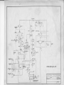
After the DTR-2000Lis hookedup to an AC power sourceand turned on, power is appliedto the
power transformer.This appliespowerto the Amperitetube which keepsthe unit from beingkeyedfor 3
minutes. Also, power is suppliedto the B+ and 12 volt sectionsof the unit. The B+ sectionis a standard
voltagedoubler,the only differencebeingthat the transformer
hasa tap for SSBwhich is highestvoltageand
from relayK2. RelayK2 alsoselectsthe approCWwhich is about 30% less. Thesetwo voltages
areselected
priatezenerdiodefor SSBor CWoperation.
Platecurrent is measured
acrossB- to groundthroughR18,voltageis measured
through R6, R7, R8,
and R9 to ground. SSBis about27OOVDC andCWis about1800VDC.
After the readylamp is lit, control of the unit is accomplished
throughthe standbyswitchon the front
panel. A path to groundis requiredfor keyingthe amplifier.
Signalis appliedto J2 and passes
to J1 throughK1, if the unit is in standby.lf the unit is out of standby,
signalgoesfrom J2 through FL-l (matchingdwice) to.t5 on the tube box. Now, the signalgoesthrough
two .01 discceramiccapacitors(CG& C7) to cathodeof the 8877tube. Cathodebiasis controlledby R1 in
whetheryou're operatingSSBor CW. CW is 24 volt zener,SSBis 8.9 volt
standby,or D2 or D3 depending
zener.This is donethroughKl and K2 relays.
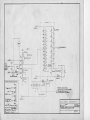
The gridsof the 8877 tube are groundeddirectlythroughclipsmountedinsidethe tube box. Outputof
the 8877 tube passes
througha parasiticchoketo C15. B+ is appliedto tubethrougha two stageplatechoke
circuit (RFC2,RFC3,C13, and C14). Amplifiedsignalgoesto a highlyefficientpi-networktank circuit
consistingof Cl8, L1, L2, and C21. Thereis only addedcapacitance
on the tune and loadcontrolsfor 160
meteroperation.
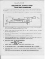
ALC is obtainedfrom the cathodeof the 8877tubethroughC8 andC9. The polarityof the ALC circuit
is set by Dl. As shownin the schematic,
ALC is negativegoingin the DTR-2000L. lf positiveALC is required,reverse
diodeD1.